instruction book - hobbicomanuals.hobbico.com/gpm/gpma0435-manual.pdf · read through this...
TRANSCRIPT

INSTRUCTION BOOK
WARRANTY
Great Planes Model Manufacturing Co , Inc guarantees this kit to be free of defects in both materialand workmanship at the date of purchase This warranty does not cover any component parts damagedby use or modification In no case shall Great Planes' liability exceed the original cost of the purchasedkit Further, Great Planes reserves the right to change or modify this warranty without notice
In that Great Planes has no control over the final assembly or material used for final assembly, noliability shall be assumed nor accepted for any damage resulting from the use by the user of the final user-assembled product By the act of using the user-assembled product the user accepts all resulting liability
If the buyer is not prepared to accept the liability associated with the use of this product, he isadvised to immediately return this kit in new and unused condition to the place of purchase.
READ THROUGH THIS INSTRUCTION BOOK FIRST.IT CONTAINS IMPORTANT INSTRUCTIONS ANDWARNINGS CONCERNING THE ASSEMBLY ANDUSE OF THIS MODEL.
P 0 BOX 788 URBANA ILL NOIS 61801 (217) 398-8970
Entire Contents ©1992 Hobbico, Inc F146P03 V1 1
TABLE OF CONTENTS
INTRODUCTION ........................3Precautions...................................3Other Items Required..................4Supplies and Tools Needed..........4Decisions You Must Make Now ..5Common Abbreviations ...............5Types of Wood .............................5Die Patterns..................................6Get Ready to Build.......................7
TAIL FEATHERS ........................7Build the Fins and Rudders..........7Build the Stabs and Elevators ......8Temporarily Install Hinges ..........9
WING.............................................10Spars.............................................10Build the Wing Panels..................10Assemble the Two Panels ............12Install the Wing Sheeting.............14Install the Aileron Torque Rods... 18
FUSELAGE ASSEMBLY............19Prepare the Sides..........................19Prepare the Firewall .....................21Assemble Fuselage.......................21Landing Gear (Fixed)...................23Landing Gear (Retracts)...............25General Fuselage Assembly.........27Install the Nose Gear Retract .......28Install Radio .................................29Retract Pushrods ..........................30Pushrods.......................................31Drill Engine Mount......................34Install Fuel Tank...........................35Final Fuselage Construction.........35Fit the Wing to the Fuselage ........37Build the Wing Turtle Deck.........39Engine Compartment ...................40
FINAL ASSEMBLY .......................42Install Wing Tips ...........................43Install Ailerons ..............................43Install Aileron Servo......................44Install Exhaust Nozzles .................45Cut Main Gear Retract Openings ..46
FINISHING....................................47Blend Wing to Fuse .......................47Instrument Console & Seats ..........47Prepare Canopy..............................47Balance the Airplane Laterally ......48Final Sanding.................................48Covering ........................................48Glue Fins and Stabs in Place .........49Glue Aileron Hinges......................49Glue Elev. and Rudder Hinges ......49Install Cockpit................................50Decals and Trim.............................50Wing Seating .................................51Re-install Engine and Radio..........51Balance Your Model ......................51Final Hookups and Checks............53
PRE-FLIGHT.................................53Charge the Batteries.......................53Find a Safe Place to Fly.................53Ground Check the Model ..............53Range Check Your Radio ..............53Engine Safety Precautions.............53AMA Safety Code.........................54
FLYING..........................................54Takeoff...........................................54Flying............................................54Important Caution..........................55Landing..........................................55Control Surface Throws.................55
2-VIEW............................................56

WARNING! THIS IS NOT A TOY!THIS IS NOT A BEGINNERS AIRPLANE!
This R/C kit and the model you will build is not a toy! It is capable of serious bodily harm andproperty damage IT IS YOUR RESPONSIBILITY AND YOURS ALONE — to build this kitcorrectly, properly install all R/C components and flying gear (engine, tank, pushrods, etc ) and totest the model and fly it only with experienced, competent help, using common sense and inaccordance with all safety standards as set down in the Academy of Model Aeronautics Safety CodeIt is suggested that you join the AMA and become properly insured before you attempt to fly thismodel IF YOU ARE JUST STARTING R/C MODELING, CONSULT YOUR LOCAL HOBBYSHOP OR WRITE TO THE ACADEMY OF MODEL AERONAUTICS TO FIND ANEXPERIENCED INSTRUCTOR IN YOUR AREA
Academy of Model Aeronautics5151 East Memorial Drive
Muncie, IN 47302-9252 (800) 435-9262
INTRODUCTIONCongratulations and thank you for purchasing the
Great Planes F-14 TOMCAT'
The Great Planes F-14 is a high performancepropeller-driven sport airplane that resembles the realF-14 Tomcat In the air, the prop is invisible, adding tothe realism The smoothness and speed of this airplaneallow you to experience the thrills of flying a jet-likeairplane without the complexity and high cost of a dueledfan model
Please inspect all parts carefully beforestarting to build! If any parts are missing,broken or defective, or if you have anyquestions about bui lding or f ly ing thisairplane, please call us at (217) 398-8970 andwe'll be glad to help. If you are calling forreplacement parts, please look up the partnumbers and the kit identification number(stamped on the end of the carton) and havethem ready when calling.
This is not a beginner's airplane! While the F-14TOMCAT is not d i f f i c u l t to build and flies great, wemust discourage you from selecting this kit as your firstR/C airplane It is very fast, highly maneuverable andlacks the self-recovery characteristics of a good basictrainer such as the Great Planes PT Series airplanesOn the other hand, if you are confident with your flyingskill and can safely handle aileron airplanes such as theGreat Planes Ultra-Sport Series or Big Stik Seriesairplanes, the F-14 is an excellent choice. If youcurrently fly an aileron airplane but you are unsure aboutyour ability to handle the F-14. we recommend that youbuild and fly a low-wing sport plane before building andflying your F-14
PRECAUTIONS
1. You must build the plane according to the plansand instructions. Do not alter or modify the model asdoing so may result in an unsafe or unflyable model Ina few cases the plans and instructions may differ slightlyfrom the photos In those instances you should assumethe plans and written instructions are correct Also youmay notice a slight difference in length between longerparts and the plans This is normal and is caused by theplans e x p a n d i n g and s h r i n k i n g w i t h the c h a n g i n gmoisture content in the an Do not modify the paits to fitthe plan
2 You must take time to build straight, true andstrong IMPORTANT - G lue s h o u l d never besubstituted tor a good joint Take a little extra time to geta close f i t t i ng j o i n t and glue i t proper ly It w i l l bestronger, neater, and much lighter than a bad joint heldtogether with a glob of glue!
3

3. You must use a proper R/C radio that is in first classcondit ion and meets the cur ren t AMA and FCCrequirements and the requirements of your local flyingclub, the correct sized engine and correct components(fuel tank, wheels, etc )
4. You must properly install all R/C and othercomponents so that the model operates properly on theground and in the air
5. You must test the operation of the model before thefirst and each successive flight to insure that all equipmentis operating Also you must make certain that the modelhas remained structurally sound
6. You must fly the model only with the competenthelp of a well experienced R/C pilot if you are not alreadyan experienced and knowledgeable R/C pilot.
Note We, as the kit manufacturer, can provide you with atop quality kit and great instructions, but ultimately thequality and flyability of your finished model depends onhow you bui ld it, therefore, we cannot in any wayguarantee the performance of your completed model, andno representations are expressed or implied as to theperformance or safety of your completed model
Remember: Take your time and followdirections to end up with a well-built model thatis straight and true.
OTHER ITEMS REQUIRED
D Four-channel radio with 4 or 5 servos (additional channeland retract servo required if retracts are being used)
D Propellers (see engine instructions for recommendedsizes) Top Flite® "Power Props" recommended.
D 2-1/4" Spinner (Hobbico 2-1/4" Jet spinner #HCAQ3750recommended)
D Fuel Tank (GPMQ4104)D 5/32" Wheel Collars (GPMQ4306)D Iron-on Covering Material (Top Flite Super MonoKote®
gray, black and cub yellow recommended)D Fuelproof Paint for Tail Cones, and possibly for trim
Note Chevron "Perfect Paint" matches Top Flite SuperMonoKote, and is available in spray cans.
D 36" Throttle Pushrod (GPMQ3710)D Silicone Fuel Tubing (GPMQ4131)D 1/16" thick Wing Seating Tape (GPMQ4422) or silicone
sealer see instructionsD Latex Foam Rubber Padding (HCAQ 1000)D 2 Plastic Pilots Williams Bros Military 1-1/2" Scale #171D Wheels (see page 5)
THE OPTIONAL RETRACTS ALSO REQUIRE:D Hobbico Low-Profile Retracts (HCAP4000)D #2 X 3/8" Socket Head Screws (GPMQ3120)D Dubro #103 Strip Aileron Horn (DUBQ1780)D Nose Gear Retract Pushrod (A Sullivan red outer
guide tube and a 34" threaded rod works well for this)D Three 3/32" Wheel Collars (GPMQ4302)D Screw-Lock Pushrod Connector (GPMQ3870)D 2-56 Metal Clevises (GPMQ3790)
SUPPLIES AND TOOLS NEEDED
D 2 oz Thin CA Adhesive (GPMR6003)D 2 oz Medium or Thick CA Adhesive (GPMR6009)D 2 5 oz Epoxy (GPMR6047)D Silicone AdhesiveD 7/64 Ball Driver (GPMR8003)D 440Tap(GPMR8101)D Hand or Electric DrillD Drill Bits 1/16", 5/64", 7/64", 1/8", 5/32", 3/16",
13/64", 1/4" and 5/16"D Sealing Iron and Heat Gun (Hobbico or Top Flite
recommended)D Hobby Saw (X-acto Razor Saw)D X-acto Knife, #11 BladesD PliersD Screw DriversD T-Pins (HCAR5200)D StraightedgeD Masking Tape (Required for construction)D Sandpaper (coarse, medium, fine grit)*D T-Bar Sanding Block (or similar)D Waxed PaperD Lightweight Balsa FillerD Vaseline Petroleum JellyD Isopropyi Rubbing Alcohol (70%)D 3M "77" Spray Adhesive (optional)D Dremel Moto Tool or similar (optional)D 5/64 and 2mm Ball Driver (for Hobbico Retracts)*NOTE: On our workbench, we have four 11" T-Barsanders, equipped with #50, #80, #100 and #150-gritsandpaper. This setup is all that is required foralmost any sanding task. We also keep some #320-grit wet-or-dry sandpaper handy for finish sandingbefore covering.4

DECISIONS YOU MUST MAKE NOWENGINE, MOUNT AND MUFFLERSELECTION
The recommended engine for the F 14 is a 60* - 75cubic inch displacement 2-cycle *NOTE: Performancemay be marginal if a non-Schneurle-ported 60 cu in2-Cycle engine is used. The engine you select willdetermine how you build the fuselage, so it is importantthat you have the engine close at hand while buildingBecause of the size limitations and the nature of thismodel, 4-cycle engines are more difficult to install andbalance and therefore are not recommended.
This kit includes a Great Planes MM60 engine mount(or s imilar mount) that fits most 60 - 61 (2-Cycle)engines (slight modification of this mount is required tomount the OS 61 SF by filing the inside edges of theengine mount beams) If the supplied mount can't bemodified to f i t your engine, it may be necessary topurchase a different mount (check with your hobbydealer).
SELECTION OF WHEELS
To save weight, we recommend using lightweightwheels REMEMBER: Large wheels are ugly andunrealistic on a model of this type, so try to keep thewheels as small as possible.
If you will be flying from a concrete or asphalt runway, werecommend 2-1/4" main wheels and a 2" nose wheel
For grass fields, larger wheels will be required, such as 2-1/2"main wheels and a 2-1/4" to 2-1/2" nose wheel.
If you will be installing retracts, you should try to limit thewheel size to a maximum of 2-1/4" main wheels and a 2" nosewheel or the wheel wells will be excessively large.
POSSIBLE RADIO INSTALLATIONSThe F-14 is designed to satisfy a wide variety of
modelers' desires The fol lowing radio i n s t a l l a t i o noptions will allow you to customize the plane to fitwhichever radio you want to use.
Our recommended radio ins ta l la t ion requires 5standard servos and a 180 degree retract servo (if retractsare used) This will allow you to use one standard servofor the rudders, two servos for the elevators (one foreach), one for the throttle and one for the ailerons Thisset-up will give you very precise control and is easy toinstall
You can also fly the plane with 4 standard servos byusing only one servo to drive both elevators In this casethe elevator servo is mounted up in a front servo tray andtwo long pushrods are used This will work Ok, but thereis generally more "play" in the elevators (due to thelonger, curved pushrods) This method is notrecommended if you intend to use a high powered engineor do a lot of high speed flying
Both rudders can be operated from one servo withoutany problems because their linkage is much straighter Ifyou don't plan on doing much acrobatic flying, you caneven get by with only one operating rudder In this caseyou would just run one pushrod straight back to therudder on the same side as the servo The other rudderwould be glued on to the fin and would not move
RETRACTABLE LANDING GEAR (optional)This airplane flies very well with a fixed landing gear,
and retracts are not necessary, however, they do addrealism and speed, and are a nice addition (it you areprepared for the extra work involved in their installation)Since the retracts are all located in the fuselage, oneretract servo (such as the Futaba FP-S136G) can be usedto actuate all three retracts
COMMON ABBREVIATIONS USED INTHIS BOOK AND ON THE PLANS:
Elev = ElevatorFuse = FuselageLE = Leading Edge (front)LG = Landing GearPly = PlywoodStab = StabilizerTE = Trailing Edge (rear)
= Inches
TYPES OF WOOD
Balsa Basswood Plywood
6

GET READY TO BUILD
D 1. Unroll the plan sheets and re-roll them insideout. This will help them lie flat.
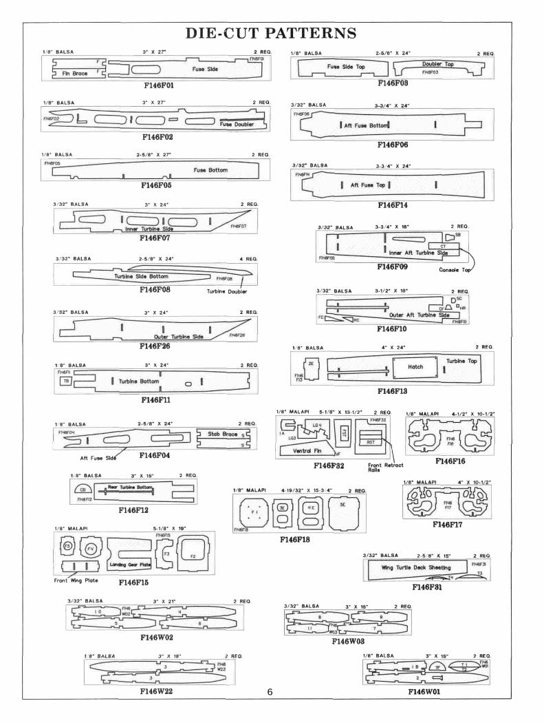
D 2. Remove all parts from the box. As you do,determine the name of each part by comparing it with theplans and the parts list at the back of this book. Using afelt tip pen, write the part name or size on each piece toavoid confusion later. Use the die-cut part patternsshown on page 6 to identify the die-cut parts, but do notpunch them out until you are ready to use them. Saveall scraps. If any of the die-cut parts are diff icul t topunch out, do not force them! Instead, first cut aroundthe parts with an X-acto knife. After punching out thedie-cut parts, use your T-Bar or sanding block to lightlysand the edges to remove any die-cutting irregularities.
D 3. As you identify and mark the parts, separatethem into groups, such as fuse (fuselage), wing, fin andstab (stabilizer), and hardware.
"TAIL FEATHERS"
D D 3. Cut the tip of the fin rear to match the leadingedge sweep of the fin front. Glue the little triangle pieceof scrap into the "V" at the bottom. Cut the 1/4" x 5/8"x 9" balsa stick (F146R04) in half to make two 4-1/2"long fin tips. Glue the tip in place at the end of the finrear.
BUILD THE FINS AND RUDDERS
D 1. Tape the fuselage side view portion of the plandown onto your flat work surface. Tape a piece of waxedpaper over the fin and rudder portion of the plan.
D D 4. Draw a l ine parallel w i t h the t ra i l ing edge ofthe fin and 1/4" in front of it. Draw another line parallelwith the bottom edge of the fin and 1" above it. Cut outa clearance notch for the torque rods using the lines as aguide as shown in the photo.
D D 2. Glue the 1/4" balsa fin from ( 1 4 6 R 0 1 ) tothe 1/4" balsa fin rear (F146R03) so their bottoms areeven with each other. Note that there will be a triangle ofwood missing between the two pieces. This can be filledin the next step.
D D 5. Use a sanding block with medium (150) gritsandpaper to sand the edges and both sides of the stabsmooth. Carefully draw a centerline al l around theedges of the stab and elevator. This will make it easier tomaintain symmetry when sanding later.
7
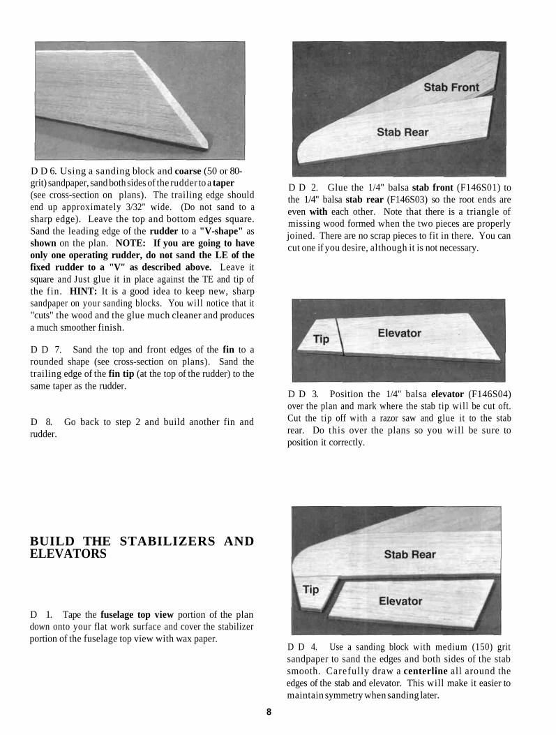
D D 6. Using a sanding block and coarse (50 or 80-grit) sandpaper, sand both sides of the rudder to a taper(see cross-section on plans). The trailing edge shouldend up approximately 3/32" wide. (Do not sand to asharp edge). Leave the top and bottom edges square.Sand the leading edge of the rudder to a "V-shape" asshown on the plan. NOTE: If you are going to haveonly one operating rudder, do not sand the LE of thefixed rudder to a "V" as described above. Leave itsquare and Just glue it in place against the TE and tip ofthe fin. HINT: It is a good idea to keep new, sharpsandpaper on your sanding blocks. You will notice that it"cuts" the wood and the glue much cleaner and producesa much smoother finish.
D D 7. Sand the top and front edges of the fin to arounded shape (see cross-section on plans). Sand thetrailing edge of the fin tip (at the top of the rudder) to thesame taper as the rudder.
D 8. Go back to step 2 and build another fin andrudder.
D D 2. Glue the 1/4" balsa stab front (F146S01) tothe 1/4" balsa stab rear (F146S03) so the root ends areeven with each other. Note that there is a triangle ofmissing wood formed when the two pieces are properlyjoined. There are no scrap pieces to fit in there. You cancut one if you desire, although it is not necessary.
D D 3. Position the 1/4" balsa elevator (F146S04)over the plan and mark where the stab tip will be cut oft.Cut the tip off with a razor saw and glue it to the stabrear. Do this over the plans so you will be sure toposition it correctly.
BUILD THE STABILIZERS ANDELEVATORS
D 1. Tape the fuselage top view portion of the plandown onto your flat work surface and cover the stabilizerportion of the fuselage top view with wax paper.
D D 4. Use a sanding block with medium (150) gritsandpaper to sand the edges and both sides of the stabsmooth. Carefully draw a centerline all around theedges of the stab and elevator. This will make it easier tomaintain symmetry when sanding later.
8

D D 5. Using a sanding block and coarse (50 or 80-grit) sandpaper, sand both sides of the elevator to a taper(see cross-section on plans). The trailing edge shouldend up approximately 3/32" wide. (Do not sand to asharp edge). Leave the ends square. Sand the leadingedge of the elevator to a "V-shape" as shown on theplan.
D D 6. Sand the tip and front edges of the stab to arounded shape (see cross-section on plans). Sand thetrai l ing edge of the stab tip to the same taper as theelevator.
D D 7. Draw a line parallel with the trailing edge ofthe stab and 1/4" in front of it . Draw another l ineparallel with the root edge of the stab and 1" out from it.Cut out a clearance notch for the torque rods just as youdid on the fins earlier.
D 8. Go back to step 2 and build another stab andelevator.
B. Make three or four more cuts in the same line, goingslightly deeper each time. As you make theseadditional cuts. work on going straight into the wood.Continue this process while "wiggling" the knifehandle forward and backward un t i l the blade hasreached the proper depth for the hinge.
C. Trial fit the hinge into the slot. If the hinge isdifficult to push in. re-insert the knife and move itback and forth in the slot a few times to enlarge theslot. Do not glue the hinges yet.
TEMPORARILY INSTALL HINGESAND TORQUE RODS
D 1. Using the plans as a guide, mark the hingelocations on the stabs, elevators, fins and rudders. Alsodesignate one of each surface as being "right" and theothers as "left."
CAUTION!!! You must use extreme care whencutting hinge slots with an X-acto knife, toavoid cutting yourself! If the balsa part breakswhile you are pushing on the knife, the bladecould go into your hand before you know it! Agood precaution is to wear leather gloves whileperforming the following steps.
D 2. Cut the hinge slots on the centerlines you drewearlier. Our recommended hinge slotting method isdescribed below.
A. Begin by carefully cutting a very shallow slit at thehinge location. The first cut is to establish your cut inthe right place, so concentrate on staying on the lineand don't cut too deep.
D 3. Check the plans and mark the location of thetorque rods on the rudders and elevators. Dri l l 7/64"holes in the rudders and elevators (the holes are drilledslightly oversize to allow for positioning, and to create ahard epoxy "sleeve" around the wire). Groove the rudderand elevator LE to accept the torque rod wires and nylonbearings (See below).
HINT: Using an X-acto knife, sharpen the inside of oneend of a 1/8" diameter brass tube. and use it to cut thegroove in the leading edge of the rudders and elevators.
9

D 4. Determine the torque rod bearing locationsfrom the plan. Then use a hinge slotting tool to cut theslots in the stabs and f ins tor the nylon torque rodbearings. Cut a groove in the trailing edge of the stabsand fins to accept the torque rods and nylon bearings.
TWO WARPED SPARS INSTALLEDTHIS WAY WILL RESULT IN A
STRAIGHT WING
TWO WARPED SPARS INSTALLEDTHIS WAY WILL RESULT IN A
WARPED WING
D 5. Trial fit all these parts together using the torquerods and hinges and t r im the fin tips flush wi th thetrailing edges of the rudders. Check the operation of thecontrol surfaces but do not glue anything yet.
"WING"NOTE: The following instructions explain how to buildthe wing on a flat surface, directly on the plans. The jigtabs will automatically build in 1-3/4 degrees of washoutand enable you to build a wing as straight as your worksurface. Because this wing has a lot of taper and sweep,it is not advisable to build it on a Great Planes Wing Jig.
imperfections. If possible, position each spar so theimperfections (if any) are on the outer half of the wingpanel (toward the tip), where they will be least affectedby high stress. If the spars are warped slightly, try to"balance them out" by instal l ing the warped spars inopposite directions (see sketch). NOTICE: If you feelthat any of the wing parts are unusable due to severewarps or other defects, give us a call and we'll replacethe parts.
D 2. Sand 2" of one end of each 1/8" x 3/8" x 18"balsa spar doubler (F146W05) to a taper as shown inthe "Wing Spar Detail" on the plan.
D 3. Glue the spar doublers to the 1/8" x 3/8" x 30"balsa spars (F146F04) with thick CA as shown in the"Wing Spar Detail." Take your time and press the sparassembly flat against the work surface while the glue iscuring. Also rotate the assembly onto its side and pressit down to keep the doubler and spar aligned and straight.Do this on a flat work surface and most warps can beeliminated. Wipe off any excess glue before it cures.
SPARS
D 1. Before using the hard balsa spars, examinethem carefully for possible imperfections. Look forknots, soft spots, diagonal gram and any other
BUILD THE WING PANELS
NOTE: If you build in the conventional manner, bypinning the components to your workbench, it wil l behelpful to build the wing on a piece of "Celotex"* or
10

other semi-soft (and flat) surface, into which you mayeasily stick pins to f i rmly hold down the wing partswhile building, to avoid warps. *Available from lumbercompanies and home centers.
NOTE: You should also be aware of the following:This wing is constructed with 1-3/4 degrees of washout(TE higher than LE at the wing tip) buil t- in. When thewing is upright, the tabs on the rear portion of the ribs setthe ribs at the proper angles to achieve this slight twist.When you flip the wing over to work on the bottom side,the jig tabs on the top of the wing will hold the correctwashout in the wing.
D D 1. Cut the Wing Plan apart on the heavy dashedline. Tape the right (or left) wing panel plan to your flatwork surface, and cover the wing drawing with waxedpaper (so you won't glue the wing to the plan!).
D D 2. Carefully punch out all the die-cut 3/32" and1/8" balsa wing ribs. Sand the edges slightly to removeany die-cutting irregularities or "fuzz."
with the rear-most jig tab against the work surface.Use a 90-degree triangle to keep the ribs vertical.
D D 5. The shaped and notched wing trailing edges(F146W07) are fastened together by a thin strip of balsa.Separate them by cutting with an X-acto knife. Positionthe TE in place by working the rear ends of the ribs intothe notches in the TE. Center the TE vertically on eachrib and glue it in place with thin CA.
D D 3. Cross-pin one of the spars to the plan with thelong spar down. and with the thick end (2 laminations)toward the root. The tapered end of the spar doublershould end just inside (1/4") of rib W8.
D D 6. Glue the top spar in place (with the long sparon top). Make sure it is fully seated in the notches so itdoes not s t i ck above the top su r f ace of the ribs.Remember, the spar doubler stops just inside rib W8.
D D 4. Glue ribs W2 through W11 onto the spar intheir correct position. Notice that the ribs are installed
D D 7. Position a shaped balsa Leading Edge(F146W06) over the Leading Edge Template on the wingplan and mark where the notch goes. Use a razor saw to
11
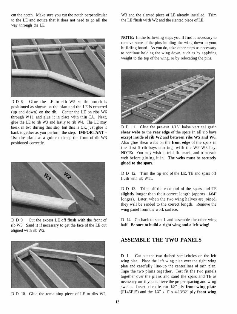
cut the notch. Make sure you cut the notch perpendicularto the LE and notice that it does not need to go all theway through the LE.
W3 and the slanted piece of LE already installed. Trimthe LE flush with W2 and the slanted piece of LE.
D D 8. G lue the LE to r i b W5 so the notch ispositioned as shown on the plan and the LE is centered(up and down) on the rib. Center the LE on ribs W6through W11 and glue it in place with thin CA. Next,glue the LE to rib W3 and lastly to rib W4. The LE maybreak in two during this step, but this is OK, just glue itback together as you perform the step. IMPORTANT -Use the plans as a guide to keep the front of rib W3positioned correctly.
D D 9. Cut the excess LE off flush with the front ofrib W3. Sand it if necessary to get the face of the LE cutaligned with rib W2.
D D 10. Glue the remaining piece of LE to ribs W2,
NOTE: In the following steps you'll find it necessary toremove some of the pins holding the wing down to yourbuilding board. As you do, take other steps as necessaryto continue holding the wing down, such as by applyingweight to the top of the wing, or by relocating the pins.
D D 11 . Glue the pre-cut 1/16" balsa vertical grainshear webs to the rear edge of the spars in all rib baysexcept inside of rib W2 and between ribs W5 and W6.Also glue shear webs on the front edge of the spars inthe first 5 rib bays starting with the W2-W3 bay.NOTE: You may wish to trial fit, mark, and trim eachweb before gluing it in. The webs must be securelyglued to the spars.
D D 12. Trim the tip end of the LE, TE and spars offflush with rib W11.
D D 13. Trim off the root end of the spars and TEslightly longer than their correct length (approx. 1/64"longer). Later, when the two wing halves are joined,they will be sanded to the correct length. Remove thewing panel from the work surface.
D 14. Go back to step 1 and assemble the other winghalf. Be sure to build a right wing and a left wing!
ASSEMBLE THE TWO PANELS
D 1. Cut out the two dashed semi-circles on the leftwing plan. Place the left wing plan over the right wingplan and carefully line-up the centerlines of each plan.Tape the two plans together. Test fit the two panelstogether over the plans and sand the spars and TE asnecessary until you achieve the proper spacing and wingsweep. Insert the die-cut 1/8" ply front wing plate(F146F15) and the 1/4" x 1" x 4-13/32" ply front wing
12
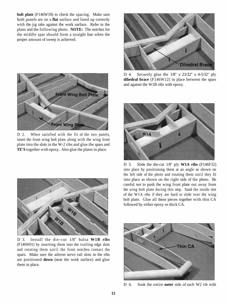
bolt plate (F146W18) to check the spacing. Make sureboth panels are on a flat surface and lined up correctlywith the jig tabs against the work surface. Refer to theplans and the following photo. NOTE: The notches forthe middle spar should form a straight line when theproper amount of sweep is achieved.
D 2. When satisfied with the fit of the two panels,insert the front wing bolt plate along with the wing frontplate into the slots in the W-2 ribs and glue the spars andTE'S together with epoxy. Also glue the plates in place.
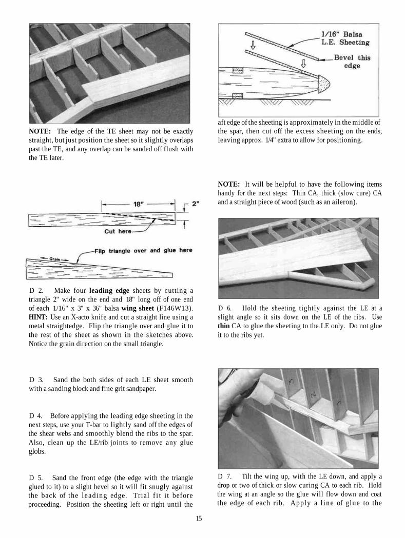
D 4. Securely glue the 1/8" x 23/32" x 4-5/32" plydihedral brace (F146W12) in place between the sparsand against the W1B ribs with epoxy.
D 3. Install the d ie-cut 1/8" balsa W1B ribs(F146W01) by inserting them into the trailing edge slotsand rotating them u n t i l the front notches contact thespars. Make sure the aileron servo rail slots in the ribsare positioned down (near the work surface) and gluethem in place.
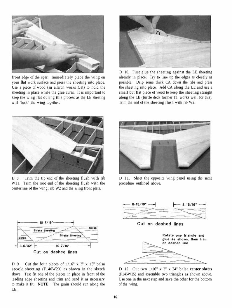
D 5. Slide the die-cut 1/8" ply W1A ribs (F146F32)into place by positioning them at an angle as shown onthe left side of the photo and rotating them unti l they fitinto place as shown on the right side of the photo. Becareful not to push the wing front plate out away fromthe wing bolt plate during this step. Sand the inside slotof the W1A ribs if they are hard to slide over the wingbolt plate. Glue all these pieces together with thin CAfollowed by either epoxy or thick CA.
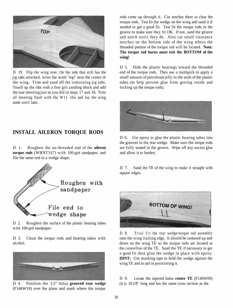
D 6. Soak the entire outer side of each W2 rib with
13

thin CA to help harden the wood. Cut four 1" longpieces of 1/2" triangle from the 1/2" x 36" triangle(WSTR001H) and glue them in place above and belowthe front wing bolt plate and against the W2 ribs. Addepoxy or thick CA around every joint in this area tomake sure everything is securely glued in place.
D 7. Trim the 1/8" x 3/8" x 24" balsa top middlespar (F146W17) to fit in place by positioning it in thenotches and using a razor saw to accurately cut the taperon both ends. NOTE: It is important to get the bestjoint possible between the middle spars and the mainspars. Securely glue the middle spar in place with epoxy.
of the middle spar in all rib bays. The shear webs will betoo tall and too wide, so just trim them to fit and securelyglue them in place.
D 8. Flip the wing over and install the 1/8" x 3/8" x24" balsa bottom middle spar just as you did the topone in the last step. Make a nice epoxy fillet where bothmiddle spars contact the main spars.
D 10. Cut pieces of shear webs to l i t in the three centerbays of the main spar and securely glue them in place.
D 11. Cut two 1-1/2" long aileron servo rails fromthe 1/8" x 3/8" x 15" basswood strip (F146F30). Slidethese into the slots in the W1 ribs and use your aileronservo to properly space them. They should be installedas far forward as possible and far enough apart to allowyou to get the servo in and out. Securely glue them inplace.
INSTALL THE WING SHEETING
NOTE: In the next steps, maintain straightness bykeeping the jig tabs and spar down on the flatsurface.
D 9. Turn the wing back over so the top is up andinstall 1/16" balsa shear webs on the front and the back
D 1. Lightly sand the tops of the ribs to blend withthe notched trailing edge, then glue the two top 1/16" x1" x 30" balsa trailing edge sheets (F146W14) in place.
14
NOTE: The edge of the TE sheet may not be exactlystraight, but just position the sheet so it slightly overlapspast the TE, and any overlap can be sanded off flush withthe TE later.
aft edge of the sheeting is approximately in the middle ofthe spar, then cut off the excess sheeting on the ends,leaving approx. 1/4" extra to allow for positioning.
D 2. Make four leading edge sheets by cutting atriangle 2" wide on the end and 18" long off of one endof each 1/16" x 3" x 36" balsa wing sheet (F146W13).HINT: Use an X-acto knife and cut a straight line using ametal straightedge. Flip the triangle over and glue it tothe rest of the sheet as shown in the sketches above.Notice the grain direction on the small triangle.
NOTE: It will be helpful to have the following itemshandy for the next steps: Thin CA, thick (slow cure) CAand a straight piece of wood (such as an aileron).
D 6. Hold the sheeting t ight ly against the LE at aslight angle so it sits down on the LE of the ribs. Usethin CA to glue the sheeting to the LE only. Do not glueit to the ribs yet.
D 3. Sand the both sides of each LE sheet smoothwith a sanding block and fine grit sandpaper.
D 4. Before applying the leading edge sheeting in thenext steps, use your T-bar to lightly sand off the edges ofthe shear webs and smoothly blend the ribs to the spar.Also, clean up the LE/rib joints to remove any glueglobs.
D 5. Sand the front edge (the edge with the triangleglued to it) to a slight bevel so it will fit snugly againstthe back of the leading edge. Trial f i t i t beforeproceeding. Position the sheeting left or right until the
D 7. Tilt the wing up, with the LE down, and apply adrop or two of thick or slow curing CA to each rib. Holdthe wing at an angle so the glue wil l flow down and coatthe edge of each rib. Apply a l ine of glue to the
15
front edge of the spar. Immediately place the wing onyour flat work surface and press the sheeting into place.Use a piece of wood (an aileron works OK) to hold thesheeting in place while the glue cures. It is important tokeep the wing flat during this process as the LE sheetingwill "lock" the wing together.
D 10. First glue the sheeting against the LE sheetingalready in place. Try to line up the edges as closely aspossible. Drip some thick CA down the ribs and pressthe sheeting into place. Add CA along the LE and use asmall but flat piece of wood to keep the sheeting straightalong the LE (turtle deck former T1 works well for this).Trim the end of the sheeting flush with rib W2.
D 8. Trim the tip end of the sheeting flush with ribW11. Trim the root end of the sheeting flush with thecenterline of the wing, rib W2 and the wing front plate.
D 11. Sheet the opposite wing panel using the sameprocedure outlined above.
D 9. Cut the four pieces of 1/16" x 3" x 15" balsastock sheeting (F146W23) as shown in the sketchabove. Test fit one of the pieces in place in front of theleading edge sheeting and trim and sand it as necessaryto make it fit. NOTE: The grain should run along theLE.
D 12. Cut two 1/16" x 3" x 24" balsa center sheets(F146W15) and assemble two triangles as shown above.Use one in the next step and save the other for the bottomof the wing.
16

D 13. Test fit the triangle sheeting into place and sandit if necessary to achieve a good fit. It should go halfway back on the middle spar. Glue it in place byapplying thick or slow curing CA to the ribs and sparsand holding the sheeting in place while the glue cures.
D 16. I n s t a l l the r e m a i n i n g 1/16" lead ing edgesheeting, the strake sheeting and the center triangle sheetusing the same procedure outlined in steps 2 - 1 3 .
D 14. Flip the wing over and carefully trim off the jigtabs on the bottom of the wing (the side opposite the sideyou just sheeted). Use a sanding block with a fine gritsandpaper to touch up where the tabs were and to blendthe ribs into the TE. Be careful not to change theshape of the ribs during this step.
D 17. Trim one of the 1/16" x 3" x 18" balsa rearwing sheeting (F146W21) pieces to fit in place behindthe triangle center sheet. An easy way to do this is totape it in place behind the triangle center sheet and lay astraight edge along the front edge of the 1" TE sheeting.Mark where both sides of the TE sheeting continue underthe rear sheeting. Remove the rear sheeting and cut outthe triangle formed by the lines you marked. Cut anotherof the rear sheeting pieces in half lengthwise and glueone half to the rear edge of the piece you just trimmed tofit.
Tape the sheeting back into place and mark where the TEsheeting intersects the outside edges. Cut the aft piece ofsheeting to fit and glue the rear sheeting in place withthick or slow CA.
D 15. Add the remaining two 1/16" x 1" x 30" balsaTE sheets just as you did earlier on the top surface. Doone panel at a time and keep the panel flat on the worksurface unti l the glue cures. Note: Due to the taper ofthe wing, the jig tabs on the top surface of the wing willonly keep one panel flat at a time.
D 18. Cut a semicircle out of the sheeting between ribsW4 and W5 as shown in the next photo.
17
D 19. Flip the wing over. On the side that still has thejig tabs attached, write the word "top" near the center ofthe wing. Trim and sand off the remaining jig tabs.Touch up the ribs with a fine grit sanding block and addthe rear sheeting just as you did in steps 17 and 18. Trimall sheeting flush with the W11 ribs and lay the wingaside until later.
INSTALL AILERON TORQUE RODS
rods come up through it. Cut notches there to clear thetorque rods. Test fit the wedge on the wing and sand it ifneeded to get a good fit. Test fit the torque rods in thegroove to make sure they fit OK. If not, sand the grooveand notch u n t i l they do. Also cut small clearancenotches on the bottom side of the wing where thethreaded portion of the torque rod will be located. Note:The torque rod horns must exit the BOTTOM of thewing!
D 5. Slide the plastic bearings toward the threadedend of the torque rods. Then use a toothpick to apply asmall amount of petroleum jelly to the ends of the plastictubes (to help prevent glue from getting inside andlocking up the torque rods).
D 1. Roughen the un-threaded end of the ailerontorque rods (WBNT167) with 100-grit sandpaper, andfile the same end to a wedge shape.
D 6. Use epoxy to glue the plastic bearing tubes intothe grooves in the rear wedge. Make sure the torque rodsare fully seated in the groove. Wipe off any excess glueand allow it to harden.
D 2. Roughen the surface of the plastic bearing tubeswith 100-grit sandpaper.
D 3. Clean the torque rods and bearing tubes withalcohol.
D 4. Position the 1/2" balsa grooved rear wedge(F146W10) over the plans and mark where the torque
D 7. Sand the TE of the wing to make it straight withsquare edges.
D 8. T r i a l f i t the rear wedge/torque rod assemblyonto the wing trailing edge. It should be centered up anddown on the wing TE so the torque rods are located atthe centerline of the TE. Sand the TE if necessary to geta good fit then glue the wedge in place wi th epoxy.HINT: Use masking tape to hold the wedge against thewing TE and to aid in positioning it.
D 9. Locate the tapered balsa center TE (F146W09)(it is 10-1/8" long and has the same cross section as the
18
ailerons) and cut a notch in both ends to clear the torquerods. Also sand the very front of the ends if needed tomake it fit in place against the rear wedge. Tape it inplace with masking tape and check to make sure it is nottilted up or down You can use the edge of a 1/8" balsafuse doubler (F146F02) as a template to check thecenter TE alignment, but be sure to check it from the topand the bottom of the wing When satisfied with itsal ignment, glue it in place wi th t h in CA Be verycareful around the ends so you don't glue the torquerods!
D 10 Use some lightweight wood f i l l e r to blend therear wedge and center TE in with the contour of thewing. After the filler has cured, use a sanding block tosmooth things out.
This is all we will do to the wing until after it hasbeen fitted to the fuselage and the turtle deck has beenadded This will help keep the wing tips, cap strips andailerons from getting dinged up in the process.
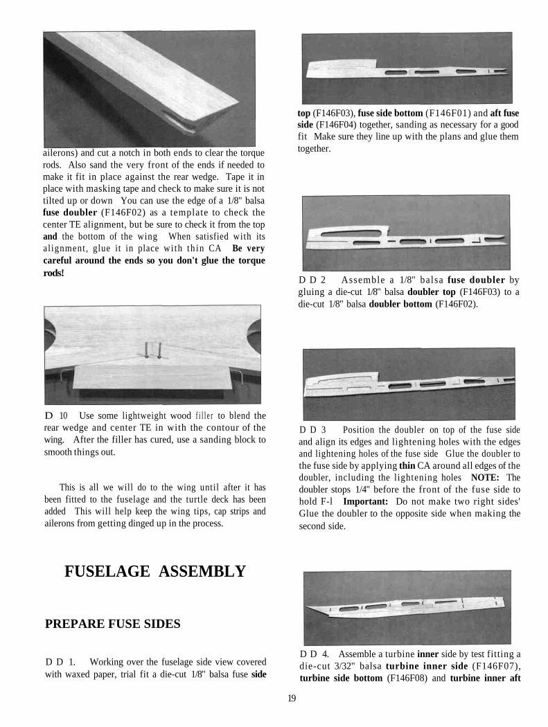
top (F146F03), fuse side bottom (F146F01) and aft fuseside (F146F04) together, sanding as necessary for a goodfit Make sure they line up with the plans and glue themtogether.
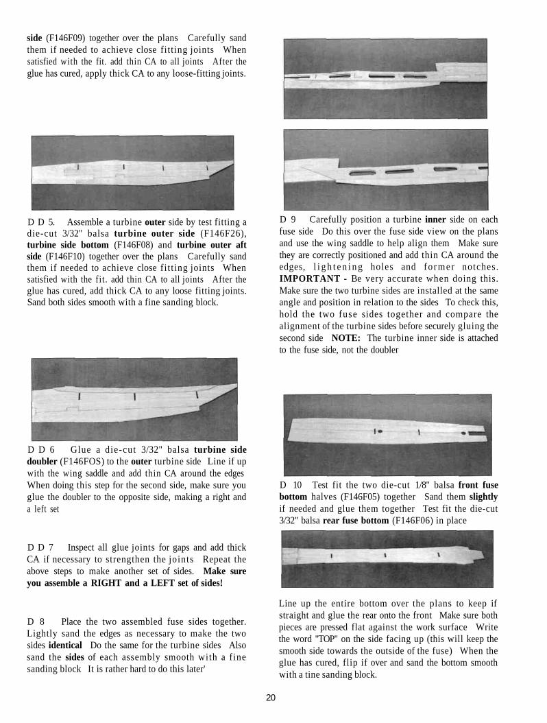
D D 2 Assemble a 1/8" balsa fuse doubler bygluing a die-cut 1/8" balsa doubler top (F146F03) to adie-cut 1/8" balsa doubler bottom (F146F02).
D D 3 Position the doubler on top of the fuse sideand align its edges and lightening holes with the edgesand lightening holes of the fuse side Glue the doubler tothe fuse side by applying thin CA around all edges of thedoubler, including the lightening holes NOTE: Thedoubler stops 1/4" before the front of the fuse side tohold F-l Important: Do not make two right sides'Glue the doubler to the opposite side when making thesecond side.
FUSELAGE ASSEMBLY
PREPARE FUSE SIDES
D D 1. Working over the fuselage side view coveredwith waxed paper, trial fit a die-cut 1/8" balsa fuse side
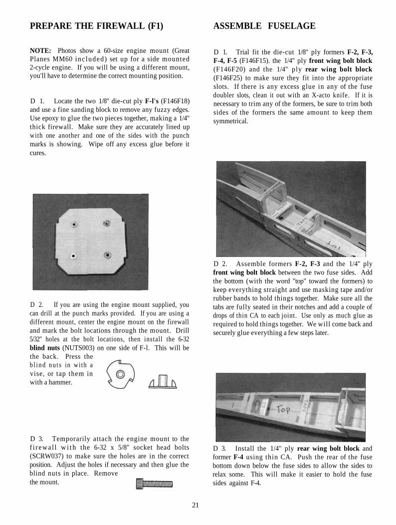
D D 4. Assemble a turbine inner side by test fitting adie-cut 3/32" balsa turbine inner side (F146F07),turbine side bottom (F146F08) and turbine inner aft
19
side (F146F09) together over the plans Carefully sandthem if needed to achieve close fitting joints Whensatisfied with the fit. add thin CA to all joints After theglue has cured, apply thick CA to any loose-fitting joints.
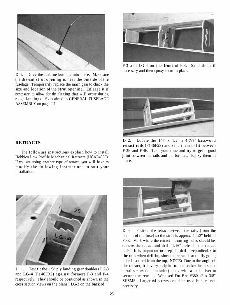
D D 5. Assemble a turbine outer side by test fitting adie-cut 3/32" balsa turbine outer side (F146F26),turbine side bottom (F146F08) and turbine outer aftside (F146F10) together over the plans Carefully sandthem if needed to achieve close fit t ing joints Whensatisfied with the fit . add thin CA to all joints After theglue has cured, add thick CA to any loose fitting joints.Sand both sides smooth with a fine sanding block.
D 9 Carefully position a turbine inner side on eachfuse side Do this over the fuse side view on the plansand use the wing saddle to help align them Make surethey are correctly positioned and add thin CA around theedges, l i g h t e n i n g holes and fo rmer notches.IMPORTANT - Be very accurate when doing this.Make sure the two turbine sides are installed at the sameangle and position in relation to the sides To check this,hold the two fuse sides together and compare thealignment of the turbine sides before securely gluing thesecond side NOTE: The turbine inner side is attachedto the fuse side, not the doubler
D D 6 Glue a die-cut 3/32" balsa turbine sidedoubler (F146FOS) to the outer turbine side Line if upwith the wing saddle and add thin CA around the edgesWhen doing this step for the second side, make sure youglue the doubler to the opposite side, making a right anda left set
D 10 Test fit the two die-cut 1/8" balsa front fusebottom halves (F146F05) together Sand them slightlyif needed and glue them together Test fit the die-cut3/32" balsa rear fuse bottom (F146F06) in place
D D 7 Inspect all glue joints for gaps and add thickCA if necessary to strengthen the joints Repeat theabove steps to make another set of sides. Make sureyou assemble a RIGHT and a LEFT set of sides!
D 8 Place the two assembled fuse sides together.Lightly sand the edges as necessary to make the twosides identical Do the same for the turbine sides Alsosand the sides of each assembly smooth with a finesanding block It is rather hard to do this later'
Line up the entire bottom over the plans to keep ifstraight and glue the rear onto the front Make sure bothpieces are pressed flat against the work surface Writethe word "TOP" on the side facing up (this will keep thesmooth side towards the outside of the fuse) When theglue has cured, flip if over and sand the bottom smoothwith a tine sanding block.
20
PREPARE THE FIREWALL (F1) ASSEMBLE FUSELAGE
NOTE: Photos show a 60-size engine mount (GreatPlanes MM60 inc luded) set up for a side mounted2-cycle engine. If you will be using a different mount,you'll have to determine the correct mounting position.
D 1. Locate the two 1/8" die-cut ply F-l's (F146F18)and use a fine sanding block to remove any fuzzy edges.Use epoxy to glue the two pieces together, making a 1/4"thick firewall. Make sure they are accurately lined upwith one another and one of the sides with the punchmarks is showing. Wipe off any excess glue before itcures.
D 1. Trial fit the die-cut 1/8" ply formers F-2, F-3,F-4, F-5 (F146F15). the 1/4" ply front wing bolt block(F146F20) and the 1/4" ply rear wing bolt block(F146F25) to make sure they fit into the appropriateslots. If there is any excess glue in any of the fusedoubler slots, clean it out with an X-acto knife. If it isnecessary to trim any of the formers, be sure to trim bothsides of the formers the same amount to keep themsymmetrical.
D 2. If you are using the engine mount supplied, youcan drill at the punch marks provided. If you are using adifferent mount, center the engine mount on the firewalland mark the bolt locations through the mount. Drill5/32" holes at the bolt locations, then install the 6-32blind nuts (NUTS003) on one side of F-l. This will bethe back. Press theb l i n d n u t s in wi th avise, or tap them inwith a hammer.
D 3. Temporarily attach the engine mount to thef i r ewa l l w i t h the 6-32 x 5/8" socket head bolts(SCRW037) to make sure the holes are in the correctposition. Adjust the holes if necessary and then glue theblind nuts in place. Removethe mount.
D 2. Assemble formers F-2, F-3 and the 1/4" plyfront wing bolt block between the two fuse sides. Addthe bottom (with the word "top" toward the formers) tokeep everything straight and use masking tape and/orrubber bands to hold things together. Make sure all thetabs are fully seated in their notches and add a couple ofdrops of thin CA to each joint. Use only as much glue asrequired to hold things together. We will come back andsecurely glue everything a few steps later.
D 3. Install the 1/4" ply rear wing bolt block andformer F-4 using thin CA. Push the rear of the fusebottom down below the fuse sides to allow the sides torelax some. This will make it easier to hold the fusesides against F-4.
21

D 4. Snap former F-5 into place and glue it to thefuse sides only. Keep the fuse bottom pushed down fornow.
D 5. Slide formers F-6 (F146F16) and F-7 (F146F17)into their respective slots and pull the fuse sides outagainst the formers. Push the fuse bottom up against thebottom of F-5, F-6 and F-7 to lock the fuse sides inplace. Glue the fuse sides and the fuse bottom to theformers below the fuse bottom but do not glue the sidesabove the bottom yet.
fuselage. Sand the tank floor if necessary to get a goodfit around the firewall and glue these in place with epoxy.Before the epoxy cures, pul l the fu se bottom up intoplace and center the fuse sides with the bottom. Glue thebottom into place with CA The triangular gaps formedare for 1/2" triangle stock which wil l be added later.NOTE: If you are not installing retracts and would liketo use a larger than 10oz. fuel tank, you can leave thefuel tank floor out. It does add some rigidity to the frontbut it is not absolutely necessaiy. Although the fuselagewill hold a much larger tank, the balance of the planemay be greatly affected by the extra fuel in the nose.
D 6. Sight along the rear portion of the fuse bottomto make sure it lays smoothly and then add thin CA alongthe fuse bottom from F-2 back to F-7.
D 8. Tack glue former F-2E (F146F13) into place onthe turbine inner side with one drop of thin CA. Tackglue a turbine outer side onto F-2E, F-6 and F-7 with thedoubler facing the fuselage. Install the opposite turbineside the same way. Do not securely glue around F-2Euntil the rest of the formers are installed.
D 7. Test fit the 1/8" ply fuel tank floor (F146F15)and the firewall (F-l) into place in the front of the
D 9. Snap formers F-3E. F-4E and F-5E (F146F18)into place on both sides of the fuselage. Do not glue
22

yet! Due to the bending of the turbine side. it is normalfor formers F-2E to slant slightly. This is all right but tryto make both slant the same amount.
FIXED GEAR
D 10. Locate the die-cut 1/8" balsa front turbinebottoms (F147F11) and rear turbine bottoms(F146F12) and assemble the turbine bottoms over theplans. Sand the pieces if needed to achieve a good jointand glue them together. Test fit the assembled turbinebottoms in place on the bottom of each turbine. Do notglue the bottoms in place! Use the bottoms as guides toalign the formers and glue the formers to the sides only.
D 1. Test fit the 1/8" ply landing gear doublers LG-3and LG-4 (F146F32) aga ins t formers F-3 and F-4respectively. They should be positioned as shown in the
D 1 1 . Posi t ion the d ie -cu t 1/8" balsa inlet braces(F146F11) so they hold the turb ine outer sides at anatural curve, as shown on the plans and glue them inplace. Remove the bottoms after the glue has cured.
D 12. Add 1/2" balsa triangle (WSTR001H) aboveand below both 1/4" ply wing bolt blocks and then soakthe fuse sides around both with thin CA to strengthenthis area.
SUGGESTION: From this point on, we recommendusing a padded "cradle" such as a Robart Super Stand toprotect the fuselage from dents and dings. You canmodify the stands to fit the fuselage by cut t ing oneupright off flat and enlarging the other upright to fit thefront of the fuselage.
cross section views on the plans. LG-3 on the back ofF-3 and LG-4 on the front of F-4. Sand them ifnecessary and then epoxy them in place.
LANDING GEARSkip ahead to the "RETRACTS" section if you are
installing retracts.
D 2. Position a nylon landinggear strap (NYLON36) towardsone end of a 7/16" x 5/8" x 1-1/8"basswood short grooved LGblock (F146F28) and mark where the holes will belocated. Drill 1/16" holes at these locations. Do this toboth 1-1/8" pieces.
23

D 3. Test f i t the 7/16" x 5/8" x 5-1/8" basswoodgrooved landing gear blocks (F146F27) into the middleslot on the landing gear doublers with the groove towardsthe top of the fuse. Center it between the two doublersand draw a line on the grooved block at the front of LG-4.
D 7. Insert the axle end of the 5/32" main gear wire(WBNT165) from the top of the fuse through the 3/16"hole and pull the gear down into the groove. Noticethere is a right and a left main gear. Press the 1-1/8"block (with the holes up) onto the wire sticking up out ofthe groove. Install the three nylon landing gear strapsusing #2 x 3/8" sheet metal screws(SCRW024) to pu l l the wire fullyinto the grooves. Check to makesure the 1-1/8" block will seat flatagainst LG-4. If not, adjust the bend in the wire and/orelongate the 3/16" hole to get things to fit correctly. Donot glue the short blocks in yet!
D 4. Remove the grooved block and drill a 3/16"hole 3-1/4" in front of the midpoint of the line you justdrew. Drill the hole perpendicular to the LG block andcentered so it connects with the groove on the other side.
D 5. Flip the grooved landing gear block over anddrill two sets of 1/16" holes using the nylon landing gearstraps as templates. One set of holes should start near the3/16" hole and the other should start about 1" from theother end of the block as shown in the photo.
D 6. Epoxy the 7/16" x 5/8" x 5-1/8" groovedhardwood landing gear block in place with the line youdrew earlier even with the front of LG-4. NOTE: Thegroove should be towards the top of the fuselage.
D 8. With both main gear installed, set the fuse onthe work surface to check the alignment and tilt of bothmain gear. Hold each axle flat against the work surfaceand allow the fuselage to rest on former F-7 so it is level.Make any necessary adjustments and then epoxy the1-1/8" blocks into place. Remove the main gear andapply a generous fillet of epoxy around all landing gearcomponents.
24
D 9. Glue the turbine bottoms into place. Make surethe die-cut s t rut opening is near the outside of thefuselage. Temporarily replace the main gear to check thesize and location of the strut opening. Enlarge it ifnecessary to allow for the flexing that will occur duringrough landings. Skip ahead to GENERAL FUSELAGEASSEMBLY on page 27.
F-3 and LG-4 on the front of F-4. Sand them ifnecessary and then epoxy them in place.
RETRACTS
The following instructions explain how to installHobbico Low Profile Mechanical Retracts (HCAP4000).If you are using another type of retract, you will have tomodify the fol lowing ins t ruc t ions to sui t yourinstallation.
D 2. Locate the 1/4" x 1/2" x 4-7/8" basswoodretract rails (F146F23) and sand them to fit betweenF-3E and F-4E. Take your time and try to get a goodjoint between the rails and the formers. Epoxy them inplace.
D 1. Test fit the 1/8" ply landing gear doublers LG-3and LG-4 (F146F32) aga ins t formers F-3 and F-4respectively. They should be positioned as shown in thecross section views on the plans: LG-3 on the back of
D 3. Position the retract between the rails (from thebottom of the fuse) so the strut is approx. 1-1/2" behindF-3E. Mark where the retract mounting holes should be,remove the retract and d r i l l 1/16" holes in the retractrails. It is important to keep the dr i l l perpendicular tothe rails when drilling since the retract is actually goingto be installed from the top. NOTE: Due to the angle ofthe retract, it is very helpful to use socket head sheetmetal screws (not included) along with a ball driver tosecure the retract. We used Du-Bro #380 #2 x 3/8"SHSMS. Larger #4 screws could be used but are notnecessary.
25

D 4. Using the socket head sheet metal screws, installthe retract (from the top), with the actuator arm pointingtowards the rear. us ing the socket head sheet metalscrews. Note: There is a right and a left strut. Installthe retracts so the bottom leg of the strut is "outside" ofthe coil.
front as best as possible so you make the bend correctlyand keep the coil pointing the way it should.
D 5. Use a 2 mm ball driver to loosen the strutretaining set screw in the retract and twist the strut so thecoil is pointing towards the rear of the plane. Re-tightenthe set screw.
D 6. Retract the strut unti l it hits former F-4E. Use arazor saw to cut through the former approx. 1/8" on eachside of the strut. Fully retract the strut to make sure thecoil doesn't hit the actuator arm. If it does, loosen the setscrew and twist the strut slightly until it retracts withoutbinding. Re-tighten the set screw.
D 7. With the retract in the down position, check tomake sure the top end of the strut is flush with the top ofthe retract mechanism (this is how they came). If it isn't,loosen the set screw and move the strut up or down untilit is. Make a mark 3-3/4" below the bottom of the coilon the front of the strut. If your strut is black, you canmake a light scratch. It is important that you mark the
D 8. Remove the strut from the retract and make abend where you made the mark. Try to keep the bendperpendicular to the front of the strut (where your markis) and be sure to make a r ight and a left. Use theRetract Strut Template on the plan to achieve thecorrect angle. If you don't have a wire bender that willbend the wire in a tight radius, you can use a vise and ahammer. Insert what wil l be the axle part of the strut intothe vise with the front mark even with the top of the visejaws. Make sure the mark is directly facing the side ofthe vise jaws and use the hammer to help bend the strut.If you push on the coil while you tap the strut just abovethe v ise jaws , you w i l l get a n ice t i g h t bend.Occasionally remove the strut and check it against theRetract Strut Template on the plans to get the rightamount of bend.
D 9. Determine the correct length for the axles byinstalling the wheels and collars, and cut off the excessaxle flush with the wheel collar. A Dremel tool with areinforced cut-off wheel works well for cutting thishardened wire, but always wear eye protection.
D 10. Use a small piece of 150 grit sandpaper to makesome fine scratches on the front of the strut in the areawhere the existing notch (for the set screw) is. Use ablack permanent marker to color the area you justscratched up. Replace the struts in the retracts with thewheels attached and twist them u n t i l the wheels are
26

pointing straight ahead in relation to the fuselage. Alsocheck to be sure the top of the strut is flush with theretract mechanism. Gently tighten the set screw and thencheck to make sure they retract smoothly without thecoils binding on anything. When satisfied with theiroperation and alignment, tighten and loosen the set screwa couple of times to make a mark where it is touching thestrut.
D 11. Remove the struts and locate the marks wherethe set screw was. Lay the strut down with the axle flatagainst the work surface. The set screw mark should bepointing directly up. Use a small file or a dremel toolwith a cutoff wheel to make a notch (not just a flat spot)that extends 1/8" above and 1/8" below where the markwas. Be careful to keep the notch level with the worksurface or your wheel will be twisted off line.
GENERAL FUSELAGE ASSEMBLY
D 1. Cut the 3/32" x 3" x 7-7/8" balsa inlet sheeting(F146F33) into four 1-7/8" long pieces. Use these tosheet the bottom of the turbine inlets as shown in thephoto. Trim and sand them flush with the turbine outerside. Trim the front of the sheets perpendicular with thefuse sides approx. 1/8" in front of where the turbine sidesend.
D 2. Use a sanding block to sand the edges of theturbine sides and bottoms down to the formers. Use along sanding block (10" or longer) and keep it pressedagainst the side and the bottom to keep from sandingdips and unnecessary angles into the balsa.
D 12. Replace the struts in the retracts and tighten theset screws down onto the notches you just made. Checkto make sure the wheels are still pointing straight ahead.If not, remove the strut from the retract and adjust thenotch until the wheel is straight. If your notch gets toodeep, you can use a vise or a couple pair of pliers to twistthe wheel straight. Do this by holding the axle (don'tscratch it) and twisting the coil. Operate the retract tomake sure everything works smoothly.
D 13. Remove the strut from the retract and glue theturbine bottoms in place. Make sure you install themwith the die-cut strut opening near the outside of thefuselage.
D 3. Glue the four bottom 1/4" x 1-3/8" x 27" balsaturbine corners (F146F21) into place. Thin CA works
27

well for this because it allows you to hold them inposition and then add the glue. After gluing them inposition apply a bead of medium CA from the inside ofthe fuselage.
top corner of the fuselage. Trim them if necessary tomake them fully seat in the notches and insert a piece of1/4" thick balsa (a fin) to check the support positioning.A tight fit is preferred and a loose fit is not acceptable.Hold the supports against the balsa if neccessary to get agood fit and glue them to the formers.
D 4. Trim the excess wood off of the turbine comerswith a hobby knife. Save a couple large scraps of thiswood for use when constructing the nose cowl. Then usea razor plane and a sanding block with coarse sandpaperto roughly shape the turbine corners to the cross sectionsshown on the plans. There is no need to fine sand thecomers yet, because they may get banged around duringthe rest of the construction.
D 5. Locate the four die-cut 1/8" balsa stab supports(F146F04) and notice that they have an "S" embossed onthem near one corner of the support. Test fit them intoplace between F-6 and F-7 so the "S" is in the forward,outside corner of the fuselage. Trim them if necessary tomake them fully seat in the notches and insert a piece of1/4" thick balsa (a stab) to check the support positioning.A tight fit is preferred and a loose fit is not acceptable.Hold the supports against the balsa if neccessary to get agood fit and glue them to the formers.
D 6. Locate the four die-cut 1/8" balsa fin supports(F146F01) and notice that they have an "F" embossed onthem near one corner of the support. Test fit them intoplace between F-6 and F-7 so the "F' is in the forward,
D 7. Cut two 10-1/2" pieces of 1/2" triangle from the1/2" x 30" triangle stock (WSTR001H). Slide theseinto place along the fuse bottom through the gaps by thefirewall . They extend from F-2 to the front of thefirewall. Press them into the corner of the fuselage andglue them in place with thin CA. If you are not usingretracts, skip ahead to "Install Radio" on page 29.
INSTALL NOSE GEAR RETRACT
D 1. Glue the die-cut 1/8" ply front retract rails(F146F32) in place on top of the fuel tank floor as shownin the photo for step 5 of this section.
28

screws, we drilled 1/16" holes. Mount the retract usingthe screws you're going to use and then grind off any ofthe screws that protrude up in to the fue l tankcompartment. This will keep the screws from damagingthe fuel tank.
INSTALL RADIOD 2. Cut the front retract opening pattern out ofthe plans and position it on the fuse bottom with the backedge against the turbine inlets. Trace the opening ontothe fuse bottom.
D 3. Carefully cut the front retract opening into thefuse. It is a good idea to cut about 1/16" inside theopening and use a Dremel tool with a sanding drum tonicely shape the opening to the desired size. NOTE: Ifyou are using retracts other than Hobbico low profile oryour nose strut is a different length or shape, you willhave to modify the retract opening to fit your nose gear.
D 4. Position the nose retract unit inside the fuse andline it up with the centerline of the fuse bottom. Move itforward so the front of the unit is approx. 1/4" behind thefront edge of the retract cutout. Mark where themounting holes should be drilled and remove the retract.
D 5. Drill the mounting holes where marked. Sincewe mounted our retracts with #2 socket head sheet metal
As discussed on page 5, there are several possibleradio installation options that you can use with the F-14.The following instructions explain our recommendedradio installation. It requires one rudder servo, twoelevator servos, and one retract servo. If you prefer touse a different installation, read these instructions butignore or modify any steps that do not apply to yourinstallation.
D 1. Locate one of the die-cut 1/8" ply Front servotrays (F146F32) and test fit it in place on the right* sideof the fuse. This tray will be for the rudder servo, so testfit your rudder servo in the opening to make sure it willfit. Enlarge the opening if necessary. *NOTE: As ageneral rule, the rudder servo should go on the same sideas the nose gear retract steering arm. If you are usingfixed gear, install the rudder servo on the left side ofthe fuse. The nose gear pushrod wil l then passthrough the firewall on the opposite side of thethrottle pushrod. Tack glue the servo tray in placeapprox. 3/8" below the lightening hole in the innerturbine side. Put your servo in place and check to see ifthe servo arm is positioned correctly in relation to thelightening hole. The bottom surface of the servo armshould be slightly above the bottom of the lighteninghole so the nose gear pushrod can go under the frontwing bolt block. Adjust the height of the servo tray ifnecessary and securely glue it in place. Mount therudder servo using the screws that came with your radio.If you are only using one elevator servo, instal l theremaining front servo tray on the other side of thefuselage. If you are using two elevator servos, there isno need to install the other front servo tray.
29

D 2. Punch out the two die-cut 1/8" ply rear servotrays (F146F32) and test fit your servos to make surethey fit. You will normally have to enlarge the openingfor the retract servo. Test fit the trays in place. Refer tothe plans to see how they are positioned and sand them ifneeded to get them to fit. Tack glue the rear servo traysin place approx. 1/2" below the lightening hole in theinner turbine side. Put your servos in place and check tosee that the servo arms are positioned just below themiddle of the lightening hole. Adjust the servo trays ifnecessary and securely glue them in place. If you are notinstalling retracts, skip ahead to step 10.
so they don't flex during operation. Install an E-Zconnector approximately 9/16" from the center on a largeservo arm. Put the retract servo in place with the servoarm on it to get an idea where the three pushrods mustmeet. Use a 2-56 steel clevis on the retract end of each.
NOTE: There are a couple of places in the constructionsequence where you are required to solder certain metalparts together. When you find it necessary to solder, usethe following procedure:
A. Roughen the area to be soldered wi th finesandpaper, then thoroughly clean the items to besoldered with alcohol or degreasing solvent.
B. Assemble the items to be soldered.C. Apply a small dab of soldering flux.D. Heat the metal with a soldering gun or iron, and
apply solder to the metal. The metal must gethot enough to melt the solder, and the soldermust freely flow into the joint.
E. Do not move the parts until the solder hascooled.
F. Clean off the excess flux with alcohol or solvent.G. Test the joint by pulling hard.
RETRACT PUSHRODS
D 3. Route the nose retract pushrod first. Try to runit in a straight line from the servo, through F-2 and alongthe fuse side up to the fuel tank floor. The retractpushrods are not included in the kit. We used a Sullivanred pushrod outer tube as a guide tube and a steel rodwith yellow pushrod spacers (see step 12 on page 32) onit for the nose gear. Do not cut the pushrod to length yet.
D 4. Route the main gear pushrods as shown in thephoto. Due to the short distance here, we just used steelpushrod wires without guide tubes. This will work fineif you keep them running in as straight a line as possible
D 5. The two main gear pushrods need to be joined asshown in the photo. Bend the two rods so they cometogether parallel with each other and cut one off 3/4"after they join. Wrap the two rods with soft bare copperwire and actuate the retracts to make sure they bothoperate together without the rods binding. Whensatisfied with the fit, flow solder into the copper wire tohold the two together (acid core solder works best forthis). This whole process is a "trial and error" type taskthat takes some patience. If the rods get bent more thannecessary during the fitting process, just use them as apattern to make new rods with the correct bends. Youwant to get this right now because it is tough to correctafter the fuselage is closed up.
D 6. Remove the main gear pushrods and slide a Du-Bro #103 Strip Aileron Horn and wheel collar onto thepushrod that runs on the same side as the nose gear rod.Replace the main gear pushrods and position the aileron
30

horn as shown in the next photo. Tighten the set screwon the horn.
D 7. Pull the nose gear pushrod back and position iton top of the fuel tank floor. Thread a 2-56 steel clevisonto the nose gear pushrod and hook it up to the stripaileron horn. Position the red pushrod outer tube whereyou want it and cut it to the correct length.
Pull all three retract pushrods towards the rear of theplane until both main gear actuating arms are pulled asfar as they will go. Pull the nose gear actuating armback. Bend the nose gear wire so it will pass through thehole in the actuating arm as shown in the photo. Slide a3/32" wheel collar (not included) onto the nose gear rod.
D 8. Return the nose gear pushrod below the fueltank floor and slide it through the actuating arm. Secure
it with another 3/32" wheel collar and check theoperation of all three retracts. The actuating arms of allthree retracts should hit the front and back stops together.If they don't, adjust the steel clevises and the nylonaileron horn until they all work together.
D 9. Mount the retract servo using the screws thatcame with the radio or servo. Hook the pushrods up tothe retract servo wheel using the E-Z connector androtate the wheel by hand (180 degrees) to check theoperation of the pushrods. Make sure they are notbinding.
PUSHRODS
D 10. Route the two- rudder pushrod outer tubes(PLTB002) as shown in the photo. A long 3/16" drill bitis very handy here. Drill holes wherever necessary torun the rods as straight as possible. Cut the excesstubes off about an inch or so in front of F-7. *If you aregoing to operate only one rudder, just run one outer tubestraight back from the servo. (See comments regardingrudder options on p. 5.)
D 11 . Assemble the rudder servo horn by instal l ing thethree EZ connectors as shown in the photo (three parts
31
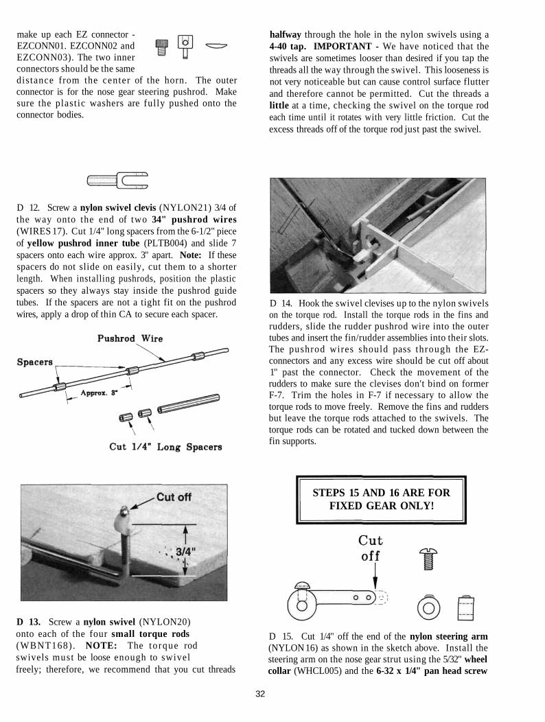
make up each EZ connector -EZCONN01. EZCONN02 andEZCONN03). The two innerconnectors should be the samedistance from the center of the horn. The outerconnector is for the nose gear steering pushrod. Makesure the plast ic washers are fully pushed onto theconnector bodies.
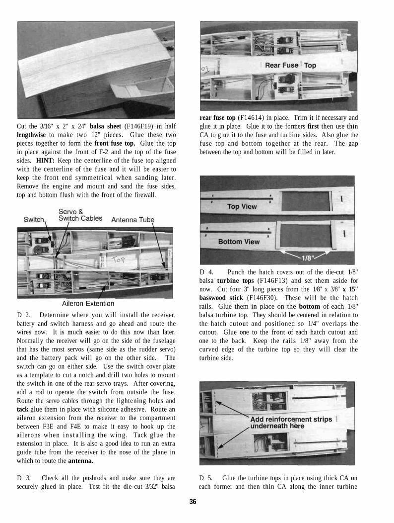
halfway through the hole in the nylon swivels using a4-40 tap. IMPORTANT - We have noticed that theswivels are sometimes looser than desired if you tap thethreads all the way through the swivel. This looseness isnot very noticeable but can cause control surface flutterand therefore cannot be permitted. Cut the threads alittle at a time, checking the swivel on the torque rodeach time until it rotates with very little friction. Cut theexcess threads off of the torque rod just past the swivel.
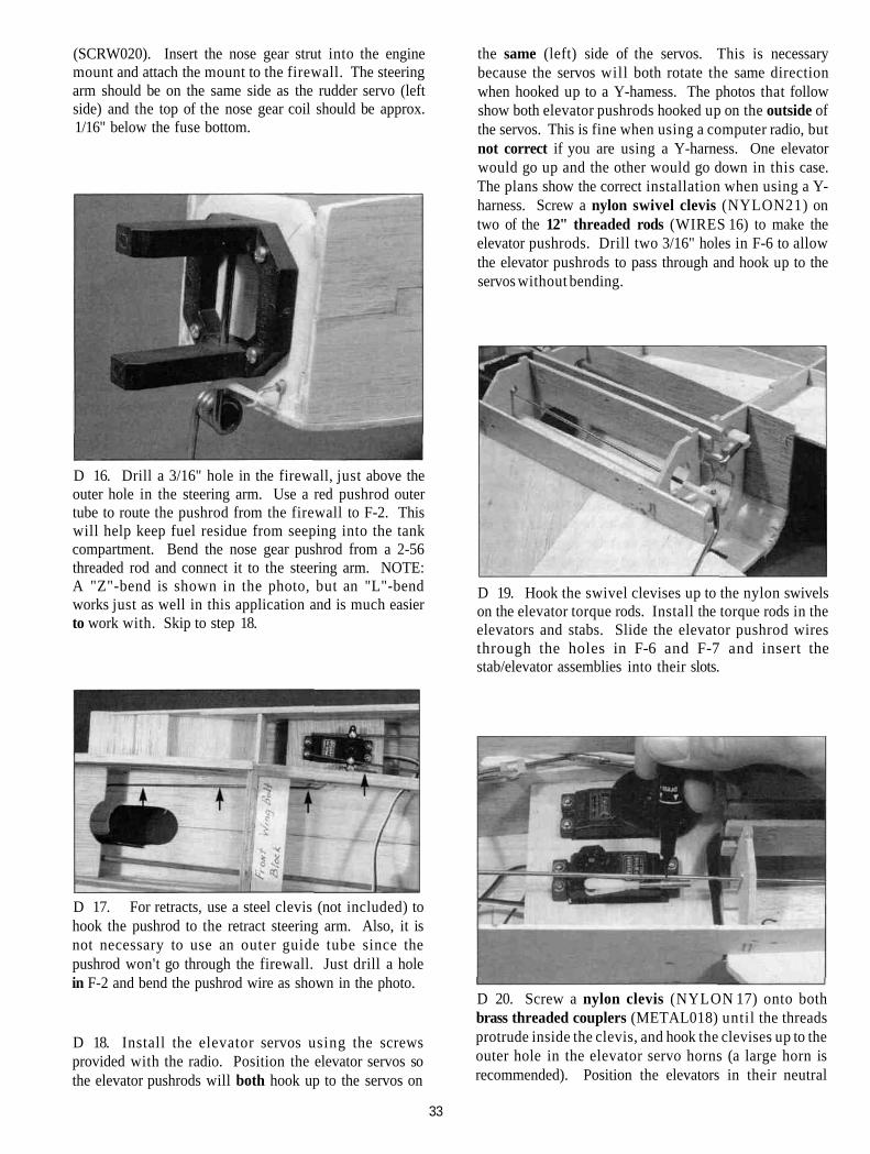
D 12. Screw a nylon swivel clevis (NYLON21) 3/4 ofthe way onto the end of two 34" pushrod wires(WIRES 17). Cut 1/4" long spacers from the 6-1/2" pieceof yellow pushrod inner tube (PLTB004) and slide 7spacers onto each wire approx. 3" apart. Note: If thesespacers do not slide on easily, cut them to a shorterlength. When installing pushrods, position the plasticspacers so they always stay inside the pushrod guidetubes. If the spacers are not a tight fit on the pushrodwires, apply a drop of thin CA to secure each spacer.
D 14. Hook the swivel clevises up to the nylon swivelson the torque rod. Install the torque rods in the fins andrudders, slide the rudder pushrod wire into the outertubes and insert the fin/rudder assemblies into their slots.The pushrod wires should pass through the EZ-connectors and any excess wire should be cut off about1" past the connector. Check the movement of therudders to make sure the clevises don't bind on formerF-7. Trim the holes in F-7 if necessary to allow thetorque rods to move freely. Remove the fins and ruddersbut leave the torque rods attached to the swivels. Thetorque rods can be rotated and tucked down between thefin supports.
D 13. Screw a nylon swivel (NYLON20)onto each of the four small torque rods(WBNT168) . NOTE: The torque rod swivels must be loose enough to swivelfreely; therefore, we recommend that you cut threads
STEPS 15 AND 16 ARE FORFIXED GEAR ONLY!
D 15. Cut 1/4" off the end of the nylon steering arm(NYLON 16) as shown in the sketch above. Install thesteering arm on the nose gear strut using the 5/32" wheelcollar (WHCL005) and the 6-32 x 1/4" pan head screw
32
(SCRW020). Insert the nose gear strut into the enginemount and attach the mount to the firewall. The steeringarm should be on the same side as the rudder servo (leftside) and the top of the nose gear coil should be approx.1/16" below the fuse bottom.
D 16. Drill a 3/16" hole in the firewall, just above theouter hole in the steering arm. Use a red pushrod outertube to route the pushrod from the firewall to F-2. Thiswill help keep fuel residue from seeping into the tankcompartment. Bend the nose gear pushrod from a 2-56threaded rod and connect it to the steering arm. NOTE:A "Z"-bend is shown in the photo, but an "L"-bendworks just as well in this application and is much easierto work with. Skip to step 18.
the same (left) side of the servos. This is necessarybecause the servos will both rotate the same directionwhen hooked up to a Y-hamess. The photos that followshow both elevator pushrods hooked up on the outside ofthe servos. This is fine when using a computer radio, butnot correct if you are using a Y-harness. One elevatorwould go up and the other would go down in this case.The plans show the correct installation when using a Y-harness. Screw a nylon swivel clevis (NYLON21) ontwo of the 12" threaded rods (WIRES 16) to make theelevator pushrods. Drill two 3/16" holes in F-6 to allowthe elevator pushrods to pass through and hook up to theservos without bending.
D 19. Hook the swivel clevises up to the nylon swivelson the elevator torque rods. Install the torque rods in theelevators and stabs. Slide the elevator pushrod wiresthrough the holes in F-6 and F-7 and insert thestab/elevator assemblies into their slots.
D 17. For retracts, use a steel clevis (not included) tohook the pushrod to the retract steering arm. Also, it isnot necessary to use an outer guide tube since thepushrod won't go through the firewall. Just drill a holein F-2 and bend the pushrod wire as shown in the photo.
D 18. Install the elevator servos using the screwsprovided with the radio. Position the elevator servos sothe elevator pushrods will both hook up to the servos on
D 20. Screw a nylon clevis (NYLON 17) onto bothbrass threaded couplers (METAL018) until the threadsprotrude inside the clevis, and hook the clevises up to theouter hole in the elevator servo horns (a large horn isrecommended). Position the elevators in their neutral
33

position and mark on the pushrod wires where to cutthem off (approx. 1/16" before the coupler tapers down).
have to file the comers of the engine mount rails to makeroom for the crankcase. If the mount would require alarge amount of filing, just replace the mount with onethat correctly fits your engine.
D 21. Remove the elevator pushrods from the fuselageand cut them oft at the mark. Remove the nylon clevisesfrom the threaded couplers and solder the couplers to thewires with acid core solder. After things cool down,replace the clevises and hook the pushrods up to theservos. Move each servo arm throughout its range andcheck the elevator movement for binding. Adjust theclevises until the elevators are at neutral when the servoarms are at neutral. Trim the holes in formers F-6 andF-7 if necessary to obtain clearance for the elevatorpushrods. Remove the stabs and elevators but leave thetorque rods attached to the swivels. The torque rods canbe rotated and tucked in between the stab supports.
D 1. Place the engine pointing straight ahead on themount (in the approximate location shown on the plans)and mark the mounting hole locations on the mount. Atthe marked locations, accurately dri l l 7/64" (or #36)holes. NOTE: If you have access to a drill press, use itfor drilling these holes to insure that they are drilledvertically.
D 2. Now you may use one of the following methodsto attach your engine to the mount:
Method 1: Screw the #6 x 3/4" sheet metal screws(provided in the kit) through theengine mounting flange and intothe mount. When first installingthese screws, put a drop of oilinto each screw hole.
Method 2: Cut threads into the holes you just drilledusing a 6-32 tap and tap wrench. If you use this method,you'll have to supply your own bolts (6-32 x 1" sockethead cap screws) for attaching the engine to the mount.
D 22. I n s t a l l the thro t t le servo u s i n g the screwsprovided with your radio. It should be installed in theremaining rear servo tray opening to help balance theairplane.
D 3. Attach the engine mount to the firewall using the6-32 x 5/8" cap screws.
DRILL ENGINE MOUNT(Great Planes MM60D90 or similar glass-filled nylonmount)
NOTE: If the engine mount supplied in the kit does notappear to fit your engine (example: OS .61 SF), you may
D 4. Screw your engine to the mount, and determinethe location where the throttle pushrod w i l l passthrough F-1. Due to the length of the throttle pushrod, aflexible plastic pushrod (not included) works well forthis. Drill a 3/16" hole (or whatever size you need) inthe firewall for the throttle pushrod guide tube. The holeshould be 1/4" away from the outside of the fuselage to
34

with the top surface of the fuse side. You can cut reliefslots in the triangle if needed to get it to bend easier.
allow room for the nose sides. Route the outer guidetube through the openings in the formers back to thethrottle servo. Drill any holes necessary to keep thepushrod as straight as possible. Cut the pushrod tolength and use nylon clevises and 1" threaded studs onboth ends. Sand the outside of all the plastic pushrodguide tubes with 100-grit sandpaper. Then glue them inplace.
D 3. Now remove all three retracts and fuelproof theinside of the fuel tank compartment and the area betweenF3E and F5E by brushing on a coat of polyester resin,finishing epoxy or other fuel proof paint. This will keepthe wood from getting fuel soaked and soft when residuegets blown or splashed in through the wheel wells.When this has cured, replace the retracts.
INSTALL FUEL TANK
D 1. Assemble your 10 oz. fuel tank. Werecommend using a Dubro 10 oz. tank and bending thebrass tubes as shown in the photo. This keeps the fuellines on the outside of the fuselage where they will beaccessible. Drill two 5/32" holes above the enginemount for the tubes to pass through the firewall. HINT:To avoid kinking the tubes when bending, we use K&STubing Bending Springs. Cut the brass tubes off sothey protrude approximately 1/2"- 3/4" past the firewall.
D 4. Replace the fuel tank and mark on the firewallwhich brass tube is which. Put an "F" next to the fueltube and a "V" next to the vent tube. Cut pieces of latexfoam rubber and place them on both sides of the fueltank to cushion the fuel tank from engine vibration.Apply silicone adhesive around the tubes to seal off theholes in the firewall. Cut a scrap piece of balsa to fitbehind the tank and glue it in to hold the tank in place.
D 2. Remove the tank and install two 10-1/2" longpieces of 1/2" balsa triangle (WSTR001H) along thetop edge of each fuse side. Bend the triangle to conform
FINAL FUSELAGE CONSTRUCTION
D 1. Sand the top surface of the fuse sides above thetank compartment with a sanding block.
35
Cut the 3/16" x 2" x 24" balsa sheet (F146F19) in halflengthwise to make two 12" pieces. Glue these twopieces together to form the front fuse top. Glue the topin place against the front of F-2 and the top of the fusesides. HINT: Keep the centerline of the fuse top alignedwith the centerline of the fuse and it will be easier tokeep the front end symmetrical when sanding later.Remove the engine and mount and sand the fuse sides,top and bottom flush with the front of the firewall.
Aileron ExtentionD 2. Determine where you will install the receiver,battery and switch harness and go ahead and route thewires now. It is much easier to do this now than later.Normally the receiver will go on the side of the fuselagethat has the most servos (same side as the rudder servo)and the battery pack will go on the other side. Theswitch can go on either side. Use the switch cover plateas a template to cut a notch and drill two holes to mountthe switch in one of the rear servo trays. After covering,add a rod to operate the switch from outside the fuse.Route the servo cables through the lightening holes andtack glue them in place with silicone adhesive. Route anaileron extension from the receiver to the compartmentbetween F3E and F4E to make it easy to hook up theailerons when i n s t a l l i n g the wing . Tack glue theextension in place. It is also a good idea to run an extraguide tube from the receiver to the nose of the plane inwhich to route the antenna.
D 3. Check all the pushrods and make sure they aresecurely glued in place. Test fit the die-cut 3/32" balsa
rear fuse top (F14614) in place. Trim it if necessary andglue it in place. Glue it to the formers first then use thinCA to glue it to the fuse and turbine sides. Also glue thefuse top and bottom together at the rear. The gapbetween the top and bottom will be filled in later.
D 4. Punch the hatch covers out of the die-cut 1/8"balsa turbine tops (F146F13) and set them aside fornow. Cut four 3" long pieces from the 1/8" x 3/8" x 15"basswood stick (F146F30). These will be the hatchrails. Glue them in place on the bottom of each 1/8"balsa turbine top. They should be centered in relation tothe hatch cutout and positioned so 1/4" overlaps thecutout. Glue one to the front of each hatch cutout andone to the back. Keep the rails 1/8" away from thecurved edge of the turbine top so they will clear theturbine side.
D 5. Glue the turbine tops in place using thick CA oneach former and then thin CA along the inner turbine
36

side. Cut two strips of 1/8" balsa approx. 3/8" wide and2-7/8" long (from scrap around the die-cut sheets). Gluethese strips underneath the front edge of each turbinetop to reinforce them.
5/64". Write on the front bottom of each hatch coverwhether it is the right or left cover so you can keep themstraight.
D 6. Use a sanding block with medium gritsandpaper to sand the edges of the turbine tops and outersides flush with the formers. Glue the two top 1/4" x1-3/8" x 27" balsa turbine corners (F146F21) in placejust as you did the bottom comers earlier.
Be careful to keep the turbine top flat around the hatcharea. The thin area around the hatch cut out will tend tobend down when you're sanding and it w i l l not getsanded correctly. Then when you apply the turbinecomer, it will be pushed down slightly and the hatch willnot line up with it. Rough sand the comers to the crosssections shown on the plans.
D 8. Put a drop of thin CA on each hatch cover holeand allow it to soak in and cure. Carefully countersinkeach hole so the flat head screws will be flush with thetop surface of the hatch cover. Test fitthe hatch covers using the #2 x 3/8" flathead sheet metal screws (SCRW069)provided.
FIT THE WING TO THE FUSE
D 7. Set the hatch covers in place in the hatchopenings and check their fit. They need to have a 1/32"gap on all four sides to allow for the covering. Sandthem if needed to get the correct fit. When satisfied withtheir fit, tape them in place to keep them from movingand drill 1/16" holes at each punch mark. Remove thehatch covers and enlarge the holes in the hatch only to
D 1. Gently sand the wing saddle smooth and thenset the wing in place with the top up. Check the fit ofthe wing strakes around the fuselage. They should fitvery close with no more than 1/32" of gap on both sides.Fill in any voids with either balsa or wood filler.
D 2. Use a T-pin and a piece of string to check thealignment of the wing. Stick the T-pin in the middle ofthe tail and loop the string around the pin. Pull the stringover to the joint formed between W 11 and the spar and
37

hold your finger there on the string. Swing the stringover to the other tip and compare the measurement.Adjust the wing if necessary and repeat this again untilthe measurements are equal. When they are equal, makea mark on the wing and the fuse so you can tell whenthey are aligned. Put a couple strips of masking tapealong the center TE and the turbine tops. Also wrap astrip of tape along the top of each strake and down ontothe inlets to help hold the wing in place.
These measurementsmust be equal! wing bolt blocks in the fuse. Drill the holes all the way
through the wing bolt plates and the top surface of thewing. IMPORTANT - Do not allow the wing to movewhile drilling!
D 5. Remove the wing and re-drill the holes in thewing only to 5/16". Enlarge the front hole in the bottomwing sheeting only to approx. 1/2" diameter so thesheeting doesn't get banged up when inserting the bolts.Also remove about a square inch of sheeting around thebolt hole on the top surface of the wing so you can workthere in the next step.
D 3. Securely glue the 1/16" x 1-1/4" x 3" ply rearwing bolt plate (F146W19) in place with thick CA. Itshould be centered in relation to F-4, and the back edgeof the wing bolt plate should be about 1/16" in front ofF-4. Be careful not to glue the wing to the fuse!
D 4. Check the alignment of the wing one more timeto be sure and then care fu l ly tu rn the plane over.Holding the wing firmly in place, drill a 1/4" hole in thecenter of each die-cut hole in the fuse bottom. Hold thefuselage level and keep the drill perpendicular to the
D 6. Use a pairof wire cutters tocut off the three"teeth" on the two1/4" blind nuts( N U T S 0 2 0 ) .NOTE: You can bend the teeth even with the flange ifyou don't want to cut them off. If you have a 1/4-20 tap,run it through the blind nut a couple of times from theun-flanged end to clean up the threads. Roughen theflange of the blind nuts with sandpaper to help the glue
38
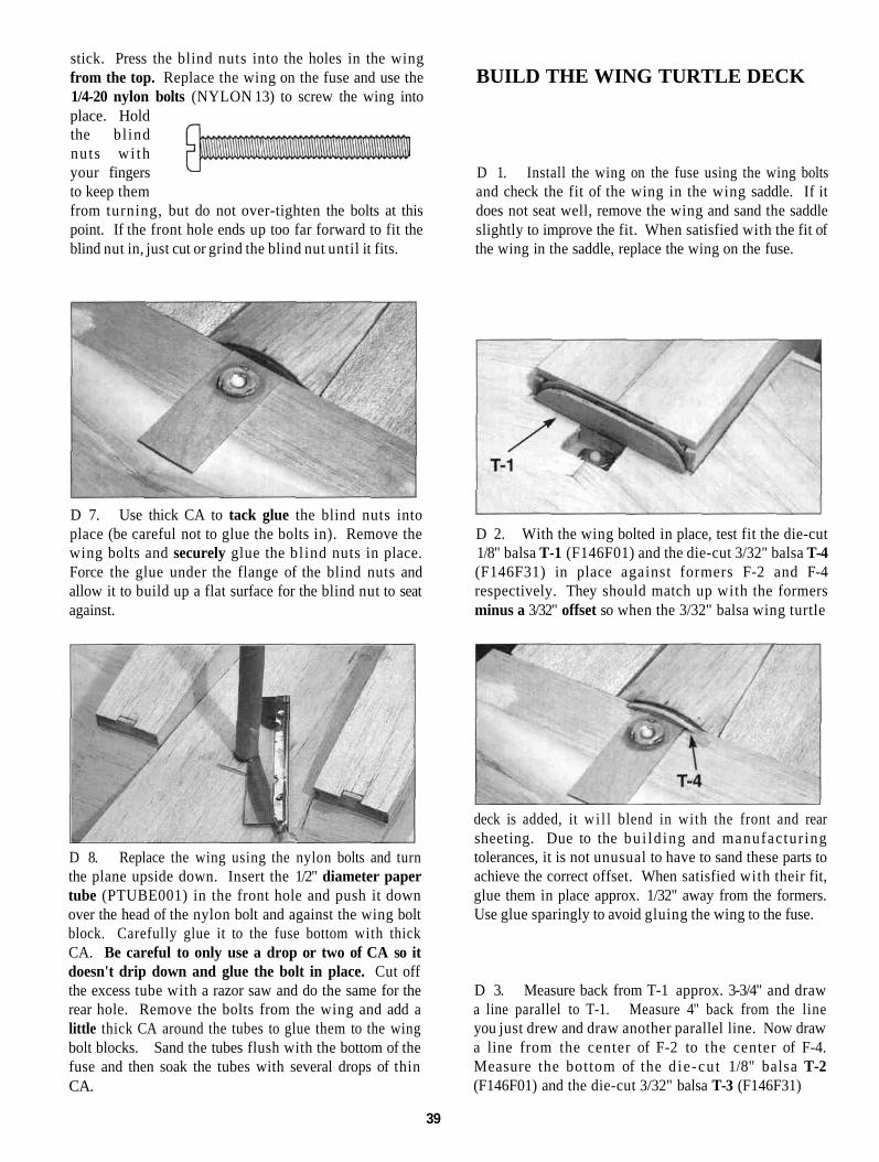
stick. Press the blind nuts into the holes in the wingfrom the top. Replace the wing on the fuse and use the1/4-20 nylon bolts (NYLON 13) to screw the wing intoplace. Holdthe bl indnuts wi thyour fingersto keep themfrom turning, but do not over-tighten the bolts at thispoint. If the front hole ends up too far forward to fit theblind nut in, just cut or grind the blind nut until it fits.
BUILD THE WING TURTLE DECK
D 1. Install the wing on the fuse using the wing boltsand check the fit of the wing in the wing saddle. If itdoes not seat well, remove the wing and sand the saddleslightly to improve the fit. When satisfied with the fit ofthe wing in the saddle, replace the wing on the fuse.
D 7. Use thick CA to tack glue the blind nuts intoplace (be careful not to glue the bolts in). Remove thewing bolts and securely glue the blind nuts in place.Force the glue under the flange of the blind nuts andallow it to build up a flat surface for the blind nut to seatagainst.
D 2. With the wing bolted in place, test fit the die-cut1/8" balsa T-1 (F146F01) and the die-cut 3/32" balsa T-4(F146F31) in place against formers F-2 and F-4respectively. They should match up with the formersminus a 3/32" offset so when the 3/32" balsa wing turtle
D 8. Replace the wing using the nylon bolts and turnthe plane upside down. Insert the 1/2" diameter papertube (PTUBE001) in the front hole and push it downover the head of the nylon bolt and against the wing boltblock. Carefully glue it to the fuse bottom with thickCA. Be careful to only use a drop or two of CA so itdoesn't drip down and glue the bolt in place. Cut offthe excess tube with a razor saw and do the same for therear hole. Remove the bolts from the wing and add alittle thick CA around the tubes to glue them to the wingbolt blocks. Sand the tubes flush with the bottom of thefuse and then soak the tubes with several drops of thinCA.
deck is added, it wi l l blend in with the front and rearsheeting. Due to the bu i ld ing and manufactur ingtolerances, it is not unusual to have to sand these parts toachieve the correct offset. When satisfied with their fit,glue them in place approx. 1/32" away from the formers.Use glue sparingly to avoid gluing the wing to the fuse.
D 3. Measure back from T-1 approx. 3-3/4" and drawa line parallel to T-1. Measure 4" back from the lineyou just drew and draw another parallel line. Now drawa line from the center of F-2 to the center of F-4.Measure the bottom of the d ie -cu t 1/8" balsa T-2(F146F01) and the die-cut 3/32" balsa T-3 (F146F31)
39

and mark the center of each of these. Glue T-2 and T-3on the parallel lines you just drew so their center mark ison the centerline of the wing.
D 4. Test fit the two halves of the die-cut 3/32" balsawing turtle deck sheeting (F146F31) together. Sandthem if necessary to achieve a good joint between thetwo. Glue them together with thin CA and then sandboth sides smooth. Wet one side of the sheeting with adamp sponge or paper towel and allow the water to soakin for 5 minutes or so.
D 5. Remove the wing from the fuse and center theturtle deck sheeting on T-l and T-4. Carefully bend itinto place to check its fit. It will probably need a littletrimming to make it fit well. First trim it to fit T-l andT-4 and then check its fit on T-2 and T-3. NOTE: Whenfitting the sheeting, trim equally on each side to keep itsymmetrical. This can be tricky to get just right, so don'tget in a hurry, take your time and trim a little at a time.If you end up with gaps, just fi l l them with model filler.Check to make sure you can see the parallel lines youdrew earlier when the sheeting is in place. If not,lengthen them. The edges of the turtle deck sheetingshould "flow" from the shape of the fuse front into theshape of the rear fuse top.
D 6. When satisfied with the fit. glue it in place byfirst correctly positioning it, then adding thin CA at the
center of T-l and T-4. Allow the glue to cure, then workit down into place a little at a time on one side and thenthe other until it is completely attached to T-l and T-4.Now poke a few holes with a pin where T-2 and T-3 are(use the parallel lines as a guide) and apply a coupledrops of thin CA to each hole. Press the sheeting downagainst T-2 and T-3 while the glue is curing. Glue theedges down with thin CA.
D 7. Test fit the wing in place again and trim theturtle deck sheeting so the wing w i l l have enoughclearance to fit on and off easily (approx. 1/32" at bothends). Don't worry if the turtle deck doesn't match upperfectly with the fuselage, we will use model filler laterto smooth things out.
ENGINE COMPARTMENT
D 1. Attach the engine mount to F-l, and attach theengine to the mount. Remove the nose gear from theengine mount. Mark the outline of the engine mount onthe firewall with a pencil.
D 2. From a scrap of 1/16" balsa, cut four smallpieces and tack glue them to the 1/16" ply spinner ring(US40F02) as shown, using a very small amount of thickCA (these wil l be removed later). IMPORTANTNOTE: Due to the small engine compartment, shockabsorbing engine mounts that allow the engine to moveare not recommended.
40
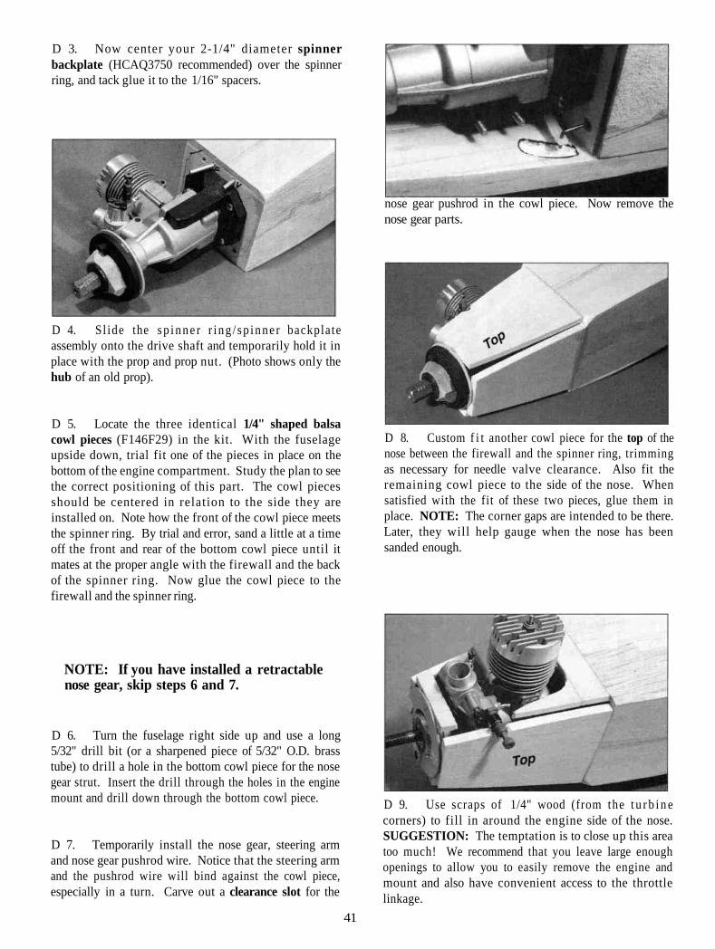
D 3. Now center your 2-1/4" diameter spinnerbackplate (HCAQ3750 recommended) over the spinnerring, and tack glue it to the 1/16" spacers.
D 4. Sl ide the s p i n n e r r i ng / sp inne r backplateassembly onto the drive shaft and temporarily hold it inplace with the prop and prop nut. (Photo shows only thehub of an old prop).
D 5. Locate the three identical 1/4" shaped balsacowl pieces (F146F29) in the kit. With the fuselageupside down, trial fit one of the pieces in place on thebottom of the engine compartment. Study the plan to seethe correct positioning of this part. The cowl piecesshould be centered in relation to the side they areinstalled on. Note how the front of the cowl piece meetsthe spinner ring. By trial and error, sand a little at a timeoff the front and rear of the bottom cowl piece until itmates at the proper angle with the firewall and the backof the spinner ring. Now glue the cowl piece to thefirewall and the spinner ring.
nose gear pushrod in the cowl piece. Now remove thenose gear parts.
D 8. Custom f i t another cowl piece for the top of thenose between the firewall and the spinner ring, trimmingas necessary for needle valve clearance. Also fit theremaining cowl piece to the side of the nose. Whensatisfied with the fit of these two pieces, glue them inplace. NOTE: The corner gaps are intended to be there.Later, they will help gauge when the nose has beensanded enough.
NOTE: If you have installed a retractablenose gear, skip steps 6 and 7.
D 6. Turn the fuselage right side up and use a long5/32" drill bit (or a sharpened piece of 5/32" O.D. brasstube) to drill a hole in the bottom cowl piece for the nosegear strut. Insert the drill through the holes in the enginemount and drill down through the bottom cowl piece.
D 7. Temporarily install the nose gear, steering armand nose gear pushrod wire. Notice that the steering armand the pushrod wire will bind against the cowl piece,especially in a turn. Carve out a clearance slot for the
D 9. Use scraps of 1/4" wood (from the t u r b i n ecorners) to fill in around the engine side of the nose.SUGGESTION: The temptation is to close up this areatoo much! We recommend that you leave large enoughopenings to allow you to easily remove the engine andmount and also have convenient access to the throttlelinkage.
41

D 10. Remove the prop nut and propeller. Carefullypop the spinner backplate loose with a screwdriver andremove the spacers. Remove the engine and mount inpreparation for the next steps. You may have to cut awaysome of the scrap wood you just installed to get theengine out. This is ok, you have to be able to service theengine.
D 11. Check the fuel tank brass tubes and cut outaround them if necessary so the fuel tubing will slide onlater. If necessary, carve out the area of the nose side ifneeded for the nose gear steering arm and pushrodclearance. D 15. Using a razor plane and a sanding block with
coarse sandpaper, rough sand the front of the fuselage asshown above. The nose should be perfectly round at thespinner ring and flow smoothly to the cross sectionsshown on the plans at the firewall and F-2. The bottomcomers should become sharper as they near the inlets andflow smoothly into the fuse bottom. Do not sand belowthe wing outline you drew or you will increase the winggap.
D 16. Now, with the engine and mount removed,fuelproof the inside of the entire engine compartmentwith polyester resin or epoxy thinned with alcohol.
D 12. From the 1/2" balsa t r iangle stock(WSTR001H), cut lengths to fit in all the corners of thenose, between the firewall and the spinner ring. Addthick CA around the inside of the spinner ring and thefront of the firewall to secure everything.
D 13. Trim the triangle stock as needed to temporarilyre-install the engine and mount. Trim the cowl bottom asnecessary to get the muffler on the engine. Trim thecowl to allow a 1/8" gap around all engine partsincluding the muffler. When satisfied with the clearance,remove the engine and mount.
D 14. Set the wing on the fuse and draw a line alongthe top surface of the wing on the side of the fuselage.Do this on both sides of the fuse. Remove the wing.
FINAL ASSEMBLY
D 1. From the 1/16" x 3/8" x 30" balsa sticks(F146W20) cut the cap strips to fit between the leadingedge sheeting and the trai l ing edge sheeting and gluethem in place over each rib. Do this for both sides of allthe ribs. HINT - For easier positioning of the cap strips,first mark the location of the ribs on the LE and TEsheeting.
42

D 2. Sand the outside of each W11 to obtain a squareand flat surface to attach the wing tips. Also sand the TEsheeting flush with the TE.
D 3. Lay each tapered balsa aileron (F146W08)over the plan with the tip extending approximately 1"past rib W11. Cut the aileron end off at the angle shownon the plans. Lay the wing over the plan and make amark on the TE'S where the inner edge of each aileronend should go.
D 2. Line the centerline of each wing tip up with thecenterline of each rib W11 and securely glue them inplace. IMPORTANT - The aft edge of the wing tipblock must be approximately 5/8" behind the aileron endTE, to allow for wing sweep.
D 4. Tape the aileron ends in place with maskingtape so the slanted edges line up with the marks on theTE. Check the alignment of the aileron ends with theairfoil contour at rib W11. It is of utmost importancethat they are correctly aligned and do not tip up or down.Also look along the trailing edge of the aileron end tomake sure it is pointing at the center TE. When satisfiedwith their alignment, glue them in place with thin CA.Remove the tape and add thick CA if needed to fill anygaps. Cut and sand the outer end flush with rib W11.
D 3. Use a razor plane and coarse grit sandpaper tocarve and sand the wing tips to the appropriate shape asshown in the photo and on the plans. Blend the tips withthe top and bottom surfaces of the wing and with thetapered aileron piece. NOTE: Do not sand the TE ofthe tip to a sharp edge, as it will be too fragile. Instead,leave it approximately 1/16" thick. You can put a strip ofmasking tape around rib W11 to keep from sanding itduring this step.
D 4. Soak the trailing and outer edges of each wingtip with thin CA and allow it to cure. This will hardenthe wood and help protect it from dings.
INSTALL WING TIPS
D 1. Draw a centerline on the outer surface of W11(from the front of the LE to the TE of the aileron end)and all the way around each wing tip. This will help youinstall them correctly and sand them symmetrically.
INSTALL AILERONS
NOTE: Do not glue the aileron hinges until after yourmodel has been covered.
D 1. Draw an accurate centerline along the LE of thetapered balsa ailerons and the wing TE.
43

0 2. Check the length of your ailerons against theactual ai leron openings and trim the ailerons asnecessary. You should provide approximately 1/16" gapat each end of the ailerons.
D 3. Lay the ailerons in place in the openings, withthe torque rods resting on top of the ailerons. Mark thetorque rod locations on the top of the ailerons. Markthe inside end of each aileron with an "L" for the left oneand an "R" for the right one.
D 8. Sand the leading edge of the ailerons to the same"V"-shape as shown on the wing rib detail drawing.Round off the sharp comers on the top and bottom of theaileron as show.
D 9. Insert the hinges into the slots and trial fit theailerons in place on the wing. Do not glue the hingesuntil after you have covered the wing. Sand the inside,TE corner of each aileron at an angle to match up withthe center TE as shown on the plans.
THERE SHOULD BE NO HINGE GAP!
D 4. Drill a 1/8" hole in the ailerons at the torque rodlocations, starting at the leading edge centerline anddrilling straight in to the proper depth.
INSTALL AILERON SERVO
D 5. Use a sharpened 1/8" diameter brass tube to cuta groove in the leading edge of the ailerons to acceptthe torque rods. Trial fit the ailerons onto the torque rodsand cut or file the groove as necessary until they fit.
D 6. Lay the ailerons on the plan and mark the hingelocations on the ailerons. Place the ailerons against thewing TE and transfer the marks over to the wing.
D 7. Cut the hinge slots in the ailerons and wing TEusing an X-acto knife, following the procedure andcautions on page 9.
D 1. Cut the sheeting away for the aileron servobetween the Wl ribs and behind the main spars on thebottom of the wing. The opening should extend to theback of the rear servo rail you installed earlier. Test fityour servo in place on the rails and cut out the top wingsheeting if needed to allow the servo to sit on the rails.CAUTION: Do not cut into any wing spars!
D 2. Use the aileron servo to determine where todrill the mounting holes. Drill the holes with a 1/16"diameter bit and mount the servo using the screwsprovided with your radio. Remove the servo and put adrop of thin CA on each mounting hole in the rails andallow the glue to cure. Remount the servo and install alarge "X" type servo horn.
44

D 3. Dril l out the nylonaileron connectors (NYLON 10)with a 7/64" drill bit and cutthreads in them using a 6-32 tap.Screw the connectors onto the aileron torque rods untilthe highest holes are approximately 5/8" above the wingsheeting.
D 4. Screw a nylon clevis(NYLON17) onto the tworemaining 12" threaded pushrod wires (WIRES 17)until the threads are exposed inside the clevis.
INSTALL EXHAUST NOZZLES
D 5. Attach the clevises to the aileron connectors.Then, with the ailerons in the neutral position, mark thepushrod wires where they cross the holes in the servohorn. Remove the pushrods and make a "Z-bend" in therods at that point.
D 1. Use a medium or fine grit sanding block to finalshape the fuselage comers. First sand the turbine sides,top and bottom to bring the corners flush with the edges.Then sand the corners so they blend smoothly with thesides. Now draw a line all around the turbine 3/8"forward of the back edge of the fuse. Sand the woodbehind this line to taper it a little more than the rest. Thiswill help you get the exhaust nozzles on.
D 2. Cut a 1/16" wide notch between the fusetop/bottom and the turbine inner side and top. It shouldbe about 1/2" deep as shown in the photo at step 1 toclear the nozzles.
D 6. Remove the servo horn from the servo and workthe Z-bends into the wheel. NOTE: You may have toenlarge the servo wheel holes with a 5/64" diameter drillbit. Replace the servo horn and check the operation ofthe ailerons. Enlarge the notches in the center wedgeand the TE'S if required to achieve full aileron throw(See page 55 for the recommended amount of aileronmovement).
D 3. Cut the ABS exhaust nozzles (F146F24) out oftheir bases by carefully trimming along the bottom scribeline. Do not cut the tip off yet. Put a full sheet of finegrit sandpaper on the work surface and slowly drag theexhaust nozzles across it to sand the edges smooth. Alsolightly sand the inside of the nozzles where they willglue to the wood (about 1/2") with fine sandpaper.
D 7. Final sand the entire surface of the wing using asanding block with fine sand paper. The LE crosssection at the front of the strakes is shown on the fuseside view. On the swept back portion of the strakes, theLE should gradually taper from the sharper cross sectionat the front to the normal cross section at rib W5.NOTE: The strake LE shape is very important, so try toachieve the shapes shown on the plan.
D 4. Notice that the nozzles have one comer that issharper than the other three. This corner goes up andtoward the center of the fuselage. Test fit the exhaustnozzles in place. Do not force them into place or youmay crack them. They need to slip over the fuselageapproximately 3/8". Sand the fuse if necessary toachieve a good fit. Test fit both nozzles at the same time
45

so you can compare how they fit in relation to each other.They should both be located the same distance forwardand when compared from the side and above, they shouldbe aligned with each other.
CUT THE MAIN GEAR RETRACTOPENINGS
The retract openings are made using a fit and cut type ofoperation that will take a little time but is not hard to do.
D D 1. Insert the right main gear strut in the rightside retract to the proper depth and tighten the set screw.This is tough to do because the ball driver is way downinside, but it can be done. A long nose pliers may comein handy.
D D 2. Retract the strut until it hits the edge of theopening and notice where it touches the wood. Cut asmall notch there and allow the strut to retract a littlefarther. Make another small notch and allow the strut toretract a little farther. A Dremel tool with a small carbidegrinder will make this process much easier.
D 5. When satisfied with the fit of the nozzles, rotatethe rudder and elevator torque rods and insert them in thef in and stab slots so they w i l l be out of the way.Correctly position the nozzles and then add thin CAaround the edges of the nozzles.
D 6. Cut the tips off both nozzles by trimming themalong the scribe line and then l ightly sanding them tomatch each other in length. Save the tips to test paintand iron temperatures on later. NOTE: If you prefer alarger outlet in the tail cones, you can trim and sand themcloser to the fuselage. Add thick CA around the insideof each nozzle where the fuse wood stops.
D 7. Insert the fins, stabs and die-cut 1/8" ply ventralfins (F146F32) into their appropriate slots. Sand the finsand stabs if necessary to get them to fit all the way downinto the slots. Install the torque rods in the fins andstabs. Carefully trim the ABS nozzles if needed to getthese items to fit. IMPORTANT - When trimming thenozzles, do not leave any "corners" in the cut outs.Always make nice circular cuts and sand the edges of thecut with fine sandpaper. A corner will eventually allow astress crack to form. While these surfaces are inserted inthe fuselage, lightly draw a line on the fins, stabs andventral fins marking where the fuse joint is. This willtell us how far to cover these surfaces later. The nozzlescan be painted after the plane has been covered
D 8. Use scraps of wood and lightweight wood fillerto fill in between the rear of the fuse top and the fusebottom. Use the filler to blend the exhaust nozzles intothe fuse and sand this area smooth.
D D 3. Continue this process until the strut can fullyretract into the fuselage. Install a 2-1/4" wheel on thestrut and perform the same type of fit and cut procedureuntil the wheel will fit into the fuselage.
D D 4. Careful ly trim the edges of the retractopening to smooth them out and make them look niceand symmetrical. A Dremel tool with a small sandingdrum or a fine grit carbide drum works well for this.
46
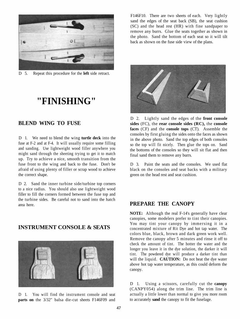
D 5. Repeat this procedure for the left side retract.
"FINISHING"
F146F10. There are two sheets of each. Very lightlysand the edges of the seat back (SB), the seat cushion(SC) and the head rest (HR) with fine sandpaper toremove any burrs. Glue the seats together as shown inthe photo. Sand the bottom of each seat so it will tiltback as shown on the fuse side view of the plans.
BLEND WING TO FUSE
D 1. We need to blend the wing turtle deck into thefuse at F-2 and at F-4. It will usually require some fillingand sanding. Use lightweight wood filler anywhere youmight sand through the sheeting trying to get it to matchup. Try to achieve a nice, smooth transition from thefuse front to the wing and back to the fuse. Don't beafraid of using plenty of filler or scrap wood to achievethe correct shape.
D 2. Sand the inner turbine side/turbine top cornersto a nice radius. You should also use lightweight woodfiller to fill the corners formed between the fuse top andthe turbine sides. Be careful not to sand into the hatcharea here.
INSTRUMENT CONSOLE & SEATS
D 1. You will find the instrument console and seatparts on the 3/32" balsa die-cut sheets F146F09 and
D 2. Lightly sand the edges of the front consolesides (FC), the rear console sides (RC), the consolefaces (CF) and the console tops (CT). Assemble theconsoles by first gluing the sides onto the faces as shownin the above photo. Sand the top edges of both consolesso the top will fit nicely. Then glue the tops on. Sandthe bottoms of the consoles so they will sit flat and thenfinal sand them to remove any burrs.
D 3. Paint the seats and the consoles. We used flatblack on the consoles and seat backs with a militarygreen on the head rest and seat cushion.
PREPARE THE CANOPYNOTE: Although the real F-14's generally have clearcanopies, some modelers prefer to t int their canopies.You may tint your canopy by immersing it in aconcentrated mixture of Rit Dye and hot tap water. Thecolors blue, black, brown and dark green work well.Remove the canopy after 5 minutes and rinse it off tocheck the amount of tint. The hotter the water and thelonger you leave it in the dye solution, the darker it willtint. The powdered dye will produce a darker tint thanwill the liquid. CAUTION: Do not heat the dye waterabove hot tap water temperature, as this could deform thecanopy.
D 1. Using a scissors, carefully cut the canopy(CANPY054) along the trim line. The trim line isactually a little lower than normal to give you more roomto accurately sand the canopy to fit the fuselage.
47
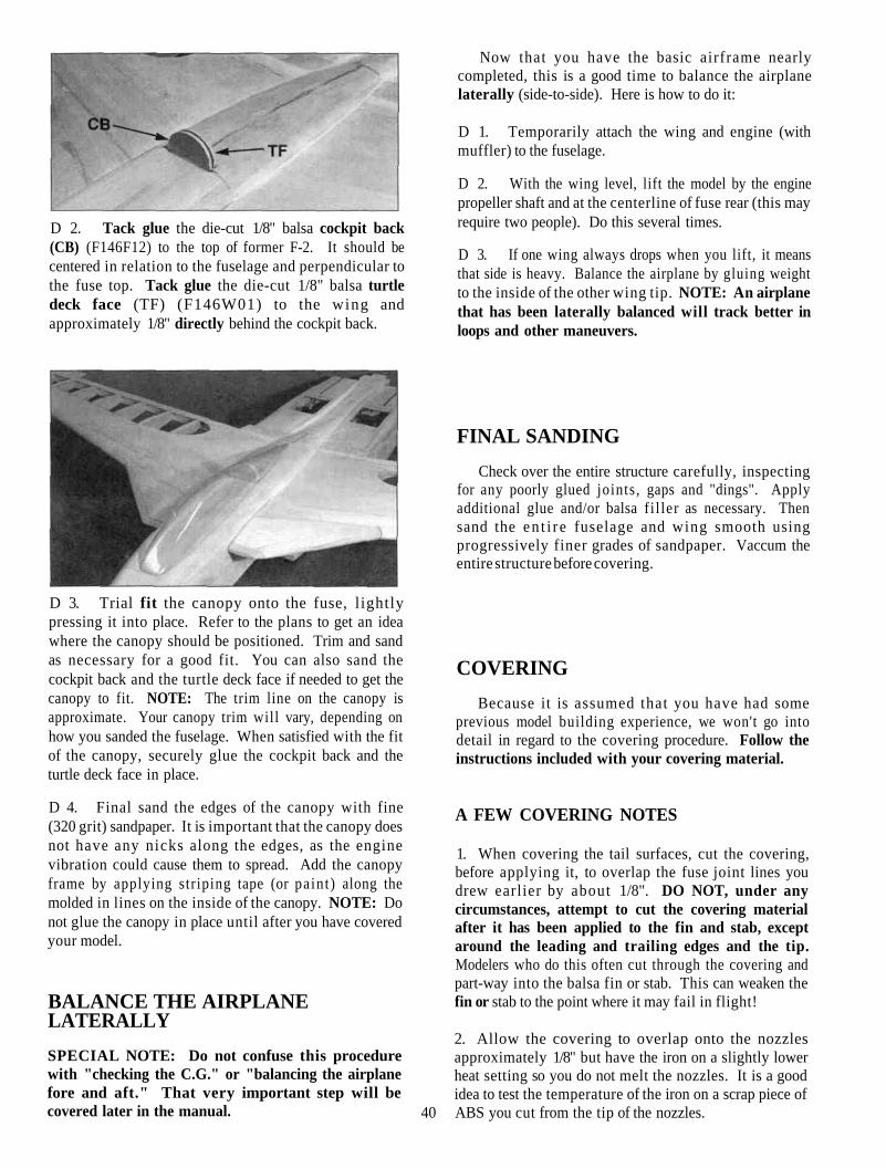
D 2. Tack glue the die-cut 1/8" balsa cockpit back(CB) (F146F12) to the top of former F-2. It should becentered in relation to the fuselage and perpendicular tothe fuse top. Tack glue the die-cut 1/8" balsa turtledeck face (TF) (F146W01) to the wing andapproximately 1/8" directly behind the cockpit back.
Now that you have the basic airframe nearlycompleted, this is a good time to balance the airplanelaterally (side-to-side). Here is how to do it:
D 1. Temporarily attach the wing and engine (withmuffler) to the fuselage.
D 2. With the wing level, lift the model by the enginepropeller shaft and at the centerline of fuse rear (this mayrequire two people). Do this several times.
D 3. If one wing always drops when you lift, it meansthat side is heavy. Balance the airplane by gluing weightto the inside of the other wing tip. NOTE: An airplanethat has been laterally balanced will track better inloops and other maneuvers.
FINAL SANDINGCheck over the entire structure carefully, inspecting
for any poorly glued joints, gaps and "dings". Applyadditional glue and/or balsa f i l ler as necessary. Thensand the en t i re fuselage and wing smooth usingprogressively finer grades of sandpaper. Vaccum theentire structure before covering.
D 3. Trial fit the canopy onto the fuse, lightlypressing it into place. Refer to the plans to get an ideawhere the canopy should be positioned. Trim and sandas necessary for a good fit. You can also sand thecockpit back and the turtle deck face if needed to get thecanopy to fit. NOTE: The trim line on the canopy isapproximate. Your canopy trim will vary, depending onhow you sanded the fuselage. When satisfied with the fitof the canopy, securely glue the cockpit back and theturtle deck face in place.
D 4. Final sand the edges of the canopy with fine(320 grit) sandpaper. It is important that the canopy doesnot have any nicks along the edges, as the enginevibration could cause them to spread. Add the canopyframe by applying striping tape (or paint) along themolded in lines on the inside of the canopy. NOTE: Donot glue the canopy in place until after you have coveredyour model.
BALANCE THE AIRPLANELATERALLYSPECIAL NOTE: Do not confuse this procedurewith "checking the C.G." or "balancing the airplanefore and aft." That very important step will becovered later in the manual.
COVERINGBecause it is assumed that you have had some
previous model building experience, we won't go intodetail in regard to the covering procedure. Follow theinstructions included with your covering material.
A FEW COVERING NOTES
1. When covering the tail surfaces, cut the covering,before applying it, to overlap the fuse joint lines youdrew earlier by about 1/8". DO NOT, under anycircumstances, attempt to cut the covering materialafter it has been applied to the fin and stab, exceptaround the leading and trailing edges and the tip.Modelers who do this often cut through the covering andpart-way into the balsa fin or stab. This can weaken thefin or stab to the point where it may fail in flight!
2. Allow the covering to overlap onto the nozzlesapproximately 1/8" but have the iron on a slightly lowerheat setting so you do not melt the nozzles. It is a goodidea to test the temperature of the iron on a scrap piece of
40 ABS you cut from the tip of the nozzles.
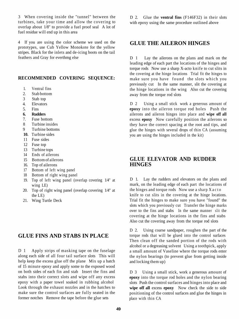
3 When covering inside the "tunnel" between theturbines, take your t ime and allow the covering tooverlap about 1/8" to provide a fuel proof seal A lot offuel residue will end up in this area
4 If you are using the color scheme we used on theprototypes, use Cub Yellow Monokote for the yellowstripes. Black for the inlets and de-icing boots on the tailfeathers and Gray for everthmg else
RECOMMENDED COVERING SEQUENCE:
1. Ventral fins2. Stab bottom3 Stab top4. Elevators5. Fins6. Rudders7. Fuse bottom8 Turbine insides9 Turbine bottoms10. Turbine sides11 Fuse sides12 Fuse top13 Turbine tops14 Ends of ailerons15 Bottom of ailerons16. Top of ailerons17 Bottom of left wing panel18 Bottom of right wing panel19. Top of left wing panel (overlap covering 1/4" at
wing LE)20. Top of right wing panel (overlap covering 1/4" at
the LE)21. Wing Turtle Deck
GLUE FINS AND STABS IN PLACE
D 1 Apply strips of masking tape on the fuselagealong each side of all four tail surface slots This willhelp keep the excess glue off the plane Mix up a batchof 15 minute epoxy and apply some to the exposed woodon both sides of each fin and stab Insert the fins andstabs into their correct slots and wipe off any excessepoxy with a paper towel soaked in rubbing alcoholLook through the exhaust nozzles and in the hatches tomake sure the control surfaces are fully seated in theformer notches Remove the tape before the glue sets
D 2. Glue the ventral fins (F146F32) in their slotswith epoxy using the same procedure outlined above
GLUE THE AILERON HINGES
D 1 Lay the ailerons on the plans and mark on theleading edge of each part the locations of the hinges andtorque rods Now use a sharp X-acto knife to cut slits inthe covering at the hinge locations Trial fit the hinges tomake sure you have f o u n d the slots w h i c h youpreviously cut In the same manner, slit the covering atthe hinge locations in the wing Also cut the coveringaway from the torque rod slots
D 2 Using a small stick work a generous amount ofepoxy into the aileron torque rod holes Push theailerons and aileron hinges into place and wipe off allexcess epoxy Now carefully position the ailerons sothey have the correct spacing at the root and tips, andglue the hinges with several drops of thin CA (assumingyou are using the hinges included in the kit)
GLUE ELEVATOR AND RUDDERHINGES
D 1. Lay the rudders and elevators on the plans andmark, on the leading edge of each part the locations ofthe hinges and torque rods Now use a sharp X a c t oknife to cut slits in the covering at the hinge locations.Trial fit the hinges to make sure you have "found" theslots which you previously cut Transfer the hinge marksover to the fins and stabs In the same manner s l i t thecovering at the hinge locations in the fins and stabsAlso cut the covering away from the torque rod slots
D 2. Using coarse sandpaper, roughen the part of thetorque rods that will be glued into the control surfacesThen clean off the sanded portion of the rods withalcohol or a degreasing solvent Using a toothpick, applya small amount of Vaseline where the torque rods enterthe nylon bearings (to prevent glue from getting insideand locking them up)
D 3 Using a small stick, work a generous amount ofepoxy into the torque rod holes and the nylon bearingslots Push the control surfaces and hinges into place andwipe off all excess epoxy Now check the side to sidepositioning of the control surfaces and glue the hinges inplace with thin CA
49
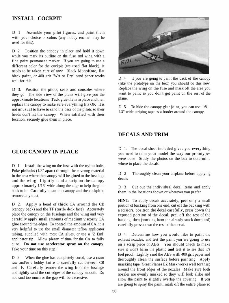
INSTALL COCKPIT
D 1 Assemble your pilot figures, and paint themwith your choice of colors (any hobby enamel may beused for this).
D 2. Position the canopy in place and hold it downwhile you mark its outline on the fuse and wing with afine point permanent marker If you are going to use adifferent color for the cockpit (we used flat black), itneeds to be taken care of now Black MonoKote, flatblack paint, or 400 grit "Wet or Dry" sand paper workswell for this
D 3. Position the pilots, seats and consoles wherethey go The side view of the plans will give you theapproximate locations Tack glue them in place and thenreplace the canopy to make sure everything fits OK It isnot unusual to have to sand the base of the pilots so theirheads don't hit the canopy When satisfied with theirlocation, securely glue them in place.
D 4 It you are going to paint the back of the canopy(like the prototype on the box) you should do this now.Replace the wing on the fuse and mask oft the area youwant to paint so you don't get paint on the rest of theplane.
D 5. To hide the canopy glue joint, you can use 1/8" -1/4" wide striping tape as a border around the canopy.
DECALS AND TRIM
GLUE CANOPY IN PLACE
D 1 Install the wing on the fuse with the nylon bolts.Poke pinholes (1/8" apart) through the covenng materialin the area where the canopy will be glued to the fuselageand the wing Light ly sand a strip on the canopyapproximately 1/16" wide along the edge to help the gluestick to it. Carefully clean the canopy and the cockpit toremove any dust.
D 2. Apply a bead of thick CA around the CB(canopy back) and the TF (turtle deck face) Accuratelyplace the canopy on the fuselage and the wing and verycarefully apply small amounts of medium viscosity CAglue around the edges To control the amount of CA, it isvery helpful to use the small diameter teflon applicatortubing, supplied with most CA glues, or use a "Z End"applicator tip Allow plenty of time for the CA to fullycure Do not use accelerator spray on the canopy.Take your time on this step!
D 3 When the glue has completely cured, use a razorsaw and/or a hobby knife to carefully cut between CBand TF. Carefully remove the wing from the fuselageand lightly sand the cut edges of the canopy smooth. Donot sand too much or the gap will be excessive.
D 1. The decal sheet included gives you everythingyou need to trim your model the way our prototypeswere done Study the photos on the box to determinewhere to place the decals.
D 2 Thoroughly clean your airplane before applyingdecals
D 3 Cut out the individual decal items and applythem in the locations shown or wherever you prefer
HINT: To apply decals accurately, peel only a smallportion of backing from one end, cut off the backing witha scissors, position the decal carefully, press down theexposed portion of the decal, peel off the rest of thebacking, then (working from the already stuck down end)carefully press down the rest of the decal.
D 4. Determine how you would like to paint theexhaust nozzles, and test the paint you are going to useon a scrap piece of ABS You should check to makesure it won't harm the plastic and test it to see that it'sfuel proof. Lightly sand the ABS with 400 grit paper andthoroughly clean the surface before painting Applymasking tape (Great Planes EZ Mask works well tor this)around the front edges of the nozzles Make sure bothnozzles are evenly masked so they will look alike andallow the paint to slightly overlap the covering If youare going to spray the paint, mask oft the entire plane so
50
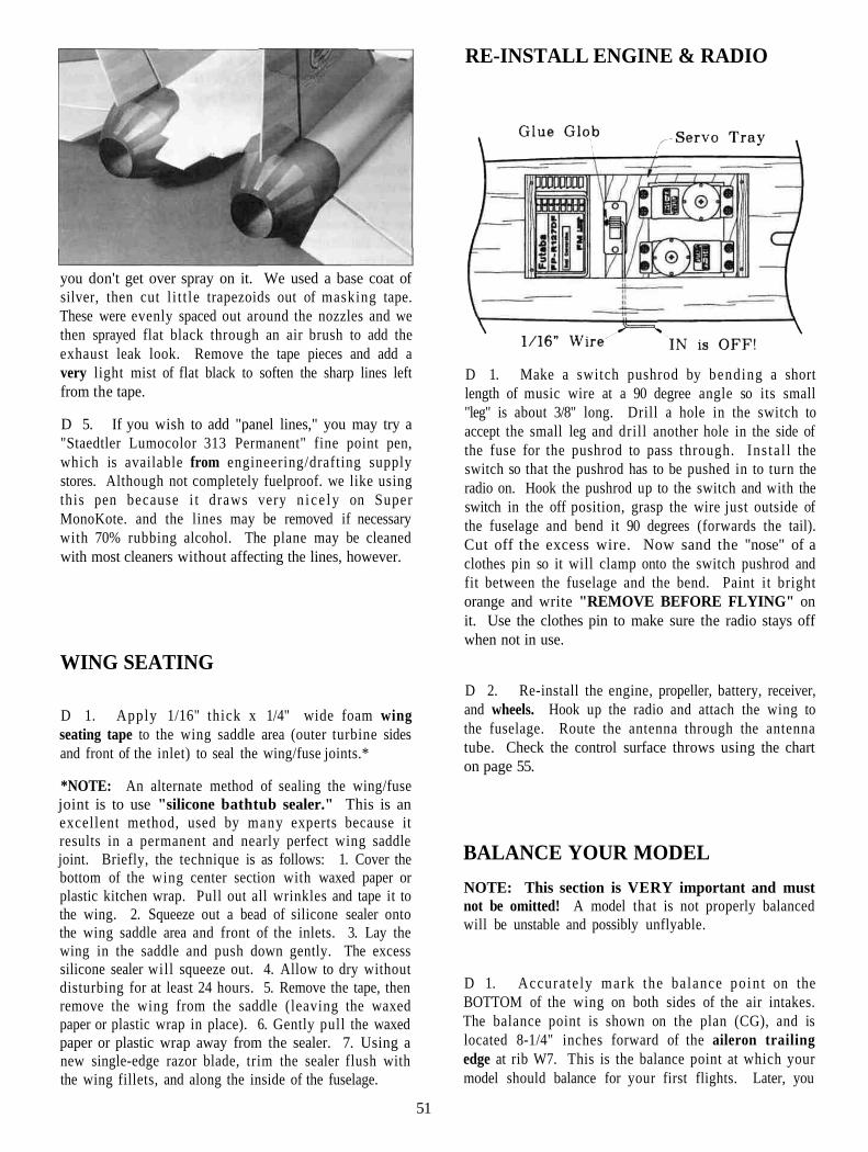
you don't get over spray on it. We used a base coat ofsilver, then cut l i t t le trapezoids out of masking tape.These were evenly spaced out around the nozzles and wethen sprayed flat black through an air brush to add theexhaust leak look. Remove the tape pieces and add avery light mist of flat black to soften the sharp lines leftfrom the tape.
D 5. If you wish to add "panel lines," you may try a"Staedtler Lumocolor 313 Permanent" fine point pen,which is available from engineering/drafting supplystores. Although not completely fuelproof. we like usingthis pen because i t draws very n i ce ly on SuperMonoKote. and the lines may be removed if necessarywith 70% rubbing alcohol. The plane may be cleanedwith most cleaners without affecting the lines, however.
RE-INSTALL ENGINE & RADIO
D 1. Make a switch pushrod by bending a shortlength of music wire at a 90 degree angle so its small"leg" is about 3/8" long. Drill a hole in the switch toaccept the small leg and drill another hole in the side ofthe fuse for the pushrod to pass through. Ins ta l l theswitch so that the pushrod has to be pushed in to turn theradio on. Hook the pushrod up to the switch and with theswitch in the off position, grasp the wire just outside ofthe fuselage and bend it 90 degrees (forwards the tail).Cut off the excess wire. Now sand the "nose" of aclothes pin so it will clamp onto the switch pushrod andfit between the fuselage and the bend. Paint it brightorange and write "REMOVE BEFORE FLYING" onit. Use the clothes pin to make sure the radio stays offwhen not in use.
WING SEATING
D 1. Apply 1/16" thick x 1/4" wide foam wingseating tape to the wing saddle area (outer turbine sidesand front of the inlet) to seal the wing/fuse joints.*
*NOTE: An alternate method of sealing the wing/fusejoint is to use "silicone bathtub sealer." This is anexcellent method, used by many experts because itresults in a permanent and nearly perfect wing saddlejoint. Briefly, the technique is as follows: 1. Cover thebottom of the wing center section with waxed paper orplastic kitchen wrap. Pull out all wrinkles and tape it tothe wing. 2. Squeeze out a bead of silicone sealer ontothe wing saddle area and front of the inlets. 3. Lay thewing in the saddle and push down gently. The excesssilicone sealer will squeeze out. 4. Allow to dry withoutdisturbing for at least 24 hours. 5. Remove the tape, thenremove the wing from the saddle (leaving the waxedpaper or plastic wrap in place). 6. Gently pull the waxedpaper or plastic wrap away from the sealer. 7. Using anew single-edge razor blade, trim the sealer flush withthe wing fillets, and along the inside of the fuselage.
D 2. Re-install the engine, propeller, battery, receiver,and wheels. Hook up the radio and attach the wing tothe fuselage. Route the antenna through the antennatube. Check the control surface throws using the charton page 55.
BALANCE YOUR MODELNOTE: This section is VERY important and mustnot be omitted! A model that is not properly balancedwill be unstable and possibly unflyable.
D 1. Accura te ly mark the balance poin t on theBOTTOM of the wing on both sides of the air intakes.The balance point is shown on the plan (CG), and islocated 8-1/4" inches forward of the aileron trailingedge at rib W7. This is the balance point at which yourmodel should balance for your first flights. Later, you
51
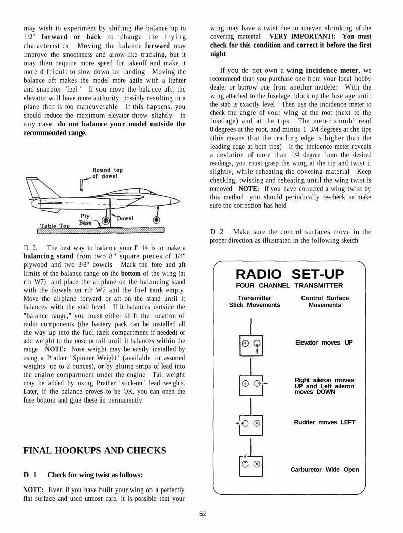
may wish to experiment by shifting the balance up to1/2" forward or back to change the f l y i n gcharacteristics Moving the balance forward mayimprove the smoothness and arrow-like tracking, but itmay then require more speed for takeoff and make itmore d i f f i cu l t to slow down for landing Moving thebalance aft makes the model more agile with a lighterand snappier "feel " If you move the balance aft, theelevator will have more authority, possibly resulting in aplane that is too maneuverable If this happens, youshould reduce the maximum elevator throw slightly Inany case do not balance your model outside therecommended range.
wing may have a twist due to uneven shrinking of thecovering material VERY IMPORTANT!: You mustcheck for this condition and correct it before the firstnight
If you do not own a wing incidence meter, werecommend that you purchase one from your local hobbydealer or borrow one from another modeler With thewing attached to the fuselage, block up the fuselage untilthe stab is exactly level Then use the incidence meter tocheck the angle of your wing at the root (next to thefuselage) and at the t ips The meter should read0 degrees at the root, and minus 1 3/4 degrees at the tips(this means that the t ra i l ing edge is higher than theleading edge at both tips) If the incidence meter revealsa deviation of more than 1/4 degree from the desiredreadings, you must grasp the wing at the tip and twist itslightly, while reheating the covering material Keepchecking, twisting and reheating unt i l the wing twist isremoved NOTE: If you have corrected a wing twist bythis method you should periodically re-check to makesure the correction has held
D 2 Make sure the control surfaces move in theproper direction as illustrated in the following sketch
D 2. The best way to balance your F 14 is to make abalancing stand from two 8 " square pieces of 1/4"plywood and two 3/8" dowels Mark the fore and aftlimits of the balance range on the bottom of the wing (atrib W7) and place the airplane on the balancing standwith the dowels on rib W7 and the fue l tank emptyMove the airplane forward or aft on the stand until itbalances with the stab level If it balances outside the"balance range," you must either shift the location ofradio components (the battery pack can be installed allthe way up into the fuel tank compartment if needed) oradd weight to the nose or tail until it balances within therange NOTE: Nose weight may be easily installed byusing a Prather "Spinner Weight" (available in assortedweights up to 2 ounces), or by gluing strips of lead intothe engine compartment under the engine Tail weightmay be added by using Prather "stick-on" lead weights.Later, if the balance proves to be OK, you can open thefuse bottom and glue these in permanently
FINAL HOOKUPS AND CHECKS
D 1 Check for wing twist as follows:
NOTE: Even if you have built your wing on a perfectlyflat surface and used utmost care, it is possible that your
TransmitterStick Movements
Control SurfaceMovements
Elevator moves UP
Right aileron movesUP and Left aileronmoves DOWN
Rudder moves LEFT
Carburetor Wide Open
RADIO SET-UPFOUR CHANNEL TRANSMITTER
52
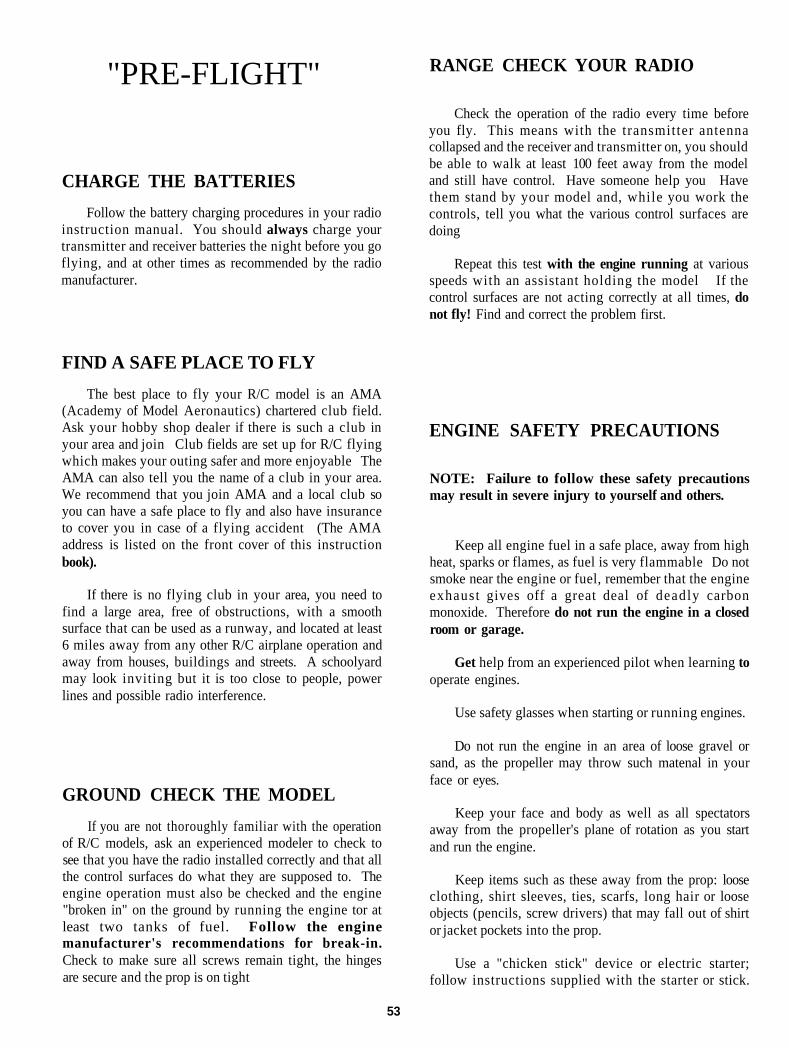
"PRE-FLIGHT" RANGE CHECK YOUR RADIO
CHARGE THE BATTERIESFollow the battery charging procedures in your radio
instruction manual. You should always charge yourtransmitter and receiver batteries the night before you goflying, and at other times as recommended by the radiomanufacturer.
Check the operation of the radio every time beforeyou fly. This means with the transmitter antennacollapsed and the receiver and transmitter on, you shouldbe able to walk at least 100 feet away from the modeland still have control. Have someone help you Havethem stand by your model and, while you work thecontrols, tell you what the various control surfaces aredoing
Repeat this test with the engine running at variousspeeds with an assistant holding the model If thecontrol surfaces are not acting correctly at all times, donot fly! Find and correct the problem first.
FIND A SAFE PLACE TO FLYThe best place to fly your R/C model is an AMA
(Academy of Model Aeronautics) chartered club field.Ask your hobby shop dealer if there is such a club inyour area and join Club fields are set up for R/C flyingwhich makes your outing safer and more enjoyable TheAMA can also tell you the name of a club in your area.We recommend that you join AMA and a local club soyou can have a safe place to fly and also have insuranceto cover you in case of a flying accident (The AMAaddress is listed on the front cover of this instructionbook).
If there is no flying club in your area, you need tofind a large area, free of obstructions, with a smoothsurface that can be used as a runway, and located at least6 miles away from any other R/C airplane operation andaway from houses, buildings and streets. A schoolyardmay look inviting but it is too close to people, powerlines and possible radio interference.
GROUND CHECK THE MODELIf you are not thoroughly familiar with the operation
of R/C models, ask an experienced modeler to check tosee that you have the radio installed correctly and that allthe control surfaces do what they are supposed to. Theengine operation must also be checked and the engine"broken in" on the ground by running the engine tor atleast two tanks of fuel. Follow the enginemanufacturer's recommendations for break-in.Check to make sure all screws remain tight, the hingesare secure and the prop is on tight
ENGINE SAFETY PRECAUTIONS
NOTE: Failure to follow these safety precautionsmay result in severe injury to yourself and others.
Keep all engine fuel in a safe place, away from highheat, sparks or flames, as fuel is very flammable Do notsmoke near the engine or fuel, remember that the engineexhaust gives off a great deal of deadly carbonmonoxide. Therefore do not run the engine in a closedroom or garage.
Get help from an experienced pilot when learning tooperate engines.
Use safety glasses when starting or running engines.
Do not run the engine in an area of loose gravel orsand, as the propeller may throw such matenal in yourface or eyes.
Keep your face and body as well as all spectatorsaway from the propeller's plane of rotation as you startand run the engine.
Keep items such as these away from the prop: looseclothing, shirt sleeves, ties, scarfs, long hair or looseobjects (pencils, screw drivers) that may fall out of shirtor jacket pockets into the prop.
Use a "chicken stick" device or electric starter;follow instructions supplied with the starter or stick.
53
Make certain the glow plug clip or connector is secure sothat it will not pop off or otherwise get into the runningpropeller
Make all engine adjustments from behind therotating propeller
The engine gets hot' Do not touch it during or afteroperation Make sure fuel lines are in good condition sofuel is not leaked onto a hot engine, causing a fire.
To stop the engine, cut off the fuel supply by closingoff the fuel line or follow the engine manufacturer'srecommendations Do not use hands, fingers or anybody part to try to stop the engine Do not throwanything into the prop of a running engine.
RADIO CONTROL
1. I will have completed a successful radio equipmentground range check before the first flight of a new orrepaired model
2. I will not fly my model aircraft in the presence ofspectators until I become a qualified flyer, unless assistedby an experienced helper
3 I will perform my initial turn after takeoff awayfrom the pit or spectator areas, and I will not thereafterfly over pit or spectator areas unless beyond my control.
4. I will operate my model using only radio controlfrequencies current ly allowed by the FederalCommunications Commission...
AMA SAFETY CODE
Read and abide by the Academy of Model AeronauticsOfficial Safety Code, a portion ot which is reprintedhere
GENERAL
1 I will not fly my model aircraft in competition or inthe presence ot spectators until it has been proven to beairworthy by having been previously, successfully flighttested.
2. I wil l not fly my model aircraft higher thanapproximately 400 feet wi th in 3 miles of an airportwithout notifying the airport operator I will give right-
aircraft Where necessary, an observer shall be utilizedto supervise flying to avoid having models fly in theproximity of full-scale aircraft
3 Where established, I will abide by the safety rulesfor the flying site I use, and I wil l not w i l l f u l l y anddeliberately fly my models in a careless, reckless and/ordangerous manner
6. I will not fly my model unless it is identified withmy name and address or AMA number, on or in themodel.
8. I will not operate models with pyrotechnics (anydevice that explodes, bums, or propels a projectile of anykind)
The Great Planes F-14 is a great flying sport scaleairplane that flies smoothly and predictably, yet is highlymaneuverable It does not have the self-recoverycharacteristics of a primary trainer, therefore, you musteither have mastered the basics of R/C flying or seek theassistance of a competent R/C pilot to help you with yourfirst flights
TAKEOFF: If you have dual rates on your transmitter,set the switches to "high rate" for takeoff, especiallywhen taking off in a cross wind Although the F-14 hasgood low speed characteristics, you should always buildup as much speed as your runway will permit beforelifting off, as this will give you a safety margin in case ofa "flame-out " When the plane has su f f i c i en t f lying
of-way and avoid flying in the proximity of full-scale speed, lift off by smoothly applying a little up elevator(don't "force" it off into a steep climb'), and climb outgradually
FLYING: We recommend that you take it easy withyour F 14 for the first several flights and gradually "getacquainted" with this fantastic ship while your enginegets fully broken-in Add and practice one maneuver at atime, learning how she behaves in each one High speedpasses and "victory rolls" are certainly most impressive,but always remember to keep safety in mind Do notexceed the recommended throws for the elevator, as thiswill only result in an increased possibility of tip stallswhen full elevator is applied Snap rolls and spins arenot as natural to this airplane as with those designed foraerobatics They may require some experimentation withthrows, balance and technique
54

CAUTION (THIS APPLIES TO ALL R/CAIRPLANES) If, while flying, you notice anyunusual sounds, such as a low-pitched "buzz," thismay be an indication of control surface "flutter"Because flutter can quickly destroy components ofyour airplane, any time you detect flutter you mustimmediately cut the throttle and land the airplane'Check all servo grommets for deterioration (thiswill indicate which surface fluttered), and makesure a l l pushrod l inkages are slop-free It i tfluttered once, it will probably flutter again undersimilar circumstances unless you can eliminate theslop or flexing in the linkages Here are somethings which can result in flutter Excessive hingegap, not mounting control horns solidly, sloppy fitof clevis pin in horn, elasticity present in flexibleplastic pushrods, side-play of pushrod in guidetube caused by tight bends, sloppy fit of Z-bend inservo arm, insufficient glue used when gluing thetorque rods into the control surfaces, excessiveflexing of aileron, caused by using too soft balsaaileron, excessive "play" or "backlash" in servogears, and insecure servo mounting
LANDING: When it's time to land, do a couple of slowfly-by's at a safe altitude to become familiar with theplane's slow flying characteristics The aerodynamicdesign of the F-14 gives it a flying quality not often foundin R/C models You will notice that as the nose comes up,the strakes start working and the fuselage starts addingsome lift As this happens, the plane will tend to balloon.This is the same characteristic that helps give the F-14 itsmaneuverability in normal flight Once the plane hasentered this "floating" stage it is still very controllable andcan be slowed down for a very gentle landing The trickto making smooth slow landings is to slow the planeearlier than normal and gently allow the plane to enter itsfloating mode Then use the throttle to regulate the glidepath. It will take a little practice, but it sure is fun tolearn.
Have a ball! But always stay in control and flyin a safe manner.
GOOD LUCK AND GREAT FLYING!
SEE THE FULL LINE OF GREAT PLANESAIRPLANES AT YOUR HOBBY DEALER WE
HOPE YOU WILL SELECT ANOTHER"GREAT PLANE" AS YOUR NEXT PROJECT
THANK YOU!
We recommend the followingCONTROL SURFACE THROWS:
NOTE: Throws measured at the widest part of thecontrol surface, wi th f u l l deflect ion of thetransmitter stick.
ELEVATOR:
RUDDER:
AILERONS:
LOW RATE1/2" bothdirections
1/2" bothdirections
1/4" bothdirections
HIGH RATE3/4" bothdirections
As much aspossible
1/2" bothdirections
NOTE: These control surface "throws" areapproximate and provide a good starting point forthe first flights with your F 14 You may wish tochange the throws sl ightly to provide thesmoothness or quickness you prefer Due to themaneuverability of this model and the high controlsurface throws that it will handle, it might be agood idea to use exponential type control surfacemovements if your radio is capable of this
55

56 GPMZ0435