instruction book - iis-servo.com
TRANSCRIPT

IB-19B007
INSTRUCTION BOOK
DELTA SERIES JULY 2003
INDUSTRIAL INDEXING SYSTEMS, Inc.
Proprietary information of Industrial Indexing Systems, Inc. furnished for customer use only. No other uses are authorized without the prior written permission of
Industrial Indexing Systems, Inc.
Revision - A Approved By:

ER-6035
ERRATA SHEET, IB-19B007 REV. A AUGUST 2006
INDUSTRIAL INDEXING SYSTEMS, Inc. 626 Fishers Run
Tel: (585) 924-9181 Victor, New York 14564 Fax: (585) 924-2169
Date Rev. ECN No. DR CHK CHK
9/3/03 0 ECN-03-392 (See Note 1) KY CD
10/28/03 A ECN-03-438, 03-446 (See Note 2) KY CM
03/25/04 B ECN-04-033 (See Note 3) KY CD
06/04/04 C ECN-04-216 (See Note 4) KY ELS/MH
11/24/04 D ECN-03-267, 03-358, 03-462 ECN-04-137, 04-198, 04-220, 04-290,
04-404 (See Note 5)
KY KY
9/23/05 E ECN-05-260 (See Note 6) KY KY
3/9/06 F ECN-06-007 (See Note 7) KY KY
8/9/06 G ECN-06-181 (See Note 8) KY KY
Notes: 1) Appendix A, page A-4, dated September 2003, supersedes Appendix A, page A-4, dated June 2003. 2) Section 4, page 4-11, dated October 2003, supersedes Section 4, page 4-11, dated July 2003.
Appendix B, page B-2, dated October 2003, supersedes Appendix B, page B-2, dated June 2003. 3) Section 6, page 6-6, dated March 2004, supersedes Section 6, page 6-6, dated July 2003. Section 10, page 10-3, dated March 2004, supersedes Section 10, page10-3, dated June 2003. 4) Section 6, page 6-6, dated June 2004, supersedes Section 6, page 6-6, dated March 2004. Appendix B, pages B-4 and B-5, dated June 2004, supersedes Appendix B, pages B-4 and B-5,
dated June 2003. C-329YYY supersedes C-320YYY. DINT-350 revision N supersedes DINT-350 revision K.
5) Appendix B, dated November 2004, supersedes Appendix B, dated June 2003. 6) Table of Contents, page vi, dated August 2005, supersedes Table of Contents, page vi, dated June
2003. Section 6, page 6-6 dated August 2005, supersedes Section 6, page 6-6, dated June 2004. Appendix A, added DBM120 series motors. Appendix B, added cables for the DBM120 series
motors. 7) Section 6, page 6-6, dated March 2006, supersedes Section 6, page 6-6, dated August 2005. 8) Appendix B, DINT-300 drawing, Revision M, supersedes Appendix B, DINT-300, Revision L.
Proprietary information of Industrial Indexing Systems, Inc. furnished for customer use only. No other uses are authorized without the prior written permission of
Industrial Indexing Systems, Inc.

INDUSTRIAL INDEXING SYSTEMS, INC. IB-19B007 DELTA S SERIES MOTORS & DRIVES USER’S GUIDE
JULY 2003 TABLE OF CONTENTS iii
TABLE OF CONTENTS
List of Illustration.................................................................................................................................................. ix Introduction.......................................................................................................................................................... xi
SECTION 1 - OVERVIEW 1.1 Identifying Delta S Packages...............................................................................................1 - 1
1.2 Identifying Delta S Drives.....................................................................................................1 - 2
1.3 Identifying Delta Motors .......................................................................................................1 - 3 SECTION 2 - DESCRIPTION 2.1 Components.........................................................................................................................2 - 2 2.1.1 Status Indicators.....................................................................................................2 - 2 2.1.2 Connectors .............................................................................................................2 - 2 SECTION 3 - SPECIFICATIONS 3.1 Driver Specifications ............................................................................................................3 - 1 3.1.1 Motor Output...........................................................................................................3 - 1 3.1.2 Power Supply .........................................................................................................3 - 2 3.1.3 Control Performance ..............................................................................................3 - 3 3.1.4 Environment............................................................................................................3 - 3 3.1.5 Sercos Interface .....................................................................................................3 - 3 3.1.6 Standard Digital Inputs/Outputs .............................................................................3 - 4 3.1.7 Optional Digital Inputs/Outputs Expansion Board .................................................3 - 4 3.1.7.1 Sourcing I/O Option “J”..........................................................................3 - 4 3.1.7.2 Sinking I/O Option “K” ...........................................................................3 - 4 3.1.8 Probe Inputs ...........................................................................................................3 - 4 3.1.9 Analog I/O Signals..................................................................................................3 - 4 3.1.10 High Speed Digital I/O Signals...............................................................................3 - 5 3.1.11 Protection................................................................................................................3 - 5
3.2 Motor Specifications.............................................................................................................3 - 5 3.2.1 General ...................................................................................................................3 - 5 3.2.2 Feedback Device....................................................................................................3 - 5 3.2.3 Other .......................................................................................................................3 - 5

IB-19B007 INDUSTRIAL INDEXING SYSTEMS, INC. USER’S GUIDE DELTA S SERIES MOTORS & DRIVES
TABLE OF CONTENTS iv AUGUST 2005
SECTION 4 - KEYPAD PROGRAMMING 4.1 Navigating the Driver’s Menu...............................................................................................4 - 2 4.1.1 Status Display Menu Loop .....................................................................................4 - 4 4.1.2 Diagnostic Display Menu Loop ..............................................................................4 - 6 4.1.3 Adjustment Parameter Menu Loop........................................................................4 - 8 4.1.4 User Parameter Menu Loop.................................................................................4 - 11 4.1.5 HP Parameter Menu Loop ...................................................................................4 - 15
4.2 Writing New Values in Read/Write Parameters ................................................................4 - 18
4.3 Navigating the Special Function Menu Loop ....................................................................4 - 18 4.3.1 Manual Jog Operation..........................................................................................4 - 19 4.3.2 Output Forcing Function.......................................................................................4 - 19 4.3.3 Auto Tuning ..........................................................................................................4 - 19 4.3.4 Link Axis Number .................................................................................................4 - 19 4.3.5 Service Data Monitor............................................................................................4 - 19
SECTION 5 - SERCOS PROGRAMMING 5.1 Sercos Setup........................................................................................................................5 - 1
5.2 Identification Numbers .........................................................................................................5 - 1 5.2.1 IDN List ...................................................................................................................5 - 1 5.2.2 IDN By Function .....................................................................................................5 - 5 5.2.3 IDN Description - Sercos Specific..........................................................................5 - 9 5.2.4 IDN Description - IIS Specific...............................................................................5 - 39 SECTION 6 - POWER WIRING 6.1 Circuit Breaker......................................................................................................................6 - 1
6.2 Contactor..............................................................................................................................6 - 1
6.3 Wire Sizes ............................................................................................................................6 - 1
6.4 Transformers........................................................................................................................6 - 2 6.5 Branch Circuit Protection for Control Voltage R0, S0.........................................................6 - 3
6.6 Wiring Practices and Grounding..........................................................................................6 - 3
6.7 Power Wiring Diagrams.......................................................................................................6 - 4

INDUSTRIAL INDEXING SYSTEMS, INC. IB-19B007 DELTA S SERIES MOTORS & DRIVES USER’S GUIDE
JULY 2003 TABLE OF CONTENTS v
SECTION 7 - I/O SIGNAL WIRING 7.1 Delta S Driver With Standard I/O Interfacing to a DINT-300 ..............................................7 - 1 7.1.1 Pin Description .......................................................................................................7 - 2
7.2 Delta S Driver With Interfacing to a DINT-300S..................................................................7 - 3 7.2.1 Pin Description .......................................................................................................7 - 4
7.3 Delta S Driver With Interfacing to a DINT-300K..................................................................7 - 5 7.3.1 Pin Description .......................................................................................................7 - 6
7.4 Delta S Optional I/O Board J (Sourcing) .............................................................................7 - 7 7.4.1 “J” Option Sourcing I/O...........................................................................................7 - 7
7.5 Delta S Optional I/O Board K (Sinking) ...............................................................................7 - 8 7.5.1 “K” Option Sinking I/O ............................................................................................7 - 8
SECTION 8 - DRIVER TUNING 8.1 Auto Tuning Sequence ........................................................................................................8 - 1 8.1.1 Special Function Menu Loop .................................................................................8 - 2 8.1.2 Auto Tuning Setup Parameters..............................................................................8 - 2 8.1.3 Initiate Auto Tuning.................................................................................................8 - 3
8.2 Manual Tuning Procedure ...................................................................................................8 - 3
8.3 Notch Filter Adjustment........................................................................................................8 - 4 SECTION 9 - REGEN RESISTOR SELECTION 9.1 Driver Regeneration Capacities...........................................................................................9 - 1
9.2 Selection of Regeneration Resistor.....................................................................................9 - 1
9.3 Standard Regeneration Resistor Packages........................................................................9 - 6
SECTION 10 - DYNAMIC BRAKES SECTION 11 - MECHANICAL BRAKES 11.1 No Mechanical Braking......................................................................................................11 - 1
11.2 Mechanical Braking............................................................................................................11 - 1
11.3 Mechanical Brake Power Supply.......................................................................................11 - 4 SECTION 12 - ALARM CODES / STATUS

IB-19B007 INDUSTRIAL INDEXING SYSTEMS, INC. USER’S GUIDE DELTA S SERIES MOTORS & DRIVES
TABLE OF CONTENTS vi AUGUST 2005
SECTION 13 - EMC INSTALLATION GUIDELINES FOR DELTA S SERIES MOTORS AND DRIVERS
13.1 Introduction to EMC Guidelines.........................................................................................13 - 1
13.2 EMC Requirements............................................................................................................13 - 1
13.3 Control Enclosure...............................................................................................................13 - 1
13.4 Enclosure Mounting Panel.................................................................................................13 - 2
13.5 Power Line Filter ................................................................................................................13 - 3
13.6 Driver Output (Motor Armature) Filter................................................................................13 - 4
13.7 Shielded Motor Cable ........................................................................................................13 - 5
13.8 Regeneration Resistor Wiring (Option) .............................................................................13 - 7
13.9 Digital Control Signals........................................................................................................13 - 8 SECTION 14 - APPLICATION NOTES 14.1 Speed Torque Curves........................................................................................................14 - 1
14.2 Pulse Input & Output..........................................................................................................14 - 2 14.2.1 Auxiliary Encoder Pulse Inputs FMA & FMB.......................................................14 - 2 14.2.2 Pulse Outputs APD, BPD & ZPD.........................................................................14 - 4 14.2.3 Setting the Resolution of the Pulse Outputs........................................................14 - 5
APPENDIX A - MOTOR/DRIVER SPECIFICATIONS A.1 Motors with Resolvers......................................................................................................... A - 1
A.2 Motors with Mechanical Brakes.......................................................................................... A - 3
A.3 Motors with Encoders ......................................................................................................... A - 4
A.4 Motor/Driver Speed Torque Curves ................................................................................... A - 5
A.5 Driver Mounting and Dimensions ..................................................................................... A - 98
A.6 Resolver Motor Dimensions ........................................................................................... A - 123
A.7 Brake Motor Dimensions ................................................................................................ A - 174
A.8 Encoder Motor Dimensions ............................................................................................ A - 199

INDUSTRIAL INDEXING SYSTEMS, INC. IB-19B007 DELTA S SERIES MOTORS & DRIVES USER’S GUIDE
JULY 2003 TABLE OF CONTENTS vii
APPENDIX B - CABLES AND ACCESSORIES
B.1 Cable Part Numbers For Motors with Resolvers ............................................................... B - 1
B.2 Cable Part Numbers For Motors with Mechanical Brakes................................................. B - 3
B.3 Cable Part Numbers For Motors with Encoders ................................................................ B - 4
B.4 Accessories......................................................................................................................... B - 5

IB-19B007 INDUSTRIAL INDEXING SYSTEMS, INC. USER’S GUIDE DELTA S SERIES MOTORS & DRIVES
TABLE OF CONTENTS viii AUGUST 2005

INDUSTRIAL INDEXING SYSTEMS, INC. IB-19B007 DELTA S SERIES MOTORS & DRIVES USER’S GUIDE
JULY 2003 LIST OF ILLUSTRATIONS ix
LIST OF ILLUSTRATIONS
SECTION 1 - OVERVIEW SECTION 2 - DESCRIPTION
Figure 2.1 Delta S Layout ........................................................................................................2 - 1
SECTION 3 - SPECIFICATIONS
Figure 3.1 Delta S Overload Protection Characteristic...........................................................3 - 6 Figure 3.2 Standard Resolver Wiring Connections for DBM-XXX/15R and DBM-500/30R and Larger......................................................................................3 - 7 Figure 3.3 Alternate Resolver Wiring Connections for DBM-XXX/15R and DBM-500/30R and Larger......................................................................................3 - 7 Figure 3.4 Standard Resolver Wiring Connections for DBM-120/30R, DBM-200/30R, DBM-400/30R, DBM-BXXX/30R, DBM-D30/30R and DBM-D50/30R.................3 - 8 Figure 3.5 Alternate Resolver Wiring Connections for DBM-120/30R, DBM-200/30R and DBM-400/30R..................................................................................................3 - 8 Figure 3.6 Standard Resolver Wiring Connections for DBM-D100/30R Through DBM-D800/30R......................................................................................................3 - 9 SECTION 4 - KEYPAD PROGRAMMING Figure 4.1 Delta S Driver Keypad and Display .......................................................................4 - 1 Figure 4.2 Main Menu Loop and Minor Loops ........................................................................4 - 3 SECTION 5 - SERCOS PROGRAMMING Figure 5.1 Velocity Polarity Parameter..................................................................................5 - 17 Figure 5.2 Position Polarity Parameter..................................................................................5 - 19 Figure 5.3 Torque Polarity Parameter ...................................................................................5 - 22 Figure 5.3 Example of Velocity Window................................................................................5 - 31 SECTION 6 - POWER WIRING Figure 6.1 Grounding Technique.............................................................................................6 - 3 Figure 6.2 DS-1.5/RB Through DS-8.5/RB Power Wiring......................................................6 - 4 Figure 6.3 DS-1.5/RA Through DS-17.5/RA Power Wiring....................................................6 - 5 Figure 6.4 DS-35/RA Through DS-115/RA Power Wiring......................................................6 - 6 SECTION 7 - I/O SIGNAL WIRING
Figure 7.1 I/O Connections to a DINT-300..............................................................................7 - 1 Figure 7.2 I/O Connections to a DINT-300S...........................................................................7 - 3 Figure 7.3 I/O Connections to a DINT-300K...........................................................................7 - 4 Figure 7.4 I/O Connections For Optional J (Sourcing) Board.................................................7 - 5 Figure 7.5 I/O Connections For Optional K (Sinking) Board ..................................................7 - 6

IB-19B007 INDUSTRIAL INDEXING SYSTEMS, INC. USER’S GUIDE DELTA S SERIES MOTORS & DRIVES
LIST OF ILLUSTRATIONS x JULY 2003
SECTION 8 - DRIVER TUNING SECTION 9 - REGEN RESISTOR SELECTION Figure 9.1 Time ........................................................................................................................9 - 2 Figure 9.2 Connection of an External Regen Resistor for Driver Sizes DS-1.5 Through DS-17.5....................................................................................................9 - 3 Figure 9.3 Connection of an External Regen Resistor for Driver Sizes DS-35 and Larger...9 - 4 Table 9.1 Energy Absorption Capabilities..............................................................................9 - 1 Table 9.2 External Resistor Specifications ............................................................................9 - 3 SECTION 10 - DYNAMIC BRAKES Figure 10.1 Dynamic Brake Connection for the DS-1.5 Through DS-17.5 Drivers ...............10 - 2 Figure 10.2 Dynamic Brake Connection for the DS-35 Through DS-115 Drivers .................10 - 3 SECTION 11 - MECHANICAL BRAKES Figure 11.1 Mechanical Brake Connection for the DS-1.5 Through DS-17.5 Drivers...........11 - 2 Figure 11.2 Mechanical Brake Connection for the DS-35 Through DS-115 Drivers.............11 - 3 SECTION 12 - ALARM CODES / STATUS SECTION 13 - EMC INSTALLATION GUIDELINES FOR DELTA S SERIES
MOTORS AND DRIVERS Figure 13.1 Enclosure Mounting Panel ...................................................................................13 - 2 Figure 13.2 Power Line Filter...................................................................................................13 - 3 Figure 13.3 Driver Output (Motor Armature) Filter ..................................................................13 - 4 Figure 13.4 Grounding Motor Armature Cable........................................................................13 - 5 Figure 13.5 Grounding Motor Armature Cable........................................................................13 - 5 Figure 13.6 Alternate Method to Ground the Motor Armature Cable .....................................13 - 6 Figure 13.7 Alternate Method to Ground the Motor Armature Cable .....................................13 - 6 Figure 13.8 SKINTOP Ground Fittings....................................................................................13 - 7 Figure 13.9 Saddle Clamp Method of Grounding ...................................................................13 - 7 SECTION 14 - APPLICATION NOTES APPENDIX A - MOTOR/DRIVER SPECIFICATIONS APPENDIX B - CABLES AND ACCESSORIES

INDUSTRIAL INDEXING SYSTEMS, Inc. IB-19B007 DELTA S SERIES MOTORS & DRIVES USER’S GUIDE
JULY 2003 INTRODUCTION xi
INTRODUCTION
Thank you for selecting Industrial Indexing Systems’ Delta Series products. You join many other companies around the world in your choice of these powerful, flexible motion control products. The Delta S Driver is based on the Delta Driver, with the addition of a SERCOS adapter, which allows the driver to interface to SERCOS InterfaceTM1 Master controllers. The small, lightweight Delta S Drivers combine the latest in all-digital electronic design, SMT circuit board construction and clever engineering to deliver high performance, advanced features and reasonable cost. Compact, high power density motors provide low rotor inertia, making them the logical choice for positioning and indexing applications. Delta S Drivers have a wide array of features, including 2 powerful embedded high speed 32-bit RISC processors, membrane keypad, high visibility 5-digit LED display and a SERCOS status display, Analog and Digital I/0, programmable limit switches, S-curve profiling, auto servo tuning, fault history log and many more. Dozens of operational parameters can be programmed, either through the front panel or using your IBM-compatible computer. And the PC software allows quick set-up for a full range of diagnostics and PC oscilloscope functions to display speed and current waveforms on your computer. High-resolution resolver feedback is standard on Delta S products. Other available choices include encoder feedback and Power Off absolute feedback.
1 SERCOS Interface is a trademark of Interest Groupe SERCOS

IB-19B007 INDUSTRIAL INDEXING SYSTEMS, Inc. USER’S GUIDE DELTA S SERIES MOTORS & DRIVES
INTRODUCTION xii JULY 2003
INDUSTRIAL INDEXING SYSTEMS, Inc. IB-19B007 DELTA S SERIES MOTORS & DRIVES USER’S GUIDE
JULY 2003 PAGE 1 - 1
SECTION 1 - OVERVIEW
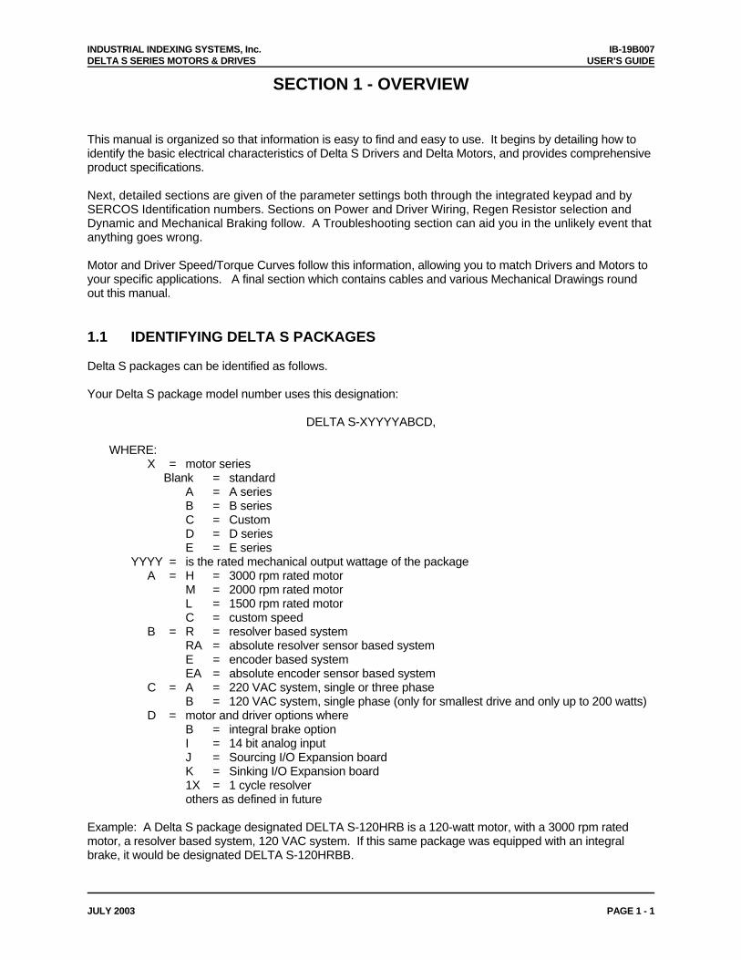
This manual is organized so that information is easy to find and easy to use. It begins by detailing how to identify the basic electrical characteristics of Delta S Drivers and Delta Motors, and provides comprehensive product specifications. Next, detailed sections are given of the parameter settings both through the integrated keypad and by SERCOS Identification numbers. Sections on Power and Driver Wiring, Regen Resistor selection and Dynamic and Mechanical Braking follow. A Troubleshooting section can aid you in the unlikely event that anything goes wrong. Motor and Driver Speed/Torque Curves follow this information, allowing you to match Drivers and Motors to your specific applications. A final section which contains cables and various Mechanical Drawings round out this manual. 1.1 IDENTIFYING DELTA S PACKAGES Delta S packages can be identified as follows. Your Delta S package model number uses this designation:
DELTA S-XYYYYABCD, WHERE: X = motor series Blank = standard A = A series B = B series C = Custom D = D series E = E series YYYY = is the rated mechanical output wattage of the package A = H = 3000 rpm rated motor M = 2000 rpm rated motor L = 1500 rpm rated motor C = custom speed B = R = resolver based system RA = absolute resolver sensor based system E = encoder based system EA = absolute encoder sensor based system C = A = 220 VAC system, single or three phase B = 120 VAC system, single phase (only for smallest drive and only up to 200 watts) D = motor and driver options where B = integral brake option I = 14 bit analog input J = Sourcing I/O Expansion board K = Sinking I/O Expansion board 1X = 1 cycle resolver others as defined in future Example: A Delta S package designated DELTA S-120HRB is a 120-watt motor, with a 3000 rpm rated motor, a resolver based system, 120 VAC system. If this same package was equipped with an integral brake, it would be designated DELTA S-120HRBB.

IB-19B007 INDUSTRIAL INDEXING SYSTEMS, Inc. USER’S GUIDE DELTA S SERIES MOTORS & DRIVES
PAGE 1 - 2 JULY 2003
1.2 IDENTIFYING DELTA S DRIVES Delta S Drivers can be identified as follows. This information is on the Driver label: Your Delta S Driver model number uses this designation:
DS-CURRENT/ZYX, WHERE: CURRENT = Peak Driver Current in amps (rms) Z = feedback method: R = resolver feedback E = encoder feedback RA = absolute resolver feedback EA = absolute encoder feedback Y = input voltage: A = 220 VAC input (single or three phase) B = 115 VAC input (single phase) - only available up to 200 watts X = option: I = 14 bit analog input A & D converter J = Sourcing I/O Expansion board K = Sinking I/O Expansion board Example: A Delta S Driver designated DS-8.5/RB has a peak current rating of 8.5 A rms, resolver feedback, and 115 VAC 1 input voltage.

INDUSTRIAL INDEXING SYSTEMS, Inc. IB-19B007 DELTA S SERIES MOTORS & DRIVES USER’S GUIDE
JULY 2003 PAGE 1 - 3
1.3 IDENTIFYING DELTA MOTORS Delta Motors can be identified as follows. This information is on the Motor label: Your Delta Motor model number uses this designation:
DBM-SERIES WATTAGE/SPEED YZ, WHERE: SERIES = Motor series Blank = standard A = A series B = B series C = Custom D = D series E = E series WATTAGE = Rated Motor Power in watts SPEED = Rated Motor Speed in hundreds of RPMs Y = feedback method: R = resolver feedback E = encoder feedback RA = absolute resolver feedback EA = absolute encoder feedback Z = B for a motor with an integral brake T for windings with “Tropical” fungus protection W for washdown sealing 1X = 1 cycle resolver Example: A Delta Motor designated DBM-120/30R is a 120-watt motor with a 3000 rpm rated speed and resolver feedback. If this same motor was equipped with an integral brake, it would be designated DBM-120/30RB. If the same motor was equipped with “Tropical” fungus protection, it would be designated DBM-120/30RT and with a brake, it would be designated DBM-120/30RBT.

IB-19B007 INDUSTRIAL INDEXING SYSTEMS, Inc. USER’S GUIDE DELTA S SERIES MOTORS & DRIVES
PAGE 1 - 4 JULY 2003

INDUSTRIAL INDEXING SYSTEMS, Inc. IB-19B007 DELTA S SERIES MOTORS & DRIVES USER’S GUIDE
JULY 2003 PAGE 2 - 1
SECTION 2 - DESCRIPTION
The Delta S is a SERCOS Interface compatible servo drive. When interfaced to a SERCOS Master controller, access can be made to a wide variety of hardware features along with the SERCOS standard motion configurations. The external connections that exist on the Delta S are shown in Figure 2.1, and consist of 2 RS-232 ports, 8 digital inputs and 8 digital outputs standard, 2 analog inputs, SERCOS Fiber Optic Transmitter and Receiver, as well as motor, resolver, and power connections. The Delta drive also has an analog monitor output that is capable of representing either speed or torque as a function of voltage relative to +/- 3 vdc.
Figure 2.1 - Delta S Layout

IB-19B007 INDUSTRIAL INDEXING SYSTEMS, Inc. USER’S GUIDE DELTA S SERIES MOTORS & DRIVES
PAGE 2 - 2 JULY 2003
2.1 COMPONENTS 2.1.1 STATUS INDICATORS 1. Drive Status Display - This is a 5-digit seven segment display which indicates the current status
of the Delta driver. A fault on the drive would be represented by AL - ## which indicates an alarm with an associated two digit number. These alarm codes and their descriptions can be found in Section 12 - Alarm & Status Codes.
2. SERCOS Status Display- This 4 LED array provides status information on the current state of the
SERCOS Interface. For further information on this display, see Section 12 - Alarm & Status Codes in this manual.
2.1.2 CONNECTORS 1. Com 1 - This 6-pin RJ-11 connector is an RS-232 serial communication port. This port is utilized
to update the firmware in the SERCOS Adapter. 2. Com 2 - This 14-pin connector is an RS-232 serial communication port. With PC software this
port can be used to download, upload, or change drive parameters, drive diagnostics, and PC oscilloscope functions.
3. I/O Interface- This connector provides access to the onboard I/O, including 8 optically isolated
inputs, 8 optically isolated outputs, 2 analog inputs, auxiliary encoder pulse input and pulse output. IIS offers two cable options to this connector; there is the C-719YYY cable with ferruled ends or the C-716006 cable that terminates at the DINT-300, which provides terminal blocks for I/O wiring.
4. SERCOS Transmitter/Receiver- These fiber optic ports allow the drive to be interfaced to a
SERCOS Master Controller.
5. Probes- High Speed Optically Isolate inputs that can be configured to trap the motor feedback position.
6. Resolver Cable Connector - This is a 20-pin mini D connector used for resolver feedback from
the motor to the drive.
7. Motor/Power wiring terminals - These are terminal blocks used to wire the incoming AC line voltage as well as the motor cable.
8. Monitor Output - This is a connector that provides access to an analog output signal. The signal
is can be defined as a conversion of torque or speed.

INDUSTRIAL INDEXING SYSTEMS, Inc. IB-19B007 DELTA S SERIES MOTORS & DRIVES USER’S GUIDE
JULY 2003 PAGE 3 - 1
SECTION 3 - SPECIFICATIONS
3.1 DRIVER SPECIFICATIONS
Delta S Driver DS-1.5/RB DS-1.5/RA DS-4.25/RB DS-4.25/RA Weight 3.3 lb
1.5 kg 3.3 lb 1.5 kg
3.3 lb 1.5 kg
3.3 lb 1.5 kg
Delta S Driver
DS-
8.5/RB DS-
8.5/RA DS-
17.5/RA DS-
35/RA DS-
50/RA DS-
70/RA DS-
115/RA Weight 3.3 lb
1.5 kg 3.3 lb 1.5 kg
5.5 lb 2.5 kg
10 lb 4.5 kg
10 lb 4.5 kg
24 lb 11 kg
35 lb 16 kg
3.1.1 MOTOR OUTPUT
Delta S Driver DS-1.5/RB DS-1.5/RA DS-4.25/RB DS-4.25/RA Motor Output PWM, 3 Phase, sine wave Continuous Output Current
1.0 A rms
1.0 A rms
2.8 A rms
2.8 A rms
Max. Output Current See Figure 3.1
1.5 A rms
1.5 A rms
4.25 A rms
4.25 A rms
Motor Ripple Frequency
20 kHz 20 kHz 20 kHz 20 kHz
Delta S Driver
DS-
8.5/RB DS-
8.5/RA DS-
17.5/RA DS-
35/RA DS-
50/RA DS-
70/RA DS-
115/RA Motor Output PWM, 3 Phase, sine wave Continuous Output Current
2.1 A rms
3.4 A rms
5.7 A rms
14.1 A rms
18.4 A rms
28.3 A rms
56.6 A rms
Max. Output Current See Figure 3.1
8.5 A rms
8.5 A rms
17.5 A rms
35.0 A rms
50.0 A rms
70.0 A rms
115.0 A rms
Motor Ripple Frequency
20 kHz 20 kHz 20 kHz 20 kHz 20 kHz 10 kHz 10 kHz

IB-19B007 INDUSTRIAL INDEXING SYSTEMS, Inc. USER’S GUIDE DELTA S SERIES MOTORS & DRIVES
PAGE 3 - 2 JULY 2003
3.1.2 POWER SUPPLY Delta S Driver DS-1.5/RB DS-1.5/RA DS-4.25/RB DS-4.25/RA Main Bus Power Supply Voltage
1 Phase, Nominal: 110 VAC, Max Range: 85-126 VAC, 50/60 Hz
1 Phase, Nominal: 220 VAC, Max Range: 170-264 VAC, 50/60 Hz
1 Phase, Nominal: 110 VAC, Max Range: 85-126 VAC, 50/60 Hz
1 Phase, Nominal: 220 VAC, Max Range: 170-264 VAC, 50/60 Hz
Main Supply Capacity
350 VA 350 VA 350 VA 350 VA
Control Voltage Powered by main circuit supply Control Capacity
Powered by main circuit supply
Main Circuit Heat Loss
17 W 17 W 17 W 17 W
Control Circuit Heat Loss
23 W 23 W 23 W 23 W
Regeneration Absorption Capacity
13 W + 17 J 13 W + 17 J 13 W + 17 J 13 W + 17 J
Delta S Driver
DS-
8.5/RB DS-
8.5/RA DS-
17.5/RA DS-
35/RA DS-
50/RA DS-
70/RA DS-
115/RA Main Bus Power Supply Voltage
1 Phase, Nominal: 110 VAC, Max Range: 85-126 50/60 Hz
1 Phase, Nominal: 220 VAC, Max Range: 170-264 VAC, 50/60 Hz
3 Phase, Nominal: 220 VAC, Max Range: 170-264 VAC, 50/60 Hz
Main Supply Capacity
570 VA 1.2 KVA 2.5 KVA 5.3 KVA 6.7 KVA 13 KVA 25 KVA
Control Voltage Powered by main circuit supply Single phase, 170-264 VAC, 50/60 Hz Control Capacity
Powered by main circuit supply 70 VA 80 VA 110 VA
Main Circuit Heat Loss
20 W 27 W 47 W 110 W 130 W 250 W 400 W
Control Circuit Heat Loss
23 W 23 W 23 W 26 W 26 W 30 W 60 W
Regeneration Absorption Capacity
17 W + 17 J
24 W + 17 J
37 W + 22 J
160 W + 38 J
180 W + 54 J
300 W + 94 J
480 W + 188 J

INDUSTRIAL INDEXING SYSTEMS, Inc. IB-19B007 DELTA S SERIES MOTORS & DRIVES USER’S GUIDE
JULY 2003 PAGE 3 - 3
3.1.3 CONTROL PERFORMANCE Feedback Resolver Feedback Resolution
12000 bits/rev * number of resolver cycles ie. 2X resolver = 2*12000 bits/rev = 24000 bits/rev. See motor drawings in Appendix A.6 for resolver type.
Feedback Accuracy
18 arc minutes spread for motors with 95 mm mounting face or smaller ±20 arc minutes for B series motors 8 arc minute spread for all other motors
Speed Regulation
Load (0%-100%): 0.02% Power (85-126 VAC or 170-264 VAC): 0.02% Temperature (0-55C/32-131F): 0.2%
Torque Regulation
Power (85-126 VAC or 170-264 VAC): 2% Temperature (0-55C/32-131F): 2%
Feedback Encoder Feedback Resolution
See motor drawings in Appendix A.8 for encoder type.
Feedback Accuracy
Less than 2 arc minutes.
Speed Regulation
Load (0%-100%): 0.02% Power (85-126 VAC or 170-264 VAC): 0.02% Temperature (0-55C/32-131F): 0.2%
Torque Regulation
Power (85-126 VAC or 170-264 VAC): 2% Temperature (0-55C/32-131F): 2%
3.1.4 ENVIRONMENT Storage Temperature
-10 to 70C/14-158F
Operating Temperature
0 to 55C/32-131F
Humidity 35 to 90% Relative Humidity, non-condensing Shock and Vibration
1 G or less
Operating Conditions
Free of dust, liquids, metallic particles and corrosive gases. Use in a pollution degree 2 environment.
Drive Enclosure
The drive is rated as “open type equipment” by Underwriters Laboratories, Inc.
3.1.5 SERCOS INTERFACE Interface Version
V01.02
Topology Multi drop fiber optic ring Transmission Rates
2, 4, 8 and 16 MB/second

IB-19B007 INDUSTRIAL INDEXING SYSTEMS, Inc. USER’S GUIDE DELTA S SERIES MOTORS & DRIVES
PAGE 3 - 4 JULY 2003
3.1.6 STANDARD DIGITAL INPUTS/OUTPUTS
Control Input 24 VDC 8 ma: common to +24V, optically isolated Standard Sinking I/O Control Output 24 VDC 40 ma: common to 24G, optically isolated Control Input 24 VDC 6 ma: common to +24V, optically isolated Optional Sinking I/O
DINT-300K Control Output 24 VDC 400 ma: common to 24G, optically isolated Control Input 24 VDC 6 ma: common to 24G, optically isolated Optional Sourcing I/O
DINT-300S Control Output 24 VDC 400 ma: common to +24V, optically isolated Internal Power Supply
24 VDC 15% 100 ma maximum, ground isolated
External Power Supply
24 VDC 15%
3.1.7 OPTIONAL DIGITAL INPUTS/OUTPUTS EXPANSION BOARD 3.1.7.1 SOURCING I/O OPTION “J”
Input 24 VDC 5 ma: common to 24G, optically isolated Output 24 VDC 500 ma common to +24V, optically isolated Internal Power Supply
24 VDC 15%
3.1.7.2 SINKING I/O OPTION “K” Input 24 VDC 5 ma: common to +24V, optically isolated Output 24 VDC 500 ma common to 24G, optically isolated Internal Power Supply
24 VDC 15%
3.1.8 PROBE INPUTS Probe Input 1 Probe Input 2
24 VDC 5 ma
3.1.9 ANALOG I/O SIGNALS Analog Input 1 and Analog Input 2
Maximum Input Voltage: 10 VDC Input Impedance: 18 k A/D resolution: 1/1024 at 10V (10 bit Standard, 14 bit Optional) Scaleable with setup parameter
Monitor Output Maximum Voltage Swing: 3 VDC at 1 ma Output Impedance: 330 Accuracy: 8% Monitor Scaling Speed: 3V equals motor rated speed Torque: 3V equals motor peak torque C-722006 Monitor Cable Available
Monitor Test Point
Analog Ground

INDUSTRIAL INDEXING SYSTEMS, Inc. IB-19B007 DELTA S SERIES MOTORS & DRIVES USER’S GUIDE
JULY 2003 PAGE 3 - 5
3.1.10 HIGH SPEED DIGITAL I/O SIGNALS
Auxiliary Encoder Pulse Input FMA and /FMA FMB and /FMB
On voltage: 5 VDC 5% at 17 ma maximum Off voltage: 1 VDC 5% less than 1 ma 200 KHz maximum frequency in pulse-pulse or pulse-direction modes 50 KHz in AB quadrature mode Optically isolated
Pulse Output APD and /APD BPD and /BPD ZPD and /ZPD
RS422 output: AM26LS31 or equiv. 400 kHz maximum frequency
3.1.11 PROTECTION
Fault Checks Under Voltage, Over Voltage, Motor Short, Output Short, Feedback Loss, Regeneration Resistor Over Temperature and Malfunction, Driver Over Temperature, Motor rms Torque (motor overheat) Driver Rated Current, Over Speed, Motor Stall, Dynamic or Mechanical Brake Failure, Following Error, Internal Watchdog Timer, Processor Diagnostics
Output Short Circuit Protection
The drives are suitable for use on a circuit capable of delivering not more than 5000 rms symmetrical amperes, 240 volts maximum when protected by a circuit breaker having an interrupting rating not less than 5000 rms symmetrical amperes, 240 volts maximum.
3.2 MOTOR SPECIFICATIONS
3.2.1 GENERAL
Duty Continuous at rated speed and rated torque Type Permanent magnet synchronous Insulation Class F Sealing See motor drawings in Appendix A.6, A.7 & A.8 Storage Temperature -10 to +70ºC/14 to 158ºF Ambient Operating Temperature -10 to +40ºC/14 to 104ºF Shock and Vibration 2 G’s Mounting Motor can be mounted in any position 3.2.2 FEEDBACK DEVICE
Type: Resolver Resolver control transformer See motor drawings in Appendix A.6 & A.7
Type: Encoder ABZ plus UVW 5V line driver See motor drawings in Appendix A.8
3.2.3 OTHER
Weight Shaft Loading Brake Specifications Dimensions
See motor drawings in Appendix A.6, A.7 & A.8
Torque Ratings Speed Torque Curves
See specifications in Appendix A.4

IB-19B007 INDUSTRIAL INDEXING SYSTEMS, Inc. USER’S GUIDE DELTA S SERIES MOTORS & DRIVES
PAGE 3 - 6 JULY 2003
Figure 3.1 - Delta S Overload Protection Characteristic

INDUSTRIAL INDEXING SYSTEMS, Inc. IB-19B007 DELTA S SERIES MOTORS & DRIVES USER’S GUIDE
JULY 2003 PAGE 3 - 7
Figure 3.2 - Standard Resolver Wiring Connections for DBM-XXX/15R and DBM-500/30R and Larger
Figure 3.3 - Alternate Resolver Wiring Connections for DBM-XXX/15R and DBM-500/30R and Larger

IB-19B007 INDUSTRIAL INDEXING SYSTEMS, Inc. USER’S GUIDE DELTA S SERIES MOTORS & DRIVES
PAGE 3 - 8 JULY 2003
Figure 3.4 - Standard Resolver Wiring Connections for DBM-120/30R, DBM-200/30R, DBM-400/30R, DBM-BXXX/30R, DBM-D30/30R and DBM-D50/30R
Figure 3.5 - Alternate Resolver Wiring Connections for DBM-120/30R, DBM-200/30R and DBM-400/30R

INDUSTRIAL INDEXING SYSTEMS, Inc. IB-19B007 DELTA S SERIES MOTORS & DRIVES USER’S GUIDE
JULY 2003 PAGE 3 - 9
Figure 3.6 - Standard Resolver Wiring Connections for DBM-D100/30R Through DBM-D800/30R

IB-19B007 INDUSTRIAL INDEXING SYSTEMS, Inc. USER’S GUIDE DELTA S SERIES MOTORS & DRIVES
PAGE 3 - 10 JULY 2003

INDUSTRIAL INDEXING SYSTEMS, Inc. IB-19B007 DELTA S SERIES MOTORS & DRIVES USER’S GUIDE
OCTOBER 2003 PAGE 4 - 1
SECTION 4 - KEYPAD PROGRAMMING
The Delta S Driver is a fully digital driver that has a rich set of motion control building blocks that are configurable using the driver’s software. A built in keypad and display can be used to set internal parameters that configure the driver’s software. An easy to use menu scheme allows the user to: Activate optional features Monitor key parameters and alarms Adjust driver parameters Manual or automatic tuning of the motor and driver Manual testing of driver operation The drivers’ keypad and display are shown in Figure 4.1. The functions are as follows: LED DISPLAY is a 5-digit unit that displays coded messages, alarms and parameter values.
Messages are displayed in coded bit patterns, hexadecimal, decimal and coded letters.
UP-ARROW is used to navigate around the minor menu loops, to increase the value of a parameter and in combination with other keys for special functions.
DOWN-ARROW is used to navigate around the minor menu loops, to decrease the value of a parameter and in combination with other keys for special functions.
SELECT is used to identify which digit of the display is selected for modification (flashing). This
key is also used in combination with the CONFIRM key to prepare a parameter for modification.
MODE is used to navigate the main menu loop and to return to the main menu loop from the minor loops.
CONFIRM is used to confirm a parameter value and to set into non-volatile memory and to reset
alarms. This key is also used in combination with the SELECT key to prepare a parameter for modification.
FLASHING DECIMAL POINT indicates that an alarm is active.
Figure 4.1 - Delta S Driver Keypad and Display
r
SEL
MODE
MON

IB-19B007 INDUSTRIAL INDEXING SYSTEMS, Inc. USER’S GUIDE DELTA S SERIES MOTORS & DRIVES
PAGE 4 - 2 FEBRUARY 2004
4.1 NAVIGATING THE DRIVER’S MENU The menu structure for programming the driver consists of a main menu loop with several minor menu loops and the Special Menu. The main menu loop and partial sections of the minor loops are shown in Figure 4.2. The major loop is shown vertically on the left side of the diagram. There are four major items on the main menu loop. Each of these items are the starting point for minor menu loops. STATUS DISPLAY minor menu loop contains drive and motor status displays such as motor speed,
motor position, following error, etc. DIAGNOSTIC DISPLAY minor menu loop provides diagnostic information such as I/O status, alarms
and alarm history. ADJUST PARAMETER minor menu loop contains parameters that are typically adjusted by the user.
Parameters include speed scaling, servo tuning values and load inertia setting. USER PARAMETER minor menu loop contains basic configuration parameters that are usually set
once per application such as control mode, motor type, electronic gear ratio and analog polarity. HP PARAMETER is a sub-menu loop from the USER PARAMETER minor menu. This sub-menu
loop also contains configuration parameters that are less frequently used or modified.
The key is used to move around the main menu loop. Once the main menu is positioned on the first
parameter of a minor loop the and keys are used to move around the minor menu loop. When in
the minor menu loop the and or the and keys move through the parameters in jumps of
10 rather then 1. The mode key can be used to move from anywhere in the minor menu back to the main menu loop. The HP parameter sub-menu is entered by putting the main menu loop on UP-02 and pressing and
holding the key then pressing both the and keys. Once in the HP sub-menu the and
keys are used to move around the sub-menu. The must be pressed twice quickly to move from the HP sub-menu back to the UP minor menu. The Special Function Menu is used for Auto Tuning, manual jogging of the motor and forcing outputs. Section 4.3 describes the Special Function Menu.

INDUSTRIAL INDEXING SYSTEMS, Inc. IB-19B007 DELTA S SERIES MOTORS & DRIVES USER’S GUIDE
OCTOBER 2003 PAGE 4 - 3
4.1 NAVIGATING THE DRIVER’S MENU (cont’d)
Figure 4.2 - Main Menu Loop and Minor Loops
A’---- A ---- r ---- STATUS DISPLAY LOOP
c.in --- c.ou --- c ---- DIAGNOSTIC DISPLAY LOOP
AJ0 VALUE AJ1
AJ0 ADJUST PARAMETER LOOP
HP-33 VALUE HP-34
TWICE
TOGETHER
THEN
HP-33 HP PARAMETER LOOP
UP-02 VALUE UP-03
UP-02 USER PARAMETER LOOP

IB-19B007 INDUSTRIAL INDEXING SYSTEMS, Inc. USER’S GUIDE DELTA S SERIES MOTORS & DRIVES
PAGE 4 - 4 FEBRUARY 2004
4.1.1 STATUS DISPLAY MENU LOOP The Status Display Menu Loop provides a real time display of motor and driver status. The display format uses the left most digits for a coded message of the item to be displayed and the right most digits are the value. The coded item on the left will flash indicating negative (-) value. The sign convention is (+) is CCW and (-) is CW. Some of the display values, such as A’ & A, are too large for a single display so they are broken into two sections and are displayed on two successive menu displays. The prime (‘) symbol indicates the upper four (4) digits or most significant section and the non-prime symbol indicates lower four (4) digits. For example, if successive displays reads [A’ 1466] and [A 6789], the ACTUAL POSITION is 14666789. Parameters can only be read in the Status Display Menu. The driver is set to the (r) Motor Speed at power application. Any alarm will overwrite the display. The Status Display Menu is organized as follows:
P’ & P AUXILIARY ENCODER POSITION
F’ & F SCALED MOTOR
SPEED
cF ANALOG IN1
VOLTAGE
cc ANALOG IN2
VOLTAGE
L MOTOR PEAK
CURRENT
bL % MOTOR TORQUE
oL % MOTOR
TEMPERATURE
d MARKER POSITION
rL % RATED
ABSORPTION
A’& A ACTUAL
POSITION
r MOTOR SPEED
C’ & C COMMAND POSITION
E’ & E FOLLOWING
ERROR

INDUSTRIAL INDEXING SYSTEMS, Inc. IB-19B007 DELTA S SERIES MOTORS & DRIVES USER’S GUIDE
OCTOBER 2003 PAGE 4 - 5
4.1.1 STATUS DISPLAY MENU LOOP (cont’d) Status Display Descriptions: DISPLAY ITEM SYMBOL RANGE &
UNITS CONTENTS
Motor rpm r 4000 RPM Displays the speed of motor. Actual Position A’ A 9999999
Bits Displays the actual position of the motor. With resolver feedback, the 0.0 position at power up is referenced to the nearest resolver 0.0. The Delta motors have a 2X resolver, and have two 0.0 points or markers per motor shaft rotation. When the count exceeds display range, 9999999 appears.
Command Position
C’ C 9999999 Bits
Displays the command position of the driver (scaled by UP-05/UP-04 similar to A’ A above). When the count exceeds display range, 9999999 appears.
Following Error E’ E 9999999 Bits
Displays the difference between command position and actual position. Used in position control mode only.
Auxiliary Encoder Pulse Position
P’ P +32767 32768 Pulses
Displays the auxiliary encoder position register. This counter is a signed 16-bit counter with a range of +32767 to -32768. Counter rolls over when it reaches the maximum count (ring counter).
Scaled Motor Speed
F’ F 9999999 RPM
Displays the speed of the motor scaled by HP-41/HP-42. This used typically used to display “machine speed” if the speed exceeds display range, 9999999 appears.
Analog In1 Voltage
cF 10.0 V Displays the input voltage for Analog Input 1.
Analog In2 Voltage
cc 10.0 V Displays the input voltage for Analog Input 2
Motor Peak Current
L 160.0 A (peak)
Displays the output current to motor. “A (peak)” shows the peak value of AC current.
% Motor Torque
bL 0255% Displays the load ratio (output torque/rated torque) * 100%. The time constant for calculating this ratio is set by HP-33.
% Motor Temperature
oL 0110% Displays calculated motor temperature as a % of the maximum rating. The electronic motor thermal limit alarm activates at 110% (AL-17). oL initializes to 90% at power on.
Marker Position d 0359.9 deg Displays the motor shaft angle from the motor marker ZPD position. The driver has N marker ZPD positions depending on the resolver/encoder installed in the motor. (i.e. a motor with a 2X resolver has 2 ZPD positions per motor revolution, see motor drawings in Appendix A.6, A.7 & A.8). If the motor has 3X resolver and 3 ZPD positions, this display will go from 0.0 to 359.9 degrees 3 times per motor rotation.
% Rated Absorption
rL 0100% For DS-1.5, DS-4.25, DS-8.5 and DS-17.5 the display is (motor absorption torque/motor rated torque) * 100%. For DS-35 and up the display is % rating of the regeneration resistor capacity (UL-31).

IB-19B007 INDUSTRIAL INDEXING SYSTEMS, Inc. USER’S GUIDE DELTA S SERIES MOTORS & DRIVES
PAGE 4 - 6 FEBRUARY 2004
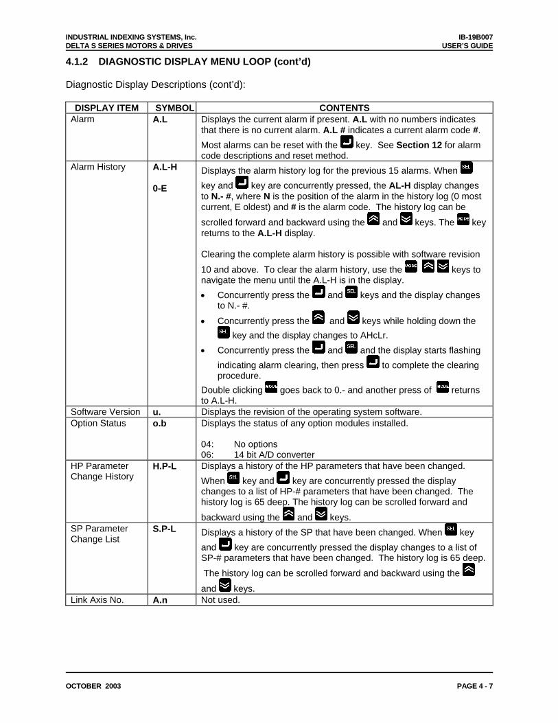
4.1.2 DIAGNOSTIC DISPLAY MENU LOOP The Diagnostic Display Menu Loop provides a real time display of I/O points, alarms, alarm history and driver configurations. The display format uses the left most digits for a coded message of the item to be displayed and the right most digits are the value. Some of the display values, such as A.L-H ALARM HISTORY require additional keystrokes to view the complete status. The additional keystrokes are described in the individual display descriptions. Parameters can only be read in the Diagnostic Display Menu, with the exception that the ALARM HISTORY can be cleared. The Diagnostic Display Menu Loop is organized as follows: Diagnostic Display Descriptions:
DISPLAY ITEM SYMBOL CONTENTS General purpose I/O
c. Displays the current I/O status using the vertical segment bars in the display. The top half of the segment bar are inputs and the bottom half are outputs. The right most vertical bar is IN1 (top half) and OUT1 (bottom half). The vertical bar just to the right of the c. is IN8 (top half) and OUT8 (bottom half). When the bar is illuminated the I/O point is ON. The I/O point can be inverted using HP-44 & HP-45. See the individual signal level I/O diagrams in Section 7. NOTE: The IN9-IN16 and OUT9-OUT16 status cannot be viewed on display.
General Purpose Input
c.in Not used.
General Purpose Output
c.out Not used.
IN1
OUT1
IN8
OUT8
c. GENERAL
PURPOSE I/O
c.in EXPANDED
INPUTS
c.ou EXPANDED OUTPUTS
A.L PRESENT ALARM
A.L-H ALARM
HISTORY
u. SOFTWARE
VERSION
o.b OPTION STATUS
H.P-L PARAMETER
LIST
S.P-L PARAMETER
LIST
A.n LINK AXIS ADDRESS
INDUSTRIAL INDEXING SYSTEMS, Inc. IB-19B007 DELTA S SERIES MOTORS & DRIVES USER’S GUIDE
OCTOBER 2003 PAGE 4 - 7
4.1.2 DIAGNOSTIC DISPLAY MENU LOOP (cont’d) Diagnostic Display Descriptions (cont’d):
DISPLAY ITEM SYMBOL CONTENTS Alarm A.L Displays the current alarm if present. A.L with no numbers indicates
that there is no current alarm. A.L # indicates a current alarm code #.
Most alarms can be reset with the key. See Section 12 for alarm code descriptions and reset method.
Alarm History A.L-H 0-E
Displays the alarm history log for the previous 15 alarms. When
key and key are concurrently pressed, the AL-H display changes to N.- #, where N is the position of the alarm in the history log (0 most current, E oldest) and # is the alarm code. The history log can be
scrolled forward and backward using the and keys. The key returns to the A.L-H display. Clearing the complete alarm history is possible with software revision
10 and above. To clear the alarm history, use the keys to navigate the menu until the A.L-H is in the display.
Concurrently press the and keys and the display changes to N.- #.
Concurrently press the and keys while holding down the
key and the display changes to AHcLr.
Concurrently press the and and the display starts flashing
indicating alarm clearing, then press to complete the clearing procedure.
Double clicking goes back to 0.- and another press of returns to A.L-H.
Software Version u. Displays the revision of the operating system software. Option Status o.b Displays the status of any option modules installed.
04: No options 06: 14 bit A/D converter
HP Parameter Change History
H.P-L Displays a history of the HP parameters that have been changed.
When key and key are concurrently pressed the display changes to a list of HP-# parameters that have been changed. The history log is 65 deep. The history log can be scrolled forward and
backward using the and keys. SP Parameter Change List
S.P-L Displays a history of the SP that have been changed. When key
and key are concurrently pressed the display changes to a list of SP-# parameters that have been changed. The history log is 65 deep.
The history log can be scrolled forward and backward using the
and keys. Link Axis No. A.n Not used.

IB-19B007 INDUSTRIAL INDEXING SYSTEMS, Inc. USER’S GUIDE DELTA S SERIES MOTORS & DRIVES
PAGE 4 - 8 FEBRUARY 2004
4.1.3 ADJUSTMENT PARAMETER MENU LOOP The Adjustment Parameter Menu Loop provides access to setup and tuning parameters that are commonly used. Each parameter is displayed in two successive displays. The coded parameter name
appears on the first display and the parameter value appears on the second display. The key will
always move from the parameter-coded name to the parameter value. The key will always move from the parameter value to the coded parameter name. If the parameter value is negative, a (-) sign appears in the left most digit of the display. Parameters can be read or written in the Adjust Parameter Menu Loop. The procedure to write into a parameter is found in Section 4.2. The Adjustment Parameter Menu Loop is organized as follows:
AJ0 - 0.03
AJ1 ANALOG IN1
VOLTAGE SCALE
AJ0 ANALOG IN1
VOLTAGE ZERO
AJ2 LOAD INERTIA
RATIO
AJ3 HIGH FREQ. RESPONSE
AJ4 POSITION LOOP
GAIN
AJ5 ANALOG IN2
VOLTAGE ZERO
AJ6 ANALOG IN2
VOLTAGE SCALE
AJ7 “0” SPEED GAIN
REDUCTION
AJ8 FEED FORWARD
GAIN
AJ9 SECONDARY FILTER FREQ.

INDUSTRIAL INDEXING SYSTEMS, Inc. IB-19B007 DELTA S SERIES MOTORS & DRIVES USER’S GUIDE
OCTOBER 2003 PAGE 4 - 9
4.1.3 ADJUSTMENT PARAMETER MENU LOOP (cont’d)
ADJUSTMENT PARAMETER
SYMBOL SETTING RANGE
FACTORY SETTING
DESCRIPTION
ANALOG INPUT 1 VOLTAGE ZERO
AJ0 10.00 V Factory Preset
Sets the zero offset of the Analog Input 1(AN1). It can be set in two ways:
OFFSET 1. Automatically: by concurrently
pressing (all digits flash) and
then pressing . The driver will read the analog voltage and create an offset equal and opposite to the analog voltage present at the time. To get a true 0.00 offset, short Analog Input 1 to analog ground before doing the auto zero procedure.
2. Manually: by concurrently pressing
(all digits flash) and then
concurrently pressing . Then
adjust the individual digits with
. ANALOG INPUT 1 VOLTAGE SCALER
AJ1 340.00 V 10.00V Sets the voltage desired to obtain full scale on the Analog Input 1 (AN1). For example, if full scale on the analog input is desired at 4.5 VDC input voltage, set AJ1 to 4.50.
LOAD INERTIA RATIO
AJ2 0100.0 1.0 Times Sets the baseline frequency response of the driver using the ratio of the load inertia/motor inertia for a rigidly coupled load. If the load is not rigidly coupled, the value entered may vary from the calculated value. If the value is set too high, the motor and driver may become unstable and oscillate. This parameter is set automatically during auto tuning.
HIGH FREQUENCY RESPONSE
AJ3 0.120.0 1.0 Sets the high frequency response of the driver. The higher the number the more responsive. If the value is set too high, the motor and driver may become unstable and oscillate. The value in AJ3 is unit less and works in concert with AJ2. This parameter is set automatically during auto tuning.
POSITION LOOP DC GAIN
AJ4 1200 30 Rad/sec Sets the DC gain of the position control loop. A higher value in AJ4 results in stiffer, faster response. If the value is set too high, the motor and driver may become unstable and oscillate. This parameter is set automatically during auto tuning.

IB-19B007 INDUSTRIAL INDEXING SYSTEMS, Inc. USER’S GUIDE DELTA S SERIES MOTORS & DRIVES
PAGE 4 - 10 FEBRUARY 2004
4.1.3 ADJUSTMENT PARAMETER MENU LOOP (cont’d)
ADJUSTMENT PARAMETER
SYMBOL SETTING RANGE
FACTORY SETTING
DESCRIPTION
ANALOG INPUT 1 VOLTAGE ZERO
AJ5 10.00 V Factory Preset
Sets the zero offset Analog Input 2 (AN2). It can be set in two ways:
OFFSET 1 Automatically: by concurrently
pressing (all digits flash) and
then pressing . The driver will read the analog voltage and create an offset equal and opposite to the analog voltage present at the time. To get a true 0.00 offset, short Analog Input 2 to analog ground before doing the auto zero procedure.
2 Manually: by concurrently pressing
(all digits flash) and then
concurrently pressing . Then
adjust the individual digits with
. ANALOG INPUT 2 VOLTAGE SCALER
AJ6 340.00 V 10.00V Set the voltage desired to obtain full scale on the Analog Input 2 (AN2). For example, if full scale on the analog input is desired at 4.5 VDC input voltage, set AJ6 to 4.50.
ZERO SPEED GAIN REDUCTION
AJ7 010000 0 Sets the amount of gain reduction at zero speed. The gain is reduced when the motor is below the speed set in UP-08 and at the set values when the speed is above UP-08.
FEED FORWARD GAIN
AJ8 02.0 Times 0 Times Sets the feed forward gain in the position loop. A value of 1.0 results in 0.0 following error. Less than 1.0 will produce a lag between the actual motor position and the commanded position and greater than 1.0 produces a lead. The lead or lag will be proportional to speed at non 1.0 settings.
SECONDARY FILTER
AJ9 40020000 rad/s
6000 rad/s Sets the notch frequency of a velocity loop anti-resonance filter. This filter can be used to cancel machine or servo resonance.

INDUSTRIAL INDEXING SYSTEMS, Inc. IB-19B007 DELTA S SERIES MOTORS & DRIVES USER’S GUIDE
OCTOBER 2003 PAGE 4 - 11
4.1.4 USER PARAMETER MENU LOOP The User Parameter Menu Loop provides access to basic setup parameters that are commonly used. Each parameter is displayed in two successive displays. The coded parameter name appears on the first
display and the parameter value appears on the second display. The key will always move from the
parameter-coded name to the parameter value. The key will always move from the parameter value to the coded parameter name. Parameters can be read or written in the User Parameter Menu Loop. The procedure to write into a parameter is found in Section 4.2. The User Parameter Menu Loop is organized as follows:
UP-02 1305
UP-02 MOTOR CODE
UP-03 RESOLVER
CABLE LENGTH
UP-05/UP-04 GEAR RATIO
PULSE OUTPUT
UP-11 TORQUE LIMIT
UP-18 AUX. ENCODER
PULSE TYPE
UP-19 OUTPUT PULSE
TYPE
UP-15 ABSOLUTE
CLEAR MODE
UP-16 BRAKE MODE
UP-25 (MON) OUTPUT
FUNCTION
UP-28 HOLDING BRAKE
THRESHOLD
UP-29 MOTOR TEST
SPEED
UP-30 EXT. REGEN. RESISTOR
UP-31 EXT. REGEN. RESISTOR kW

IB-19B007 INDUSTRIAL INDEXING SYSTEMS, Inc. USER’S GUIDE DELTA S SERIES MOTORS & DRIVES
PAGE 4 - 12 FEBRUARY 2004
4.1.4 USER PARAMETER MENU LOOP (cont’d)
USER PARAMETER
SYMBOL SETTING RANGE
FACTORY SETTING
DESCRIPTION
MOTOR CODE
UP-02 0000FFFF 0000 Sets the internal driver parameters corresponding to the motor code. See Appendix A for motor codes. The driver power must be cycled to register this parameter. Power must be turned OFF then ON for this parameter to take effect.
RESOLVER CABLE LENGTH N/A FOR ENCODER
UP-03 1120M 5M Sets the driver resolver cable length compensation.
GEAR RATIO DENOMINATOR FOR THE PULSE OUTPUT
UP-04 132767 1 The driver internal feedback resolution is multiplied by the ratio of UP05/UP04 before being sent out the pulse output (APD and BPD). The driver internal command resolution is equal to the number of resolver cycles times 12000 bits/rev or the PPR of the encoder. (i.e. a motor with a 2X resolver has an internal resolution of 24000 bits/rev, see motor drawings in Appendix A.6, A.7 & A.8.)
GEAR RATIO NUMERATOR FOR THE PULSE OUTPUT
UP-05
132767 1 See UP-04 Above.
TORQUE LIMIT UP-11 0100.0% 100% When the torque limit is applied the motor torque is limited to the value set in UP-11. UP-11 is % of motor peak torque. See HP-34 for torque limit method.
ABSOLUTE CLEAR MODE
UP-15
02 0 Selects the type of home 0.00 processing for absolute systems when the SET “0” POSITION input is energized or upon startup.
0: Makes current position of motor equal to 0.00.
1: Makes the current motor shaft rotation the 0 rotation while preserving the MARKER OFFSET.
2: No effect retains absolute position. BRAKE MODE UP-16 02 0 Select the type of Brake sequencing to
be done when the drive is disabled.
0: No Brake or Dynamic Brake 1 or 2: Mechanical Holding Brake.

INDUSTRIAL INDEXING SYSTEMS, Inc. IB-19B007 DELTA S SERIES MOTORS & DRIVES USER’S GUIDE
OCTOBER 2003 PAGE 4 - 13
4.1.4 USER PARAMETER MENU LOOP (cont’d)
USER PARAMETER
SYMBOL SETTING RANGE
FACTORY SETTING
DESCRIPTION
AUXILIARY ENCODER INPUT PULSE TYPE
UP-18 0012 0 0 Sets the type of pulse sequence and polarity of the Auxiliary Encoder Pulse inputs.
00: Pulse, Pulse decoding where FMA increments command position and FMB decrements command position.
01: Quadrature decoding of FMA and FMB with FMA leading FMB for incrementing command position. Quadrature decoding effectively multiplies the input frequency by 4 times.
02: Pulse and direction decoding where FMA is pulse train and FMB is direction. FMB OFF increments command position and ON decrements command position.
10: Pulse, Pulse decoding where FMB increments command position and FMA decrements command position.
11: Quadrature decoding of FMA and FMB with FMB leading FMA for incrementing command position. Quadrature decoding effectively multiplies the input frequency by 4 times.
12: Pulse and direction decoding where FMA is pulse train and FMB is direction. FMB ON increments command position and OFF decrements command position.
OUTPUT PULSE TYPE
UP-19 0011 01 Sets the type of pulse output sequence and polarity of the PULSE OUTPUT. UP-20 must be set to xxxo for the PULSE OUTPUT to represent incremental actual position.
00: Pulse, Pulse encoding where APD pulses when the actual position increments and BPD pulses when the actual position decrements.
01: Quadrature encoding of APD and BPD with APD leading BPD for incrementing actual position. Each edge of the two pulse trains are counted as an output bit change.
10: Pulse, Pulse encoding where BPD pulses when the actual position increments and APD pulses when the actual position decrements.

IB-19B007 INDUSTRIAL INDEXING SYSTEMS, Inc. USER’S GUIDE DELTA S SERIES MOTORS & DRIVES
PAGE 4 - 14 FEBRUARY 2004
4.1.4 USER PARAMETER MENU LOOP (cont’d)
USER PARAMETER
SYMBOL SETTING RANGE
FACTORY SETTING
DESCRIPTION
OUTPUT PULSE TYPE (cont’d)
UP-19 0011 01 11: Quadrature encoding of APD and BPD with BPD leading APD for incrementing actual position. Each edge of the two pulse trains is counted as an output bit change.
MONITOR OUTPUT FUNCTION
UP-25 000111 010 Selects SPEED or TORQUE output and polarity of the MON test point.
The first digit selects the MON output function.
0: TORQUE 1: SPEED
The second digit selects the polarity of the MON output.
0: Normal 1: Invert
HOLDING BRAKE THRESHOLD
UP-28 0100.0% 100% When UP-16 is set to 0, UP-28 has no effect. When UP-16 is set to 1 or 2, the mechanical brake is applied when the motor speed falls below the value set in UP-28. The value in UP-28 is % of rated speed.
MOTOR TEST SPEED
UP-29 14000 r/min
50 RPM The driver can be jogged manually by using the keypad. The jog speed is set with UP-29 in RPM.
EXTERNAL REGEN RESISTOR VALUE (Software version 10 and above)
UP-30 0100.0 ohms
0.0 ohms Value of the optional external regen resistor. When external regen resistor is used, the value of the resistor is entered to allow the driver to calculate average power into the regen resistor. When the internal regen is used, enter 0.0. See Section 9 for details on Regen Resistor selection. This parameter is used with DSD-35 and larger drivers.
EXTERNAL REGEN RESISTOR WATTAGE (Software version 10 and above)
UP-31 0327.67 Kw
0.0 Kw Power rating of the optional external regen resistor. When external regen resistor is used, the power rating in Kw of the resistor is entered to allow the driver to calculate average power into the regen resistor. When the internal regen is used, enter 0.0. See Section 9 for details on Regen Resistor selection. This parameter is used with DSD-35 and larger drivers.

INDUSTRIAL INDEXING SYSTEMS, Inc. IB-19B007 DELTA S SERIES MOTORS & DRIVES USER’S GUIDE
OCTOBER 2003 PAGE 4 - 15
4.1.5 HP PARAMETER MENU LOOP The HP Parameter Menu Loop provides access to basic setup parameters that are less commonly used. Each parameter is displayed in two successive displays. The coded parameter name appears on the first
display and the parameter value appears on the second display. The key will always move from the
parameter-coded name to the parameter value. The key will always move from the parameter value to the coded parameter name. Parameters can be read or written in the HP Parameter Menu Loop. The procedure to write into a parameter is found in Section 4.2. The HP Parameter Menu Loop is organized as follows:
HP-33 3.0
HP-59 SERCOS
TRANSMITTOR POWER
HP-34 LIMIT
SELECTION
HP-33 MOTOR RMS
TIME CONSTANT
HP-35 SPEED LIMIT
VALUE
HP-36 CCW TORQUE
LIMIT
HP-38 CW TORQUE
LIMIT
HP-37 CCW ABSORB.
LIMIT
HP-39 CW ABSORB.
LIMIT
HP-44 INPUT
INVERSION
HP-41/42/43 SPEED DISPLAY
SCALING
HP-45 OUTPUT
INVERSION
HP-46 NOT
USED
HP-60 SERCOS
BAUD RATE
HP-61 SERCOS
ID
HP-62/64 NOT
USED

IB-19B007 INDUSTRIAL INDEXING SYSTEMS, Inc. USER’S GUIDE DELTA S SERIES MOTORS & DRIVES
PAGE 4 - 16 FEBRUARY 2004
4.1.5 HP PARAMETER MENU LOOP (cont’d)
SETUP PARAMETER
SYMBOL SETTING RANGE
FACTORY SETTING
DESCRIPTION
MOTOR RMS TORQUE TIME CONSTANT
HP-33 160 sec 30 sec Sets the time constant for calculating motor rms torque that is displayed as parameter bL. Time constant should be set to approximately twice as long as the machine cycle.
TORQUE LIMIT SELECTION
HP-34
01 0 First digit is torque limit method:
0: Torque Limits Disabled. 1: Limit set by parameter UP-11 or
HP-36 through HP-39 when UP-11 = 0.
CCW ROTATION TORQUE LIMIT
HP-36 0100.0% 100% Limits CCW rotation torque. 100% = Peak Torque See HP-34
CCW ROTATION ABSORPTION TORQUE LIMIT
HP-37 0100.0% 100% Limits CCW rotation absorption (braking) torque. 100% = Peak Torque See HP-34
CW ROTATION TORQUE LIMIT
HP-38 0100.0% 100% Limits CW rotation torque. 100% = Peak Torque See HP-34
CW ROTATION ABSORPTION TORQUE LIMIT
HP-39 0100.0% 100% Limits CW rotation absorption (braking) torque. 100% = Peak Torque See HP-34
SPEED DISPLAY ELECTRONIC RATIO NUMERATOR
HP-41 132767 1 Parameters HP-41/HP-42 form a fraction that is used to scale the scaled Motor Speed display “F”. The motor speed is multiplied by the fraction, and then put on the display. This allows a speed display that is scaled to the speed of the actual machine rather than the speed of the motor. The scaling can also allow the driver to display speed in different
SPEED DISPLAY ELECTRONIC RATIO DENOMINATOR
HP-42 132767 1 Units such as in/sec rather than the default motor RPM. Scales the driver display and optional external display if used.
SPEED DISPLAY DECIMAL POINT POSITION
HP-43 07 0 HP-43 sets the position of the decimal point in the optional external speed display.
0: No decimal point 1: Least significant digit ... 7: Most significant digit
INPUT INVERSION
HP-44 0001FF 000 This parameter forms a hexadecimal bit mask that inverts the input when the bit is set to 1 and does not invert the input when the bit is 0. The LSB is for IN0 and so on. (i.e. HP-44=8C inverts inputs IN7, IN3 & IN2)

INDUSTRIAL INDEXING SYSTEMS, Inc. IB-19B007 DELTA S SERIES MOTORS & DRIVES USER’S GUIDE
OCTOBER 2003 PAGE 4 - 17
4.1.5 HP PARAMETER MENU LOOP (cont’d)
SETUP PARAMETER
SYMBOL SETTING RANGE
FACTORY SETTING
DESCRIPTION
OUTPUT INVERSION
HP-45 00FF 00 This parameter forms a hexadecimal bit mask that inverts the output when the bit is set to 1 and does not invert the output when the bit is 0. The LSB is for OUT0 and so on. (i.e. HP-45=4A inverts outputs OUT6, OUT3 & OUT1)
SERCOS TRANSMITTER CONFIGURATION
HP-59 01-24 1 Sets the SERCOS Transmitter Power and mode of operation. First digit on the right defines the transmitter power.
1: High Power 2: Medium High Power 3: Medium Low Power 4: Low Power
Second digit defines the mode of operation.
0: Normal Operation 1: Continuous Signal Light 2: Zero Bit Stream
Power must be turned off and on for this parameter to take effect.
SERCOS BAUDRATE
HP-60 02, 04, 08, 10
02 Sets the SERCOS Communication Baudrate
02: 2 mbaud 04: 4 mbaud 08: 8 mbaud 10: 16 mbaud
Power must be turned off and on for this parameter to take effect.
SERCOS DEVICE ID
HP-61 0-254 1 Sets the SERCOS Device Address on the SERCOS ring. If ID=0, then the device ignores commands and the drive acts as a repeater only.
Power must be turned off and on for this parameter to take effect.

IB-19B007 INDUSTRIAL INDEXING SYSTEMS, Inc. USER’S GUIDE DELTA S SERIES MOTORS & DRIVES
PAGE 4 - 18 FEBRUARY 2004
4.2 WRITING NEW VALUES IN READ/WRITE PARAMETERS Many parameters require adjustment or modification to properly configure the Delta S driver. These parameters include AJ, UP and HP. The procedure for changing these parameters is the same and is
described in this section. Although the parameter is changed in the display, pressing the key is required to log the new parameter value in the driver’s non-volatile memory. To change a parameter:
Navigate the main menu using the keys to get the parameter name to be changed in the display. See Figure 4.2.
Press the key to get the parameter value in the display.
Concurrently press the and keys to prepare the parameter for change. The least significant digit in the display will now be flashing, indicating that the least significant digit can be increased or
decreased with the keys.
Use the key to move the flashing digit to the left to prepare another digit in the display for change.
When the flashing digit reaches the left most position one more key press will return the flashing digit to the right most position.
Repeating the above steps, change the display to the new desired value.
Press the to log the new parameter setting in the Delta S driver’s non-volatile memory.
The keys can again be used to navigate the main menu.
Changes in the AJ parameters take effect when the parameter is changed using the keys. The
UP and HP parameters require pressing the key to have the parameter change take effect. The parameter UP-02 requires a power OFF, power ON cycle to have the parameter take effect. 4.3 NAVIGATING THE SPECIAL FUNCTION MENU LOOP The Special Function Menu Loop provides special diagnostic and setup functions. Enter the Special
Function Menu by concurrently pressing the keys for 5 seconds while the Main Menu status display shows motor speed [r 0]. The special menu will appear with the display showing [FrEE]. To exit
the Special Function Menu double click the key.
Once in the Special Menu the key is used to move around the menu loop. The Special Menu Loop is organized as follows:
AdS-A SERVICE DATA
MONITOR
SEqou OUTPUT FORCING
FrEE MANUAL JOG
OPERATION
Auto1 AUTO TUNING
An- 0 LINK AXIS No.

INDUSTRIAL INDEXING SYSTEMS, Inc. IB-19B007 DELTA S SERIES MOTORS & DRIVES USER’S GUIDE
OCTOBER 2003 PAGE 4 - 19
4.3.1 MANUAL JOG OPERATION The driver can be jogged manually using the front panel keyboard switches. The jog speed is set by UP-29 and the acel/decel rate is set by UP-12, UP-13 or UP-14. The normal brake sequencing of BRAKE OUTPUT and BRAKE CONFIRM must be observed during jog operation. Caution should be used when manually jogging the motor. Be sure all personnel are clear of moving parts and that the motor’ s movement is not restricted by ancillary moving mechanisms.
Use the key to locate the FrEE menu display in the Special Menu.
Activate the servo by pressing key. The display shows the current jog speed [L 0]
Jog the motor CCW using the key or CW by using the key. The motor continues to run as long as the key is held down.
Pressing the keys together latches the motor in jog CCW until the or key is
momentarily pressed to unlatch the jog operation and stop the motor. The keys provide similar latched jog operation in the CW direction.
Deactivate the servo by pressing key. The display returns to [FrEE]. 4.3.2 OUTPUT FORCING FUNCTION The Output Forcing Function is not valid with the Delta S Driver. 4.3.3 AUTO TUNING The Delta S provides an automatic servo parameter tuning function. Auto Tuning is accessed via the Special Function Menu. Section 8 of this manual is dedicated to auto and manual tuning of the driver parameters. See Section 8 for Auto Tuning procedure. 4.3.4 LINK AXIS NUMBER The Link Axis Number is not used with the Delta S Driver. 4.3.5 SERVICE DATA MONITOR The Delta S Driver contains detailed service information. The Service Data Monitor contains detailed coded information meant for a qualified IIS Technician. There is no user serviceable information in this menu item. Contact IIS for any service related issues.

IB-19B007 INDUSTRIAL INDEXING SYSTEMS, Inc. USER’S GUIDE DELTA S SERIES MOTORS & DRIVES
PAGE 4 - 20 FEBRUARY 2004

INDUSTRIAL INDEXING SYSTEMS, Inc. IB-19B007 DELTA S SERIES MOTORS & DRIVES USER’S GUIDE
FEBRUARY 2004 PAGE 5 - 1
SECTION 5 - SERCOS PROGRAMMING
This section gives information on the settings needed in order to communicate to the drive over the SERCOS ring. It also details the Operation Data and Procedure Commands that can be transmitted over the SERCOS Communication ring. 5.1 SERCOS SETUP For the Delta S driver to communicate over the SERCOS ring, the baud rate and device ID have to be configured. Refer to Section 4 on how to set parameters using the drives Keypad.
PARAMETER IDN NAME SETTINGS DATA TYPE HP-60 34508 SERCOS Loop Baudrate 0X02, 0X04,
0X08, 0X10 Hexadecimal
HP-61 34509 SERCOS Loop Device ID 0 - 254 Decimal A Device ID of Zero will put the Device in repeater mode and it will not recognize commands over SERCOS. 5.2 IDENTIFICATION NUMBERS The Delta S has an extensive list of SERCOS Identification Numbers (IDN) to access the Operation Data and Procedure Commands that can be transmitted over the SERCOS Communication ring. 5.2.1 IDN LIST
IDN NAME (SERCOS SPECIFIC) 00001 Control Unit Cycle Time (tNcyc) 00002 Communication Cycle Time (tScyc) 00003 Shortest AT Transmission Starting Time (t1min) 00004 Transmit/Receive Transition Time (tATMT) 00005 Minimum Feedback Processing Time (t5) 00006 AT Transmission Starting Time (t1) 00007 Feedback Acquisition Capture Point (t4) 00008 Command Value Valid Time (t3) 00009 Position of Data Record in MDT 00010 Length of MDT 00011 Class 1 diagnostic (C1D) 00012 Class 2 diagnostic (C2D) 00013 Class 3 diagnostic (C3D) 00014 Interface Status 00015 Telegram Type Parameter 00016 Configuration List of AT 00017 IDN - List of all Operation Data 00018 IDN - List of Operation Data for Phase 2 00019 IDN - List of Operation Data for Phase 3 00021 IDN - List of Invalid Operation Data for Phase 2 00022 IDN - List of Invalid Operation Data for Phase 3 00024 Configuration List of MDT

IB-19B007 INDUSTRIAL INDEXING SYSTEMS, Inc. USER’S GUIDE DELTA S SERIES MOTORS & DRIVES
PAGE 5 - 2 FEBRUARY 2004
5.2.1 IDN LIST (cont’d)
IDN NAME (SERCOS SPECIFIC) 00025 IDN - List of all Procedure Commands 00028 MST Error Counter 00029 MDT Error Counter 00030 Manufacturer Version 00032 Primary Operation Mode 00033 00034 00035 00036 Velocity Command Value 00040 Velocity Feedback Value 00041 00042 00043 Velocity Polarity Parameter 00044 Velocity Data Scaling Type 00047 Position Command Value 00051 Position Feedback Value 1(Motor Feedback) 00052 00053 Position Feedback Value 2 (Auxiliary Encoder Feedback) 00055 Position Polarity Parameters 00057 Position Window 00076 Position Data Scaling Type 00080 Torque Command Value 00082 PositiveTorque Limit 00083 Negative Torque Limit 00084 Torque Feedback Value 00085 Torque Polarity Parameter 00086 Torque/Force Data Scaling Type 00088 Receive to Receive Recovery Time (tMTSY) 00089 MDT Transmission Starting Time (t2) 00090 Command Value Proceeding Time (tMTSG) 00091 Bipolar Velocity Limit Value 00092 Bipolar Torque Limit Value 00095 Diagnostic Message 00096 Slave Arrangment (SLKN) 00097 Mask Class 2 Diagnostics 00098 Mask Class 3 Diagnostics 00099 Reset Class 1 Diagnostics 00124 Standstill Window 00125 Velocity Threshold 00126 Torque Threshold 00127 Phase 3 Transition Check 00128 Phase 4 Transition Check 00129 Product Specific Class 1 Diagnostics 00130 Probe 1 Value Positive Edge 00131 Probe 1 Value Negative Edge 00132 Probe 2 Value Positive Edge 00133 Probe 2 Value Negative Edge 00134 Master Control Word 00135 Drive Status Word 00138 Bipolar Acceleration Limit Value 00140 Controller Type 00142 Application Type 00143 SERCOS Interface Version

INDUSTRIAL INDEXING SYSTEMS, Inc. IB-19B007 DELTA S SERIES MOTORS & DRIVES USER’S GUIDE
FEBRUARY 2004 PAGE 5 - 3
5.2.1 IDN LIST (cont’d)
IDN NAME (SERCOS SPECIFIC) 00147 00148 00157 Velocity Window 00159 Monitoring Window 00169 Probe Control Parameter 00170 Probing Cycle Procedure Command 00179 Probe Status 00185 Length of the configurable Data Record in the AT 00186 Length of the configurable Data Record in the MDT 00187 IDN -List of configurable Data Record in the AT 00188 IDN - List of configurable Data Record in the MDT 00189 Following Distance 00206 Drive On Delay Time 00207 Drive Off Delay Time 00300 Real-time Control Bit 1 00301 Allocation of Real-time Control Bit 1 00302 Real-time Control Bit 2 00303 Allocation of Real-time Control Bit 2 00304 Real-time Status Bit 1 00305 Allocation of Real-time Status Bit 1 00306 Real-time Status Bit 2 00307 Allocation of Real-time Status Bit 2 00400 00401 Probe 1 00402 Probe 2 00403 00405 Probe 1 Enable 00406 Probe 2 Enable 00409 Probe 1 Positive Latched 00410 Probe 1 Negative Latched 00411 Probe 2 Positive Latched 00412 Probe 2 Negative Latched (IIS SPECIFIC) 33000 Digital Outputs 33020 Output Function 33040 Digital Output Hardware State 33100 PLS Source 33101 Current PLS Angle 33103 PLS Cycle 33104 PLS Preset 33105 PLS Offset 33106 PLS Advance 33107 Clear PLS 33108 Set PLS Angle 33109 PLS Mask 33110 PLS Output 33111 Set PLS State 33112 Clear PLS State 33200 Probe Source 33500 Digital Inputs 33501 Digital Input 1

IB-19B007 INDUSTRIAL INDEXING SYSTEMS, Inc. USER’S GUIDE DELTA S SERIES MOTORS & DRIVES
PAGE 5 - 4 FEBRUARY 2004
5.2.1 IDN LIST (cont’d)
IDN NAME (IIS SPECIFIC) 33502 Digital Input 2 33503 Digital Input 3 33504 Digital Input 4 33505 Digital Input 5 33506 Digital Input 6 33507 Digital Input 7 33508 Digital Input 8 33509 Digital Input 9 33510 Digital Input 10 33511 Digital Input 11 33512 Digital Input 12 33513 Digital Input 13 33514 Digital Input 14 33515 Digital Input 15 33516 Digital Input 16 33517 Digital Input 1 Configuration 33600 Analog Input 1 33601 Analog Input 2 33700 Alarm History 33800 34202 Load Inertia Ratio 34203 High Frequency Response 34204 Position Loop DC Gain 34207 Zero Speed Gain Reduction 34208 Feed Forward Gain 34209 Secondary Filter 34302 Motor Code 34303 Resolver Cable Length 34304 Gear Ratio Denominator For the Encoder Output 34305 Gear Ratio Numerator For the Encoder Output 34315 Absolute Position Clear 34316 Brake Mode 34318 Auxiliary Encoder Input Pulse Type 34319 Pulse Output Pulse Type 34325 Monitor Output Function 34328 Holding Brake Threshold 34330 External Regen Resistor Value 34331 External Regen Resistor Wattage 34334 Torque Limit Switchover 34337 Positive Absorption Torque Limit 34339 Negative Absorption Torque Limit 34501 Amplifier Software Number 34504 Motor Peak Current 34505 % Motor Torque 34506 % Motor Temp 34507 % Rated Absorption 34508 SERCOS Loop Baud Rate 34509 SERCOS Loop Device ID 34510 SERCOS Loop Attenuation 34511 Keyboard Lock 34601 Autotune Rotation Amount 34602 Autotune Target Response 34603 Autotune Maximum Speed

INDUSTRIAL INDEXING SYSTEMS, Inc. IB-19B007 DELTA S SERIES MOTORS & DRIVES USER’S GUIDE
FEBRUARY 2004 PAGE 5 - 5
5.2.1 IDN LIST (cont’d)
IDN NAME (IIS SPECIFIC) 34801 Autotune Command 34807 Drive Alarms 34808 Alarm History Details 34809 Read Motor Parameters 34810
5.2.2 IDN BY FUNCTION
IDN NAME Position Control 00032 Primary Operation Mode 00047 Position Command Value 00051 Position Feedback Value 1(Motor Feedback) 00053 Position Feedback Value 2 (Auxiliary Encoder Feedback) 00055 Position Polarity Parameters 00057 Position Window 00076 Position Data Scaling Type 00138 Bipolar Acceleration Limit Value 00159 Monitoring Window 00189 Following Distance Velocity Control 00032 Primary Operation Mode 00036 Velocity Command Value 00040 Velocity Feedback Value 00043 Velocity Polarity Parameter 00044 Velocity Data Scaling Type 00091 Bipolar Velocity Limit Value 00124 Standstill Window 00125 Velocity Threshold 00138 Bipolar Acceleration Limit Value 00157 Velocity Window Torque Control 00032 Primary Operation Mode 00080 Torque Command Value 00082 PositiveTorque Limit 00083 Negative Torque Limit 00084 Torque Feedback Value 00085 Torque Polarity Parameter 00086 Torque/Force Data Scaling Type 00092 Bipolar Torque Limit Value 00126 Torque Threshold

IB-19B007 INDUSTRIAL INDEXING SYSTEMS, Inc. USER’S GUIDE DELTA S SERIES MOTORS & DRIVES
PAGE 5 - 6 FEBRUARY 2004
5.2.2 IDN BY FUNCTION (cont’d)
IDN NAME Communications 00001 Control Unit Cycle Time (tNcyc) 00002 Communication Cycle Time (tScyc) 00003 Shortest AT Transmission Starting Time (t1min) 00004 Transmit/Receive Transition Time (tATMT) 00005 Minimum Feedback Processing Time (t5) 00006 AT Transmission Starting Time (t1) 00007 Feedback Acquisition Capture Point (t4) 00008 Command Value Valid Time (t3) 00009 Position of Data Record in MDT 00010 Length of MDT 00014 Interface Status 00015 Telegram Type Parameter 00016 Configuration List of AT 00017 IDN - List of all Operation Data 00018 IDN - List of Operation Data for Phase 2 00019 IDN - List of Operation Data for Phase 3 00021 IDN - List of Invalid Operation Data for Phase 2 00022 IDN - List of Invalid Operation Data for Phase 3 00024 Configuration List of MDT 00025 IDN - List of all Procedure Commands 00088 Receive to Receive Recovery Time (tMTSY) 00089 MDT Transmission Starting Time (t2) 00090 Command Value Proceeding Time (tMTSG) 00096 Slave Arrangment (SLKN) 00127 Phase 3 Transition Check 00128 Phase 4 Transition Check 00134 Master Control Word 00135 Drive Status Word 00185 Length of the configurable Data Record in the AT 00186 Length of the configurable Data Record in the MDT 00187 IDN - List of configurable Data Record in the AT 00188 IDN - List of configurable Data Record in the MDT 00206 Drive On Delay Time 00207 Drive Off Delay Time 00300 Real-time Control Bit 1 00301 Allocation of Real-time Control Bit 1 00302 Real-time Control Bit 2 00303 Allocation of Real-time Control Bit 2 00304 Real-time Status Bit 1 00305 Allocation of Real-time Status Bit 1 00306 Real-time Status Bit 2 00307 Allocation of Real-time Status Bit 2

INDUSTRIAL INDEXING SYSTEMS, Inc. IB-19B007 DELTA S SERIES MOTORS & DRIVES USER’S GUIDE
FEBRUARY 2004 PAGE 5 - 7
5.2.2 IDN BY FUNCTION (cont’d)
IDN NAME Diagnostics 00011 Class 1 diagnostic (C1D) 00012 Class 2 diagnostic (C2D) 00013 Class 3 diagnostic (C3D) 00028 MST Error Counter 00029 MDT Error Counter 00095 Diagnostic Message 00097 Mask Class 2 Diagnostics 00098 Mask Class 3 Diagnostics 00099 Reset Class 1 Diagnostics 00129 Product Specific Class 1 Diagnostics 33700 Alarm History 34501 Amplifier Software Number 34504 Motor Peak Current 34505 % Motor Torque 34506 % Motor Temp 34507 % Rated Absorption 34807 Drive Alarms 34808 Alarm History Details Probes 00130 Probe 1 Value Positive Edge 00131 Probe 1 Value Negative Edge 00132 Probe 2 Value Positive Edge 00133 Probe 2 Value Negative Edge 00169 Probe Control Parameter 00170 Probing Cycle Procedure Command 00179 Probe Status 00401 Probe 1 00402 Probe 2 00405 Probe 1 Enable 00406 Probe 2 Enable 00409 Probe 1 Positive Latched 00410 Probe 1 Negative Latched 00411 Probe 2 Positive Latched 00412 Probe 2 Negative Latched

IB-19B007 INDUSTRIAL INDEXING SYSTEMS, Inc. USER’S GUIDE DELTA S SERIES MOTORS & DRIVES
PAGE 5 - 8 FEBRUARY 2004
5.2.2 IDN BY FUNCTION (cont’d)
IDN NAME Inputs/Outputs 33000 Digital Outputs 33020 Output Function 33040 Digital Output Hardware State 33100 PLS Source 33101 Current PLS Angle 33102 PLS Info 33103 PLS Cycle 33104 PLS Preset 33105 PLS Offset 33106 PLS Advance 33107 Clear PLS 33108 Set PLS Angle 33109 PLS Mask 33110 PLS Output 33111 Set PLS State 33112 Clear PLS State 33200 Probe Source 33500 Digital Inputs 33501 Digital Input 1 33502 Digital Input 2 33503 Digital Input 3 33504 Digital Input 4 33505 Digital Input 5 33506 Digital Input 6 33507 Digital Input 7 33508 Digital Input 8 33509 Digital Input 9 33510 Digital Input 10 33511 Digital Input 11 33512 Digital Input 12 33513 Digital Input 13 33514 Digital Input 14 33515 Digital Input 15 33516 Digital Input 16 33517 Digital Input 1 Configuration 33600 Analog Input 1 33601 Analog Input 2 Adjust Parameters 34202 (AJ2) Load Inertia Ratio 34203 (AJ3) High Frequency Response 34204 (AJ4) Position Loop DC Gain 34207 (AJ7) Zero Speed Gain Reduction 34208 (AJ8) Feed Forward Gain 34209 (AJ9) Secondary Filter

INDUSTRIAL INDEXING SYSTEMS, Inc. IB-19B007 DELTA S SERIES MOTORS & DRIVES USER’S GUIDE
FEBRUARY 2004 PAGE 5 - 9
5.2.2 IDN BY FUNCTION (cont’d)
IDN NAME User Parameters 00082 (HP-36) PositiveTorque Limit 00083 (HP-38) Negative Torque Limit 00092 (UP-11) Torque Feedback Value 34302 (UP-02) Motor Code 34303 (UP-03) Resolver Cable Length 34304 (UP-04) Gear Ratio Denominator For the Encoder Output 34305 (UP-05) Gear Ratio Numerator For the Encoder Output 34315 (UP-15) Absolute Position Clear 34316 Brake Mode 34318 (UP-18) Auxiliary Encoder Input Pulse Type 34319 (UP-19) Pulse Output Pulse Type 34325 (UP-25) Monitor Output Function 34328 (UP-28) Holding Brake Threshold 34330 (UP-30) External Regen Resistor Value 34331 (UP-31) External Regen Resistor Wattage 34334 (HP-34) Torque Limit Switchover 34337 (HP-37) Positive Absorption Torque Limit 34339 (HP-39) Negative Absorption Torque Limit Auto Tune 34601 Autotune Rotation Amount 34602 Autotune Target Response 34603 Autotune Maximum Speed 34801 Autotune Command Miscellaneous 00030 Manufacturer Version 00140 Controller Type 00142 Application Type 00143 SERCOS Interface Version 34508 (HP60) SERCOS Loop Baud Rate 34509 (HP61) SERCOS Loop Device ID 34510 (HP59) SERCOS Loop Attenuation 34809 Read Motor Parameters 34511 Keyboard Lock

IB-19B007 INDUSTRIAL INDEXING SYSTEMS, Inc. USER’S GUIDE DELTA S SERIES MOTORS & DRIVES
PAGE 5 - 10 FEBRUARY 2004
5.2.3 IDN DESCRIPTION - SERCOS SPECIFIC 00001: CONTROL UNIT CYCLE TIME, (tNcyc) The control unit cycle time defines the cyclic interval during which the control unit makes new command values available. The control unit cycle time (tNcyc) must be set equal to the communication cycle time (tScyc). This value is calculated and loaded into the drive by the Master Control Unit in Phase 2. This value becomes active in phase 3.
IDN TYPE
DATA TYPE
DATA LENGTH
SETTING RANGE
SCALING/ RESOLUTION
READ ACCESS
WRITE ACCESS
Operation Data
Unsigned Decimal
2 bytes 500-5000 1 uSec Phases 2, 3 and 4
Phase 2
00002: COMMUNICATION CYCLE TIME, (tScyc) The communication cycle time of the interface defines the intervals during which the cyclic data are transferred. The communication cycle can be set from 500uSec to 5000 uSec in steps of 250 uSec. This value is calculated and loaded into the drive by the Master Control Unit in Phase 2. This value becomes active in phase 3.
IDN TYPE
DATA TYPE
DATA LENGTH
SETTING RANGE
SCALING/ RESOLUTION
READ ACCESS
WRITE ACCESS
Operation Data
Unsigned Decimal
2 bytes 500-5000 1 uSec Phases 2, 3 and 4
Phase 2
00003: SHORTEST AT TRANSMISSION STARTING TIME, (t1min) Indicates the time requirement of the drive between the end of the reception of the MST and the start of the transmission of the AT. Read by the Master Controller in Phase 2, t1min is used to calculate the AT Transmission Starting Time, t1 (IDN 00006).
IDN TYPE
DATA TYPE
DATA LENGTH
SETTING RANGE
SCALING/ RESOLUTION
READ ACCESS
WRITE ACCESS
Operation Data
Unsigned Decimal
2 bytes 15 1 uSec Phases 2, 3 and 4
None
00004: TRANSMIT/RECEIVE TRANSITION TIME, (tATMT) Time required by the drive to switch from transmitting the AT to receiving the MDT. Read by the Master Controller in Phase 2 and is used to determine the MDT starting time, t2 (IDN 00089).
IDN TYPE
DATA TYPE
DATA LENGTH
SETTING RANGE
SCALING/ RESOLUTION
READ ACCESS
WRITE ACCESS
Operation Data
Unsigned Decimal
2 bytes 0 1 uSec Phases 2, 3 and 4
None

INDUSTRIAL INDEXING SYSTEMS, Inc. IB-19B007 DELTA S SERIES MOTORS & DRIVES USER’S GUIDE
FEBRUARY 2004 PAGE 5 - 11
5.2.3 IDN DESCRIPTION - SERCOS SPECIFIC (cont’d) 00005: MINIMUM FEEDBACK PROCESSING TIME, (t5) Time required by the drive between the start of feedback acquisition and the arrival of the next MST. This value is loaded by the Master Controller in Phase 2 and becomes active in Phase 3.
IDN TYPE
DATA TYPE
DATA LENGTH
SETTING RANGE
SCALING/ RESOLUTION
READ ACCESS
WRITE ACCESS
Operation Data
Unsigned Decimal
2 bytes 150 1 uSec Phases 2, 3 and 4
None
00006: AT TRANSMISSION STARTING TIME, (t1) The time the drive sends the AT after the end of the MST. This value is loaded by the Master Controller in Phase 2 and becomes active in Phase 3. (t1 > t1min)
IDN TYPE
DATA TYPE
DATA LENGTH
SETTING RANGE
SCALING/ RESOLUTION
READ ACCESS
WRITE ACCESS
Operation Data
Unsigned Decimal
2 bytes 15-5000 1 uSec Phases 2, 3 and 4
Phase 2
00007: FEEDBACK ACQUISITION CAPTURE POINT, (t4) The time the drive captures the AT Data. This value is loaded by the Master Controller in Phase 2 and becomes active in Phase 3.
IDN TYPE
DATA TYPE
DATA LENGTH
SETTING RANGE
SCALING/ RESOLUTION
READ ACCESS
WRITE ACCESS
Operation Data
Unsigned Decimal
2 bytes 0 -(tScyc - t5) 1 uSec Phases 2, 3 and 4
Phase 2
00008: COMMAND VALUE VALID TIME, (t3) The time the drive can start using the data sent in the MDT. Set by the Master Controller in Phase 2.
IDN TYPE
DATA TYPE
DATA LENGTH
SETTING RANGE
SCALING/ RESOLUTION
READ ACCESS
WRITE ACCESS
Operation Data
Unsigned Decimal
2 bytes 0-5000 1 uSec Phases 2, 3 and 4
Phase 2
00009: POSITION OF DATA RECORD IN MDT The position within the MDT that the drives command data can be obtained. Set by the Master Controller in Phase 2.
IDN TYPE
DATA TYPE
DATA LENGTH
SETTING RANGE
SCALING/ RESOLUTION
READ ACCESS
WRITE ACCESS
Operation Data
Unsigned Decimal
2 bytes 0-65535 1 byte Phases 2, 3 and 4
Phase 2

IB-19B007 INDUSTRIAL INDEXING SYSTEMS, Inc. USER’S GUIDE DELTA S SERIES MOTORS & DRIVES
PAGE 5 - 12 FEBRUARY 2004
5.2.3 IDN DESCRIPTION - SERCOS SPECIFIC (cont’d) 00010: LENGTH OF MDT The length of the MDT, expressed in bytes, includes data records for all drives. Set by the Master Controller in Phase 2.
IDN TYPE
DATA TYPE
DATA LENGTH
SETTING RANGE
SCALING/ RESOLUTION
READ ACCESS
WRITE ACCESS
Operation Data
Unsigned Decimal
2 bytes 4-65534 1 byte Phases 2, 3 and 4
Phase 2
00011: CLASS 1 DIAGNOSTICS (C1D) Indicates a Drive Shutdown Error. A Drive error situation leads to the following.
a) Drive safely decelerates to and releases torque when stopped. b) The shutdown error Bit (Bit 13) is set to 1 in the drive status. IDN 99 must be issued and no
Class 1 diagnostic errors exist to clear the error bit. Bit supported by drive: BIT NUMBER DESCRIPTION Bit 0: Overload Shutdown Bit 1: Reserved Bit 2: Motor Over-Temperature Fault Bit 3: Reserved Bit 4: Power Stage Voltage Fault Bit 5: Feedback Fault Bit 6: Reserved Bit 7: Over Current Fault Bit 8: Over Voltage Fault Bit 9: Under Voltage Fault Bit 10: Reserved Bit 11: Excessive Position Deviation Bit 12: Communication Error Bit 13: Reserved Bit 14: Reserved Bit 15: Manufacturer Specific Fault
IDN TYPE
DATA TYPE
DATA LENGTH
SETTING RANGE
SCALING/ RESOLUTION
READ ACCESS
WRITE ACCESS
Operation Data
Binary 2 bytes 0-65535 1 byte Phases 2, 3 and 4
None

INDUSTRIAL INDEXING SYSTEMS, Inc. IB-19B007 DELTA S SERIES MOTORS & DRIVES USER’S GUIDE
FEBRUARY 2004 PAGE 5 - 13
5.2.3 IDN DESCRIPTION - SERCOS SPECIFIC (cont’d) 00012: CLASS 2 DIAGNOSTICS (C2D) Indicates a Drive Shutdown Warning. The shutdown warning Bit (Bit 12) is set to 1 in the drive status. When this IDN is read the warning bit is cleared and this IDN is reset to 0. Currently Class 2 Diagnostics are not supported by the drive. All bits are reserved for future use.
IDN TYPE
DATA TYPE
DATA LENGTH
SETTING RANGE
SCALING/ RESOLUTION
READ ACCESS
WRITE ACCESS
Operation Data
Binary 2 bytes 0-65535 1 byte Phases 2, 3 and 4
None
00013: CLASS 3 DIAGNOSTICS (C3D) Drive operation status flags. The status flag Bit (Bit 11) is set to 1 in the drive status when a change in C3D occurs. When this IDN is read the status bit (Bit 11) in the drive status is cleared. Bit supported by drive:
BIT NUMBER DESCRIPTION Bit 0: nfeedback = ncommand (See: Velocity Window IDN 00157) Bit 1: nfeedback = 0 (See: Standstill Window IDN 00124) Bit 2: | nfeedback | < | nx | (See: Velocity Threshold IDN 00125) Bit 3: | T | >= | Tx | (See: Torque Threshold IDN 00126) Bit 4: | T | >= | Tlimit | (See: Torque Limit IDN 00082, IDN 00083, and
IDN 00092) Bit 5: | ncommand | > | nlimit | ( See: Velocity Limit IDN 00091) Bit 6: In Position (See: Position Window IDN 00057) Bit 7 - 15: Reserved
IDN TYPE
DATA TYPE
DATA LENGTH
SETTING RANGE
SCALING/ RESOLUTION
READ ACCESS
WRITE ACCESS
Operation Data
Binary 2 bytes 0-65535 1 byte Phases 2, 3 and 4
None

IB-19B007 INDUSTRIAL INDEXING SYSTEMS, Inc. USER’S GUIDE DELTA S SERIES MOTORS & DRIVES
PAGE 5 - 14 FEBRUARY 2004
5.2.3 IDN DESCRIPTION - SERCOS SPECIFIC (cont’d) 00014: INTERFACE STATUS Status of the SERCOS Interface. When an interface error occurs, the error and the phase the error occurred is recorded. Can only be cleared by the Reset Class 1 Diagnostics (IDN 00099). Bit supported by drive:
BIT NUMBER DESCRIPTION Bit 2 - 0: Phase Error Occurred Bit 3: MST Failure Bit 4: MDT Failure Bit 5: Invalid Phase (Phase > 4) Bit 6: Error During Phase Upshift
(Invalid Sequence) Bit 7: Error During Phase Downshift
(Not To Phase 0) Bit 8: Phase Switching without Ready Acknowledge Bit 9: Switching to Unitialized Operating Mode Bit 9 - 15: Reserved
IDN
TYPE DATA TYPE
DATA LENGTH
SETTING RANGE
SCALING/ RESOLUTION
READ ACCESS
WRITE ACCESS
Operation Data
Binary 2 bytes 0-65535 1 byte Phases 2, 3 and 4
None
00015: TELEGRAM TYPE PARAMETER Selects the Telegram Configuration Type of the AT and the MDT cyclic data. Set by the Master Controller in Phase 2.
TYPE CONFIGURATION 0 No AT or MDT IDNs 1 IDN 80 (Torque Command) in the MDT 2 IDN 36 (Velocity Command) in the MDT and
IDN 40 (Velocity Feedback) in the AT 3 IDN 36 (Velocity Command) in the MDT and
IDN 51 (Position Feedback) in the AT 4 IDN 47 (Position Command) in the MDT and
IDN 51 (Position Feedback) in the AT 5 IDN 47 (Position Command) ,
IDN 36 (Velocity Command) in the MDT and IDN 51 (Position Feedback), IDN 40 (Velocity Feedback in the AT
6 IDN 36 (Velocity Command) in the MDT 7 User Defined At and MDT (See IDNs 16 and 24)
IDN
TYPE DATA TYPE
DATA LENGTH
SETTING RANGE
SCALING/ RESOLUTION
READ ACCESS
WRITE ACCESS
Operation Data
Binary 2 bytes 0-7 Phases 2, 3 and 4
Phase 2

INDUSTRIAL INDEXING SYSTEMS, Inc. IB-19B007 DELTA S SERIES MOTORS & DRIVES USER’S GUIDE
FEBRUARY 2004 PAGE 5 - 15
5.2.3 IDN DESCRIPTION - SERCOS SPECIFIC (cont’d) 00016: CONFIGURATION LIST OF AT List of IDNs that are to be included in the User Defined AT Cyclic Data. Set by the Master Controller in Phase 2. Only Valid if Telegram Type 7 is selected for IDN 00015. (Refer to IDN 00185 and IDN 00187.)
IDN TYPE
DATA TYPE
DATA LENGTH
SETTING RANGE
SCALING/ RESOLUTION
READ ACCESS
WRITE ACCESS
Operation Data
IDN Variable Phases 2, 3 and 4
Phase 2
00017: IDN - LIST OF ALL OPERATION DATA Returns the list of all valid operation Data IDN’s
IDN TYPE
DATA TYPE
DATA LENGTH
SETTING RANGE
SCALING/ RESOLUTION
READ ACCESS
WRITE ACCESS
Operation Data
IDN Variable Phases 2, 3 and 4
None
00018: IDN - LIST OF OPERATION DATA FOR PHASE 2 Returns the list of all IDN’s that must be written by the Master in Phase 2.
IDN TYPE
DATA TYPE
DATA LENGTH
SETTING RANGE
SCALING/ RESOLUTION
READ ACCESS
WRITE ACCESS
Operation Data
IDN Variable Phases 2, 3 and 4
None
IDN’s 00001, 00002, 00006, 00007, 00008, 00009, 00010, 00015, 00032 and 00089 must be written. 00019: IDN - LIST OF OPERATION DATA FOR PHASE 3 Returns the list of all IDN’s that must be written by the Master in Phase 3.
IDN TYPE
DATA TYPE
DATA LENGTH
SETTING RANGE
SCALING/ RESOLUTION
READ ACCESS
WRITE ACCESS
Operation Data
IDN Variable Phases 2, 3 and 4
None
00021: IDN - LIST OF INVALID OPERATION DATA FOR PHASE 2 Returns the list of all operation Data IDN’s for Phase 2 that is considered invalid by the drive and will need to be written before switchover to phase 3 can be made.
IDN TYPE
DATA TYPE
DATA LENGTH
SETTING RANGE
SCALING/ RESOLUTION
READ ACCESS
WRITE ACCESS
Operation Data
IDN Variable Phases 2, 3 and 4
None

IB-19B007 INDUSTRIAL INDEXING SYSTEMS, Inc. USER’S GUIDE DELTA S SERIES MOTORS & DRIVES
PAGE 5 - 16 FEBRUARY 2004
5.2.3 IDN DESCRIPTION - SERCOS SPECIFIC (cont’d) 00022: IDN - LIST OF INVALID OPERATION DATA FOR PHASE 3 Returns the list of all operation Data IDN’s for Phase 3 that is considered invalid by the drive and will need to be written before switchover to phase 4 can be made.
IDN TYPE
DATA TYPE
DATA LENGTH
SETTING RANGE
SCALING/ RESOLUTION
READ ACCESS
WRITE ACCESS
Operation Data
IDN Variable Phases 2, 3 and 4
None
00024: CONFIGURATION LIST OF MDT List of IDNs that are to be included in the User Defined MDT Cyclic Data. Set by the Master Controller in Phase 2. Only Valid if Telegram Type 7 is selected for IDN 00015. (Refer to IDN 00186 and IDN 00188.)
IDN TYPE
DATA TYPE
DATA LENGTH
SETTING RANGE
SCALING/ RESOLUTION
READ ACCESS
WRITE ACCESS
Operation Data
IDN Variable Phases 2, 3 and 4
Phase 2
00025: IDN - LIST OF ALL PROCEDURE COMMANDS Returns the list of all valid Procedure Command IDN’s on drive.
IDN TYPE
DATA TYPE
DATA LENGTH
SETTING RANGE
SCALING/ RESOLUTION
READ ACCESS
WRITE ACCESS
Operation Data
IDN Variable Phases 2, 3 and 4
None
00028: MST ERROR COUNTER The MST error counter counts all invalid MST’s in Communication Phase 3 and 4. In the case where more than 2 consecutive MST’s are invalid, only the first two are counted. The MST error counter counts up to a maximum of 216 -1. This means that if a value of 65535 is set in the counter, there may have been a noisy transmission over a long period of time.
IDN TYPE
DATA TYPE
DATA LENGTH
SETTING RANGE
SCALING/ RESOLUTION
READ ACCESS
WRITE ACCESS
Operation Data
Unsigned Decimal
2 bytes 0-65535 Phases 2, 3 and 4
Phases 2, 3 and 4

INDUSTRIAL INDEXING SYSTEMS, Inc. IB-19B007 DELTA S SERIES MOTORS & DRIVES USER’S GUIDE
FEBRUARY 2004 PAGE 5 - 17
5.2.3 IDN DESCRIPTION - SERCOS SPECIFIC (cont’d) 00029: MDT ERROR COUNTER The MDT error counter counts all invalid MDT’s in Communication Phase 3 and 4. In the case where more than 2 consecutive MDT’s are invalid, only the first two are counted. The MDT error counter counts up to a maximum of 216 -1. This means that if a value of 65535 is set in the counter, there may have been a noisy transmission over a long period of time.
IDN TYPE
DATA TYPE
DATA LENGTH
SETTING RANGE
SCALING/ RESOLUTION
READ ACCESS
WRITE ACCESS
Operation Data
Unsigned Decimal
2 bytes 0-65535 Phases 2, 3 and 4
Phases 2, 3 and 4
00030: MANUFACTURER VERSION Identifies the current software version number in the drive.
IDN TYPE
DATA TYPE
DATA LENGTH
SETTING RANGE
SCALING/ RESOLUTION
READ ACCESS
WRITE ACCESS
Operation Data
Text Variable Phases 2, 3 and 4
None
00032: PRIMARY OPERATION MODE The drive operation mode defined by this ID Number becomes active when the Primary Operation mode is set in the Control word of the MDT. Must be configured in phase 2. VALUES VALID MODES
0 No Command Mode 1 Torque Control Mode using Cyclic command values 2 Velocity Control Mode using Cyclic command values 3 Position Control using Cyclic command values
16385 Torque Control ignoring Cyclic command values 16386 Velocity Control ignoring Cyclic command values
IDN
TYPE DATA TYPE
DATA LENGTH
SETTING RANGE
SCALING/ RESOLUTION
READ ACCESS
WRITE ACCESS
Operation Data
Binary 2 bytes 0-65535 Phases 2, 3 and 4
Phases 2
00036: VELOCITY COMMAND VALUE In the velocity control-operating mode in the drive, the control unit transfers the velocity command values to the drive. The velocity is commanded as a percent of maximum velocity.
IDN TYPE
DATA TYPE
DATA LENGTH
SETTING RANGE
SCALING/ RESOLUTION
READ ACCESS
WRITE ACCESS
Operation Data
Signed Decimal 4 bytes -100.00 - +100.00
0.01% Phases 2, 3 and 4
Phase 4

IB-19B007 INDUSTRIAL INDEXING SYSTEMS, Inc. USER’S GUIDE DELTA S SERIES MOTORS & DRIVES
PAGE 5 - 18 FEBRUARY 2004
5.2.3 IDN DESCRIPTION - SERCOS SPECIFIC (cont’d) 00040: VELOCITY FEEDBACK VALUE The velocity feedback value is transferred from the drive to the control unit in order to allow the control unit to periodically display the velocity.
IDN TYPE
DATA TYPE
DATA LENGTH
SETTING RANGE
SCALING/ RESOLUTION
READ ACCESS
WRITE ACCESS
Operation Data
Signed Decimal 4 bytes -100.00 - +100.00
0.01% Phases 2, 3 and 4
None
00043: VELOCITY POLARITY PARAMETER This parameter is used to switch polarities of velocity data for specific applications. Polarities are not switched internally but externally (on the input and output) of a closed loop system. The motor shaft turns clockwise when there is a positive velocity command difference and no inversion is programmed (see Figure 5.1). Bit supported by drive: BIT NUMBER DESCRIPTION Bit 0: Velocity command value
= 0 - non-inverted = 1 - inverted
Bit 1: Reserved Bit 2: Velocity feedback value
= 0 - non-inverted = 1 - inverted
Bit 15 - 3: Reserved
IDN TYPE
DATA TYPE
DATA LENGTH
SETTING RANGE
SCALING/ RESOLUTION
READ ACCESS
WRITE ACCESS
Operation Data
Binary 2 bytes Phases 2, 3 and 4
Phases 2, 3 and 4
Torque loop
regulator
IDN00085bit 2+/-
Torque feedback
value Velocity feedback
IDN 00084
IDN 00036
IDN 00043 bit 0 +/-
Velocityloop
regulator
00043 bit 2 +/-
IDN
value
IDN 00040
Figure 5.1 - Velocity Polarity Parameter

INDUSTRIAL INDEXING SYSTEMS, Inc. IB-19B007 DELTA S SERIES MOTORS & DRIVES USER’S GUIDE
FEBRUARY 2004 PAGE 5 - 19
5.2.3 IDN DESCRIPTION - SERCOS SPECIFIC (cont’d) 00044: VELOCITY DATA SCALING TYPE Defines the scaling option for all velocity data. Only the “No scaling Method is currently supported by the drive. Bit supported by drive: BIT NUMBER DESCRIPTION Bit 2-0: Scaling method
000 - no scaling All others: Reserved
IDN
TYPE DATA TYPE
DATA LENGTH
SETTING RANGE
SCALING/ RESOLUTION
READ ACCESS
WRITE ACCESS
Operation Data
Binary 2 bytes Phases 2, 3 and 4
None
00047: POSITION COMMAND VALUE During the position control drive operation mode, the position command values are transferred from the control unit to the drive according to the time pattern of the control unit cycle.
IDN TYPE
DATA TYPE
DATA LENGTH
SETTING RANGE
SCALING/ RESOLUTION
READ ACCESS
WRITE ACCESS
Operation Data
Signed Decimal 4 bytes -231 - +231 - 1 1 bit Phases 2, 3 and 4
Phase 4
00051: POSITION FEEDBACK VALUE 1 (MOTOR FEEDBACK) The position feedback value 1 is transferred from the drive to the control unit.
IDN TYPE
DATA TYPE
DATA LENGTH
SETTING RANGE
SCALING/ RESOLUTION
READ ACCESS
WRITE ACCESS
Operation Data
Signed Decimal 4 bytes -231 - +231 - 1 1 bit Phases 2, 3 and 4
None
00053: POSITION FEEDBACK VALUE 2 (AUXILARY ENCODER FEEDBACK) The position feedback value 2 is transferred from the drive to the control unit.
IDN TYPE
DATA TYPE
DATA LENGTH
SETTING RANGE
SCALING/ RESOLUTION
READ ACCESS
WRITE ACCESS
Operation Data
Signed Decimal 4 bytes -231 - +231 - 1 1 bit Phases 2, 3 and 4
None

IB-19B007 INDUSTRIAL INDEXING SYSTEMS, Inc. USER’S GUIDE DELTA S SERIES MOTORS & DRIVES
PAGE 5 - 20 FEBRUARY 2004
5.2.3 IDN DESCRIPTION - SERCOS SPECIFIC (cont’d) 00055: POSITION POLARITY PARAMETERS This parameter is used to switch polarities of reported position data for specific applications. Polarities are switched outside (i.e. on the input and output) of a closed loop system. The motor shaft turns clockwise (when viewed from the output shaft) when there is a positive position command difference and no inversion is programmed (see Figure 5.2). Bit supported by drive: BIT NUMBER DESCRIPTION Bit 0: Position command value
0 - Non-inverted 1 - Inverted
Bit 1: Reserved Bit 2: Position feedback value 1
0 - Non-inverted 1 - Inverted
Bit 3: Position feedback value 2 0 - Non-inverted 1 - Inverted
Bit 4-15: Reserved
IDN TYPE
DATA TYPE
DATA LENGTH
SETTING RANGE
SCALING/ RESOLUTION
READ ACCESS
WRITE ACCESS
Operation Data
Binary 2 bytes Phases 2, 3 and 4
Phases 2, 3 and 4
Torqueloop
regulator
IDN00085bit 2+/-
Torquefeedback
valueVelocity feedback
IDN 00084
Velocityloop
regulator
00043bit 2+/-
IDN
value
IDN 00040
Positionloop
regulator
IDN 00047
IDN00055bit 0
+/-
00055bit 2bit 3+/-
IDNIDN 00051
IDN 00053
Positionfeedbackvalue 1Positionfeedbackvalue 2
Figure 5.2 - Position Polarity Parameter

INDUSTRIAL INDEXING SYSTEMS, Inc. IB-19B007 DELTA S SERIES MOTORS & DRIVES USER’S GUIDE
FEBRUARY 2004 PAGE 5 - 21
5.2.3 IDN DESCRIPTION - SERCOS SPECIFIC (cont’d) 00057: POSITION WINDOW When the difference between the position command value and the position feedback value is within the range of the position window, then the drive sets the status “in position” in C3D (IDN 00013).
IDN TYPE
DATA TYPE
DATA LENGTH
SETTING RANGE
SCALING/ RESOLUTION
READ ACCESS
WRITE ACCESS
Operation Data
Signed Decimal 4 bytes 0 - +231 - 1 1 bit Phases 2, 3 and 4
Phases 2, 3 and 4
00076: POSITION DATA SCALING TYPE Defines the scaling option for all position data. Only the “No scaling” method is currently supported by the drive. Bit supported by drive: BIT NUMBER DESCRIPTION Bit 2-0: Scaling method
000 - no scaling All others: Reserved
IDN
TYPE DATA TYPE
DATA LENGTH
SETTING RANGE
SCALING/ RESOLUTION
READ ACCESS
WRITE ACCESS
Operation Data
Binary 2 bytes Phases 2, 3 and 4
None
00080: TORQUE COMMAND VALUE During the torque control operation mode of the drive, torque command values are transferred from the control unit to the drive.
IDN TYPE
DATA TYPE
DATA LENGTH
SETTING RANGE
SCALING/ RESOLUTION
READ ACCESS
WRITE ACCESS
Operation Data
Signed Decimal 2 bytes -100.00 - +100.00
0.01% Phases 2, 3 and 4
Phase 4
00082: POSITIVE TORQUE LIMIT (HP-36) The positive torque limit value limits the maximum torque in the positive direction. If the torque limit is exceeded the drive sets the status T >= Tlimit in C3D (IDN 00013). For this limit to take effect. Torque Limits must be set active in IDN 34334 and the bipolar torque limit IDN 00092 must be set to 0.
IDN TYPE
DATA TYPE
DATA LENGTH
SETTING RANGE
SCALING/ RESOLUTION
READ ACCESS
WRITE ACCESS
Operation Data
Signed Decimal 2 bytes 0.00 - 100.00 0.01% Phases 2, 3 and 4
Phases 2, 3 and 4

IB-19B007 INDUSTRIAL INDEXING SYSTEMS, Inc. USER’S GUIDE DELTA S SERIES MOTORS & DRIVES
PAGE 5 - 22 FEBRUARY 2004
5.2.3 IDN DESCRIPTION - SERCOS SPECIFIC (cont’d) 00083: NEGATIVE TORQUE LIMIT (HP-38) The negative torque limit value limits the maximum torque in the negative direction. If the torque limit is exceeded the drive sets the status T >= Tlimit in C3D (IDN 00013). For this limit to take effect. Torque Limits must be set active in IDN 34334 and the bipolar torque limit IDN 00092 must be set to 0.
IDN TYPE
DATA TYPE
DATA LENGTH
SETTING RANGE
SCALING/ RESOLUTION
READ ACCESS
WRITE ACCESS
Operation Data
Signed Decimal 2 bytes 0.00 - 100.00 0.01% Phases 2, 3 and 4
Phases 2, 3 and 4
00084: TORQUE FEEDBACK VALUE The torque feedback value is transferred from the drive to the control unit.
IDN TYPE
DATA TYPE
DATA LENGTH
SETTING RANGE
SCALING/ RESOLUTION
READ ACCESS
WRITE ACCESS
Operation Data
Signed Decimal 2 bytes -100.00 - +100.00
0.01% Phases 2, 3 and 4
None
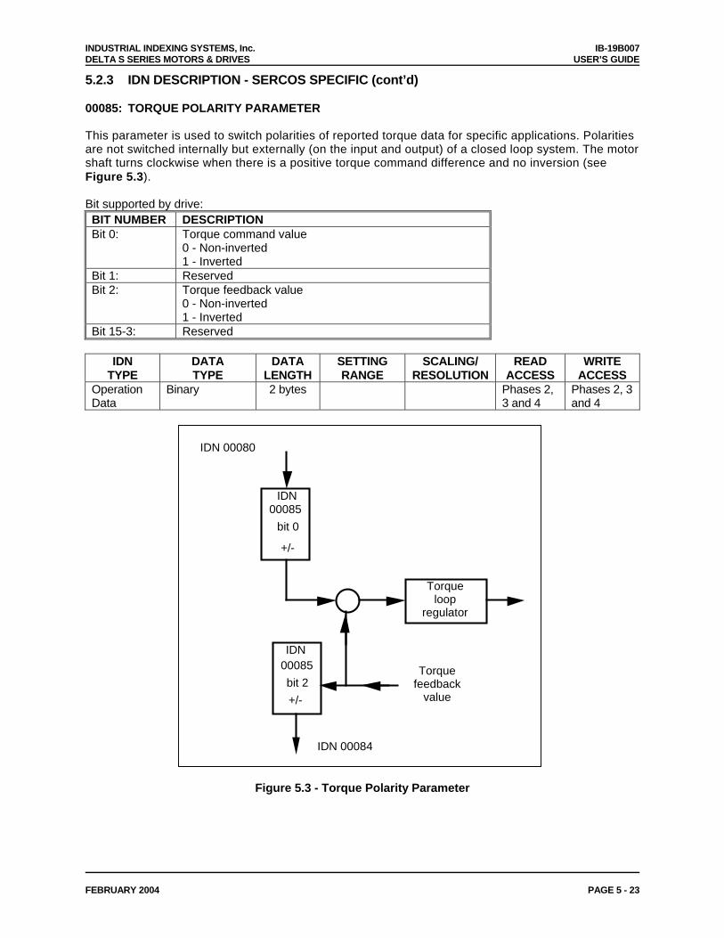
INDUSTRIAL INDEXING SYSTEMS, Inc. IB-19B007 DELTA S SERIES MOTORS & DRIVES USER’S GUIDE
FEBRUARY 2004 PAGE 5 - 23
5.2.3 IDN DESCRIPTION - SERCOS SPECIFIC (cont’d) 00085: TORQUE POLARITY PARAMETER This parameter is used to switch polarities of reported torque data for specific applications. Polarities are not switched internally but externally (on the input and output) of a closed loop system. The motor shaft turns clockwise when there is a positive torque command difference and no inversion (see Figure 5.3). Bit supported by drive: BIT NUMBER DESCRIPTION Bit 0: Torque command value
0 - Non-inverted 1 - Inverted
Bit 1: Reserved Bit 2: Torque feedback value
0 - Non-inverted 1 - Inverted
Bit 15-3: Reserved
IDN TYPE
DATA TYPE
DATA LENGTH
SETTING RANGE
SCALING/ RESOLUTION
READ ACCESS
WRITE ACCESS
Operation Data
Binary 2 bytes Phases 2, 3 and 4
Phases 2, 3 and 4
IDN00085
bit 0
+/-
Torque loop
regulator
IDN00085
bit 2
+/-
Torque feedback
value
IDN 00084
IDN 00080
Figure 5.3 - Torque Polarity Parameter

IB-19B007 INDUSTRIAL INDEXING SYSTEMS, Inc. USER’S GUIDE DELTA S SERIES MOTORS & DRIVES
PAGE 5 - 24 FEBRUARY 2004
5.2.3 IDN DESCRIPTION - SERCOS SPECIFIC (cont’d) 00086: TORQUE DATA SCALING TYPE Defines the scaling option for all torque data. Only the “Percentage Scaling” method is currently supported by the drive. Bit supported by drive: BIT NUMBER DESCRIPTION Bit 2-0: Scaling method
000 - Percentage scaling Bit 3-15: Reserved
IDN
TYPE DATA TYPE
DATA LENGTH
SETTING RANGE
SCALING/ RESOLUTION
READ ACCESS
WRITE ACCESS
Operation Data
Binary 2 bytes Phases 2, 3 and 4
None
00088: RECEIVE TO RECEIVE RECOVERY TIME (tmtsy) Recovery time of the slave after reception of a MDT to switch over to receive the next MST. The master reads this time during CP2 to ensure that the interval will be sufficient between the end of the MDT and the beginning of the MST.
IDN TYPE
DATA TYPE
DATA LENGTH
SETTING RANGE
SCALING/ RESOLUTION
READ ACCESS
WRITE ACCESS
Operation Data
Unsigned Decimal
2 bytes 0 1 s Phases 2, 3 and 4
None
00089: MDT TRANSMISSION STARTING TIME (t2) The MDT transmission starting time determines when the master shall send its MDT during CP3 and CP4, following the MST. This parameter is transferred by the master to the slave during CP2 and becomes active during CP3.
IDN TYPE
DATA TYPE
DATA LENGTH
SETTING RANGE
SCALING/ RESOLUTION
READ ACCESS
WRITE ACCESS
Operation Data
Unsigned Decimal Number
2 bytes 1 - 5000 1 s Phases 2, 3 and 4
Phase 2
00090: COMMAND VALUE PROCEEDING TIME (tmtsg) The time required by the slave to make command values available for a drive after receipt of a MDT. This time is read by the master during CP2 in order to calculate correctly the command value valid time t3 (IDN 00008).
IDN TYPE
DATA TYPE
DATA LENGTH
SETTING RANGE
SCALING/ RESOLUTION
READ ACCESS
WRITE ACCESS
Operation Data
Unsigned Decimal
2 bytes 1 1 s Phases 2, 3 and 4
None

INDUSTRIAL INDEXING SYSTEMS, Inc. IB-19B007 DELTA S SERIES MOTORS & DRIVES USER’S GUIDE
FEBRUARY 2004 PAGE 5 - 25
5.2.3 IDN DESCRIPTION - SERCOS SPECIFIC (cont’d) 00091: BIPOLAR VELOCITY LIMIT VALUE The bipolar velocity limit value describes the maximum allowable velocity in both directions. If the velocity limit value is exceeded, the drive responds by setting the status ‘ncommand > nlimit’ in C3D
(IDN 00013).
IDN TYPE
DATA TYPE
DATA LENGTH
SETTING RANGE
SCALING/ RESOLUTION
READ ACCESS
WRITE ACCESS
Operation Data
Signed Decimal 4 bytes 0-+100.00 0.01% Phases 2, 3 and 4
Phases 2, 3 and 4
00092: BIPOLAR TORQUE LIMIT VALUE (UP-11 The bipolar torque limit value limits the maximum torque symmetrically in both directions. If the torque limit value is exceeded, the drive sets the status ‘T Tlimit’ in C3D (IDN 00013). For this limit to take effect. Torque Limits must be set active in IDN 34334. If this value is set = 0, then IDN 00082, IDN 00084, IDN 34337, and IDN 34339 are valid.
IDN TYPE
DATA TYPE
DATA LENGTH
SETTING RANGE
SCALING/ RESOLUTION
READ ACCESS
WRITE ACCESS
Operation Data
Signed Decimal 2 bytes 0-+100.00 0.01% Phases 2, 3 and 4
Phases 2, 3 and 4
00095: DIAGNOSTIC MESSAGE Not currently supported at this time.
IDN TYPE
DATA TYPE
DATA LENGTH
SETTING RANGE
SCALING/ RESOLUTION
READ ACCESS
WRITE ACCESS
Operation Data
Text Variable Phases 2, 3 and 4
None

IB-19B007 INDUSTRIAL INDEXING SYSTEMS, Inc. USER’S GUIDE DELTA S SERIES MOTORS & DRIVES
PAGE 5 - 26 FEBRUARY 2004
5.2.3 IDN DESCRIPTION - SERCOS SPECIFIC (cont’d) 00096: SLAVE ARRANGEMENT (SLKN) During initialization, the master needs to recognize which physical slaves and their associated drives are present in order to optimize the automatic timeslot computation. The master can request this information from the drives during CP2. By this entry the master recognizes other drives which belong to the same physical slave. Valid drive addresses are all decimal values from 1 to 254, in accordance with hexadecimal values (01)H through (FE)H .
IDN TYPE
DATA TYPE
DATA LENGTH
SETTING RANGE
SCALING/ RESOLUTION
READ ACCESS
WRITE ACCESS
Operation Data
Unsigned Decimal
2 bytes 1 s Phases 2, 3 and 4
Phases 2, 3 and 4
SLKN: Since each Delta S is configured with one drive per slave, then “Next Drives Address“ = “Drive Address“.
Next Drives Address (1 through 255) Drive Address (1 through 255) Example: A drive with an address of “03“ has a value of:
03 03
00097: MASK CLASS 2 DIAGNOSTIC By means of this mask, warnings in class 2 diagnostic can be masked with respect to their effect on the change bit in drive status. When changing masked warnings, the change bit for class 2 diagnostic is not set in the drive status. The mask does not affect the operation data of class 2 diagnostic (see IDN 00012). Setting a bit to 0 masks the effects of the correspond C2D bit on the Class 2 diagnostic change bit.
IDN TYPE
DATA TYPE
DATA LENGTH
SETTING RANGE
SCALING/ RESOLUTION
READ ACCESS
WRITE ACCESS
Operation Data
Binary 2 bytes Phases 2, 3 and 4
Phases 2, 3 and 4

INDUSTRIAL INDEXING SYSTEMS, Inc. IB-19B007 DELTA S SERIES MOTORS & DRIVES USER’S GUIDE
FEBRUARY 2004 PAGE 5 - 27
5.2.3 IDN DESCRIPTION - SERCOS SPECIFIC (cont’d) 00098: MASK CLASS 3 DIAGNOSTIC By means of this mask, condition flags in C3D can be masked with respect to their effect on the change bit in drive status. When masked condition flags change, the change bit for C3D is not set in the drive status. The mask does not affect the operation data of C3D (see IDN 00013). Setting a bit to 0 masks the effects of the correspond C3D bit on the Class 3 diagnostic change bit.
IDN TYPE
DATA TYPE
DATA LENGTH
SETTING RANGE
SCALING/ RESOLUTION
READ ACCESS
WRITE ACCESS
Operation Data
Binary 2 bytes Phases 2, 3 and 4
Phases 2, 3 and 4
00099: RESET CLASS 1 DIAGNOSTIC When this procedure command is received by the drive via the service channel and no error exists, C1D, the interface status, the manufacturer's C1D, the drive shutdown error (drive status bit 13), and the drive shutdown mechanism in the drive are all reset (see IDN 00011, IDN 00014, and IDN 00129).
IDN TYPE
DATA TYPE
DATA LENGTH
SETTING RANGE
SCALING/ RESOLUTION
READ ACCESS
WRITE ACCESS
Procedure Command
Binary 2 bytes Phases 2, 3 and 4
Phases 2, 3 and 4
00124: STANDSTILL WINDOW The standstill window describes the amount of the deviation of the velocity from 0. If the velocity feedback value is within the standstill window the drive sets the status n feedback = 0 in C3D (IDN 00013).
IDN TYPE
DATA TYPE
DATA LENGTH
SETTING RANGE
SCALING/ RESOLUTION
READ ACCESS
WRITE ACCESS
Operation Data
Signed Decimal 4 bytes 0-+100.00 0.01% Phases 2, 3 and 4
Phases 2, 3 and 4
00125: VELOCITY THRESHOLD (nx)
If the velocity feedback value falls below the velocity threshold nx, the drive sets the status
'nfeedback < nx ' in C3D (IDN 00013).
IDN TYPE
DATA TYPE
DATA LENGTH
SETTING RANGE
SCALING/ RESOLUTION
READ ACCESS
WRITE ACCESS
Operation Data
Signed Decimal 4 bytes 0-+100.00 0.01% Phases 2, 3 and 4
Phases 2, 3 and 4

IB-19B007 INDUSTRIAL INDEXING SYSTEMS, Inc. USER’S GUIDE DELTA S SERIES MOTORS & DRIVES
PAGE 5 - 28 FEBRUARY 2004
5.2.3 IDN DESCRIPTION - SERCOS SPECIFIC (cont’d) 00126: TORQUE THRESHOLD (Tx ) If the torque feedback value exceeds the torque threshold T x, the drive sets the status 'T Tx' in C3D (IDN 00013).
IDN TYPE
DATA TYPE
DATA LENGTH
SETTING RANGE
SCALING/ RESOLUTION
READ ACCESS
WRITE ACCESS
Operation Data
Signed Decimal 4 bytes 0-+100.00 0.01% Phases 2, 3 and 4
Phases 2, 3 and 4
00127: CP3 TRANSITION CHECK The master uses this procedure command to instruct the slave to check that all necessary parameters have been transferred for CP3. Otherwise, this procedure command results in an error (see IDN 00021). After the procedure command is performed correctly, the control unit has to cancel the procedure command. The control unit can then activate CP3 in the MST.
IDN TYPE
DATA TYPE
DATA LENGTH
SETTING RANGE
SCALING/ RESOLUTION
READ ACCESS
WRITE ACCESS
Procedure Command
Binary 2 bytes Phases 2, 3 and 4
Phases 2
00128: CP4 TRANSITION CHECK The master uses this procedure command to instruct the slave to check that all necessary parameters have been transferred for CP4. Otherwise, this procedure command results in an error (see IDN 00022). After the procedure command is performed correctly, the control unit has to cancel the procedure command. The control unit can then activate CP4 in the MST.
IDN TYPE
DATA TYPE
DATA LENGTH
SETTING RANGE
SCALING/ RESOLUTION
READ ACCESS
WRITE ACCESS
Procedure Command
Binary 2 bytes Phases 2, 3 and 4
Phases 3

INDUSTRIAL INDEXING SYSTEMS, Inc. IB-19B007 DELTA S SERIES MOTORS & DRIVES USER’S GUIDE
FEBRUARY 2004 PAGE 5 - 29
5.2.3 IDN DESCRIPTION - SERCOS SPECIFIC (cont’d) 00129: MANUFACTURER CLASS 1 DIAGNOSTIC If an error is set in the manufacturer class 1 diagnostic, the manufacturer-specific error bit in class 1 diagnostic (see IDN 00011) is set as well. The drive cancels the manufacturer-specific error and resets to '0' only if the error in manufacturer class 1 diagnostic has been eliminated and on receiving the command 'reset class 1 diagnostic' (see IDN 00099) via the service channel. Bits supported by drive: BIT NUMBER DESCRIPTION Bit 0: Regen Resistor Over-Temperature Fault Bit 1: Regen Resistor Open Fault Bit 2: Brake Sequence Fault Bit 3: Motor Code Invalid Bit 4: Cycle of Power Required Bit 5: Dual Port Communication Error Bit 6: Driver Processor Watchdog Error Bit 7: Absolute Home Error Bit 8: Battery Low Bit 9: Drive Hardware Error Bit 10 - 14: Reserved Bit 15: Fatal System Error
IDN
TYPE DATA TYPE
DATA LENGTH
SETTING RANGE
SCALING/ RESOLUTION
READ ACCESS
WRITE ACCESS
Operation Data
Binary 2 bytes Phases 2, 3 and 4
None
00130: PROBE VALUE 1 POSITIVE EDGE Based on the configure Probe Feedback Source (IDN 33100) the drive stores position feedback value in the measuring cycle in this parameter following the positive edge of the input signal of probe 1 (see IDN 00401). This allows the control unit to read 'probe value 1 positive edge' at a later time.
IDN TYPE
DATA TYPE
DATA LENGTH
SETTING RANGE
SCALING/ RESOLUTION
READ ACCESS
WRITE ACCESS
Operation Data
Signed Decimal 4 bytes -231 - +231 - 1 Phases 2, 3 and 4
None
00131: PROBE VALUE 1 NEGATIVE EDGE Based on the configure Probe Feedback Source (IDN 33100) the drive stores position feedback value in the measuring cycle in this parameter following the negative edge of the input signal of probe 1 (see IDN 00401). This allows the control unit to read 'probe value 1 negative edge' at a later time.
IDN TYPE
DATA TYPE
DATA LENGTH
SETTING RANGE
SCALING/ RESOLUTION
READ ACCESS
WRITE ACCESS
Operation Data
Signed Decimal 4 bytes -231 - +231 - 1 Phases 2, 3 and 4
None

IB-19B007 INDUSTRIAL INDEXING SYSTEMS, Inc. USER’S GUIDE DELTA S SERIES MOTORS & DRIVES
PAGE 5 - 30 FEBRUARY 2004
5.2.3 IDN DESCRIPTION - SERCOS SPECIFIC (cont’d) 00132: PROBE VALUE 2 POSITIVE EDGE Based on the configured Probe Feedback Source (IDN 33100) the drive stores position feedback value in the measuring cycle in this parameter following the positive edge of the input signal of probe 2 (see IDN 00402). This allows the control unit to read 'probe value 2 positive edge' at a later time.
IDN TYPE
DATA TYPE
DATA LENGTH
SETTING RANGE
SCALING/ RESOLUTION
READ ACCESS
WRITE ACCESS
Operation Data
Signed Decimal 4 bytes -231 - +231 - 1 Phases 2, 3 and 4
None
00133: PROBE VALUE 2 NEGATIVE EDGE Based on the configured Probe Feedback Source (IDN 33100) the drive stores position feedback value in the measuring cycle in this parameter following the negative edge of the input signal of probe 2 (see IDN 00402). This allows the control unit to read 'probe value 2 negative edge' at a later time.
IDN TYPE
DATA TYPE
DATA LENGTH
SETTING RANGE
SCALING/ RESOLUTION
READ ACCESS
WRITE ACCESS
Operation Data
Signed Decimal 4 bytes -231 - +231 - 1 Phases 2, 3 and 4
None
00134: MASTER CONTROL WORD Allows reading of the master control word on the control unit screen, via the service channel. (This can be useful during start-up and error recovery.)
IDN TYPE
DATA TYPE
DATA LENGTH
SETTING RANGE
SCALING/ RESOLUTION
READ ACCESS
WRITE ACCESS
Operation Data
Binary 2 bytes Phases 2, 3 and 4
None
00135: DRIVE STATUS WORD Allows reading of the drive status word on the control unit screen, via the service channel. (This can be useful during start-up and error recovery.)
IDN TYPE
DATA TYPE
DATA LENGTH
SETTING RANGE
SCALING/ RESOLUTION
READ ACCESS
WRITE ACCESS
Operation Data
Binary 2 bytes Phases 2, 3 and 4
None

INDUSTRIAL INDEXING SYSTEMS, Inc. IB-19B007 DELTA S SERIES MOTORS & DRIVES USER’S GUIDE
FEBRUARY 2004 PAGE 5 - 31
5.2.3 IDN DESCRIPTION - SERCOS SPECIFIC (cont’d) 00138: BIPOLAR ACCELERATION LIMIT VALUE The bipolar acceleration parameter limits the maximum acceleration ability of the drive symmetrically to the programmed value in both directions.
IDN TYPE
DATA TYPE
DATA LENGTH
SETTING RANGE
SCALING/ RESOLUTION
READ ACCESS
WRITE ACCESS
Operation Data
Signed Decimal 4 bytes 4000 Rev/sec/sec Phases 2, 3 and 4
Phases 2, 3 and 4
00140: CONTROLLER TYPE The operation data of the controller type contains the name of the company and the manufacturer controller type.
IDN TYPE
DATA TYPE
DATA LENGTH
SETTING RANGE
SCALING/ RESOLUTION
READ ACCESS
WRITE ACCESS
Operation Data
Text Variable DELTA-S Phases 2, 3 and 4
None
00142: APPLICATION TYPE The operation data of the application type contains the type of the drive application (e.g., main spindle drive, round axis).
IDN TYPE
DATA TYPE
DATA LENGTH
SETTING RANGE
SCALING/ RESOLUTION
READ ACCESS
WRITE ACCESS
Operation Data
Text Variable Phases 2, 3 and 4
Phases 2, 3 and 4
00143: SYSTEM INTERFACE VERSION The operation data of SYSTEM interface version contains the version of the SYSTEM Interface specification.
IDN TYPE
DATA TYPE
DATA LENGTH
SETTING RANGE
SCALING/ RESOLUTION
READ ACCESS
WRITE ACCESS
Operation Data
Text Variable Phases 2, 3 and 4
None

IB-19B007 INDUSTRIAL INDEXING SYSTEMS, Inc. USER’S GUIDE DELTA S SERIES MOTORS & DRIVES
PAGE 5 - 32 FEBRUARY 2004
5.2.3 IDN DESCRIPTION - SERCOS SPECIFIC (cont’d) 00157: VELOCITY WINDOW The velocity window” relates the current velocity to the velocity command value (IDN 00036). If the current velocity feedback value falls within the calculated velocity window, the drive sets the status 'n feedback = n command' in C3D (IDN 00013).
IDN TYPE
DATA TYPE
DATA LENGTH
SETTING RANGE
SCALING/ RESOLUTION
READ ACCESS
WRITE ACCESS
Operation Data
Signed Decimal 4 bytes 0-100.00 0.01% Phases 2, 3 and 4
Phases 2, 3 and 4
v
t
t
t
Velocity Command Value
Actual Velocity Value
Status 'n feedback = n command'0
1
Velocity WindowVelocity Window
Example: Velocity Command = 50.00 %Velocity Window = 1.00%
The Drive will set the status when the actual velocity value is between49.00% and 51.00%.
Figure 5.4 - Example of Velocity Window
00159: MONITORING WINDOW By means of the monitoring window, the maximum position deviation, as referenced to the active actual position value, can be defined for the position feedback value. When the position error value exceeds the maximum position window value, the drive sets an error for excessive position deviation in C1D (IDN 00011).
IDN TYPE
DATA TYPE
DATA LENGTH
SETTING RANGE
SCALING/ RESOLUTION
READ ACCESS
WRITE ACCESS
Operation Data
Signed Decimal 4 bytes 0-+231 - 1 Phases 2, 3 and 4
Phases 2, 3 and 4

INDUSTRIAL INDEXING SYSTEMS, Inc. IB-19B007 DELTA S SERIES MOTORS & DRIVES USER’S GUIDE
FEBRUARY 2004 PAGE 5 - 33
5.2.3 IDN DESCRIPTION - SERCOS SPECIFIC (cont’d) 00169: PROBE CONTROL PARAMETER This parameter fixes which probes and which edges are activated for the probing cycle procedure command. Only 1 edge (either rising or falling) can be selected for each probe input. Bits supported by drive: BIT NUMBER DESCRIPTION Bit 0: 0 - positive edge is not active
1 - positive edge is active Bit 1: 0 - negative edge is not active
1 - negative edge is active Bit 2: 0 - positive edge is not active
1 - positive edge is active Bit 3: 0 - negative edge is not active
1 - negative edge is active Bit 4 -15: Reserved
IDN
TYPE DATA TYPE
DATA LENGTH
SETTING RANGE
SCALING/ RESOLUTION
READ ACCESS
WRITE ACCESS
Operation Data
Binary 2 bytes Phases 2, 3 and 4
Phases 2, 3 and 4
00170: PROBING CYCLE PROCEDURE COMMAND When the master sets and enables the probing cycle procedure command, the drive reacts on the following parameters:
– Probe 1/2 enable (IDN 00405/00406); and – Probe 1/2 (IDN 00401/00402) as programmed in the probe control parameter (IDN 00169).
While the procedure command is activated the control unit can start multiple measurements. If the control unit does not want any more measurements the control unit cancels the procedure command.
IDN TYPE
DATA TYPE
DATA LENGTH
SETTING RANGE
SCALING/ RESOLUTION
READ ACCESS
WRITE ACCESS
Procedure Command
Binary 2 bytes Phases 2, 3 and 4
Phases 4

IB-19B007 INDUSTRIAL INDEXING SYSTEMS, Inc. USER’S GUIDE DELTA S SERIES MOTORS & DRIVES
PAGE 5 - 34 FEBRUARY 2004
5.2.3 IDN DESCRIPTION - SERCOS SPECIFIC (cont’d) 00179: PROBE STATUS Indicates the latch status of Probe1 and Probe 2 Bits supported by drive: BIT NUMBER DESCRIPTION Bit 0: 0 - positive edge is not latched
1 - positive edge is latched Bit 1: 0 - negative edge is not latched
1 - negative edge is latched Bit 2: 0 - positive edge is not latched
1 - positive edge is latched Bit 3: 0 - negative edge is not latched
1 - negative edge is latched Bit 4 -15: Reserved
IDN TYPE
DATA TYPE
DATA LENGTH
SETTING RANGE
SCALING/ RESOLUTION
READ ACCESS
WRITE ACCESS
Operation Data
Binary 2 bytes Phases 2, 3 and 4
None
00185: LENGTH OF THE CONFIGURABLE DATA RECORD IN THE AT This parameter indicates the maximum length, in bytes, which can be processed in the configurable data record of the AT.
IDN TYPE
DATA TYPE
DATA LENGTH
SETTING RANGE
SCALING/ RESOLUTION
READ ACCESS
WRITE ACCESS
Operation Data
Unsigned Decimal
2 bytes 1 Byte Phases 2, 3 and 4
None
00186: LENGTH OF THE CONFIGURABLE DATA RECORD IN THE MDT This parameter indicates the maximum length, in bytes, which can be processed in the configurable data record of the MDT.
IDN TYPE
DATA TYPE
DATA LENGTH
SETTING RANGE
SCALING/ RESOLUTION
READ ACCESS
WRITE ACCESS
Operation Data
Unsigned Decimal
2 bytes 1 Byte Phases 2, 3 and 4
None
00187: IDN-LIST OF CONFIGURABLE DATA IN THE AT In this list the IDNs of operation data that can be processed by the drive cyclically as feedback values.
IDN TYPE
DATA TYPE
DATA LENGTH
SETTING RANGE
SCALING/ RESOLUTION
READ ACCESS
WRITE ACCESS
Operation Data
IDN Variable Phases 2, 3 and 4
Phases 2, 3 and 4

INDUSTRIAL INDEXING SYSTEMS, Inc. IB-19B007 DELTA S SERIES MOTORS & DRIVES USER’S GUIDE
FEBRUARY 2004 PAGE 5 - 35
5.2.3 IDN DESCRIPTION - SERCOS SPECIFIC (cont’d) 00188: IDN-LIST OF CONFIGURABLE DATA IN THE MDT In this list the IDNs of operation data that can be processed by the drive cyclically as command values.
IDN TYPE
DATA TYPE
DATA LENGTH
SETTING RANGE
SCALING/ RESOLUTION
READ ACCESS
WRITE ACCESS
Operation Data
IDN Variable Phases 2, 3 and 4
Phases 2, 3 and 4
00189: FOLLOWING DISTANCE The drive uses the operation data of this IDN to store the distance between position command value and the position feedback value 1. Calculation of the following distance: following distance = position command value - position feedback value 1
IDN TYPE
DATA TYPE
DATA LENGTH
SETTING RANGE
SCALING/ RESOLUTION
READ ACCESS
WRITE ACCESS
Operation Data
Signed Decimal 4 bytes -231 - +231 - 1 Phases 2, 3 and 4
None
00206: DRIVE ON DELAY TIME When "drive on" and "drive enable" are set (bits 14 and 15 of the master control word) torque is activated at once, but the drive follows the command values after this waiting time has elapsed.
IDN TYPE
DATA TYPE
DATA LENGTH
SETTING RANGE
SCALING/ RESOLUTION
READ ACCESS
WRITE ACCESS
Operation Data
Unsigned Decimal
2 bytes 0 - 216 - 1 1 ms Phases 2, 3 and 4
Phases 2, 3 and 4
00207: DRIVE OFF DELAY TIME After "drive off" (bit 15 of the master control word) is reset and nmin is reached, the torque remains activated in the drive until this waiting time is elapsed.
IDN TYPE
DATA TYPE
DATA LENGTH
SETTING RANGE
SCALING/ RESOLUTION
READ ACCESS
WRITE ACCESS
Operation Data
Unsigned Decimal
2 bytes 0 - 216 - 1 1 ms Phases 2, 3 and 4
Phases 2, 3 and 4
00300: REAL-TIME CONTROL BIT 1 Contains the state of the control signal defined in IDN 00301 in Bit 0.
IDN TYPE
DATA TYPE
DATA LENGTH
SETTING RANGE
SCALING/ RESOLUTION
READ ACCESS
WRITE ACCESS
Operation Data
Binary 2 bytes Phases 2, 3 and 4
None

IB-19B007 INDUSTRIAL INDEXING SYSTEMS, Inc. USER’S GUIDE DELTA S SERIES MOTORS & DRIVES
PAGE 5 - 36 FEBRUARY 2004
5.2.3 IDN DESCRIPTION - SERCOS SPECIFIC (cont’d) 00301: ALLOCATION OF REAL-TIME CONTROL BIT 1 Assigns a control signal to the real-time control bit 1 by writing the IDN of the control signal to this IDN. After the allocation the assigned signal appears in the real-time control bit 1. Valid IDN’s are (IDN 00405, 00406). Writing a value of zero disables Real Time Control Bit 1. (Default)
IDN TYPE
DATA TYPE
DATA LENGTH
SETTING RANGE
SCALING/ RESOLUTION
READ ACCESS
WRITE ACCESS
Operation Data
IDN 2 bytes Phases 2, 3 and 4
Phases 2, 3 and 4
00302: REAL-TIME CONTROL BIT 2 Contains the state of the control signal defined in IDN 00303 in Bit 0.
IDN TYPE
DATA TYPE
DATA LENGTH
SETTING RANGE
SCALING/ RESOLUTION
READ ACCESS
WRITE ACCESS
Operation Data
Binary 2 bytes Phases 2, 3 and 4
None
00303: ALLOCATION OF REAL-TIME CONTROL BIT 2 Assigns a control signal to the real-time control bit 2 by writing the IDN of the control signal to this IDN. After the allocation the assigned signal appears in the real-time control bit 2. Valid IDN’s are (IDN 00405, 00406). Writing a value of zero disables Real Time Control Bit 2. (Default)
IDN TYPE
DATA TYPE
DATA LENGTH
SETTING RANGE
SCALING/ RESOLUTION
READ ACCESS
WRITE ACCESS
Operation Data
IDN 2 bytes Phases 2, 3 and 4
Phases 2, 3 and 4
00304: REAL-TIME STATUS BIT 1 Contains the state of the status signal defined in IDN 00305 in Bit 0.
IDN TYPE
DATA TYPE
DATA LENGTH
SETTING RANGE
SCALING/ RESOLUTION
READ ACCESS
WRITE ACCESS
Operation Data
Binary 2 bytes Phases 2, 3 and 4
None

INDUSTRIAL INDEXING SYSTEMS, Inc. IB-19B007 DELTA S SERIES MOTORS & DRIVES USER’S GUIDE
FEBRUARY 2004 PAGE 5 - 37
5.2.3 IDN DESCRIPTION - SERCOS SPECIFIC (cont’d) 00305: ALLOCATION OF REAL-TIME STATUS BIT 1 Assigns a control signal to the real-time status bit 1 by writing the IDN of the control signal to this IDN. After the allocation the assigned signal appears in the real-time status bit 1. Valid IDN’s are (IDN 00401, 00402, 00409, 00410, 00411, 00412, 33501 - 33516). Writing a value of zero disables real time status bit 1. (Default)
IDN TYPE
DATA TYPE
DATA LENGTH
SETTING RANGE
SCALING/ RESOLUTION
READ ACCESS
WRITE ACCESS
Operation Data
IDN 2 bytes Phases 2, 3 and 4
Phases 2, 3 and 4
00306: REAL-TIME STATUS BIT 2 Contains the state of the status signal defined in IDN 00307 in Bit 0.
IDN TYPE
DATA TYPE
DATA LENGTH
SETTING RANGE
SCALING/ RESOLUTION
READ ACCESS
WRITE ACCESS
Operation Data
Binary 2 bytes Phases 2, 3 and 4
None
00307: ALLOCATION OF REAL-TIME STATUS BIT 2 Assigns a control signal to the real-time status bit 2 by writing the IDN of the control signal to this IDN. After the allocation the assigned signal appears in the real-time status bit 2. Valid IDN’s are (IDN 00401, 00402, 00409, 00410, 00411, 00412, 33501 - 33516). Writing a value of zero disables real time status bit 2. (Default)
IDN TYPE
DATA TYPE
DATA LENGTH
SETTING RANGE
SCALING/ RESOLUTION
READ ACCESS
WRITE ACCESS
Operation Data
IDN 2 bytes Phases 2, 3 and 4
Phases 2, 3 and 4
00401: PROBE 1 Contains the state of the Probe 1 Input in Bit 0.
IDN TYPE
DATA TYPE
DATA LENGTH
SETTING RANGE
SCALING/ RESOLUTION
READ ACCESS
WRITE ACCESS
Operation Data
Binary 2 bytes Phases 2, 3 and 4
None

IB-19B007 INDUSTRIAL INDEXING SYSTEMS, Inc. USER’S GUIDE DELTA S SERIES MOTORS & DRIVES
PAGE 5 - 38 FEBRUARY 2004
5.2.3 IDN DESCRIPTION - SERCOS SPECIFIC (cont’d) 00402: PROBE 2 Contains the state of the Probe 2 Input in Bit 0.
IDN TYPE
DATA TYPE
DATA LENGTH
SETTING RANGE
SCALING/ RESOLUTION
READ ACCESS
WRITE ACCESS
Operation Data
Binary 2 bytes Phases 2, 3 and 4
None
00405: PROBE 1 ENABLE Probe 1 enable is checked by the drive only if the procedure commands "probing cycle" (IDN 00170) is active. For a new probing cycle with the same edge of probe 1 the control unit has to reset probe 1 enable to "0" and set it to "1". (For more details see IDN 00179.)
IDN TYPE
DATA TYPE
DATA LENGTH
SETTING RANGE
SCALING/ RESOLUTION
READ ACCESS
WRITE ACCESS
Operation Data
Binary 2 bytes Phases 2, 3 and 4
Phases 4
00406: PROBE 2 ENABLE Probe 2 enable is checked by the drive only if the procedures command "probing cycle" (IDN 00170) is active. For a new probing cycle with the same edge of probe 2 the control unit has to reset probe 2 enable to "0" and set it to "1". (For more details see IDN 00179.)
IDN TYPE
DATA TYPE
DATA LENGTH
SETTING RANGE
SCALING/ RESOLUTION
READ ACCESS
WRITE ACCESS
Operation Data
Binary 2 bytes Phases 2, 3 and 4
Phases 4
00409: PROBE 1 POSITIVE LATCHED This parameter is used to assign an IDN to probe 1 positive latched. This allows assigning the status "probe 1 positive latched" to a real-time status bit (see IDN 00305). Bit 0 of this parameter is set by the drive only if the procedure command "probing cycle" (IDN 00170) is active, the signal "probe 1 enable" (IDN 00405) is set to 1 and the positive edge of "probe 1" (IDN 00401) is announced. Simultaneously the drive stores the position feedback value in "probe 1 positive edge" (IDN 00130). The drive resets this bit when the control unit cancels the procedure command "probing cycle" or when probe 1 enable is reset to 0. Bit 0 is defined for operation data only. (For more details see IDN 00179.)
IDN TYPE
DATA TYPE
DATA LENGTH
SETTING RANGE
SCALING/ RESOLUTION
READ ACCESS
WRITE ACCESS
Operation Data
Binary 2 bytes Phases 2, 3 and 4
None

INDUSTRIAL INDEXING SYSTEMS, Inc. IB-19B007 DELTA S SERIES MOTORS & DRIVES USER’S GUIDE
FEBRUARY 2004 PAGE 5 - 39
5.2.3 IDN DESCRIPTION - SERCOS SPECIFIC (cont’d) 00410: PROBE 1 NEGATIVE LATCHED This parameter is used to assign an IDN to probe 1 negative latched. This allows assigning the status "probe 1 negative latched" to a real-time status bit (see IDN 00305). Bit 0 of this parameter is set by the drive only if the procedure command "probing cycle" (IDN 00170) is active, the signal "probe 1 enable" (IDN 00405) is set to 1 and the negative edge of "probe 1" (IDN 00401) is announced. Simultaneously the drive stores the position feedback value in "probe 1 negative edge" (IDN 00131). The drive resets this bit when the control unit cancels the procedure command "probing cycle" or when probe 1 enable is reset to 0. Bit 0 is defined for operation data only. (For more details see IDN 00179.)
IDN TYPE
DATA TYPE
DATA LENGTH
SETTING RANGE
SCALING/ RESOLUTION
READ ACCESS
WRITE ACCESS
Operation Data
Binary 2 bytes Phases 2, 3 and 4
None
00411: PROBE 2 POSITIVE LATCHED This parameter is used to assign an IDN to probe 2 positive latched. This allows assigning the status "probe 2 positive latched" to a real-time status bit (see IDN 00305). Bit 0 of this parameter is set by the drive only if the procedure command "probing cycle" (IDN 00170) is active, the signal "probe 2 enable" (IDN 00406) is set to 1 and the positive edge of "probe 2" (IDN 00402) is announced. Simultaneously the drive stores the position feedback value in "probe 2 positive edge" (IDN 00132). The drive resets this bit when the control unit cancels the procedure command "probing cycle" or when probe 2 enable is reset to 0. Bit 0 is defined for operation data only. (For more details see IDN 00179.)
IDN TYPE
DATA TYPE
DATA LENGTH
SETTING RANGE
SCALING/ RESOLUTION
READ ACCESS
WRITE ACCESS
Operation Data
Binary 2 bytes Phases 2, 3 and 4
None
00412: PROBE 2 NEGATIVE LATCHED This parameter is used to assign an IDN to probe 2 negative latched. This allows assigning the status "probe 2 negative latched" to a real-time status bit (see IDN 00305). Bit 0 of this parameter is set by the drive only if the procedure command "probing cycle" (IDN 00170) is active, the signal "probe 2 enable" (IDN 00406) is set to 1 and the negative edge of "probe 2" (IDN 00402) is announced. Simultaneously the drive stores the position feedback value in "probe 2 negative edge" (IDN 00133). The drive resets this bit when the control unit cancels the procedure command "probing cycle" or when probe 2 enable is reset to 0. Bit 0 is defined for operation data only. (For more details see IDN 00179.)
IDN TYPE
DATA TYPE
DATA LENGTH
SETTING RANGE
SCALING/ RESOLUTION
READ ACCESS
WRITE ACCESS
Operation Data
Binary 2 bytes Phases 2, 3 and 4
None

IB-19B007 INDUSTRIAL INDEXING SYSTEMS, Inc. USER’S GUIDE DELTA S SERIES MOTORS & DRIVES
PAGE 5 - 40 FEBRUARY 2004
5.2.4 IDN DESCRIPTION - IIS SPECIFIC 33000: DIGITAL OUTPUTS The state of the digital output can be set via this parameter. If the corresponding bit in the Output Function (IDN 33020) is set to 0 then the bit will be written to the Digital Output hardware. See IDN 33040 for the hardware output bit structure.
IDN TYPE
DATA TYPE
DATA LENGTH
SETTING RANGE
SCALING/ RESOLUTION
READ ACCESS
WRITE ACCESS
Operation Data
Binary 0-65535 Phases 2, 3 and 4
Phase 4
33020: OUTPUT FUNCTION Determines the controlling function for the Digital Output. Bit = 0: corresponding bit in IDN 33000 is written to output. Bit = 1: corresponding bit in IDN 33040 is written to output.
IDN TYPE
DATA TYPE
DATA LENGTH
SETTING RANGE
SCALING/ RESOLUTION
READ ACCESS
WRITE ACCESS
Operation Data
Binary 0-65535 Phases 2, 3 and 4
Phases 2, 3 and 4
33040: DIGITAL OUTPUT HARDWARE STATE The state of the Digital Output Hardware can be viewed by this parameter. The hardware state is determined by the states of IDN 33000, IDN 33020, IDN 33109 and IDN 33110. Bit supported by drive: BIT NUMBER DESCRIPTION Bit 0: Output 1 (Brake Output) Bit 1: Output 2 Bit 2: Output 3 Bit 3: Output 4 Bit 4: Output 5 Bit 5: Output 6 Bit 6: Output 7 Bit 7: Output 8 Bit 8: Output 9 Bit 9: Output 10 Bit 10: Output 11 Bit 11: Output 12 Bit 12: Output 13 Bit 13: Output 14 Bit 14: Output 15 Bit 15: Output 16
IDN
TYPE DATA TYPE
DATA LENGTH
SETTING RANGE
SCALING/ RESOLUTION
READ ACCESS
WRITE ACCESS
Operation Data
Binary 2 bytes Phases 2, 3 and 4
None

INDUSTRIAL INDEXING SYSTEMS, Inc. IB-19B007 DELTA S SERIES MOTORS & DRIVES USER’S GUIDE
FEBRUARY 2004 PAGE 5 - 41
5.2.4 IDN DESCRIPTION - IIS SPECIFIC (cont’d) 33100: PLS SOURCE Determines which source the PLS Angle follows. Setting the PLS source initializes the PLS Angle, resets the PLS Mask (IDN 33109), PLS Preset (IDN 33109) and PLS Offset, and Clears the PLS Bit table. Bit 0 = 0 PLS Angle follows Position Feedback 1 Bit 1 = 0 PLS Angle follows Position Feedback 2 Note: The PLS Angle will not follow any source until IDN 33100 is written to.
IDN TYPE
DATA TYPE
DATA LENGTH
SETTING RANGE
SCALING/ RESOLUTION
READ ACCESS
WRITE ACCESS
Operation Data
Binary 2 bytes 0-1 Phases 2, 3 and 4
Phases 2, 3 and 4
33101: CURRENT PLS ANGLE Reads the current PLS Angle from the drive. The PLS Angle is only updated after a PLS Source has been selected.
IDN TYPE
DATA TYPE
DATA LENGTH
SETTING RANGE
SCALING/ RESOLUTION
READ ACCESS
WRITE ACCESS
Operation Data
Signed Decimal 4 bytes 0 - PLS Cycle 1 bit Phases 2, 3 and 4
None
33103: PLS CYCLE Sets the size of the PLS Cycle.
IDN TYPE
DATA TYPE
DATA LENGTH
SETTING RANGE
SCALING/ RESOLUTION
READ ACCESS
WRITE ACCESS
Operation Data
Signed Decimal 4 bytes 4 to 223 1 bit Phases 2, 3 and 4
Phases 2, 3 and 4
33104: PLS PRESET Sets the current PLS Angle to the PLS Preset Value.
IDN TYPE
DATA TYPE
DATA LENGTH
SETTING RANGE
SCALING/ RESOLUTION
READ ACCESS
WRITE ACCESS
Operation Data
Signed Decimal 4 bytes 0 - PLS Cycle 1 bit Phases 2, 3 and 4
Phases 2, 3 and 4

IB-19B007 INDUSTRIAL INDEXING SYSTEMS, Inc. USER’S GUIDE DELTA S SERIES MOTORS & DRIVES
PAGE 5 - 42 FEBRUARY 2004
5.2.4 IDN DESCRIPTION - IIS SPECIFIC (cont’d) 33105: PLS OFFSET Offsets the PLS Angle by the PLS Offset value.
IDN TYPE
DATA TYPE
DATA LENGTH
SETTING RANGE
SCALING/ RESOLUTION
READ ACCESS
WRITE ACCESS
Operation Data
Signed Decimal 4 bytes -231 - +231 - 1 1 bit Phases 2, 3 and 4
Phases 2, 3 and 4
33106: PLS ADVANCE Reserved
IDN TYPE
DATA TYPE
DATA LENGTH
SETTING RANGE
SCALING/ RESOLUTION
READ ACCESS
WRITE ACCESS
Operation Data
Signed Decimal 2 bytes 1 bit Phases 2, 3 and 4
Phases 2, 3 and 4
33107: CLEAR PLS Clears the corresponding bits in the PLS output table. See IDN 33040 for bit definition.
IDN TYPE
DATA TYPE
DATA LENGTH
SETTING RANGE
SCALING/ RESOLUTION
READ ACCESS
WRITE ACCESS
Operation Data
Binary 2 bytes Phases 2, 3 and 4
Phases 2, 3 and 4
33108: SET PLS ANGLE For all bits set in the “PLS output bits” sets corresponding bits to 1 between the On Angle and Off Angle. Of Mode = Reset then all other corresponding bits in the cycle are set to 0. Structure: PLS output bits 2 bytes (See IDN 33040 for bit definition) Mode 2 bytes (Append: Bit 0 = 1, Reset: Bit 0 = 0) On Angle 4 bytes (0 < Range < PLS CYCLE (IDN 33103)) Off Angle 4 bytes (0 < Range < PLS CYCLE (IDN 33103))
IDN TYPE
DATA TYPE
DATA LENGTH
SETTING RANGE
SCALING/ RESOLUTION
READ ACCESS
WRITE ACCESS
Operation Data
Text Variable Phases 2, 3 and 4
Phases 2, 3 and 4

INDUSTRIAL INDEXING SYSTEMS, Inc. IB-19B007 DELTA S SERIES MOTORS & DRIVES USER’S GUIDE
FEBRUARY 2004 PAGE 5 - 43
5.2.4 IDN DESCRIPTION - IIS SPECIFIC (cont’d) 33109: PLS MASK Enables the corresponding bits it the PLS Output to follow the PLS Bit table. (See IDN 33040 for bit definition.) Bit = 0: PLS Output bit disabled. Corresponding PLS Output Bit holds last state. Bit = 1: PLS Output bit Enabled. Corresponding PLS Output Bit updates as PLS Angle is updated.
IDN TYPE
DATA TYPE
DATA LENGTH
SETTING RANGE
SCALING/ RESOLUTION
READ ACCESS
WRITE ACCESS
Operation Data
Binary 2 bytes Phases 2, 3 and 4
Phases 2, 3 and 4
33110: PLS OUTPUT The state of the PLS Outputs can be read via this parameter. (See IDN 33040 for bit definition.)
IDN TYPE
DATA TYPE
DATA LENGTH
SETTING RANGE
SCALING/ RESOLUTION
READ ACCESS
WRITE ACCESS
Operation Data
Binary 2 bytes Phases 2, 3 and 4
None
33111: SET PLS STATE By definition of the PLS MASK (IDN 33109), if a PLS Output bit is disabled in the PLS Mask the bit will hold its last state. This IDN allows the last state of the bit to be forced to 1. If a bit = 1 in this operation data and its corresponding bit in the PLS Mask = 0, then the PLS Output bit will be set = 1.
IDN TYPE
DATA TYPE
DATA LENGTH
SETTING RANGE
SCALING/ RESOLUTION
READ ACCESS
WRITE ACCESS
Operation Data
Binary 2 bytes Phases 2, 3 and 4
Phase 4
33112: CLEAR PLS STATE By definition of the PLS MASK (IDN 33109), if a PLS Output bit is disabled in the PLS Mask the bit will hold its last state. This IDN allows the last state of the bit to be forced to 0. If a bit = 1 in this operation data and its corresponding bit in the PLS Mask = 0, then the PLS Output bit will be set = 0.
IDN TYPE
DATA TYPE
DATA LENGTH
SETTING RANGE
SCALING/ RESOLUTION
READ ACCESS
WRITE ACCESS
Operation Data
Binary 2 bytes Phases 2, 3 and 4
Phase 4

IB-19B007 INDUSTRIAL INDEXING SYSTEMS, Inc. USER’S GUIDE DELTA S SERIES MOTORS & DRIVES
PAGE 5 - 44 FEBRUARY 2004
5.2.4 IDN DESCRIPTION - IIS SPECIFIC (cont’d) 33500: DIGITAL INPUTS Reads the State of the Digital Inputs on the Drive. Bit supported by drive: BIT NUMBER DESCRIPTION Bit 0: Input 1 (See IDN 33517) Bit 1: Input 2 Bit 2: Input 3 Bit 3: Input 4 Bit 4: Input 5 Bit 5: Input 6 Bit 6: Input 7 Bit 7: Input 8 Bit 8: Input 9 Bit 9: Input 10 Bit 10: Input 11 Bit 11: Input 12 Bit 12: Input 13 Bit 13: Input 14 Bit 14: Input 15 Bit 15: Input 16
IDN
TYPE DATA TYPE
DATA LENGTH
SETTING RANGE
SCALING/ RESOLUTION
READ ACCESS
WRITE ACCESS
Operation Data
Binary 2 bytes Phases 2, 3 and 4
None
33501 - 33516: DIGITAL INPUT0 - DIGITAL INPUT15 Read the State of the signal on the Drive into Bit 0. This IDN was created so that the digital inputs could be mapped to the Real Time Status Bits.
IDN TYPE
DATA TYPE
DATA LENGTH
SETTING RANGE
SCALING/ RESOLUTION
READ ACCESS
WRITE ACCESS
Operation Data
Binary 2 bytes Phases 2, 3 and 4
None
33517: DIGITAL INPUT 0 CONFIGURATION Allows mapping of the Probe bits into the Digital Input 0 Bit. Valid Values: 0: Brake Input 1: Probe 1 State 2: Probe 2 State
IDN TYPE
DATA TYPE
DATA LENGTH
SETTING RANGE
SCALING/ RESOLUTION
READ ACCESS
WRITE ACCESS
Operation Data
Binary 2 bytes 0 - 2 Phases 2, 3 and 4
Phases 2, 3 and 4

INDUSTRIAL INDEXING SYSTEMS, Inc. IB-19B007 DELTA S SERIES MOTORS & DRIVES USER’S GUIDE
FEBRUARY 2004 PAGE 5 - 45
5.2.4 IDN DESCRIPTION - IIS SPECIFIC (cont’d) 33600: ANALOG INPUT 1 Read the counts from the Analog Input 1. The value of the A/D is shifted up to a 16-bit value so that the range is the same for either the 10-bit (standard) or the 14-bit (optional) A/D.
IDN TYPE
DATA TYPE
DATA LENGTH
SETTING RANGE
SCALING/ RESOLUTION
READ ACCESS
WRITE ACCESS
Operation Data
Signed Decimal 2 bytes -215 - +215 - 1 10-bit or 14-bit A/D shifted up.
Phases 2, 3 and 4
None
33601: ANALOG INPUT 2 Read the counts from the Analog Input 2. The value of the A/D is shifted up to a 16bit value.
IDN TYPE
DATA TYPE
DATA LENGTH
SETTING RANGE
SCALING/ RESOLUTION
READ ACCESS
WRITE ACCESS
Operation Data
Signed Decimal 2 bytes -215 - +215 - 1 10-bit or 14-bit A/D shifted up.
Phases 2, 3 and 4
None
33700: ALARM HISTORY The drive maintains a list of the up to 15 Alarm Faults Codes and details about the state of the drive when the faults happened. This IDN returns only the list of up to 15 faults. See IDN 34808 if the details of the faults are desired.
IDN TYPE
DATA TYPE
DATA LENGTH
SETTING RANGE
SCALING/ RESOLUTION
READ ACCESS
WRITE ACCESS
Operation Data
Unsigned Decimal
Variable 2 byte each
Phases 2, 3 and 4
None
34202: LOAD INERTIA RATIO (AJ2) Sets the baseline frequency response of the drive using the ratio of the load inertia/motor inertia for a rigidly coupled load. If the load is not rigidly coupled, the value entered may vary from the calculated value. If the value is set too high, the motor and the drive may become unstable and oscillate. This parameter is set automatically during auto tuning.
IDN TYPE
DATA TYPE
DATA LENGTH
SETTING RANGE
SCALING/ RESOLUTION
READ ACCESS
WRITE ACCESS
Operation Data
Unsigned Decimal
2 bytes 0~100 1 Times Phases 2, 3 and 4
Phases 2, 3 and 4

IB-19B007 INDUSTRIAL INDEXING SYSTEMS, Inc. USER’S GUIDE DELTA S SERIES MOTORS & DRIVES
PAGE 5 - 46 FEBRUARY 2004
5.2.4 IDN DESCRIPTION - IIS SPECIFIC (cont’d) 34203: HIGH FREQUENCY RESPONSE (AJ3) Sets the high frequency response of the driver. The higher the number, the more responsive. If the value is set too high, the motor may become unstable and oscillate. The value in IDN 34203 is unit less and works in concert with IDN 34202 (AJ2). This parameter is set automatically during auto tuning.
IDN TYPE
DATA TYPE
DATA LENGTH
SETTING RANGE
SCALING/ RESOLUTION
READ ACCESS
WRITE ACCESS
Operation Data
Unsigned Decimal
2 bytes 0.1~20.0 0.1 Phases 2, 3 and 4
Phases 2, 3 and 4
34204: POSITION LOOP DC GAIN (AJ4) Sets the DC gain of the position control loop. A higher value in IDN 34204 results in stiffer, faster response. If the value is set too high, the motor and drive may become unstable and oscillate. This parameter is set automatically during auto tuning.
IDN TYPE
DATA TYPE
DATA LENGTH
SETTING RANGE
SCALING/ RESOLUTION
READ ACCESS
WRITE ACCESS
Operation Data
Unsigned Decimal
2 bytes 1~200 1 rad/sec Phases 2, 3 and 4
Phases 2, 3 and 4
34207: ZERO SPEED GAIN REDUCTION (AJ7) Set the amount of gain reduction at zero speed. The gain is reduced when the motor is below the speed set in IDN 34207 and at the set values when the speed is above IDN 34207.
IDN TYPE
DATA TYPE
DATA LENGTH
SETTING RANGE
SCALING/ RESOLUTION
READ ACCESS
WRITE ACCESS
Operation Data
Unsigned Decimal
0 0~10000 1 Phases 2, 3 and 4
Phases 2, 3 and 4
34208: FEED FORWARD GAIN (AJ8) Sets the feed forward gain in the position loop. A value of 1.0 results in 0.0 following error. Less than 1.0 will produce a lag between the actual motor position and the commanded position and greater than 1.0 produces a lead. The lead or lag will be proportion to speed at non- 1.0 setting.
IDN TYPE
DATA TYPE
DATA LENGTH
SETTING RANGE
SCALING/ RESOLUTION
READ ACCESS
WRITE ACCESS
Operation Data
Unsigned Decimal
2 bytes 0~2.0 1 Time Phases 2, 3 and 4
Phases 2, 3 and 4

INDUSTRIAL INDEXING SYSTEMS, Inc. IB-19B007 DELTA S SERIES MOTORS & DRIVES USER’S GUIDE
FEBRUARY 2004 PAGE 5 - 47
5.2.4 IDN DESCRIPTION - IIS SPECIFIC (cont’d)
34209: SECONDARY FILTER (AJ9) Sets the notch frequency of a velocity loop anti-resonance filter. This filter can be used to cancel machine or servo resonance.
IDN TYPE
DATA TYPE
DATA LENGTH
SETTING RANGE
SCALING/ RESOLUTION
READ ACCESS
WRITE ACCESS
Operation Data
Unsigned Decimal
2 bytes 400~20000 1 rad/s Phases 2, 3 and 4
Phases 2, 3 and 4
34302: MOTOR CODE (UP-02)
Sets the internal driver parameters corresponding to the motor code. See Appendix A for motor codes. The driver power must be cycled to register a change in this parameter value. Power must be turned off then ON for this change to take effect. Writing the same value as already stored in the drive does not require the power to be cycled.
IDN TYPE
DATA TYPE
DATA LENGTH
SETTING RANGE
SCALING/ RESOLUTION
READ ACCESS
WRITE ACCESS
Operation Data
Hexidecimal 2 bytes 0000~FFFF Phases 2, 3 and 4
Phases 2, 3 and 4
34303: RESOLVER CABLE LENGTH (UP-03) Set the driver resolver cable length compensation.
IDN TYPE
DATA TYPE
DATA LENGTH
SETTING RANGE
SCALING/ RESOLUTION
READ ACCESS
WRITE ACCESS
Operation Data
Unsigned Decimal
2 bytes 0~120 1 Meter Phases 2, 3 and 4
Phases 2, 3 and 4
34304: GEAR RATIO DENOMINATOR FOR THE PULSE OUTPUT (UP-04) The output pulse (APD and BPD) is multiplied by UP05/UP04 and then sent to the APD and BPD output pins of the encoder output. This balue is the ratio of the desired output counts of the encoder output and the internal raw processing counts of the driver.
IDN TYPE
DATA TYPE
DATA LENGTH
SETTING RANGE
SCALING/ RESOLUTION
READ ACCESS
WRITE ACCESS
Operation Data
Unsigned Decimal
2 bytes 1~32767 Phases 2, 3 and 4
Phases 2, 3 and 4
34305: GEAR RATIO NUMERATOR FOR THE PULSE OUTPUT (UP-05) Combined with parameter 0204H.
IDN TYPE
DATA TYPE
DATA LENGTH
SETTING RANGE
SCALING/ RESOLUTION
READ ACCESS
WRITE ACCESS
Operation Data
Unsigned Decimal
2 bytes 1~32767 Phases 2, 3 and 4
Phases 2, 3 and 4

IB-19B007 INDUSTRIAL INDEXING SYSTEMS, Inc. USER’S GUIDE DELTA S SERIES MOTORS & DRIVES
PAGE 5 - 48 FEBRUARY 2004
5.2.4 IDN DESCRIPTION - IIS SPECIFIC (cont’d) 34315: ABSOLUTE POSITION CLEAR (UP-05) Sets the Absolute Position based on the following type: 0: Makes current position of motor equal to 0. 1: Makes the current motor shaft rotation the 0 rotation while preserving the MARKER.
IDN TYPE
DATA TYPE
DATA LENGTH
SETTING RANGE
SCALING/ RESOLUTION
READ ACCESS
WRITE ACCESS
Operation Data
Binary 2 bytes 0 - 1 Phases 2, 3 and 4
Phases 2, 3 and 4
34316: BRAKE MODE Selects the type of brake sequencing to be done when the drive is disabled. Also, defines the Mode of Input 0 and Output 0. Refer to Sections 10 and 11 for more details. 0: No Brake 1: Dynamic Brake 2: Mechanical Holding Brake
IDN TYPE
DATA TYPE
DATA LENGTH
SETTING RANGE
SCALING/ RESOLUTION
READ ACCESS
WRITE ACCESS
Operation Data
Hexidecimal 2 0~2 Phases 2, 3 and 4
Phases 2, 3 and 4
34318: AUXILIARY ENCODER INPUT PULSE TYPE (UP-18) Sets the type of pulse sequence and polarity of the Auxiliary Encoder Pulse inputs. 00: Pulse, Pulse Decoding where FMA increments position and FMB decrements position. 01: Quadrature decoding of FMA and FMB with FMA Leading FMB for incrementing command position.
Quadrature decoding effectively multiplies the input frequency by 4 times. 02: Pulse and direction decoding where FMA is pulse train and FMB is direction. FMB OFF increments
the position and ON decrements the position. 10: Pulse, Pulse Decoding where FMB increments position and FMA decrements position. 11: Quadrature decoding of FMA and FMB with FMB Leading FMA for incrementing command position.
Quadrature decoding effectively multiplies the input frequency by 4 times. 12: Pulse and direction decoding where FMA is pulse train and FMB is direction. FMB ON increments
the position and OFF decrements the Position.
IDN TYPE
DATA TYPE
DATA LENGTH
SETTING RANGE
SCALING/ RESOLUTION
READ ACCESS
WRITE ACCESS
Operation Data
Hexidecimal 2 00 - 12 Phases 2, 3 and 4
Phases 2, 3 and 4

INDUSTRIAL INDEXING SYSTEMS, Inc. IB-19B007 DELTA S SERIES MOTORS & DRIVES USER’S GUIDE
FEBRUARY 2004 PAGE 5 - 49
5.2.4 IDN DESCRIPTION - IIS SPECIFIC (cont’d) 34319: PULSE OUTPUT PULSE TYPE (UP-19) Sets the type of pulse output sequence and polarity of the pulse output. The pulse output pulse train is coded as the incremental position scaled by Gear Ratio parameters 0205H and 0204H. 0x00: Pulse, Pulse encoding where APD pulse when the actual position increments and BPD pulses
when the actual position decrements. 0x01: Quadrature encoding of APD and BPD with APD Leading BPD for incremental actual position.
Each edge of the two pulse Trains are counted as an output bit change. 0x10: Pulse, Pulse encoding where BPD pulse when the actual position increments and APD pulses
when the actual position decrements. 0x11: Quadrature encoding of APD and BPD with BPD Leading APD for Incremental actual position.
Each edge of the two pulse Trains are counted as an output bit change.
IDN TYPE
DATA TYPE
DATA LENGTH
SETTING RANGE
SCALING/ RESOLUTION
READ ACCESS
WRITE ACCESS
Operation Data
Hexadecimal Number
2 0x00~0x11 Phases 2, 3 and 4
Phases 2, 3 and 4
34325: MONITOR OUTPUT FUNCTION Selects the speed and torque output and polarity of the monitor test point. The first byte selects the MON output function. 0xX0: TORQUE 0xX1: SPEED The second byte selects the polarity of the monitor output. 0x0X: NORMAL 0x1X: INVERT
IDN TYPE
DATA TYPE
DATA LENGTH
SETTING RANGE
SCALING/ RESOLUTION
READ ACCESS
WRITE ACCESS
Operation Data
Hexadecimal Number
2 0x00~0x11 Phases 2, 3 and 4
Phases 2, 3 and 4
34328: HOLDING BRAKE THRESHOLD (UP-28) When IDN34316 is set to 0, IDN 34328 has no effect. When IDN 34316 is set to 1, the mechanical break is applied when the motor speed falls below UP28. UP28 is scaled in % of rated speed.
IDN TYPE
DATA TYPE
DATA LENGTH
SETTING RANGE
SCALING/ RESOLUTION
READ ACCESS
WRITE ACCESS
Operation Data
Unsigned Decimal
2 0~100 0.1% Phases 2, 3 and 4
Phases 2, 3 and 4

IB-19B007 INDUSTRIAL INDEXING SYSTEMS, Inc. USER’S GUIDE DELTA S SERIES MOTORS & DRIVES
PAGE 5 - 50 FEBRUARY 2004
5.2.4 IDN DESCRIPTION - IIS SPECIFIC (cont’d) 34330: EXTERNAL REGEN RESISTOR VALUE (UP-30) Value of the optional external regen resistor. When the regen resistor is used, the value is entered to allow the driver to calculate the average power into the regen resistor. When the internal regen is used, enter 0.0.
IDN TYPE
DATA TYPE
DATA LENGTH
SETTING RANGE
SCALING/ RESOLUTION
READ ACCESS
WRITE ACCESS
Operation Data
Unsigned Decimal
2 0~100 0 ohm Phases 2, 3 and 4
Phases 2, 3 and 4
34331: EXTERNAL REGEN RESISTOR WATTAGE (UP-31) Power rating of the optional external regen resistor. When the external regen resistor is used, the power rating is Kw of the resistor is entered to allow the driver to calculate the average power into the regen resistor. When the internal regen is used, enter 0.0.
IDN TYPE
DATA TYPE
DATA LENGTH
SETTING RANGE
SCALING/ RESOLUTION
READ ACCESS
WRITE ACCESS
Operation Data
Unsigned Decimal
2 0~327.67 0.01 Kwatts Phases 2, 3 and 4
Phases 2, 3 and 4
34334: TORQUE LIMIT SELECTION (HP-34) Determines whether torque limits are active. Bit supported by drive: BIT NUMBER DESCRIPTION Bit 0: 0: Torque Limits Disabled
1: Torque Limits Enabled (See IDN 00082, 00083, 00092, 34337 and 34339) Bit 1 - 15: Reserved
IDN
TYPE DATA TYPE
DATA LENGTH
SETTING RANGE
SCALING/ RESOLUTION
READ ACCESS
WRITE ACCESS
Operation Data
Binary 2 Phases 2, 3 and 4
Phases 2, 3 and 4
34337: POSITIVE ABSORPTION TORQUE LIMIT (HP-37) Limits the positive absorption torque. Torque Limits must be set active in IDN 34334 and the bipolar torque limit IDN 00092 must be set to 0.
IDN TYPE
DATA TYPE
DATA LENGTH
SETTING RANGE
SCALING/ RESOLUTION
READ ACCESS
WRITE ACCESS
Operation Data
Signed Decimal 2 bytes 0-+100.00 0.01% Phases 2, 3 and 4
Phases 2, 3 and 4

INDUSTRIAL INDEXING SYSTEMS, Inc. IB-19B007 DELTA S SERIES MOTORS & DRIVES USER’S GUIDE
FEBRUARY 2004 PAGE 5 - 51
5.2.4 IDN DESCRIPTION - IIS SPECIFIC (cont’d) 34339: NEGATIVE ABSORPTION TORQUE LIMIT (HP-39) Limits the positive absorption torque. Torque Limits must be set active in IDN 34334 and the bipolar torque limit IDN 00092 must be set to 0.
IDN TYPE
DATA TYPE
DATA LENGTH
SETTING RANGE
SCALING/ RESOLUTION
READ ACCESS
WRITE ACCESS
Operation Data
Signed Decimal 2 bytes 0-+100.00 0.01% Phases 2, 3 and 4
Phases 2, 3 and 4
34501: AMPLIFIER SOFTWARE NUMBER Reads the software revision number of the amplifier control board.
IDN TYPE
DATA TYPE
DATA LENGTH
SETTING RANGE
SCALING/ RESOLUTION
READ ACCESS
WRITE ACCESS
Operation Data
Unsigned Decimal
2 Phases 2, 3 and 4
None
34504: MOTOR PEAK CURRENT Reads the peak value of the AC Current Output to the motor.
IDN TYPE
DATA TYPE
DATA LENGTH
SETTING RANGE
SCALING/ RESOLUTION
READ ACCESS
WRITE ACCESS
Operation Data
Decimal 2 -160.0 -160.0 0.1 % Phases 2, 3 and 4
None
34506: % MOTOR TEMP Reads the calculated motor temperature as a percent of maximum temperature. The electronic motor thermal limit alarm activates at 110% (AL-17).
IDN TYPE
DATA TYPE
DATA LENGTH
SETTING RANGE
SCALING/ RESOLUTION
READ ACCESS
WRITE ACCESS
Operation Data
Unsigned Decimal
2 0 - 110 1 % Phases 2, 3 and 4
None
34507: % RATED ABSORPTION For the drive DS-8.5 and DS-17.5, reads the value (motor absorption torque/motor rated torque)*100%. For the drive DS-35 and up the display is % rating of the regeneration resistor capacity.
IDN TYPE
DATA TYPE
DATA LENGTH
SETTING RANGE
SCALING/ RESOLUTION
READ ACCESS
WRITE ACCESS
Operation Data
Unsigned Decimal
2 0 - 100% 1 % Phases 2, 3 and 4
None

IB-19B007 INDUSTRIAL INDEXING SYSTEMS, Inc. USER’S GUIDE DELTA S SERIES MOTORS & DRIVES
PAGE 5 - 52 FEBRUARY 2004
5.2.4 IDN DESCRIPTION - IIS SPECIFIC (cont’d) 34508: SERCOS LOOP BAUD RATE (HP 60) Reads the current value of the Baud Rate set in the drive keypad menu.
IDN TYPE
DATA TYPE
DATA LENGTH
SETTING RANGE
SCALING/ RESOLUTION
READ ACCESS
WRITE ACCESS
Operation Data
Hexadecimal 2 0x02, 0x04, 0x06, 0x10
Mega bits/Sec Phases 2, 3 and 4
None
34509: SERCOS LOOP DEVICE ID (HP 61) Reads the current value of the Device ID set in the drive keypad menu.
IDN TYPE
DATA TYPE
DATA LENGTH
SETTING RANGE
SCALING/ RESOLUTION
READ ACCESS
WRITE ACCESS
Operation Data
Unsigned Decimal
2 0-254 Phases 2, 3 and 4
None
34510: SERCOS LOOP ATTENUATION (HP 59) Reads the current value of the SERCOS Transmitter power attenuation set in the drive keypad menu. Defined as: 0: Low Attenuation 1: High Attenuation (This IDN use is currently reserved. Value set to Zero)
IDN TYPE
DATA TYPE
DATA LENGTH
SETTING RANGE
SCALING/ RESOLUTION
READ ACCESS
WRITE ACCESS
Operation Data
Unsigned Decimal
2 0-1 Phases 2, 3 and 4
None
34601: AUTOTUNE ROTATION AMOUNT Define the amount of reciprocal rotation should be used when executing the auto tune procedure (IDN 34801).
IDN TYPE
DATA TYPE
DATA LENGTH
SETTING RANGE
SCALING/ RESOLUTION
READ ACCESS
WRITE ACCESS
Operation Data
Unsigned Decimal
2 0 - 300 Revs Phases 2, 3 and 4
Phases 2, 3 and 4

INDUSTRIAL INDEXING SYSTEMS, Inc. IB-19B007 DELTA S SERIES MOTORS & DRIVES USER’S GUIDE
FEBRUARY 2004 PAGE 5 - 53
5.2.4 IDN DESCRIPTION - IIS SPECIFIC (cont’d) 34602: AUTOTUNE TARGET RESPONSE Define the desired frequency response desired when executing the autotune procedure (IDN 34801). If this value is set too high, unstable operation may occur.
IDN TYPE
DATA TYPE
DATA LENGTH
SETTING RANGE
SCALING/ RESOLUTION
READ ACCESS
WRITE ACCESS
Operation Data
Unsigned Decimal
2 bytes 1 - 1000 1 Hz Phases 2, 3 and 4
Phases 2, 3 and 4
34603: AUTOTUNE MAXIMUM SPEED Define the speed of the reciprocal rotation when executing the autotune procedure (IDN 34801).
IDN TYPE
DATA TYPE
DATA LENGTH
SETTING RANGE
SCALING/ RESOLUTION
READ ACCESS
WRITE ACCESS
Operation Data
Unsigned Decimal
2 bytes 1 - 4000 RPM Phases 2, 3 and 4
Phases 2, 3 and 4
34801: AUTOTUNE COMMAND Starts the Autotune Procedure. Set IDN 34601, 34602, 34603 before executing this Procedure. See Section 8.
IDN TYPE
DATA TYPE
DATA LENGTH
SETTING RANGE
SCALING/ RESOLUTION
READ ACCESS
WRITE ACCESS
Operation Data
Procedure Command
2 bytes 0-3 Phases 2, 3 and 4
Phases 4
34807: DRIVE ALARMS Returns a list of the drives current alarms.
IDN TYPE
DATA TYPE
DATA LENGTH
SETTING RANGE
SCALING/ RESOLUTION
READ ACCESS
WRITE ACCESS
Operation Data
Unsigned Decimal
Variable 2 byte each
Phases 2, 3 and 4
None

IB-19B007 INDUSTRIAL INDEXING SYSTEMS, Inc. USER’S GUIDE DELTA S SERIES MOTORS & DRIVES
PAGE 5 - 54 FEBRUARY 2004
5.2.4 IDN DESCRIPTION - IIS SPECIFIC (cont’d) 34808: ALARM HISTORY DETAILS Returns the list of the last 15 alarms along with details of the systems at the time of the alarm. The structure of each alarm is: OFFSET PARAMETER DATA SIZE +0 Alarm Code 2 bytes +2 Current Command Value 2 +4 Current Detection Value 2 +6 Machine Phase Angle 2 +8 Resolver Position 4 +12 Detection Phase 2 +14 Old Detection Phase 2 +16 Speed 2 +18 Reserved 4 +22 Power On Count 4 +26 Power On Time 4 +30 Number Of Histories 2
IDN
TYPE DATA TYPE
DATA LENGTH
SETTING RANGE
SCALING/ RESOLUTION
READ ACCESS
WRITE ACCESS
Operation Data
Decimal 480 bytes Phases 2, 3 and 4
None

INDUSTRIAL INDEXING SYSTEMS, Inc. IB-19B007 DELTA S SERIES MOTORS & DRIVES USER’S GUIDE
FEBRUARY 2004 PAGE 5 - 55
5.2.4 IDN DESCRIPTION - IIS SPECIFIC (cont’d) 34809: MOTOR PARAMETERS All lists of parameters are store in the drive for all valid motor codes. This IDN returns the list of Motor Parameters Specific to the current motor code in IDN 34302. If IDN 34302 is changed, the new motor parameters are not valid until after the power is cycled on the drive. Motor Parameter List: PARAMETER NUMBER PARAMETER DESCRIPTION
Mot 1 Current Loop Kp Mot 2 Current LoopTi Mot 3 Velocity Loop Kp Mot 4 Velocity Loop Ti Mot 5 Motor Current Limit Mot 6 Motor Thermal Time Constant Mot 7 Motor Rated Current Mot 8 Current Detection Scale Value Mot 9 Number of Poles
Mot 10 Rated RPM Mot 11 Motor Max RPM Mot 12 Short Time Overload POG Mot 13 Short Time Overload POK Mot 14 Phase Order Selection Mot 15 Motor Sensor Mot 16 Upper Digits of Encoder Split Count Mot 17 Lower Digits of Encoder Split Count Mot 18 Encoder Shift Mot 19 Electronic Thermal Detection Mot 20 Spare
IDN
TYPE DATA TYPE
DATA LENGTH
SETTING RANGE
SCALING/ RESOLUTION
READ ACCESS
WRITE ACCESS
Operation Data
Unsigned Decimal
Variable 2 bytes each
Phases 2, 3 and 4
None

INDUSTRIAL INDEXING SYSTEMS, Inc. IB-19B007 DELTA S SERIES MOTORS & DRIVES USER’S GUIDE
JULY 2003 PAGE 6 - 1
SECTION 6 - POWER WIRING
The Delta driver and motors have three basic power wiring configurations. Each of the configurations is shown in the following power wiring diagrams (Figures 6.2 through 6.4). Each of the diagrams shows recommended circuit breaker, contactor and wire gauge. 6.1 CIRCUIT BREAKER It is recommended that each driver be provided with a circuit breaker for protection of the driver and motor. All of the drives are suitable for use on a circuit capable of delivering not more than 5000 rms symmetrical amperes, 240 vac maximum when protected by a circuit breaker having an interrupting rating not less than 5000 rms symmetrical amperes, 240 volts maximum. Each of the driver wiring diagrams contains a chart of the recommended circuit breaker for each driver size. The breaker is sized for the worst-case maximum power draw of the driver at the worst-case low line voltage. The charts contain specific vendor and size recommendations. Other types of circuit breakers or fuses may be used provided the continuous ratings are equivalent, the instantaneous rating is 10 to 15 times continuous and can support 3 times continuous for at least 3 seconds. Lower rating protection devices may be used that is sized for the motor power rating. Contact the IIS factory for specific recommendations. 6.2 CONTACTOR The DS-1.5 through DS-17.5 driver sizes have an internal power bus contactor. The DS-35 through DS-115 sizes requires an external power bus contactor. The driver-wiring diagram for the larger size drivers contains a chart of the recommended contactor for each driver size. The contactor is sized for the worst-case maximum power draw of the driver at the worst-case low line voltage. The charts contain specific vendor and size recommendations. Other types of contactors may be used provided the continuous ratings are equivalent and the maximum instantaneous rating is 10 to 15 times continuous. The driver is equipped with a soft start circuit to limit the contactor inrush current. The coil voltage should be the same rating as the incoming line. The maximum current draw for the coil cannot exceed 0.25 amps. The contactor coil must be fitted with a transient voltage protection device. An RC type suppression device is preferred. 6.3 WIRE SIZES It is required that each driver be installed with the appropriate size wire for proper operation. Each of the driver wiring diagrams contains a chart of the recommended wire gauges and terminal connection tightening torques for each driver size. The wire is sized for the worst-case maximum power draw of the driver at the worst-case low line voltage. The charts contain specific METRIC and AWG size recommendations for stranded wire. Use only copper wire rated for 60/75 degree C or greater. The driver terminals are specifically designed to handle the recommended wire gauge with lug or ferrule terminations. See wiring diagrams for more details.

IB-19B007 INDUSTRIAL INDEXING SYSTEMS, Inc. USER’S GUIDE DELTA S SERIES MOTORS & DRIVES
PAGE 6 - 2 MARCH 2006
6.4 TRANSFORMERS Isolating the driver from the facility power line with a transformer is recommended but not required. A transformer may be required to step down or step up the facility power line to meet the driver voltage specifications in Section 3. If a transformer is used, select a transformer with the following characteristics: Isolation type. Load regulation less than 10%. Ability to provide 3 times rated current for 3 to 5 seconds without saturation. Ability to drive load with a power factor of 0.85. Primary or secondary taps to provide -10%; nominal; +10%; supply voltage. To achieve maximum performance from the driver, the power input to the driver should be as close to nominal driver input voltage rating as possible. The facility line voltage varies through wide ranges in many parts of the world and it is recommended to match the nominal facility voltage to the nominal input voltage rating of the driver with a transformer. This gives the system the maximum operating range with facility line voltage fluctuations. If the line voltage is too low, intermittent under voltage alarms may occur. A high line voltage will result in excessive regeneration dumping or intermittent over voltage alarms. Buck boost transformers may be used to optimally match the facility line voltage to the driver line voltage rating. Buck boost transformers can be used with or without an isolation transformer. If buck boost transformers are used in conjunction with an isolation transformer, it is best to put the buck boost transformers on the primary side of the isolation transformer. As a general rule the transformer rating can be calculated using the following formulas: For single phase transformer: Rated Mechanical Output (Watts) Transformer Capacity (VA) = ---------------------------------------------------- 0.7 Where: Rated Mechanical Output is from Delta S Package rating. 0.7 = motor/drive efficiency and single phase full wave rectifier factor Example: Select transformer for a Delta S-200HRA motor/drive package 200 Transformer Capacity (VA) = ------------ = 285 VA 0.7
For three phase transformer: Rated Mechanical Output (Watts) Transformer Capacity (Watts) = --------------------------------------------------- 0.85 Where: Rated Mechanical Output is from Delta S Package rating. 0.85 is motor/drive efficiency and three phase rectifier factor Example: Select transformer for a Delta S-6500HRA motor/drive package 6500 Transformer Capacity (VA) = ---------------- = 7647 VA 0.85

INDUSTRIAL INDEXING SYSTEMS, Inc. IB-19B007 DELTA S SERIES MOTORS & DRIVES USER’S GUIDE
JULY 2003 PAGE 6 - 3
6.4 TRANSFORMERS (cont’d) One transformer can supply multiple motor/driver packages. Simply add the rated mechanical output of the motor/driver packages together and use the above formulas. If one transformer is used to supply multiple drivers, be sure to protect each driver with the appropriate circuit breaker or fuse. IIS offers a full line of transformers for various line voltage and frequencies, enclosed and open frame types. Contact IIS Application Engineering Department for full details. 6.5 BRANCH CIRCUIT PROTECTION FOR CONTROL VOLTAGE R0, S0 The DS-35 through DS-115 require a separate control voltage supply (R0 S0) for proper operation. The R0 S0 circuit is fused internal to the driver and need not be externally fused except to protect the control voltage wiring external to the driver using branch circuit protection guidelines. The control voltage circuit of multiple drivers can be fed from a single branch circuit. 6.6 WIRING PRACTICES AND GROUNDING All wiring must conform to accept standards such as NEMA and NEC codes. Signal and low voltage I/O wires must be physical separated from high voltage wires by at least 12 inches or separated by a suitable barrier such as steel conduit or wiring trough separator. The driver must be adequately grounded for proper operation and to provide personnel safety. The proper grounding technique is shown in Figure 6.1 below.
Figure 6.1 - Grounding Technique
**NOTE** Multiple drivers can share a local ground stud if it is located within 12” of each drivers’s terminal. The ground symbol on each drive indicates that a connection must be made between the terminal of the drive and earth ground.
E
E

IB-19B007 INDUSTRIAL INDEXING SYSTEMS, Inc. USER’S GUIDE DELTA S SERIES MOTORS & DRIVES
PAGE 6 - 4 MARCH 2006
6.7 POWER WIRING DIAGRAMS
Figure 6.2 - DS-1.5/RB Through DS-8.5/RB Power Wiring
** Field wiring connection shall be made by a UL LISTED and CSA Certified closed -loop terminal connector sized for the wire gauge involved. Connector must be fixed using the crimp tool specified by the connector manufacturer.

INDUSTRIAL INDEXING SYSTEMS, Inc. IB-19B007 DELTA S SERIES MOTORS & DRIVES USER’S GUIDE
JULY 2003 PAGE 6 - 5
6.7 POWER WIRING DIAGRAMS (cont’d)
Figure 6.3 - DS-1.5/RA Through DS-17.5/RA Power Wiring
** Field wiring connection shall be made by a UL LISTED and CSA Certified closed -loop terminal connector sized for the wire gauge involved. Connector must be fixed using the crimp tool specified by the connector manufacturer.

IB-19B007 INDUSTRIAL INDEXING SYSTEMS, Inc. USER’S GUIDE DELTA S SERIES MOTORS & DRIVES
PAGE 6 - 6 MARCH 2006
6.7 POWER WIRING DIAGRAMS (cont’d)
Figure 6.4 - DS-35/RA Through DS-115/RA Power Wiring
** Field wiring connection shall be made by a UL LISTED and CSA Certified closed -loop terminal connector sized for the wire gauge involved. Connector must be fixed using the crimp tool specified by the connector manufacturer.

INDUSTRIAL INDEXING SYSTEMS, Inc. IB-19B007 DELTA S SERIES MOTORS & DRIVES USER’S GUIDE
JULY 2003 PAGE 7 - 1
SECTION 7 - I/O SIGNAL WIRING
The Delta S driver offers a wide variety of input and output hardware standard, including 8 optical isolated inputs, 8 optically isolated outputs, 2 10-bit Analog inputs (14-bit optional), auxiliary encoder pulse input, and pulse output. These features give the Delta S Driver the flexibility to meet almost any application requirement for I/0. The Delta S driver has an I/O expansion option that offers an additional 8 optically isolated inputs and 8 optically isolated outputs. 7.1 DELTA S DRIVER WITH STANDARD I/O INTERFACING TO A DINT-300
Figure 7.1 - I/O Connections To a DINT-300

IB-19B007 INDUSTRIAL INDEXING SYSTEMS, Inc. USER’S GUIDE DELTA S SERIES MOTORS & DRIVES
PAGE 7 - 2 JULY 2003
7.1.1 Pin Description Drive REF1 - REF2 : +10VDC Analog Inputs AGND : Analog Input Ground FMA/FMB : Auxiliary Encoder Pulse Input APD/BPD/ZPD : Pulse Output FG : Pulse I/0 Shield IN 1 - IN 8 : 24VDC Optically Isolated Inputs, high side common P24V : Built-in +24VDC Supply INCOM : +V IN (24 VDC) for IN 1 - IN 8 24G : 24VDC Ground for IN 1 - IN 8 and OUT 1 - OUT 8 OUT 1 - OUT 8 : 24VDC Optically Isolated Outputs, low side common PIN1 - PIN2 : Optically Isolated High Speed Probe Inputs

INDUSTRIAL INDEXING SYSTEMS, Inc. IB-19B007 DELTA S SERIES MOTORS & DRIVES USER’S GUIDE
JULY 2003 PAGE 7 - 3
7.2 DELTA S DRIVER INTERFACING TO A DINT-300S
Figure 7.2 - I/O Connections To a DINT-300S

IB-19B007 INDUSTRIAL INDEXING SYSTEMS, Inc. USER’S GUIDE DELTA S SERIES MOTORS & DRIVES
PAGE 7 - 4 JULY 2003
7.2.1 Pin Description
Drive
REF1 - REF2 : +10VDC Analog Inputs AGND : Analog Input Ground IN 1 - IN 8 : 24VDC Optically Isolated Inputs, high side common P24V : Built-in +24VDC Supply INCOM : +V IN (24 VDC) for IN 1 - IN 8 24G : 24VDC Ground for IN 1 - IN 8 and OUT 1 - OUT 8 OUT 1 - OUT 8 : 24VDC Optically Isolated Outputs, low side common PIN1 - PIN2 : Optically Isolated High Speed Probe Inputs

INDUSTRIAL INDEXING SYSTEMS, Inc. IB-19B007 DELTA S SERIES MOTORS & DRIVES USER’S GUIDE
JULY 2003 PAGE 7 - 5
7.3 DELTA S DRIVER INTERFACING TO A DINT-300K
Figure 7.3 - I/O Connections To a DINT-300K

IB-19B007 INDUSTRIAL INDEXING SYSTEMS, Inc. USER’S GUIDE DELTA S SERIES MOTORS & DRIVES
PAGE 7 - 6 JULY 2003
7.3.1 Pin Description
Drive
REF1 - REF2 : +10VDC Analog Inputs AGND : Analog Input Ground IN 1 - IN 8 : 24VDC Optically Isolated Inputs, high side common P24V : Built-in +24VDC Supply INCOM : +V IN (24 VDC) for IN 1 - IN 8 24G : 24VDC Ground for IN 1 - IN 8 and OUT 1 - OUT 8 OUT 1 - OUT 8 : 24VDC Optically Isolated Outputs, low side common PIN1 - PIN2 : Optically Isolated High Speed Probe Inputs

INDUSTRIAL INDEXING SYSTEMS, Inc. IB-19B007 DELTA S SERIES MOTORS & DRIVES USER’S GUIDE
JULY 2003 PAGE 7 - 7
7.4 DELTA S OPTIONAL I/O BOARD J (SOURCING)
Figure 7.4 - I/O Connections For Optional J (Sourcing) Board 7.4.1 “J” OPTION SOURCING I/O IN 9 - IN 16 : 24VDC Optically Isolated Inputs, low side common 24G : 24VDC Ground for IN 9 - IN 16 and OUT 9 - OUT 16 OUT 9 - OUT 16 : 24VDC Optically Isolated Outputs, high side common +24V : +V IN (24 VDC) for IN 9 - IN 16

IB-19B007 INDUSTRIAL INDEXING SYSTEMS, Inc. USER’S GUIDE DELTA S SERIES MOTORS & DRIVES
PAGE 7 - 8 JULY 2003
7.5 DELTA S OPTIONAL I/O BOARD K (SINKING)
Figure 7.5 - I/O Connections For Optional K (Sinking) Board 7.5.1 “K” OPTION SINKING I/O IN 9 - IN 16 : 24VDC Optically Isolated Inputs, high side common +24V : +V IN (24 VDC) for IN 9 - IN 16 and OUT 9 - OUT 16 OUT 9 - OUT 16 : 24VDC Optically Isolated Outputs, low side common 24G : 24VDC Ground for OUT 9 - OUT 16

INDUSTRIAL INDEXING SYSTEMS, Inc. IB-19B007 DELTA S SERIES MOTORS & DRIVES USER’S GUIDE
JULY 2003 PAGE 8 - 1
SECTION 8 - DRIVER TUNING
The Delta S driver may be tuned using a built in Automatic Tuning Sequence or manually. The keypad and display are used in both cases to accomplish the tuning. The following parameters are used to tune the driver: AJ2 Load Inertia Ratio AJ3 High Frequency Response AJ4 Position Loop DC Gain It is important to note that although the driver is the focus of the tuning activity the whole system of driver, motor and mechanical components are being tuned as a system. To be successful the system must be configured complete with all components that move during normal operation. For the purposes of this section it is assumed that the user is proficient in navigating the Special Function Menu Loop, the Adjustment Parameter Menu Loop and adjusting parameters in those loops (See Section 4). 8.1 AUTO TUNING SEQUENCE Parameters AJ2, AJ3, and AJ4 are set by the auto tuning sequence. The auto tuning sequence causes the motor to sharply rotate back and forth by an amount and at a speed set by the tuning parameters. The desired response is also set in the tuning parameters of the Special Function Menu Loop. Auto tuning to an excessively high target response may result in unstable operation. Unstable operation will also result if the motor load is not rigidly attached or has backlash. If unstable operation results use the Adjustment Parameter menu to set AJ2, AJ3 and AJ4 back to the default settings. Try the Auto Tuning Sequence again with a lower value of target response.
** CAUTION ** Must be used when executing the Auto Tuning Sequence. The motor moves through a sequence of reciprocal motions during the auto tuning. Be sure all personnel are clear of moving parts and that the mechanical systems will permit the full range of motion set in the auto tuning parameters Auto1, 2 & 3.

IB-19B007 INDUSTRIAL INDEXING SYSTEMS, Inc. USER’S GUIDE DELTA S SERIES MOTORS & DRIVES
PAGE 8 - 2 JULY 2003
8.1.1 SPECIAL FUNCTION MENU LOOP
Enter the Special Function Menu Loop by concurrently pressing the keys for 5 seconds while the Main Menu status display shows motor speed [r 0]. The special menu will appear with the display
showing [FrEE ]. To exit the Special Function Menu double click the key.
Once in the Special Function Menu Loop, use the key is used to move to various menu items. 8.1.2 AUTO TUNING SETUP PARAMETERS
Verify the correct setting of the auto tuning setup parameters by using the and keys to navigate the auto menu. The menu loop will display the parameter name followed by the parameter value with
successive presses of the key. Use the and keys to select value to be modified. Then use
and keys to adjust value, then confirm value with key.
TUNING PARAMETER
SYMBOL SETTING RANGE
FACTORY SETTING
DESCRIPTION
ROTATION AMOUNT
Auto1
0~300 REV 2 REVS Sets the amount of reciprocal rotation during the auto tuning sequence
TARGET RESPONSE
Auto2
1~1000 Hz 40 Hz Sets the desired frequency response. The auto tuning software uses this value to set the desired response of the system. If the value is too high, unstable operation may result.
MAXIMUM SPEED
Auto3
1~4000 RPM
1000 RPM Sets the speed of the reciprocal rotation during the auto tune sequence.
AdS-A SERVICE DATA
MONITOR
SEqou OUTPUT FORCING
FrEE MANUAL JOG
OPERATION
Auto1 AUTO TUNING
An- 0 LINK AXIS No.
Auto2 TARGET
RESPONSE
Auto1 ROTATION AMOUNT
Auto3 MAXIMUM SPEED RPM

INDUSTRIAL INDEXING SYSTEMS, Inc. IB-19B007 DELTA S SERIES MOTORS & DRIVES USER’S GUIDE
JULY 2003 PAGE 8 - 3
8.1.3 INITIATE AUTO TUNING
To initiate Auto Tuning use the keys to get [Auto 1] in the display. With [Auto1] in the display press
and hold the key followed by the key. The [Auto1] in the display will flash indicating initiation of the Auto Tuning Sequence and the motor will begin the reciprocal rotation. The driver will continuously adjust the tuning parameters while the motor is moving. When the Auto Tuning Sequence is complete the display will stop flashing. The BRAKE CONFIRM input must be functional to initiate the Auto Tuning Sequence.
Exit the Special Function Menu with a double click of the key. 8.2 MANUAL TUNING PROCEDURE The Delta S driver may be tuned manually using the Adjustment Parameter Menu Loop described in Section 4.1.3. AJ2 Load inertia ratio, AJ3 High frequency response and AJ4 Position loop DC gains are the parameters that adjust the response of the driver. A qualified technician using a chart recorder or oscilloscope to view the performance of the system should do adjustment of these parameters. 1. Start the manual adjustment by setting AJ2 to the ratio of the load inertia to the motor rotor
inertia. Set AJ3 and AJ4 to the default settings. 2. Connect an oscilloscope or chart recorder to the MON output on the driver front panel. Set UP-
25 to 1x0 so the MON output is set to motor speed. 3. Cause the system to move through the most aggressive, highest speed and highest acceleration,
motion encountered in normal operation. The stimulus for this motion depends on the system configuration.
4. Adjust AJ2, AJ3 and AJ4 for the desired response using the Adjustment Parameter Loop. Parameter AJ2 primarily provides the damping function in the system response. The larger the system inertia the larger the value of AJ2 required. If the load inertia is not rigidly attached to the motor shaft, the value of AJ2 may be smaller than the calculated value. Parameter AJ3 sets the frequency of any small oscillations and overshoots that may be present. Too high a value can result in high frequency oscillations. AJ3 also sets the system frequency response to external stimulus. Parameter AJ4 sets the basic gain of the control loop and should be set as high as practical without causing oscillations. This parameter primarily affects the stiffness of the system response or the conformance of the motor motion to the commanded motion.
** CAUTION ** Must be used when executing the motor motion. Be sure all personnel are clear of moving parts and that the mechanical systems will permit the full range of motion.

IB-19B007 INDUSTRIAL INDEXING SYSTEMS, Inc. USER’S GUIDE DELTA S SERIES MOTORS & DRIVES
PAGE 8 - 4 JULY 2003
8.3 NOTCH FILTER ADJUSTMENT The Delta S driver drive contains a Notch Filter, adjusted by parameter AJ9, which can be used to eliminate system natural resonance frequency oscillations. Natural frequency resonance oscillations can occur with a belt drive, a flexible coupling or any mechanical component that causes flexing or compliance in the motor drive train. In general, the normal tuning of the driver will not eliminate the natural resonance without lowering the system response to an unacceptable level. If the natural frequency of the system can be determined, the Notch Filter, AJ9, can be set to that frequency to notch out that particular frequency thereby allowing higher gain settings and better response.

INDUSTRIAL INDEXING SYSTEMS, Inc. IB-19B007 DELTA S SERIES MOTORS & DRIVES USER’S GUIDE
JULY 2003 PAGE 9 - 1
SECTION 9 - REGEN RESISTOR SELECTION
9.1 DRIVER REGENERATION CAPACITIES The Delta motor and driver have the ability to act as a brake for a rotating load. This condition typically occurs during the deceleration of the load or when the system is stopping a vertical load such as an elevator or lift. In both cases, the driver may have to absorb the mechanical and potential energy in the system. The driver must absorb the energy if the energy in the load exceeds to mechanical losses in the system. The driver has 3 ways to absorb the energy from the load.
Store the energy by charging the internal main DC bus capacitors (EC) Use the energy internally to power the driver control circuitry (PD) Dissipate the energy using a regeneration resistor (PR) The Delta S driver energy absorption capacities are as shown in Table 9.1.
DRIVER SIZE INTERNAL REGEN CAPACITY (PR)
INTERNAL POWER CONSUMPTION (PD)
CHARGING CAPACITY (EC)
DS-1.5/RB 0 W 13 17 DS-1.5/RA 0 W 13 17 DS-4.25/RB 0 W 13 17 DS-4.25/RA 0 W 13 17 DS-8.5/RA 0 W 24 17 DS-8.5/RB 0 W 17 17 DS-17.5/RA 0 W 37 22 DS-35/RA 80 W 80 38 DS-50/RA 80 W 100 54 DS-70/RA 100 W 200 94 DS-115/RA 180 W 300 188
Table 9.1 - Energy Absorption Capabilities
The Delta S drivers are equipped with internal circuitry to detect a rise in the main DC power bus indicating energy absorption. If the DC power bus reaches approximately 400 VDC, the regeneration circuit is turned on to prevent the main DC power bus from rising to 420 VDC which will result in an over voltage alarm AL-02. 9.2 SELECTION OF REGENERATION RESISTOR The amount of energy stored in the moving components of the system must be calculated and compared to the energy absorption capacity of the driver to determine if an external regeneration resistor is required.

IB-19B007 INDUSTRIAL INDEXING SYSTEMS, Inc. USER’S GUIDE DELTA S SERIES MOTORS & DRIVES
PAGE 9 - 2 JULY 2003
9.2 SELECTION OF REGENERATION RESISTOR (cont’d) The stored energy is of two basic types, kinetic energy in the form of a moving mass and potential energy of a mass being held against gravity. Ek = 0.5 * (JM + JL) * (2 * * N / 60) 2
EP = (2 * * N * Tg * tb / 60) Calculate the system losses in the motor, driver and friction. EL = (PM + PD + ( * N * Tf / 60)) * ta Calculate the regeneration power. PR = (Ek + EP - EL - EC) / tc If regeneration power PR is greater than 0.0, a regeneration resistor will be needed to prevent the main DC power bus from generating an over voltage alarm AL-02. Where: Ek = Net kinetic energy Joules EP = Net Potential energy Joules EL = Energy loss due to friction Joules EC = Driver charging capacity Joules (See Table 9.1) JM = Motor rotor inertia kg-m2
JL = Load inertia kg-m2 N = Motor speed in RPM PM = Motor loss watts (10% of motor rating) PD = Driver internal power consumption watts (See Table 9.1) Tf = System friction torque N-m Tg = Net torque to hold up load against gravity N-m PR = Regen power watts (See Table 9.1) ta = Deceleration time tb = Move time See Figure 9.1 tc = Cycle time * The above equations are reasonable approximations.
Figure 9.1

INDUSTRIAL INDEXING SYSTEMS, Inc. IB-19B007 DELTA S SERIES MOTORS & DRIVES USER’S GUIDE
JULY 2003 PAGE 9 - 3
9.2 SELECTION OF REGENERATION RESISTOR (cont’d) Drivers DS-1.5 through DS-17.5 do not contain an internal regeneration resistor. If a regeneration resistor is required, an external resistor with a power rating of at least PR watts must be connected. Drivers DS-35 through DS-115 contain internal regeneration resistors. If the internal regeneration resistor capacity is greater than PR watts, no external resistor is needed. If the internal resistor is not large enough, an external resistor with a power rating of at least PR watts must be connected. If an external regeneration resistor is needed, parameters UP-30 and UP-31 must be set to the values of the external resistor. Table 9.2 External resistor specifications.
DRIVER SIZE RESISTANCE MAX WATTAGE WIRE GAUGE DS-1.5/RA 30~100 Ohms 300 W 14 AWG 1.25 mm² DS-1.5/RB 30~100 Ohms 300 W 14 AWG 1.25 mm² DS-4.25/RA 30~100 Ohms 300 W 14 AWG 1.25 mm² DS-4.25/RB 30~100 Ohms 300 W 14 AWG 1.25 mm² DS-8.5/RA 30~100 Ohms 300 W 14 AWG 1.25 mm² DS-8.5/RB 30~100 Ohms 300 W 14 AWG 1.25 mm² DS-17.5/RA 30~70 Ohms 400 W 14 AWG 1.25 mm² DS-35/RA 12.5~25 Ohms 2.4 KW 12 AWG 3.5 mm² DS-50/RA 12.5~25 Ohms 3 KW 12 AWG 3.5 mm² DS-70/RA 10~15 Ohms 5.5 KW 10 AWG 5.5 mm² DS-115/RA 6~15 Ohms 11 KW 8 AWG 16 mm²
Table 9.2 - External Resistor Specifications
Figures 9.2 and 9.3 shows how to connect an external regeneration resistor to the Delta S drivers.

IB-19B007 INDUSTRIAL INDEXING SYSTEMS, Inc. USER’S GUIDE DELTA S SERIES MOTORS & DRIVES
PAGE 9 - 4 JULY 2003
9.2 SELECTION OF REGENERATION RESISTOR (cont’d)
Figure 9.2 - Connection of an External Regen Resistor for Driver Sizes DS-1.5 Through DS-17.5

INDUSTRIAL INDEXING SYSTEMS, Inc. IB-19B007 DELTA S SERIES MOTORS & DRIVES USER’S GUIDE
JULY 2003 PAGE 9 - 5
9.2 SELECTION OF REGENERATION RESISTOR (cont’d)
Figure 9.3 - Connection of an External Regen Resistor for Driver Sizes DS-35 and Larger The regeneration resistor is subjected to severe peak power loads during regeneration. The driver switches the regeneration resistor across the DC power bus using PWM techniques to regulate the DC power bus voltage during regeneration dumping. When the driver’s switch is on the regeneration resistor is subjected to the following peak power: PEAK POWER = (400 VDC)2 / RESISTOR VALUE in ohms Be sure to select a regeneration resistor that can sustain the required peak power and continuous power ratings.

IB-19B007 INDUSTRIAL INDEXING SYSTEMS, Inc. USER’S GUIDE DELTA S SERIES MOTORS & DRIVES
PAGE 9 - 6 JULY 2003
9.3 STANDARD REGENERATION RESISTOR PACKAGES In general, wound metal ribbon resistors are recommended for this type of application. IIS offers a complete line of enclosed panel mounted regen resistor units to complement the Delta S driver. Various combinations of series and parallel connections are allowed to provide adequate regen resistor capacity.
IIS P/N Description MFS30A300J* 30 Ohm 30 WattsRGH200-30* 30 Ohm 200 WattsDRGN-20/400* 20 Ohm 400 WattsDRGN-45/420 45 Ohm 420 WattsDRGN-22.5/655 22.5 Ohm 655 WattsDRGN-15/880 15 Ohm 880 WattsDRGN-11.25/1120 11.25 Ohm 1120 Watts
*Not UL/CE approved EXAMPLE CALCULATION: If 4 KW of regen were needed on a DSD-115 driver, four (4) DRGN-11.25/1120 units could be connected as follows to yield 11.25 Ohms at 4480 Watts. DRAWING NUMBER DESCRIPTION MFS30A300J Resistor RGH200-30 Regen Resistor DRGN-20/400 Regen Resistor DRGN-45/420 Regen Resistor DRGN-45/420-2 Regen Resistor DRGN-22.5/655 Regen Resistor DRGN-15/880 Regen Resistor DRGN-11.25/1120 Regen Resistor
DRGN-11.25/1120 DRGN-11.25/1120
DRGN-11.25/1120 DRGN-11.25/1120


CAUTION
SURFACEHOT

CAUTION
SURFACEHOT

CAUTION
SURFACEHOT

CAUTION
SURFACEHOT

CAUTION
SURFACEHOT

INDUSTRIAL INDEXING SYSTEMS, Inc. IB-19B007 DELTA S SERIES MOTORS & DRIVES USER’S GUIDE
MARCH 2004 PAGE 10 - 1
SECTION 10 - DYNAMIC BRAKES
The Delta S driver is equipped with special circuitry and software to sequence a dynamic braking relay connected across the motor windings. It is very important for proper operation that the dynamic breaking relay contacts are open before the driver circuitry is turned on and that the driver is off before the dynamic braking relay contacts close. The driver in conjunction with external braking relays provides the proper sequencing to prevent driver damage. If dynamic braking is not used, the BRAKE CONFIRM input must be satisfied. This can be handled by 1 of 2 methods. Method 1 is to Tie input BRAKE CONFIRM ON for the DS-1.5 through DS-17.5 driver sizes. For DS-35 and larger drivers, a jumper must be provided between B11 and B12. A B11 to B12 jumper is installed by the factory and must be removed if dynamic braking is to be used. Method 2 is to invert the BRAKE CONFIRM input in the Parameter HP-44 “Input Inversion”. Refer to Section 4.1.5 for details. Parameter UP-16 should be set to the default value of 0 for dynamic braking or no brake connections. If configuring the Brake Mode over SERCOS, parameter 34316 must be set to 1 for dynamic braking and 0 for no brake. Also, by setting the brake mode over SERCOS the drive will also properly handle the BRAKE CONFIRM input by inverting the input in HP-44 if Brake Mode 0 is selected. Be sure to select a dynamic braking resistor with a sufficient peak power rating. 150 * V2 Resistor Peak Power = ----------------- R Where V = maximum motor voltage when dynamic braking is applied. General rule: V = 300 * (motor speed @ braking) / (motor maximum speed rating) Figures 10.1 and 10.2 show the connections for dynamic braking.

IB-19B007 INDUSTRIAL INDEXING SYSTEMS, Inc. USER’S GUIDE DELTA S SERIES MOTORS & DRIVES
PAGE 10 - 2 JULY 2003
Figure 10.1 - Dynamic Brake Connection for the DS-1.5 Through DS-17.5 Drivers

INDUSTRIAL INDEXING SYSTEMS, Inc. IB-19B007 DELTA S SERIES MOTORS & DRIVES USER’S GUIDE
MARCH 2004 PAGE 10 - 3
Figure 10.2 - Dynamic Brake Connection for the DS-35 Through DS-115 Drivers

IB-19B007 INDUSTRIAL INDEXING SYSTEMS, Inc. USER’S GUIDE DELTA S SERIES MOTORS & DRIVES
PAGE 10 - 4 JULY 2003

INDUSTRIAL INDEXING SYSTEMS, Inc. IB-19B007 DELTA S SERIES MOTORS & DRIVES USER’S GUIDE
JULY 2003 PAGE 11 - 1
SECTION 11 - MECHANICAL BRAKES
The Delta S driver is equipped with special circuitry and software to sequence an electrically released mechanical brake. The full line of Delta motors are available with mechanical brakes to provide mechanical fail safe braking in the case of power loss and driver disable. It is very important for proper operation to sequence the driver servo lock and mechanical brake to avoid loss of holding torque during the transition. The driver in conjunction with an external relay and brake power supply provide for the optimum sequencing to prevent loss of holding torque or driver damage. 11.1 NO MECHANICAL BRAKING If a mechanical brake is not used, the BRAKE CONFIRM input must be satisfied. This can be handled by 1 of 2 methods. Method 1 is to tie the BRAKE CONFIRM input ON for the DS-1.5 through DS-17.5 driver sizes. For the DS-35 and larger drivers, a jumper must be provided between B11 and B12. The factory installs a B11 to B12 jumper. Method 2 is to invert the BRAKE CONFIRM input in the Parameter HP-44 “Input Inversion. Refer to Section 4.1.5 for details. Set UP-16 to the default value of 0. If configuring the Brake Mode over SERCOS, parameter 34316 must be set to a value of 0 for no mechanical braking. Also, by setting the brake mode to a value of 0 over SERCOS, the drive will also properly handle the BRAKE CONFIRM input by inverting the input in HP-44. 11.2 MECHANICAL BRAKING The driver sequencing can be set to apply the mechanical brake immediately upon driver disable. Since the mechanical brake is applied immediately upon driver disable the deceleration of the motor will be abrupt and limited only by the brake torque and mechanical system. Connect the braking relay and power supplies as shown in Figures 11.1 or 11.2 and set UP-16 to a value of 02. Over SERCOS, parameter 34316 must be set to a value of 2.

IB-19B007 INDUSTRIAL INDEXING SYSTEMS, Inc. USER’S GUIDE DELTA S SERIES MOTORS & DRIVES
PAGE 11 - 2 JULY 2003
Figure 11.1 - Mechanical Brake Connection for the DS-1.5 Through DS-17.5 Drivers

INDUSTRIAL INDEXING SYSTEMS, Inc. IB-19B007 DELTA S SERIES MOTORS & DRIVES USER’S GUIDE
JULY 2003 PAGE 11 - 3
Figure 11.2 - Mechanical Brake Connection for the DS-35 Through DS-115 Drivers

IB-19B007 INDUSTRIAL INDEXING SYSTEMS, Inc. USER’S GUIDE DELTA S SERIES MOTORS & DRIVES
PAGE 11 - 4 JULY 2003
11.3 MECHANICAL BRAKE POWER SUPPLY DRAWING NUMBER DESCRIPTION DMBPS-115/24 Mechanical Brake Power Supply DMBPS-220/24 Mechanical Brake Power Supply DMBPS-220/220 Mechanical Brake Power Supply


IB-19B007 INDUSTRIAL INDEXING SYSTEMS, Inc. USER’S GUIDE DELTA S SERIES MOTORS & DRIVES
PAGE 11 - 10 JULY 2003

INDUSTRIAL INDEXING SYSTEMS, Inc. IB-19B007 DELTA S SERIES MOTORS & DRIVES USER’S GUIDE
JULY 2003 PAGE 12 - 1
SECTION 12 - ALARM CODES / STATUS
ALARM CODE DESCRIPTION REMEDY
HALt Driver fatal fault Replace driver. AL -01 Internal Power Module Error
Driver has detected the following: Overcurrent Overheat Gate voltage drop
Check if the motor wire (A/B/C) is shorted or grounded. Ambient temperature over 55 C. Indicates a fatal fault in the driver power stage. If motor wires are not shorted and temperature is below 55 C, contact IIS factory.
AL -02 Overvoltage
DC power bus exceeds 420 VDC.
Power line voltage fluctuation above 264 VAC for “A” model drivers or 126 VAC for “B” model drivers. Excessive regeneration energy. Check line voltage fluctuations. Add additional external regeneration resistor.
AL -03 Under Voltage
DC power bus below 200 VDC.
Power line voltage fluctuation below 170 VAC for “A” model drivers or 85 VAC for “B” model drivers. Check line voltage fluctuations. Check for missing phase of AC line power for 3 phase models DS-35 and above.
AL -06 Resolver Open
Resolver feedback signal (R1, R2) drops below 0.34 VAC.
Check for broken resolver wire or loose connection. Voltage between R1-R2 must be above 0.34VAC.
AL -07 Power Stage Error
Main control unit identifies a fault in the power stage of the driver.
Indicates a fatal fault in the driver power stage. Contact IIS factory.
AL -09 Regen Resistor Over Temperature
Excessive regen energy being dissipated by the internal or external regeneration resistor.
The frequency or rate of acceleration/deceleration may be too high. Excessive power line voltage. Add additional regen resistor capacity.
AL -10 Regen Resistor Open (DS-35 and above only)
Regen transistor is ON for more than 50ms.
WITH POWER OFF: If an internal regen resistor is used, check that the resistance from P to JP2 is less than 20-30 ohms and that a jumper is installed from JP1 to JP2. If an external regen resistor is used, verify the regen resistor is the proper value and that all wiring to the resistor is secure.
AL -12 Watchdog timer
Internal CPU clock has stopped.
Unit is damaged. Contact IIS factory.
AL -14 Brake Alarm
Sequencing of the static or dynamic brake is faulty.
Check wiring connections of the static or dynamic brake. Verify that the external braking relay is functional.
AL -15 Excessive Current
Motor current exceeds the rating by 120%.
Check if the motor wire (A/B/C) is shorted or grounded. Verify that motor shaft or machine system is not jammed. Check motor code UP-02 is set for the proper motor.
AL -16 Speed amp Saturated
Internal speed loop is saturated and max.torque is applied for more than 3 sec.
Verify that motor shaft or machine system is not jammed. Check motor code UP-02 is set for the proper motor. Acel/decel rate is too large for the inertia load on the motor causing maximum torque during acel/decel.

IB-119B007 INDUSTRIAL INDEXING SYSTEMS, Inc. USER’S GUIDE DELTA S SEREIS MOTORS & DRIVES
PAGE 12 - 2 JULY 2003
ALARM CODE DESCRIPTION REMEDY AL -17 Motor overload
Calculated motor temperature exceeds rating 110%.
Verify that the average torque required to drive the load does not exceed the motor/driver continuous rating. Check if the duty cycle of the machine is too high. Check motor code UP-02 is set for the proper motor. 1.052 I IR Where: t = time in minutes I = motor current IR = motor rated current TM = thermal time constant of motor Status display oL is I IR See Section 3.
AL -18 Driver Overload
Motor current exceeds intermittent rating of driver or motor whichever is less.
Verify that motor shaft or machine system is not jammed. Check motor code UP-02 is set for the proper motor. Acel/decel rate is too large for the inertia load on the motor causing maximum torque during acel/decel. Where: t = time in seconds I = motor current IR = motor rated current K = 2 for Delta S-120HRA 2.5 for Delta S-200HRA 3.5 for Delta S-400HRA 6 for all others See Overload Protection Characteristic Curve in Section 3.
AL -19 Resolver Error
Resolver feedback error. Check resolver cable and connectors. Check if resolver is loose on motor shaft. Verify that resolver cable is separated from power wiring to prevent noise coupling to resolver signals.
AL -20 Overspeed
Motor speed exceeds maximum rating by 120%.
Check resolver cable and connectors. Check if resolver is loose on motor shaft. Verify that resolver cable is separated from power wiring to prevent noise coupling to resolver signals. Overshoot is generated due to improper setting of AJ2, AJ3 & AJ4 parameters.
AL -21 Deviation counter overflow
Motor is unable to follow the commanded profile. Deviation counter exceed 221.
Excessive load. Load inertia is too large for acceleration/deceleration rate. Position gain (AJ4) is too high. Torque limit is too low.
x 100
) ( I IR*1.2 - 1
K t =
( ) 1 - t = -Tm
2 ( )

INDUSTRIAL INDEXING SYSTEMS, Inc. IB-19B007 DELTA S SERIES MOTORS & DRIVES USER’S GUIDE
JULY 2003 PAGE 12 - 3
ALARM CODE DESCRIPTION REMEDY AL-22 Absolute encoder phase error
Absolute encoder CHA and CHB have been detected out of phase.
Replace motor.
AL-23 Absolute encoder disconnected
Absolute encoder connection is broken.
Check absolute encoder/resolver cable. If cable is OK, replace motor.
AL-25 Option
Self-diagnostic checks of options failed.
14-bit A/D converter not functioning to specification. Return to factory.
AL-26 Parameter setting error
UP-02 (motor code) is not set or is set improperly.
Motor code must be set to operate. Set UP-02 then cycle power to have the parameters take effect.
AL-27 Absolute encoder fault
CHA or CHB of absolute encoder is non-functional.
Check absolute encoder/resolver cable, C-253YYY. If cable is OK, replace motor.
AL-32 Absolute Home Position not set
Absolute Home Position has not been established. Also set with AL-6, 19, 22, 23.
Check for cause of fault in the case of AL-6, 19, 22, 23.
AL-33 Absolute Home Position setting error
Absolute Home setting procedure is not correctly completed. Also set with AL-6, 19, 22, 23, 27.
Check for cause of fault in the case of AL-6, 19, 22, 23, 27. Correct fault and set Absolute Home Position.
AL-36 Battery Missing
Battery has been disconnected when the power was OFF.
Check for detached battery or cable short.
AL-40 Encoder Signal Short
A, B, Z, U, W or V phases of encoder not functional.
Check encoder cable and connections.
AL-41 Encoder Communication Error
Communication problem with absolute encoder.
Check encoder cable, replace driver, motor.
AL-42 Encoder Power
Absolute encoder backup power low.
Replace battery.
AL-43 Encoder Checksum
Encoder communication checksum error at power up.
Replace motor/encoder.
AL-44 Battery Low
Absolute battery voltage has fallen below 2.8V.
Replace absolute battery.
AL-45 Absolute encoder error
Signal sequencing problem in the absolute encoder.
Replace motor.
AL-50 Sercos Adaptor Com_error
Driver to Sercos Adaptor Dual Port Memory Error
Contact IIS factory
AL-70 Following Error
Motor is not following Sercos command
Check following error window. Check for binding in mechanical travel of motor.
AL-80 SERCOS MST Error
Drive has detected unacceptable errors in the Master Sync Telegrams of the SERCOS Communication
Check fiber optic connections on the SERCOS Ring. Replace fiber optic cable.

IB-119B007 INDUSTRIAL INDEXING SYSTEMS, Inc. USER’S GUIDE DELTA S SEREIS MOTORS & DRIVES
PAGE 12 - 4 JULY 2003
ALARM CODE DESCRIPTION REMEDY AL-81 SERCOS MDT Error
Drive has detected unacceptable errors in the Master Data telegram
Check fiber optic connections on the SERCOS Ring. Replace fiber optic cable.
AL-82 Invalid SERCOS Phase
Drive has detected an invalid phase in the initialization of the SERCOS Ring
Contact IIS Factory.
AL-83 SERCOS Phase UP_SHIFT Error
Invalid sequence of the SERCOS Ring Initialization Phases
Re-initialize the SERCOS Ring at the controller.
AL-84 SERCOS Phase DOWN_SHIFT Error
Invalid sequence of the SERCOS Ring Initialization Phases
Re-initialize the SERCOS Ring at the controller.
AL-85 SERCOS Phase Switching Error
Attempt to switch phase with out satisfying the requirements of the previous phase.
Verify that all required parameters are written in Phase 2 (See IDN 00018) and that Command 127 and 128 execute successfully.

INDUSTRIAL INDEXING SYSTEMS, Inc. IB-19B007 DELTA S SERIES MOTORS & DRIVES USER’S GUIDE
JULY 2003 PAGE 12 - 5
SERCOS ADAPTER STATUS DISPLAYS
DISPLAY STATUS ACTION/REMEDY
SERCOS Phase 0
Ring is open. The baud rate and device id need to be set the same on drive and controller to go beyond this phase. Also verify that all fiber optic cables are connected correctly.
SERCOS Phase 1
Ring is closed, master is checking if drive is communicating on ring. If device gets to this status, then the master has identified the drive correctly on the ring.
SERCOS Phase 2
Master is configuring drive to run in phase 4.
SERCOS Phase 3
Master/drive switching to configuration sent in phase 2. If the drive successfully obtains this status then all parameters sent in phase 2 are valid.
SERCOS Phase 4
SERCOS ring is up, and drive is ready to run. If the drive reaches this phase then all parameters sent in phase 3 are valid.
No firmware, system ready for download
Download new firmware to drives SERCOS adapter. Replace drive if this does not correct problem.
Flash memory erase in progress
Displayed as part of firmware download.
SERCOS ADAPTER STATUS DISPLAYS
OFF FLASHING ON

IB-119B007 INDUSTRIAL INDEXING SYSTEMS, Inc. USER’S GUIDE DELTA S SEREIS MOTORS & DRIVES
PAGE 12 - 6 JULY 2003
DISPLAY STATUS ACTION/REMEDY
Flash memory error
Replace drive.
Drive communication error
Replace drive.
SERCOS communication error
Checks drives fiber optic rings, transmitter on previous device in ring, fiber optic cables, and master.
Watch dog overflow
Replace drive.
CPU fault
Replace drive.
Motor id changed, must cycle power
Cycle control power off then back on.
Processor failure
Replace drive.
OFF FLASHING ON

INDUSTRIAL INDEXING SYSTEMS, Inc. IB-19B007 DELTA S SERIES MOTORS & DRIVES USER’S GUIDE
JULY 2003 PAGE 13 - 1
SECTION 13 - EMC INSTALLATION GUIDELINES FOR DELTA S SERIES MOTORS AND DRIVERS
13.1 INTRODUCTION TO EMC GUIDELINES This chapter provides guidance and requirements when installing IIS Delta S Series motors and drivers into industrial control machinery required to be CE marked. These guidelines are intended to provide the machine builder with the necessary EMC information, including parts and wiring techniques to comply with the European Community Standards for industrial control equipment. The final conformance to the standards for the overall machine remains the sole responsibility of the machine builder. 13.2 EMC REQUIREMENTS In 1996, the European Community enacted standards concerning conducted and radiated emissions and immunity to various types of interference for industrial control equipment. The EMC Directive 89/336/EEC and harmonized standards define specific EMC levels and test procedures to gain conformance. Emission Standards provide maximum levels of noise permitted to be generated by the equipment. Immunity Standards subject the equipment to various types of disturbances and verifies that the equipment continues to perform in a safe manner. The IIS Delta S Series motors and drivers have been tested and have been shown to comply with the following standards when installed per the guidelines in this section. EMISSIONS STANDARDS: EN55011 Class A Power line conducted noise EN55011 Class A Radiated noise IMMUNITY STANDARDS: EN61000-4-2 Static discharge ENV50140 & ENV50204 Electromagnetic irradiation EN61000-4-4 Burst noise injected into power and signal wiring EN61000-4-5 Lightning surge into power line ENV50141 RF frequency injection into power and signal wiring EN61000-4-8 Power frequency magnetic field EN61000-4-11 Power line fluctuation and drop out 13.3 CONTROL ENCLOSURE The Delta S Series drivers must be installed in a suitable control enclosure that provides a good quality ground system and tight construction. The cabinets can be of welded construction, metal to metal conductive joints or have overlapping EMC gasketed joints. All joints and removable panels must have metal-to-metal ground contact. All hinged panels or doors must have a bonded ground wire from the hinged panel to the main body of the enclosure.

IB-19B007 INDUSTRIAL INDEXING SYSTEMS, Inc. USER’S GUIDE DELTA S SERIES MOTORS & DRIVES
Page 13 - 2 JULY 2003
13.4 ENCLOSURE MOUNTING PANEL It is highly recommended that a galvanized panel be used. Galvanized panels provide a continuous conductive surface that provides a low impedance ground plane for mounting the servo components. The mounting panel must be grounded to the control enclosure with metal to metal joints, bolted together with external tooth lock washers or have multiple short ground jumper wires between the panel and the enclosure. Painted panels can be used if the mounting area for the servo components and all grounding points have been masked off or have the paint removed. All servo components that require grounding must use fasteners with external tooth lock washers.
Figure 13.1 - Enclosure Mounting Panel

INDUSTRIAL INDEXING SYSTEMS, Inc. IB-19B007 DELTA S SERIES MOTORS & DRIVES USER’S GUIDE
JULY 2003 PAGE 13 - 3
13.5 POWER LINE FILTER A filter must be installed between the Delta S Series Driver and the incoming power line to prevent conducted noise for getting onto the power line. It is recommended that a separate filter be used for each driver but it is possible to use a single larger filter to supply multiple drivers if the wiring between the filter and drivers is kept as short as possible.
Figure 13.2 - Power Line Filter The following power line filters are recommended for use with the Delta S Series motors and drivers:
Total Motor Capacity Phase SOSHIN ELECTRONICS 500W max. 1 HF2010A-PI 500W -> 1000W 1 HF2015A-PI 1000W ->1800W 3 HF3010A-PI 1800W -> 2600W 3 HF3020A-PI 2600W -> 3700W 3 HF3030A-PI 3700W -> 6500W 3 HF3040A-PI 6500W -> 11000W 3 HF3060A-TMA
Total Motor Capacity Phase SCHAFFNER ELECTRONIC AG
500W max. 1 FN 2070-3 500W -> 1000W 1 FN 2070-6 1000W ->2200W 3 FN 258-16 2200W -> 3700W 3 FN 258-30 3700W -> 6500W 3 FN 258-42 6500W -> 11000W 3 FN 258-55

IB-19B007 INDUSTRIAL INDEXING SYSTEMS, Inc. USER’S GUIDE DELTA S SERIES MOTORS & DRIVES
Page 13 - 4 JULY 2003
13.6 DRIVER OUTPUT (MOTOR ARMATURE) FILTER The Delta S Series Driver uses pulse width modulation (PWM) control of the motor windings. The PWM switching of the motor output generates transient voltages that must be suppressed before exiting the control enclosure. A simple ferrite core can be used as shown below. The following ferrite core filters are recommended for use with the Delta S Series motors and drivers:
Drive Size Manufacturer Part Number DS-1.5 -> DS-70 TDK Corp. ZCAT3035-1330 DS-115 TOKIN Corp. ESD-R-47DB
Figure 13.3 - Driver Output (Motor Armature) Filter

INDUSTRIAL INDEXING SYSTEMS, Inc. IB-19B007 DELTA S SERIES MOTORS & DRIVES USER’S GUIDE
JULY 2003 PAGE 13 - 5
13.7 SHIELDED MOTOR CABLE The motor armature cable between the driver and motor must be shielded and grounded at both the driver and motor end. The motor armature cable length between the control enclosure and motor must be less than 50 meters or additional shield is necessary. The following shielded motor armature wire is recommended.
Motor Capacity TAIYO Electric OFLEX BELDEN 500W max. VCT-SB0.75SQ4C 891804CY 7411AS 500W -> 1000W VCT-SB1.25SQ4C 891604CY 7423AS 1000W ->1800W VCT-SB2.0SQ4C 891404CY 7436AS 1800W -> 2600W VCT-SB3.5SQ4C 891204CY 7445AS 2600W -> 3700W VCT-SB5.5SQ4C 891004CY 7447AS 3700W -> 11000W VCT-SB14SQ4C N/A 7450AS
Figures 13.4 and 13.5 show the recommended technique for grounding the motor armature cable.
Figure 13.4 - Grounding Motor Armature Cable
Figure 13.5 - Grounding Motor Armature Cable

IB-19B007 INDUSTRIAL INDEXING SYSTEMS, Inc. USER’S GUIDE DELTA S SERIES MOTORS & DRIVES
Page 13 - 6 JULY 2003
13.7 SHIELDED MOTOR CABLE (cont’d) The ground fittings shown in the figures above are made by OFLEX. The fittings are OFLEX SKINTOP MS-SC series P/N 5311-22x0; where x is a code for the wire diameter. Figures 13.6 and 13.7 show an alternate method to ground the motor armature cable shield using saddle clamps.
Figure 13.6 - Alternate Method to Ground the Motor Armature Cable
Figure 13.7 - Alternate Method to Ground the Motor Armature Cable

INDUSTRIAL INDEXING SYSTEMS, Inc. IB-19B007 DELTA S SERIES MOTORS & DRIVES USER’S GUIDE
JULY 2003 PAGE 13 - 7
13.8 REGENERATION RESISTOR WIRING (OPTION) If the regeneration resistor is located in the same enclosure as the driver, shielded wire is not necessary if the wiring is kept as short as possible. If the regeneration resistor is located in another enclosure, the regeneration resistor wire must be shielded and grounded in both enclosures. The SKINTOP ground fittings are shown in Figure 13.8 but the saddle clamp method of grounding can also be used as shown in Figure 13.9.
Figure 13.8 - SKINTOP Ground Fittings
Figure 13.9 - Saddle Clamp Method of Grounding

IB-19B007 INDUSTRIAL INDEXING SYSTEMS, Inc. USER’S GUIDE DELTA S SERIES MOTORS & DRIVES
Page 13 - 8 JULY 2003
13.9 DIGITAL CONTROL SIGNALS High speed, fast rise time signals used with the Delta S driver, such as encoder inputs or pulse outputs, radiate high frequency noise. This noise must be suppressed to prevent excessive EMC radiation. If the positioning controller and Delta S driver are in the same control enclosure, the cable between the two must be shielded and grounded at both ends. If the positioning controller is located in a separate control enclosure, the cable between enclosures must be a braided shielded cable with both enclosure entries grounded with SKINTOP fittings or saddle clamps.

INDUSTRIAL INDEXING SYSTEMS, Inc. IB-19B007 DELTA S SERIES MOTORS & DRIVES USER’S GUIDE
JULY 2003 PAGE 14 - 1
SECTION 14 - APPLICATION NOTES
14.1 SPEED TORQUE CURVES The Delta S Driver speed/torque curves are shown with a nominal 115 VAC and 220 VAC, 50/60Hz incoming line voltage. The Delta S Drivers however are rated at 85-126 VAC for the “B” models and 170-264 VAC for the “A” models. The intermittent torque rating at the high speed is nearly linearly related to the line voltage. Motor winding resistance, winding inductance and motor losses also play a role in rolling off the peak torque and higher speeds. As the servo motor speed goes up, the counter EMF or generator action of the motor increases the voltage across the motor windings. The driver must provide a voltage greater than the motor voltage to produce current in the winding and therefore torque at the motor shaft. The intermittent torque curve rolls off when the motor voltage reaches the driver’s internal DC bus voltage. The internal DC bus voltage is directly related to the incoming line voltage. The roll off in the continuous torque curve is caused by motor heating due to internal losses in the motor, not line voltage. Note that the speed/torque curves shown in the specifications represent the speed and torque being applied in the same direction, as is the case when the motor is driving the load. When the speed and torque are in opposite directions, as is the case when the motor is braking the load, the motor is putting the load’s mechanical energy back into the driver in the form of electrical energy. The result is that the driver internal voltage DC bus is pumped up rather than drained down, as is the case when the motor is driving the load. The driver has a higher bus voltage in this braking mode; therefore the intermittent zone of speed/torque curve is higher. This means that there is more high-speed torque available for braking/deceleration than there is for accelerating a load.
TORQUE
SPEED
170 VAC
220 VAC NOMINAL
240 VAC
INTERMITTENT
CONTINUOUS
-23% +9%

IB-19B007 INDUSTRIAL INDEXING SYSTEMS, Inc. USER’S GUIDE DELTA S SERIES MOTORS & DRIVES
PAGE 14 - 2 JULY 2003
14.1 SPEED TORQUE CURVES (cont’d) When the driver is braking the load it is absorbing the mechanical energy of the load and pumping up the internal voltage bus. If the energy absorption is great enough, the driver switches in a regeneration resistor to dump some of the energy as heat. Repetitive or excessive absorption can overheat the regeneration resistor resulting in a fault condition. Absorption energy and the use of an internal or external regeneration resistor are discussed in detail in the Delta S Driver Technical manual Section 10. When reviewing a particular application, consideration of the line voltage fluctuation can be an important issue. Generally speaking, applications in the more developed countries in the world can be more aggressively sized because a stable 220 VAC line is readily available. In emerging countries the line voltage is not likely to be stable, so more conservative sizing is necessary. It may even be necessary to move up a size rating to be sure the application will run properly when the line voltage dips. This could be of particular concern for Original Equipment Manufacturers that ship machines around the globe.
14.2 PULSE INPUT & OUTPUT 14.2.1 AUXILIARY ENCODER PULSE INPUTS FMA & FMB An auxiliary position feedback to the Delta S driver is provided by pulse inputs from an external source. The Delta S driver, depending on the settings in UP-18, can configure the pulse inputs, FMA and FMB, in one of six ways. In the following descriptions an up arrow and down arrow indicates a pulse. PULSE-PULSE DECODING (UP-18 = 00) where FMA increments the command position and FMB decrements the encoder position. Maximum frequency of FMA and FMB is 200 KHZ. PULSE-PULSE DECODING (UP-18 = 10) where FMA decrements the command position and FMB increments the encoder position. Maximum frequency of FMA and FMB is 200 KHZ.
** CAUTION ** It might appear tempting to simply use a transformer to raise the nominal line voltage to 240-250 VAC to avoid the low line problem. Raising the nominal line voltage poses the risk of overheating the driver’s regeneration resistor in the case of heavy motor braking or in the case of a rise in the line voltage.
FMA INCREMENT
2.5µs MIN
FMB DECREMENT
2.5µsMIN
2.5µs MIN
2.5µs MIN
FMB INCREMENT
FMA DECREMENT
2.5µsMIN
2.5µs MIN

INDUSTRIAL INDEXING SYSTEMS, Inc. IB-19B007 DELTA S SERIES MOTORS & DRIVES USER’S GUIDE
JULY 2003 PAGE 14 - 3
14.2.1 AUXILIARY ENCODER PULSE INPUTS FMA & FMB (cont’d) AB QUADRATURE DECODING (UP-18 = 01) where FMA leading FMB increments the command position, FMB leading FMA decrements the encoder position. Maximum frequency of FMA and FMB is 50 KHZ. AB QUADRATURE DECODING (UP-18 = 11) where FMB leading FMA increments the command position, FMA leading FMB decrements the encoder position. Maximum frequency of FMA and FMB is 50 KHZ. PULSE AND DIRECTION DECODING (UP-18 = 02) where FMA is pulse count and FMB is direction. Maximum frequency of FMA is 200 KHZ. PULSE AND DIRECTION DECODING (UP-18 = 12) where FMA is pulse count and FMB is direction. Maximum frequency of FMA is 200 KHZ.
10µs MIN
5µs MIN
5µs MIN
5µs MIN
FMB
FMA
INC DEC
5µs MIN
5µs MIN
10µs MIN
5µs MIN
FMB
FMA
INCDEC
FMB DECREMENT
5µs MIN
2.5µs MIN
2.5µs MIN
FMA
FMB INCREMENT
5µs MIN
FMA
2.5µs MIN
2.5µs MIN
FMB DECREMENT
FMB INCREMENT

IB-19B007 INDUSTRIAL INDEXING SYSTEMS, Inc. USER’S GUIDE DELTA S SERIES MOTORS & DRIVES
PAGE 14 - 4 JULY 2003
14.2.2 PULSE OUTPUTS APD, BPD & ZPD The pulse outputs of the Delta S driver, APD, BPD & ZPD, are used primarily to provide motor position to an external controller. The APD, BPD & ZPD outputs are RS422 compatible and are driven by a 26LS31 driver or equivalent. The width of the pulses is dependant on motor speed, resolver resolution and the setting of UP-04 and UP-05. The ZPD pulse occurs when the motor’s resolver is at 0 degrees. The Delta motors have various configurations of resolvers that provide 1, 2 or 3 electrical cycles per rotation of the motor shaft. Each resolver electrical cycle causes a 0 degree position and therefore a ZPD pulse. See individual motor data sheets for details. The ZPD pulse spacing will be (360º of motor rotation / # of resolver cycles) and the ZPD pulse width will be a multiple of 400µsec. PULSE-PULSE DECODING (UP-19 = 00) where APD pulses when the motor actual position moves CCW and BDP pulses when the motor actual position moves CW. Maximum frequency of FMA and FMB is 400 KHZ. PULSE-PULSE DECODING (UP-19 = 10) where APD pulses when the motor actual position moves CW and BDP pulses when the motor actual position moves CCW. Maximum frequency of FMA and FMB is 400 KHZ. AB QUADRATURE DECODING (UP-19 = 01) where APD leads BPD for CCW motor rotation. Maximum frequency of APD and BPD is 100 KHZ. This mode simulates an encoder output being read as 4X.
BPD
APD
CWCCW
BPD
APD
CCWCW
CCW
BPD
APD
CW

INDUSTRIAL INDEXING SYSTEMS, Inc. IB-19B007 DELTA S SERIES MOTORS & DRIVES USER’S GUIDE
JULY 2003 PAGE 14 - 5
14.2.2 PULSE OUTPUTS APD, BPD & ZPD (cont’d) AB QUADRATURE DECODING (UP-19 = 11) where BPD leads APD for CCW motor rotation. Maximum frequency of APD and BPD is 100 KHZ. This mode simulates an encoder output being read as 4X. 14.2.3 SETTING THE RESOLUTION OF THE PULSE OUTPUTS The feedback resolver in the motor determines the internal resolution of the Delta S driver. The driver resolution is 12000 counts per resolver electrical cycle. The Delta motors have one cycle (1X), two cycle (2X) or three cycle (3X) resolvers. (i.e. a 2X resolver has 2 electrical cycles per 1 rotation of the motor shaft). Delta driver can also have various encoder options with a different number of pulses per motor revolution (PPR). The resolution of the pulse outputs is set by parameters UP-04 and UP-05. Example: It is desired to output 8192 pulses/revolution of the motor shaft. A motor with a 2x resolver would have an internal resolution of 2 x 12000 = 24000 counts/rev of the motor. The internal driver resolution must be multiplied by 8192/24000. Set UP-04 to 24000 and UP-05 to 8192. Any ratio equivalent to 8192/24000 will also work like 4096/12000, 128/375, etc.
BPD
APD
CW CCW
INTERNAL RESOLUTION =
12000 COUNTS PER RESOLVER CYCLE
OR PPR OF ENCODER
UP-05/UP-04 APDBPD
RES

IB-19B007 INDUSTRIAL INDEXING SYSTEMS, Inc. USER’S GUIDE DELTA S SERIES MOTORS & DRIVES
PAGE 14 - 6 JULY 2003

APPENDIX A (MOTOR/DRIVER SPECIFICATIONS) AND APPENDIX B (CABLES AND ACCESSORIES) DOCUMENTS ARE SAVED UNDER IB-19B001.

INDUSTRIAL INDEXING SYSTEMS INC. 626 FISHERS RUN VICTOR, NEW YORK 14564 (585) 924-9181 FAX: (585) 924-2169
PRINTED IN USA © 2003
IB-19B007