instruction b+kprecision manual and 2125a · this symbol on oscilloscope means “refer to...
TRANSCRIPT
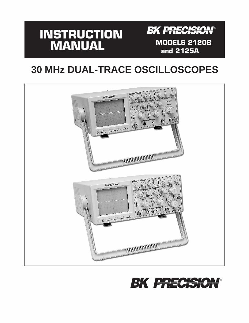
30 MHz DUAL-TRACE OSCILLOSCOPES
BK PRECISION+ ®
INSTRUCTIONMANUAL MODELS 2120B
and 2125A
BK PRECISION+ ®

TEST INSTRUMENT SAFETY
WARNING
Normal use of test equipment exposes you to a certain amount of danger from electrical shock becausetesting must often be performed where exposed high voltage is present. An electrical shock causing10 milliamps of current to pass through the heart will stop most human heartbeats. Voltage as low as 35 voltsdc or ac rms should be considered dangerous and hazardous since it can produce a lethal current undercertain conditions. Higher voltage poses an even greater threat because such voltage can more easilyproduce a lethal current. Your normal work habits should include all accepted practices that will preventcontact with exposed high voltage, and that will steer current away from your heart in case of accidentalcontact with a high voltage. You will significantly reduce the risk factor if you know and observe thefollowing safety precautions:
1. Don’t expose high voltage needlessly in the equipment under test. Remove housings and covers only when necessary.Turn off equipment while making test connections in high-voltage circuits. Discharge high-voltage capacitors afterremoving power.
2. If possible, familiarize yourself with the equipment being tested and the location of its high voltage points. However,remember that high voltage may appear at unexpected points in defective equipment.
3. Use an insulated floor material or a large, insulated floor mat to stand on, and an insulated work surface on which toplace equipment; make certain such surfaces are not damp or wet.
4. Use the time-proven “one hand in the pocket” technique while handling an instrument probe. Be particularly careful toavoid contacting a nearby metal object that could provide a good ground return path.
5. When using a probe, touch only the insulated portion. Never touch the exposed tip portion.
6. When testing ac powered equipment, remember that ac line voltage is usually present on some power input circuits suchas the on-off switch, fuses, power transformer, etc. any time the equipment is connected to an ac outlet, even if theequipment is turned off.
7. Some equipment with a two-wire ac power cord, including some with polarized power plugs, is the “hot chassis” type.This includes most recent television receivers and audio equipment. A plastic or wooden cabinet insulates the chassisto protect the customer. When the cabinet is removed for servicing, a serious shock hazard exists if the chassis is touched.Not only does this present a dangerous shock hazard, but damage to test instruments or the equipment under test mayresult from connecting the ground lead of most test instruments (including this oscilloscope) to a “hot chassis”. To makemeasurements in “hot chassis” equipment, always connect an isolation transformer between the ac outlet and theequipment under test. TheB+K Precision Model TR-110 or 1604A Isolation Transformer, or Model 1653A or 1655AAC Power Supply is suitable for most applications. To be on the safe side, treat all two wire ac powered equipment as“hot chassis” unless you are sure it has an isolated chassis or an earth ground chassis.
8. Never work alone. Someone should be nearby to render aid if necessary. Training in CPR (cardio-pulmonaryresuscitation) first aid is highly recommended.
This symbol on oscilloscope means “refer to instruction manualfor further precautionary information”. This symbol appears in themanual where the corresponding information is given.
Instruction Manual
for
Models 2120Band 2125A
30 MHzDual-Trace Oscilloscopes
©2000 B+K Precision Corp.
+ ®
1031 Segovia Circle, Placentia, CA 92870
BK PRECISION+ ®
TABLE OF CONTENTS
Page Page
TEST INSTRUMENT SAFETY . . . . . . inside front cover
FEATURES . . . . . . . . . . . . . . . . . . . . . . . . . . . . . . . . . . . . 3
SPECIFICATIONS . . . . . . . . . . . . . . . . . . . . . . . . . . . . . . 5
CONTROLS AND INDICATORS . . . . . . . . . . . . . . . . . . 7
General Function Controls . . . . . . . . . . . . . . . . . . . . . . 7
Vertical Controls. . . . . . . . . . . . . . . . . . . . . . . . . . . . . . 7
Horizontal Controls . . . . . . . . . . . . . . . . . . . . . . . . . . . 9
Triggering Controls . . . . . . . . . . . . . . . . . . . . . . . . . . . 9
Rear Panel Controls . . . . . . . . . . . . . . . . . . . . . . . . . . 10
OPERATING INSTRUCTIONS. . . . . . . . . . . . . . . . . . . 11
Safety Precautions . . . . . . . . . . . . . . . . . . . . . . . . . . . 11
Equipment Protection Precautions . . . . . . . . . . . . . . . 11
Operating Tips . . . . . . . . . . . . . . . . . . . . . . . . . . . . . . 12
Initial Starting Procedure . . . . . . . . . . . . . . . . . . . . . . 12
Single Trace Display . . . . . . . . . . . . . . . . . . . . . . . . . 12
Dual Trace Display. . . . . . . . . . . . . . . . . . . . . . . . . . . 12
Triggering . . . . . . . . . . . . . . . . . . . . . . . . . . . . . . . . . . 13
Magnified Sweep Operation . . . . . . . . . . . . . . . . . . . 15
OPERATING INSTRUCTIONS (Continued)
X−Y Operation . . . . . . . . . . . . . . . . . . . . . . . . . . . . . 15
Video Signal Observation . . . . . . . . . . . . . . . . . . . . . 15
Application Guidebook . . . . . . . . . . . . . . . . . . . . . . . 15
Delayed Sweep Operation. . . . . . . . . . . . . . . . . . . . . 15
Component Test Operation . . . . . . . . . . . . . . . . . . . . 16
MAINTENANCE. . . . . . . . . . . . . . . . . . . . . . . . . . . . . . 20
Fuse Replacement . . . . . . . . . . . . . . . . . . . . . . . . . . . 20
Line Voltage Selection. . . . . . . . . . . . . . . . . . . . . . . . 20
Periodic Adjustments. . . . . . . . . . . . . . . . . . . . . . . . . 20
Calibration Check . . . . . . . . . . . . . . . . . . . . . . . . . . . 21
Instrument Repair Service. . . . . . . . . . . . . . . . . . . . . 21
APPENDIX . . . . . . . . . . . . . . . . . . . . . . . . . . . . . . . . . . 22
Important Considerations for Rise Time andFall Time Measurements . . . . . . . . . . . . . . . . . . . . 22
Service Information . . . . . . . . . . . . . . . . . . . . . . . . . . . . 23
Limited Warranty . . . . . . . . . . . . . . . . . . . . . . . . . . . . . . 24
“Guidebook To Oscilloscopes”Availability . . . . . . . . . . . . . . . . . . . . . inside back cover
2
FEATURES
LOW COST, HIGH PERFORMANCEB+K Precision’s entry level oscilloscopes, Models 2120B
and 2125A, are economically priced to equal the competi-tion, but offer higher performance than the competition. Forexample, most competitor’s entry level oscilloscopes have a20 MHz bandwidth, while B+K Precision’s Models 2120Band 2125A offer a 30 MHz bandwidth. These oscilloscopesare built by and backed by B+K Precision, a company thathas been selling reliable, durable, value priced test instru-ments for over 50 years.
CRT FEATURESRectangular CRT
Rectangular CRT with large 8 x 10 centimeter viewingarea. On Model 2125A, graticule is equipped withvariable scale illumination.
ConvenienceTrace rotation electrically adjustable from front panel.0%, 10%, 90%, and 100% markers for rise time meas-urements.
DUAL TRACE FEATURESDual Trace
Models 2120B and 2125A each have two vertical inputchannels for displaying two waveforms simultane-ously. Selectable single trace (either CH 1 or CH 2) ordual trace. Alternate or chop sweep selectable at allsweep rates.
Sum and Difference CapabilityPermits algebraic addition or subtraction of channel 1and channel 2 waveforms, displayed as a single trace.Useful for differential voltage and distortion measure-ments.
HIGH FREQUENCY FEATURESWide Bandwidth
Conservatively-rated−3 dB bandwidth is dc to 30MHz.
Fast Rise TimeRise time is less than 12 ns.
Fast SweepMaximum sweep speed of 10 ns/div (with X10 MAG)assures high frequencies and short-duration pulses aredisplayed with high resolution.
VERTICAL FEATURESHigh Sensitivity
5 mV/div sensitivity for full bandwidth. High-sen-sitivity 1 mV/div and 2 mV/div using PULL X5 gaincontrol.
Calibrated Voltage MeasurementsAccurate voltage measurements (±3%) on 10 cali-brated ranges from 5 mV/div to 5 V/ div. Vertical gainfully adjustable between calibrated ranges.
SWEEP FEATURESCalibrated Time Measurements
Accurate (±3%) time measurements. The main sweephas 23 calibrated ranges from 2 S/div to 0.1µS/div.The delayed sweep on the Model 2125A has 23 cali-brated ranges from 2 S/div to 0.1µS/div. Sweep timeis fully adjustable between calibrated ranges.
X10 Sweep MagnificationAllows closer examination of waveforms, increasesmaximum sweep rate to 10 nS/div.
DUAL TIME BASE FEATURES (Model 2125A)Dual Sweep Generators
Main sweep gives normal waveform display, delayedsweep may be operated at faster sweep speed to expanda portion of the waveform.
Four Sweep ModesChoice of main sweep only, delayed sweep only,main sweep and delayed sweep sharing the trace(percentage of main/delayed sweep adjustable), orX−Y.
Adjustable Start Of Delayed SweepDELAY TIME POSition control allows adjustment ofdelayed sweep starting point.
TRIGGERING FEATURESTwo Trigger Modes
Selectable normal (triggered) or automatic sweepmodes.
Triggered SweepSweep remains at rest unless adequate trigger signal isapplied. Fully adjustable trigger level and (+) or (−)slope.
3
AUTO SweepSelectable AUTO sweep provides sweep without trig-ger input, automatically reverts to triggered sweepoperation when adequate trigger is applied.
Five Trigger SourcesFive trigger source selections, including CH 1, CH 2,alternate, EXT, and LINE.
Video SyncFrame (TV V) or Line (TV H) triggering selectable forobserving composite video waveforms. TV-H positioncan also be used as low frequency reject and TV-Vposition can be used as high frequency reject.
Variable HoldoffTrigger inhibit period after end of sweep adjustable.Permits stable observation of complex pulse trains.
OTHER FEATURESX−Y Operation
Channel 1 can be applied as horizontal deflection(X-axis) while channel 2 provides vertical deflection(Y-axis).
Built-in Probe Adjust Square WaveA 2 V p-p, 1 kHz square wave generator permits probecompensation adjustment.
Component Test Function (Model 2125A)Built-in X−Y type component tester applies fixed levelac signal to components for display of signature onCRT.
Channel 2 (Y) Output (Model 2125A)A buffered 50Ω output of the channel 2 signal isavailable at the rear panel for driving a frequencycounter or other instruments. The output is 50 mV/div(nominal) into 50Ω.
Z-Axis Input (Model 2125A)Rear panel Z-Axis input allows intensity modulation.
Supplied With Two Probes
FEATURES
4
SPECIFICATIONS
CRT:Type: 6-inch rectangular with integral graticule,
P31 phosphor.
Display Area: 8 x 10 div (1 div = 1 cm).
Accelerating Voltage:2 kV.
Phosphor:P31.
Trace Rotation: Electrical, front panel adjustable.
Scale Illumination: Continuously variable (Model 2125A).
Beam Finder (Model 2125A).
VERTICAL AMPLIFIERS (CH 1 and CH 2)Sensitivity: 5 mV/div to 5 V/div, 1 mv/div to 1 V/div at
X5 MAG.
Attenuator: 10 calibrated steps in 1-2-5 sequence. Verniercontrol provides fully adjustable sensitivity betweensteps; range 1/1 to at least 1/3.
Accuracy: ±3%, 5 mV to 5 V/div; 5%, at X5 MAG.
Input Resistance: 1 MΩ ±2%.
Input Capacitance: 25 pF ±10 pF.
Frequency Response:5 mV/div to 5 V/div:
DC to 30 MHz (−3 dB).
X5 MAG:DC to 10 MHz (−3 dB).
Rise Time:12 nS; 35 nS at X5 MAG.
Overshoot:Less than 5%.
Operating Modes:CH 1: CH 1, single trace.
CH 2: CH 2, single trace.
DUAL: CH 1 and CH 2, dual trace.Alternate or Chop selectable atany sweep rate.
ADD: Algebraic sum of CH 1 + CH 2.
Chop Frequency:Approximately 500 kHz.
Polarity Reversal: CH 2 invert.
Maximum Input Voltage: 400 V (dc + ac peak).
HORIZONTAL AMPLIFIER(Input through channel 1 input)
X−Y mode:CH 1 = X axis.CH 2 = Y axis.
Sensitivity: Same as vertical channel 2.
Input Impedance: Same as vertical channel 2.
Frequency Response:DC to 1 MHz (−3 dB).
X-Y Phase Difference:3° or less at 50 kHz.
Maximum Input Voltage: Same as vertical channel 1.
SWEEP SYSTEMOperating Modes:
Model 2125A: Main, Mix (both main and delayedsweep displayed), Delay (only delayed sweepdisplayed), X−Y.
Model 2120B: Main only.
Main Time Base:0.1µS/div to 2.0 S/div in 1-2-5sequence, 23 steps. Vernier control provides fullyadjustable sweep time between steps.
Delayed Time Base (Model 2125A only):0.1µS/div to2.0 S/div in 1-2-5 sequence, 23 steps.
Accuracy: ±3%, except ±6% on 0.2 S/div and ±20% on0.1µS/div.
Sweep Magnification:X10 ±10%.
Holdoff: Continuously adjustable for main time base fromNORM to 5 times normal.
Delay Time Position:Control sets percentage of displaythat is devoted to main and delayed sweep.
Delay Jitter: 1/10,000 of full scale sweep time.
TRIGGERINGTrigger Modes:
AUTO (free run), NORM, TV-V, TV-H.
Trigger Source:CH 1, CH 2, Alternate, EXT, LINE.
Slope:(+) or (–).
5
Trigger Coupling:AUTO: Sweep free-runs in absence of
suitable trigger signal.
NORM: Sweep triggered only by adequatetrigger signal.
TV-V: Video vertical sync pulses areselected. Also usable for highfrequency reject.
TV-H: Video horizontal sync pulses areselected. Also usable for lowfrequency reject.
Trigger Sensitivity:Auto: 1.5 div (internal)
≥0.5 Vp-p (external)100 Hz – 40 MHz (2125A)100 Hz – 30 MHz (2120B)
Norm: 1.5 div (internal)≥0.5 Vp-p (external)100 Hz – 40 MHz (2125A)DC – 30 MHz (2120B)
TV-V: 1.0 div (internal)≥0.5 Vp-p (external)DC – 1 kHz (2125A)20 Hz – 1 kHz (2120B)
TV-H: 1.0 div (internal)≥0.5 Vp-p (external)1 kHz– 100 kHz
Maximum External Trigger Voltage: 300 V (dc + acpeak).
COMPONENT TESTER (Model 2125A)Components Tested:Resistors, capacitors, inductors, and
semiconductors.
Test Voltage:6 V rms maximum (open).
Test Current: 11 mA maximum (shorted).
Test Frequency:Line frequency (60 Hz in USA).
OTHER SPECIFICATIONSCal/Probe Compensation Voltage:2 V p-p±3% square
wave, 1 kHz nominal.
CH 2 (Y) Output (Model 2125A):Output Voltage: 50 mV/div (nominal into 50 ohm
load).
Output Impedance: Approximately 50 ohms.
Frequency Response:20 Hz to 30 MHz,−3 dB.
Intensity Modulation (Model 2125A)
Input Signal: TTL level, intensity increasing withmore positive levels, decreased intensity with morenegative levels.
Input Impedance: Approximately 50 kΩ.
Usable Frequency Range:DC to 5 MHz.
Maximum Input Voltage: 30 V (dc + ac peak).
Power Requirements:100–130 VAC or 200–260 VAC,50/60 Hz, 38 watts.
Dimensions (H3 W 3 D):5.2″ 3 12.8″ 3 15.7″(1323 3243 398 mm).
Weight: 16.8 lbs (7.6 kg).
Environment:Within Specified Accuracy: +10° to +35° C, 10–80%
relative humidity.
Full Operation: 0° to +50° C, 10–80% relativehumidity.
Storage:−30° to +70° C, 10–90% relative humidity.
ACCESORIES SUPPLIED:Two Switchable X1/X10 Probes.
Instruction Manual.AC Line Cord.
SPECIFICATIONS
6
2 61 4
1733
1832 31
30 28 27
26
25
24
34
2322212019
111012
9816
715
1413
5
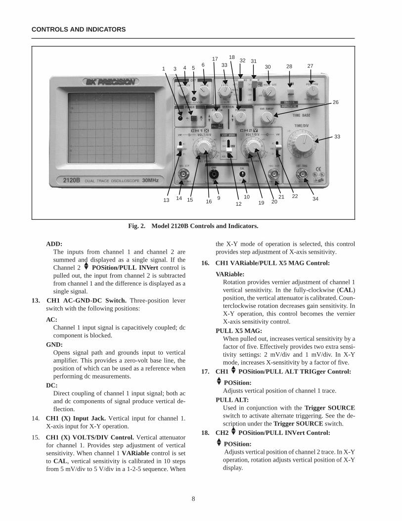
ADD:The inputs from channel 1 and channel 2 aresummed and displayed as a single signal. If theChannel 2 POSition/PULL INVert control ispulled out, the input from channel 2 is subtractedfrom channel 1 and the difference is displayed as asingle signal.
13. CH1 AC-GND-DC Switch. Three-position leverswitch with the following positions:
AC:Channel 1 input signal is capacitively coupled; dccomponent is blocked.
GND:Opens signal path and grounds input to verticalamplifier. This provides a zero-volt base line, theposition of which can be used as a reference whenperforming dc measurements.
DC:Direct coupling of channel 1 input signal; both acand dc components of signal produce vertical de-flection.
14. CH1 (X) Input Jack. Vertical input for channel 1.X-axis input for X-Y operation.
15. CH1 (X) VOLTS/DIV Control. Vertical attenuatorfor channel 1. Provides step adjustment of verticalsensitivity. When channel 1VARiable control is setto CAL , vertical sensitivity is calibrated in 10 stepsfrom 5 mV/div to 5 V/div in a 1-2-5 sequence. When
the X-Y mode of operation is selected, this controlprovides step adjustment of X-axis sensitivity.
16. CH1 VARiable/PULL X5 MAG Control:
VARiable:Rotation provides vernier adjustment of channel 1vertical sensitivity. In the fully-clockwise (CAL )position, the vertical attenuator is calibrated. Coun-terclockwise rotation decreases gain sensitivity. InX-Y operation, this control becomes the vernierX-axis sensitivity control.
PULL X5 MAG:When pulled out, increases vertical sensitivity by afactor of five. Effectively provides two extra sensi-tivity settings: 2 mV/div and 1 mV/div. In X-Ymode, increases X-sensitivity by a factor of five.
17. CH1 POSition/PULL ALT TRIGger Control:
POSition:Adjusts vertical position of channel 1 trace.
PULL ALT:Used in conjunction with theTrigger SOURCEswitch to activate alternate triggering. See the de-scription under theTrigger SOURCE switch.
18. CH2 POSition/PULL INVert Control:
POSition:Adjusts vertical position of channel 2 trace. In X-Yoperation, rotation adjusts vertical position of X-Ydisplay.
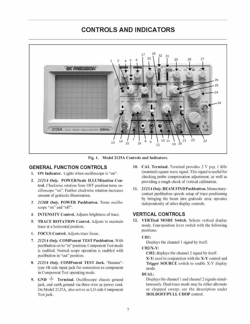
CONTROLS AND INDICATORS
Fig. 2. Model 2120B Controls and Indicators.
8
36
1 4
1733
1832 31
30 28 27
26
33
3422212019
1012
916151413
5
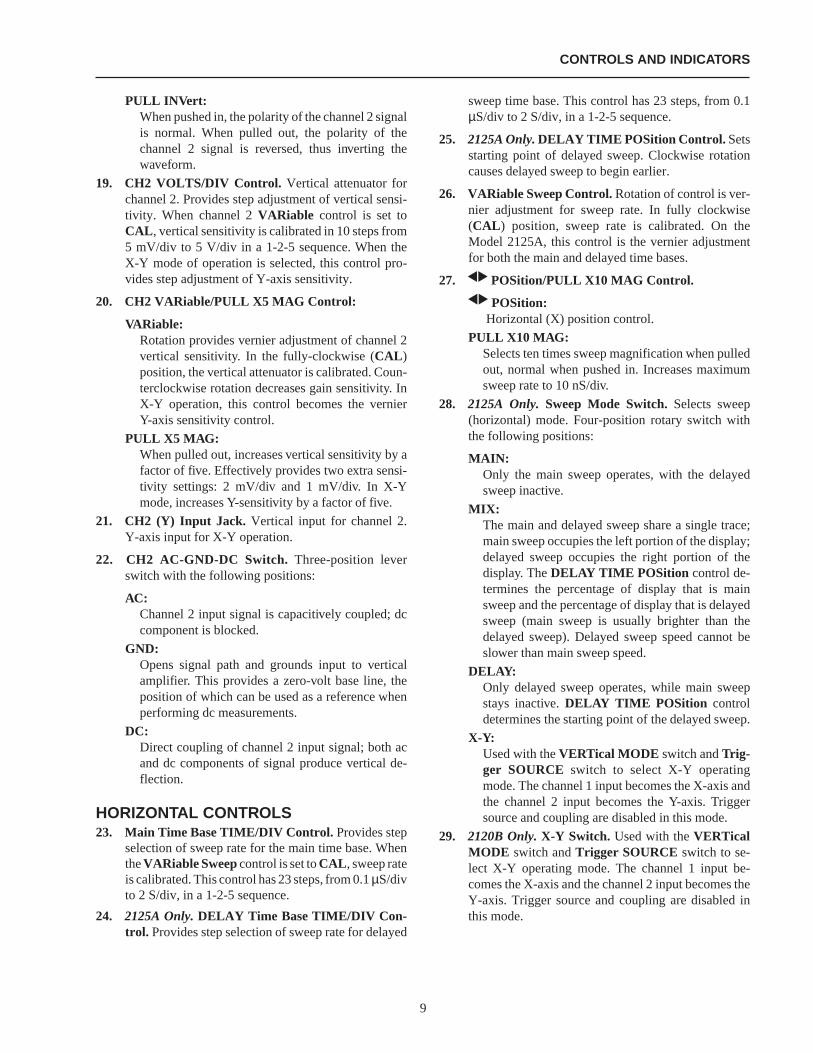
PULL INVert:When pushed in, the polarity of the channel 2 signalis normal. When pulled out, the polarity of thechannel 2 signal is reversed, thus inverting thewaveform.
19. CH2 VOLTS/DIV Control. Vertical attenuator forchannel 2. Provides step adjustment of vertical sensi-tivity. When channel 2VARiable control is set toCAL , vertical sensitivity is calibrated in 10 steps from5 mV/div to 5 V/div in a 1-2-5 sequence. When theX-Y mode of operation is selected, this control pro-vides step adjustment of Y-axis sensitivity.
20. CH2 VARiable/PULL X5 MAG Control:
VARiable:Rotation provides vernier adjustment of channel 2vertical sensitivity. In the fully-clockwise (CAL )position, the vertical attenuator is calibrated. Coun-terclockwise rotation decreases gain sensitivity. InX-Y operation, this control becomes the vernierY-axis sensitivity control.
PULL X5 MAG:When pulled out, increases vertical sensitivity by afactor of five. Effectively provides two extra sensi-tivity settings: 2 mV/div and 1 mV/div. In X-Ymode, increases Y-sensitivity by a factor of five.
21. CH2 (Y) Input Jack. Vertical input for channel 2.Y-axis input for X-Y operation.
22. CH2 AC-GND-DC Switch. Three-position leverswitch with the following positions:
AC:Channel 2 input signal is capacitively coupled; dccomponent is blocked.
GND:Opens signal path and grounds input to verticalamplifier. This provides a zero-volt base line, theposition of which can be used as a reference whenperforming dc measurements.
DC:Direct coupling of channel 2 input signal; both acand dc components of signal produce vertical de-flection.
HORIZONTAL CONTROLS23. Main Time Base TIME/DIV Control. Provides step
selection of sweep rate for the main time base. WhentheVARiable Sweepcontrol is set toCAL , sweep rateis calibrated. This control has 23 steps, from 0.1µS/divto 2 S/div, in a 1-2-5 sequence.
24. 2125A Only.DELAY Time Base TIME/DIV Con-trol. Provides step selection of sweep rate for delayed
sweep time base. This control has 23 steps, from 0.1µS/div to 2 S/div, in a 1-2-5 sequence.
25. 2125A Only.DELAY TIME POSition Control. Setsstarting point of delayed sweep. Clockwise rotationcauses delayed sweep to begin earlier.
26. VARiable Sweep Control.Rotation of control is ver-nier adjustment for sweep rate. In fully clockwise(CAL ) position, sweep rate is calibrated. On theModel 2125A, this control is the vernier adjustmentfor both the main and delayed time bases.
27. POSition/PULL X10 MAG Control.
POSition:Horizontal (X) position control.
PULL X10 MAG:Selects ten times sweep magnification when pulledout, normal when pushed in. Increases maximumsweep rate to 10 nS/div.
28. 2125A Only. Sweep Mode Switch.Selects sweep(horizontal) mode. Four-position rotary switch withthe following positions:
MAIN:Only the main sweep operates, with the delayedsweep inactive.
MIX:The main and delayed sweep share a single trace;main sweep occupies the left portion of the display;delayed sweep occupies the right portion of thedisplay. TheDELAY TIME POSition control de-termines the percentage of display that is mainsweep and the percentage of display that is delayedsweep (main sweep is usually brighter than thedelayed sweep). Delayed sweep speed cannot beslower than main sweep speed.
DELAY:Only delayed sweep operates, while main sweepstays inactive.DELAY TIME POSition controldetermines the starting point of the delayed sweep.
X-Y:Used with theVERTical MODE switch andTrig-ger SOURCE switch to select X-Y operatingmode. The channel 1 input becomes the X-axis andthe channel 2 input becomes the Y-axis. Triggersource and coupling are disabled in this mode.
29. 2120B Only.X-Y Switch. Used with theVERTicalMODE switch andTrigger SOURCE switch to se-lect X-Y operating mode. The channel 1 input be-comes the X-axis and the channel 2 input becomes theY-axis. Trigger source and coupling are disabled inthis mode.
CONTROLS AND INDICATORS
9
TRIGGERING CONTROLS30. HOLDOFF/PULL CHOP Control.
HOLDOFF:Rotation adjusts holdoff time (trigger inhibit periodbeyond sweep duration). When control is rotatedfully counterclockwise, the holdoff period isMIN-inum (normal). The holdoff period increases pro-gressively with clockwise rotation.
PULL CHOP:When this switch is pulled out in the dual-tracemode, the channel 1 and channel 2 sweeps arechopped and displayed simultaneously (normallyused at slower sweep speeds). When it is pushed in,the two sweeps are alternately displayed, one afterthe other (normally used at higher sweep speeds).
31. Trigger SOURCE Switch. Selects source of sweeptrigger. Four-position lever switch with the followingpositions:
CH1/X-Y/ALTCH1:
Causes the channel 1 input signal to become thesweep trigger, regardless of theVERTicalMODE switch setting.
X-Y:Used with two other switches to enable the X-Ymode — see the Operating Instructions under“XY Operation”.
ALT:Used with the channel 1 POSition/PULLALTernate TRIGger control to enable alternatetriggering. Alternate triggering, used in dual-trace mode, permits each waveform viewed tobecome its own trigger source.
CH2:The channel 2 signal becomes the sweep trigger,regardless of theVERTical MODE switch setting.
LINE:Signal derived from input line voltage (50/60 Hz)becomes trigger.
EXT:Signal from EXTernal TRIGger jack becomessweep trigger.
32. Trigger COUPLING Switch. Selects trigger cou-pling. Four-position lever switch with the followingpositions:
AUTO:Selects automatic triggering mode. In this mode, theoscilloscope generates sweep (free runs) in absenceof an adequate trigger; it automatically reverts totriggered sweep operation when an adequate triggersignal is present. On the Model 2125A, automatictriggering is applicable to both the main sweep anddelayed sweep.
NORM:Selects normal triggered sweep operation. A sweepis generated only when an adequate trigger signal ispresent.
TV-V:Used for triggering from television vertical syncpulses. Also serves as lo-pass/dc (high frequencyreject) trigger coupling.
TV-H:Used for triggering from television horizontal syncpulses. Also serves as hi-pass (low frequency reject)trigger coupling.
33. TRIGger LEVEL/PULL (-) SLOPE Control.
TRIGger LEVEL:Trigger level adjustment; determines the point onthe triggering waveform where the sweep is trig-gered. Rotation in the (-) direction (counterclock-wise) selects more negative triggering point;rotation in the (+) direction (clockwise) selectsmore positive triggering point.
PULL (—) SLOPE:Two-position push-pull switch. The “in” positionselects a positive-going slope and the “out” positionselects a negative-going slope as triggering point formain sweep.
34. EXTernal TRIGger Jack. External trigger input forsingle- and dual-trace operation.
REAR PANEL CONTROLS (not shown)35. Fuse Holder/Line Voltage Selector.Contains fuse
and selects line voltage.
36. Power Cord Receptacle.
37. 2125A Only.CH 2 (Y) SIGNAL OUTPUT Jack.Output terminal where sample of channel 2 signal isavailable. Amplitude of output is nominally 50 mV perdivision of vertical deflection seen on CRT whenterminated into 50Ω. Output impedance is 50Ω.
38. 2125A Only.Z-Axis Input Jack. Input jack for inten-sity modulation of CRT electron beam. TTL compat-ible (5 V p-p sensitivity). Positive levels increaseintensity.
39. Handle/Tilt Stand.
40. Feet/Cord Wrap.
CONTROLS AND INDICATORS
10
OPERATING INSTRUCTIONS
NOTEAll operating instructions in this chapterapply equally to both Models 2125A and2120B, except for the sections on “DelayedSweep Operation” and “Component Test”,which apply only to the Model 2125A.Other differences are noted when nec-essary.
SAFETY PRECAUTIONS
WARNING
The following precautions must be ob-served to help prevent electric shock.
1. When the oscilloscope is used to make measurementsin equipment that contains high voltage, there is al-ways a certain amount of danger from electrical shock.The person using the oscilloscope in such conditionsshould be a qualified electronics technician or other-wise trained and qualified to work in such circum-stances. Observe the TEST INSTRUMENT SAFETYrecommendations listed on the inside front cover ofthis manual.
2. Do not operate this oscilloscope with the case removedunless you are a qualified service technician. Highvoltage up to 2100 volts is present when the unit isoperating with the case removed.
3. The ground wire of the 3-wire ac power plug placesthe chassis and housing of the oscilloscope at earthground. Use only a 3-wire outlet, and do not attemptto defeat the ground wire connection or float the oscil-loscope; to do so may pose a great safety hazard.
4. Special precautions are required to measure or observeline voltage waveforms with any oscilloscope. Use thefollowing procedure:
a. Do not connect the ground clip of the probe toeither side of the line. The clip is already at earthground and touching it to the hot side of the linemay “weld” or “disintegrate” the probe tip andcause possible injury, plus possible damage to thescope or probe.
b. Insert the probe tip into one side of the line voltagereceptacle, then the other. One side of the recepta-cle should be “hot” and produce the waveform. Theother side of the receptacle is the ac return and nowaveform should result.
EQUIPMENT PROTECTIONPRECAUTIONS
The following precautions will help avoiddamage to the oscilloscope.
1. Never allow a small spot of high brilliance to remainstationary on the screen for more than a few seconds.The screen may become permanently burned. A spotwill occur when the scope is set up for X−Y operationand no signal is applied. Either reduce the intensity sothe spot is barely visible, apply signal, or switch backto normal sweep operation. It is also advisable to uselow intensity with AUTO triggering and no signalapplied for long periods. A high intensity trace at thesame position could cause a line to become perma-nently burned onto the screen.
2. Do not obstruct the ventilating holes in the case, as thiswill increase the scope’s internal temperature.
3. Excessive voltage applied to the input jacks may dam-age the oscilloscope. The maximum ratings of theinputs are as follows:
CH 1 and CH 2:400 V dc + ac peak.
EXT TRIG:300 V dc + ac peak.
Z-AXIS INPUT (Model 2125A):30 V ( dc and ac peak).
4. Always connect a cable from the ground terminal ofthe oscilloscope to the chassis of the equipment undertest. Without this precaution, the entire current for theequipment under test may be drawn through the probeclip leads under certain circumstances. Such condi-tions could also pose a safety hazard, which the groundcable will prevent.
5. The probe ground clips are at oscilloscope and earthground and should be connected only to the earthground or isolated common of the equipment undertest. To measure with respect to any point other thanthe common, use CH 2 – CH 1 subtract operation(ADD mode andINV 1 ), with the channel 2 probe tothe point of measurement and the channel 1 probe tothe point of reference. Use this method even if thereference point is a dc voltage with no signal.
11
OPERATING TIPSThe following recommendations will help obtain the best
performance from the oscilloscope.
1. Always use the probe ground clips for best results,attached to a circuit ground point near the point ofmeasurement. Do not rely solely on an external groundwire in lieu of the probe ground clips as undesiredsignals may be introduced.
2. Avoid the following operating conditions:
a. Direct sunlight.
b. High temperature and humidity.
c. Mechanical vibration.
d. Electrical noise and strong magnetic fields, such asnear large motors, power supplies, transformers,etc.
3. Occasionally check trace rotation, probe compensa-tion, and calibration accuracy of the oscilloscope usingthe procedures found in the MAINTENANCE sectionof this manual.
4. Terminate the output of a signal generator into itscharacteristic impedance to minimize ringing, espe-cially if the signal has fast edges such as square wavesor pulses. For example, the typical 50Ω output of asquare wave generator should be terminated into anexternal 50Ω terminating load and connected to theoscilloscope with 50Ω coaxial cable.
5. Probe compensation adjustment matches the probe tothe input of the scope. For best results, compensationshould be adjusted initially, then the same probe al-ways used with the same channel. Probe compensationshould be readjusted when a probe from a differentoscilloscope is used.
INITIAL STARTING PROCEDUREUntil you familiarize yourself with the use of all controls,
the settings given here can be used as a reference point toobtain a trace on the CRT in preparation for waveformobservation.
1. Set these controls as follows:
On both models:VERTical MODE to CH1.CH1 AC/GND/DC to GND.Trigger COUPLING toAUTO.Trigger SOURCE to CH1.All POSition controls andINTENSITY control cen-tered (pointers facing up).Main Time Basecontrol to1 mS/div.On the Model 2125A:Sweep Modeswitch toMAIN .
2. Press the redPOWER pushbutton (Model 2120B), orrotate thePOWER control clockwise away from“OFF” (Model 2125A).
3. A trace should appear on the CRT. Adjust the tracebrightness with theINTENSITY control, and thetrace sharpness with theFOCUScontrol.
NOTEOn the Model 2125A, you can use theBEAM FINDER pushbutton to locate atrace that has been moved off the screen bythePOSition controls. When the button ispushed, a compressed version of the traceis brought into view which indicates thelocation of the trace.
SINGLE TRACE DISPLAYEither channel 1 or channel 2 may be used for single-trace
operation. To observe a waveform on channel 1:
1. Perform the steps of the “Initial Starting Procedure”.
2. Connect the probe to theCH 1 (X) input jack.
3. Connect the probe ground clip to the chassis or com-mon of the equipment under test. Connect the probetip to the point of measurement.
4. Move theCH1 AC/GND/DC switch out of theGNDposition to eitherDC or AC.
5. If no waveforms appear, increase the sensitivity byturning theCH 1 VOLTS/DIV control clockwise to aposition that gives 2 to 6 divisions vertical deflection.
6. Position the waveform vertically as desired using theCH1 POSition control.
7. The display on the CRT may be unsynchronized. Referto the “Triggering” paragraphs in this section for pro-cedures on setting triggering and sweep time controlsto obtain a stable display showing the desired numberof waveforms.
DUAL TRACE DISPLAYIn observing simultaneous waveforms on channel 1 and
2, the waveforms are usually related in frequency, or one ofthe waveforms is synchronized to the other, although thebasic frequencies are different. To observe two such relatedwaveforms simultaneously, perform the following:
1. Connect probes to both theCH 1 (X) andCH 2 (Y)input jacks.
2. Connect the ground clips of the probes to the chassisor common of the equipment under test. Connect thetips of the probes to the two points in the circuit wherewaveforms are to be measured.
OPERATING INSTRUCTIONS
12
3. To view both waveforms simultaneously, set theVERTical MODE switch toDUAL and select eitherALT (alternate) orCHOP with the PULL CHOPswitch.
4. In the ALT sweep mode (PULL CHOP switchpushed in), one sweep displays the channel 1 signaland the next sweep displays the channel 2 signal in analternating sequence. Alternate sweep is normallyused for viewing high-frequency or high-speed wave-forms at sweep times of 1 ms/div and faster, but maybe selected at any sweep time.
5. In the CHOP sweep mode (PULL CHOP switchpulled out), the sweep is chopped (switched) betweenchannel 1 and channel 2. UsingCHOP, one channeldoes not have to “wait” for a complete swept displayof the other channel. Therefore, portions of both chan-nel’s waveforms are displayed with the phase relation-ship between the two waveforms unaltered. Chopsweep is normally used for low-frequency or low-speed waveforms at sweep times of 1 ms/div andslower; or where the phase relationship between chan-nel 1 and channel 2 requires measurement.
If chop sweep is used at sweep times of 0.2 ms/div andfaster, the chop rate becomes a significant portion ofthe sweep and may become visible in the displayedwaveform. However, you may select chop sweep atany sweep time for special applications.
6. Adjust the channel 1 and 2 POSition controls toplace the channel 1 trace above the channel 2 trace.
7. Set theCH 1 and CH 2 VOLTS/DIV controls to aposition that gives 2 to 3 divisions of vertical deflec-tion for each trace. If the display on the screen isunsynchronized, refer to the “Triggering” paragraphsin this section of the manual for procedures for settingtriggering and sweep time controls to obtain a stabledisplay showing the desired number of waveforms.
8. When theVERTical MODE switch is set toADD, thealgebraic sum of CH 1 + CH 2 is displayed as a singletrace. When thePULL INV switch is pulled out, thealgebraic difference of CH 1 – CH 2 is displayed.
9. If two waveforms have no phase or frequency relation-ship, there is seldom reason to observe both wave-forms simultaneously. However, these oscilloscopesdo permit the simultaneous viewing of two such unre-lated waveforms, using alternate triggering. Refer tothe paragraphs on “Triggering - Trigger SOURCESwitch”, for details on alternate triggering.
TRIGGERINGThe Models 2125A and 2120B Oscilloscopes provide
versatility in sync triggering for ability to obtain a stable,jitter-free display in single-trace, or dual-trace operation.The proper settings depend upon the type of waveformsbeing observed and the type of measurement desired. Anexplanation of the various controls which affect synchroni-zation is given to help you select the proper setting over awide range of conditions.
Trigger COUPLING Switch1. In theAUTO position, automatic sweep operation is
selected. In automatic sweep operation, the sweepgenerator free-runs to generate a sweep without atrigger signal. However, it automatically switches totriggered sweep operation if an acceptable triggersource signal is present. TheAUTO position is handywhen first setting up the scope to observe a waveform;it provides sweep for waveform observation until othercontrols can be properly set. Once the controls are set,operation is often switched back to the normal trigger-ing mode, since it is more sensitive. Automatic sweepmust be used for dc measurements and signals of suchlow amplitude that they will not trigger the sweep.
2. TheNORM position provides normal triggeredsweep operation. The sweep remains at rest until theselected trigger source signal crosses the thresholdlevel set by theTRIG LEVEL control. The triggercauses one sweep to be generated, after which thesweep again remains at rest until triggered. In thenormal triggering mode, there will be no trace unlessan adequate trigger signal is present. In theALTVERTICAL MODE of dual trace operation with theSOURCE switch also set toALT , there will be notrace unless both channel 1 and channel 2 signals areadequate for triggering. Typically, signals that pro-duce even one division of vertical deflection are ade-quate for normal triggered sweep operation.
3. The TV H and TV V positions are primarily forviewing composite video waveforms. Horizontal syncpulses are selected as trigger when the triggerCOU-PLING switch is set to theTV H position, and verticalsync pulses are selected as trigger when the triggerCOUPLING switch is set to theTV V position. TheTV H andTV V positions may also be used as lowfrequency reject and high frequency reject coupling,respectively. Additional procedures for observing videowaveforms are given later in this section of the manual.
OPERATING INSTRUCTIONS
13
Trigger SOURCE SwitchThe triggerSOURCE switch (CH 1, CH 2, etc.) selects
the signal to be used as the sync trigger.
1. If the SOURCE switch is set toCH 1 (or CH 2) thechannel 1 (or channel 2) signal becomes the triggersource regardless of theVERTICAL MODE selec-tion.CH 1, orCH 2 are often used as the trigger sourcefor phase or timing comparison measurements.
2. By setting theSOURCE switch to ALT (same asCH1) andPULL ALT TRIG pulled, alternating trig-gering mode is activated. In this mode, the triggersource alternates betweenCH 1 andCH 2 with eachsweep. This is convenient for checking amplitudes,waveshape, or waveform period measurements, andeven permits simultaneous observation of two wave-forms which are not related in frequency or period.However, this setting is not suitable for phase or timingcomparison measurements. For such measurements,both traces must be triggered by the same sync signal.Alternate triggering can only be used in dual-tracemode (VERT MODE set toDUAL ), and with alter-nate sweep only (PULL CHOP not engaged).
3. In theLINE position, triggering is derived from theinput line voltage (50/60 Hz) and the triggerSOURCEswitch is disabled. This is useful for meas-urements that are related to line frequency.
4. In theEXT position, the signal applied to theEXTTRIG jack becomes the trigger source. This signalmust have a timing relationship to the displayed wave-forms for a synchronized display.
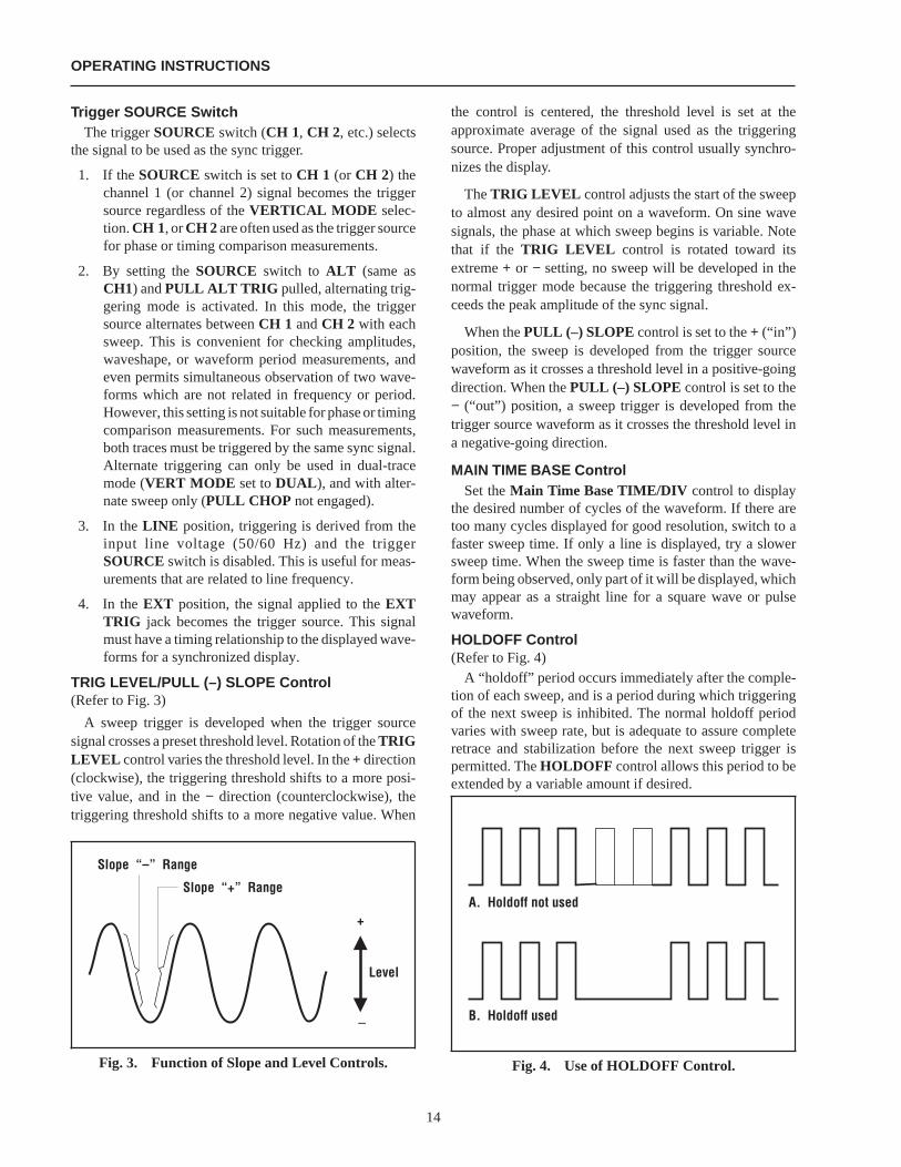
TRIG LEVEL/PULL (–) SLOPE Control(Refer to Fig. 3)
A sweep trigger is developed when the trigger sourcesignal crosses a preset threshold level. Rotation of theTRIGLEVEL control varies the threshold level. In the+ direction(clockwise), the triggering threshold shifts to a more posi-tive value, and in the− direction (counterclockwise), thetriggering threshold shifts to a more negative value. When
the control is centered, the threshold level is set at theapproximate average of the signal used as the triggeringsource. Proper adjustment of this control usually synchro-nizes the display.
TheTRIG LEVEL control adjusts the start of the sweepto almost any desired point on a waveform. On sine wavesignals, the phase at which sweep begins is variable. Notethat if the TRIG LEVEL control is rotated toward itsextreme+ or − setting, no sweep will be developed in thenormal trigger mode because the triggering threshold ex-ceeds the peak amplitude of the sync signal.
When thePULL (–) SLOPE control is set to the+ (“in”)position, the sweep is developed from the trigger sourcewaveform as it crosses a threshold level in a positive-goingdirection. When thePULL (–) SLOPE control is set to the− (“out”) position, a sweep trigger is developed from thetrigger source waveform as it crosses the threshold level ina negative-going direction.
MAIN TIME BASE ControlSet theMain Time Base TIME/DIV control to display
the desired number of cycles of the waveform. If there aretoo many cycles displayed for good resolution, switch to afaster sweep time. If only a line is displayed, try a slowersweep time. When the sweep time is faster than the wave-form being observed, only part of it will be displayed, whichmay appear as a straight line for a square wave or pulsewaveform.
HOLDOFF Control(Refer to Fig. 4)
A “holdoff” period occurs immediately after the comple-tion of each sweep, and is a period during which triggeringof the next sweep is inhibited. The normal holdoff periodvaries with sweep rate, but is adequate to assure completeretrace and stabilization before the next sweep trigger ispermitted. TheHOLDOFF control allows this period to beextended by a variable amount if desired.
Slope “–” Range
Slope “+” Range
Level
+
–
Fig. 3. Function of Slope and Level Controls.
OPERATING INSTRUCTIONS
A. Holdoff not used
B. Holdoff used
Fig. 4. Use of HOLDOFF Control.
14
This control is usually set to theMIN position (fullycounterclockwise) because no additional holdoff period isnecessary. TheHOLDOFF control is useful when a com-plex series of pulses appear periodically such as in Fig. 4B.Improper sync may produce a double image as in Fig. 4A.Such a display could be synchronized with theVARSWEEPcontrol, but this is impractical because time meas-urements are then uncalibrated. An alternate method ofsynchronizing the display is with theHOLDOFF control.The sweep speed remains the same, but the triggering of thenext sweep is “held off” for the duration selected by theHOLDOFF control. Turn theHOLDOFF control clock-wise from theMIN position until the sweep starts at thesame point of the waveform each time.
MAGNIFIED SWEEP OPERATIONSince merely shortening the sweep time to magnify a
portion of an observed waveform can result in the desiredportion disappearing off the screen, magnified displayshould be performed using magnified sweep.
Using the POSition control, move the desired portionof waveform to the center of the CRT. Pull out thePULL X10knob to magnify the display ten times. For this type of displaythe sweep time is theMain Time Base TIME/DIV controlsetting divided by 10. Rotation of the POSition control canthen be used to select the desired portion of the waveforms.
X−Y OPERATIONX−Y operation permits the oscilloscope to perform many
measurements not possible with conventional sweep opera-tion. The CRT display becomes an electronic graph of twoinstantaneous voltages. The display may be a direct com-parison of the two voltages such as stereoscope display ofstereo signal outputs. However, theX−Y mode can be usedto graph almost any dynamic characteristic if a transducer isused to change the characteristic (frequency, temperature,velocity, etc.) into a voltage. One common application is fre-quency responsemeasurements,where theYaxiscorrespondstosignal amplitude and the X axis corresponds to frequency.
1. On the Model 2125A, set theSWEEP MODE switchto theX−Y position. On the Model 2120B, depress theX−Y switch. On both models, set theTrigger SourceandVERTical MODE switches toX−Y.
2. In this mode, channel 1 becomes the X axis input andchannel 2 becomes the Y axis input. The X and Ypositions are now adjusted using the POSition andthechannel 2 POSition controls respectively.
3. Adjust the amount of vertical (Y axis) deflection withtheCH 2 VOLTS/DIV andVARIABLE controls.
4. Adjust the amount of horizontal (X axis) deflectionwith the CH 1 VOLTS/DIV andVARIABLE con-trols.
VIDEO SIGNAL OBSERVATIONSetting theCOUPLING switch to theTV-H or TV-V
position permits selection of horizontal or vertical syncpulses for sweep triggering when viewing composite videowaveforms.
When theTV-H mode is selected, horizontal sync pulsesare selected as triggers to permit viewing of horizontal linesof video. A sweep time of about 10µs/div is appropriate fordisplaying lines of video. TheVAR SWEEP control can beset to display the exact number of waveforms desired.
When theTV-V mode is selected, vertical sync pulses areselected as triggers to permit viewing of vertical fields andframes of video. A sweep time of 2 ms/div is appropriate forviewing fields of video and 5 ms/div for complete frames(two interlaced fields) of video.
At most points of measurement, a composite video signalis of the (−) polarity, that is, the sync pulses are negative andthe video is positive. In this case, use(− ) SLOPE. If thewaveform is taken at a circuit point where the video wave-form is inverted, the sync pulses are positive and the videois negative. In this case, use(+) SLOPE.
APPLICATIONS GUIDEBOOKB+K Precision offers a “Guidebook to Oscilloscopes”
which describes numerous applications for this instrumentand important considerations about probes. It includes aglossary of oscilloscope terminology and an understandingof how oscilloscopes operate. It may be downloaded free ofcharge from our Web site, www.bkprecision.com.
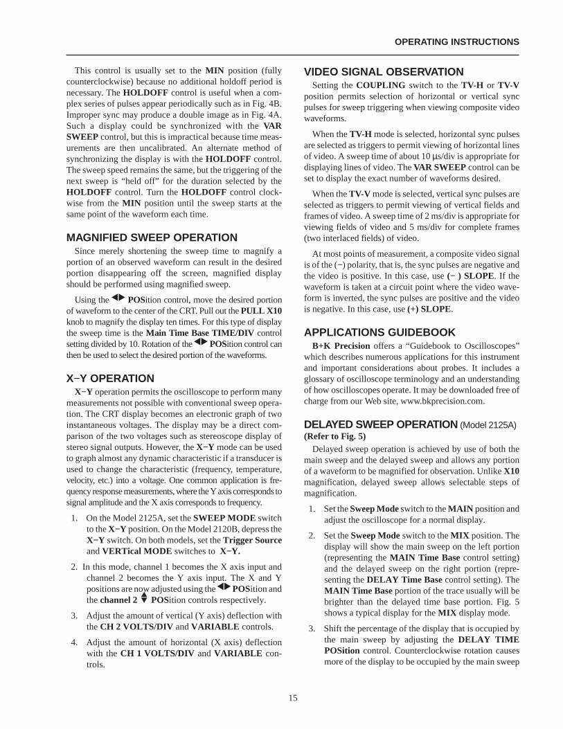
DELAYED SWEEP OPERATION (Model 2125A)(Refer to Fig. 5)
Delayed sweep operation is achieved by use of both themain sweep and the delayed sweep and allows any portionof a waveform to be magnified for observation. UnlikeX10magnification, delayed sweep allows selectable steps ofmagnification.
1. Set theSweep Modeswitch to theMAIN position andadjust the oscilloscope for a normal display.
2. Set theSweep Modeswitch to theMIX position. Thedisplay will show the main sweep on the left portion(representing theMAIN Time Base control setting)and the delayed sweep on the right portion (repre-senting theDELAY Time Base control setting). TheMAIN Time Base portion of the trace usually will bebrighter than the delayed time base portion. Fig. 5shows a typical display for theMIX display mode.
3. Shift the percentage of the display that is occupied bythe main sweep by adjusting theDELAY TIMEPOSition control. Counterclockwise rotation causesmore of the display to be occupied by the main sweep
OPERATING INSTRUCTIONS
15
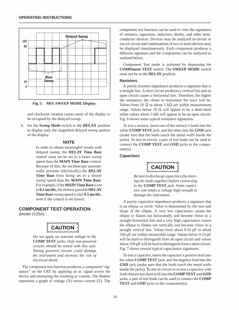
and clockwise rotation causes more of the display tobe occupied by the delayed sweep.
4. Set theSweep Modeswitch to theDELAY positionto display only the magnified delayed sweep portionof the display.
NOTEIn order to obtain meaningful results withdelayed sweep, theDELAY Time Basecontrol must set be set to a faster sweepspeed than theMAIN Time Base control.Because of this, the oscilloscope automat-ically prevents (electrically) theDELAYTime Base from being set to a slowersweep speed than theMAIN Time Base.For example, if theMAIN Time Base is setto0.1 ms/div, the slowest possibleDELAYTime Basesweep speed is also0.1 ms/div,even if the control is set slower.
COMPONENT TEST OPERATION(Model 2125A)
Do not apply an external voltage to theCOMP TEST jacks. Only non-poweredcircuits should be tested with this unit.Testing powered circuits could damagethe instrument and increase the risk ofelectrical shock.
The component test function produces a component “sig-nature” on the CRT by applying an ac signal across thedevice and measuring the resulting ac current. The displayrepresents a graph of voltage (X) versus current (Y). The
component test function can be used to view the signaturesof resistors, capacitors, inductors, diodes, and other semi-conductor devices. Devices may be analyzed in-circuit orout-of-circuit and combinations of two or more devices maybe displayed simultaneously. Each component produces adifferent signature and the components can be analyzed asoutlined below.
Component Test mode is activated by depressing theCOMPonent TEST switch. TheSWEEP MODE switchmust not be in theDELAY position.
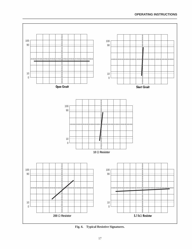
ResistorsA purely resistive impedance produces a signature that is
a straight line. A short circuit produces a vertical line and anopen circuit causes a horizontal line. Therefore, the higherthe resistance, the closer to horizontal the trace will be.Values from 10Ω to about 5 kΩ are within measurementrange. Values below 10Ω will appear to be a dead shortwhile values above 5 kΩ will appear to be an open circuit.Fig. 6 shows some typical resistance signatures.
To test a resistor, insert one of the resistor’s leads into thewhiteCOMP TEST jack, and the other into theGND jack(make sure that the leads touch the metal walls inside thejacks). To test in-circuit, a pair of test leads can be used toconnect theCOMP TEST andGND jacks to the compo-nent(s).
Capacitors
Be sure to discharge capacitors (by short-ing the leads together) before connectingto theCOMP TEST jack. Some capaci-tors can retain a voltage high enough todamage the instrument.
A purely capacitive impedance produces a signature thatis an ellipse or circle. Value is determined by the size andshape of the ellipse. A very low capacitance causes theellipse to flatten out horizontally and become closer to astraight horizontal line and a very high capacitance causesthe ellipse to flatten out vertically and become closer to astraight vertical line. Values from about 0.33µF to about330µF are within measurable range. Values below 0.33µFwill be hard to distinguish from an open circuit and valuesabove 330µF will be hard to distinguish from a short circuit.Fig. 7 shows several typical capacitance signatures.
To test a capacitor, insert the capacitor’s positive lead intothe whiteCOMP TEST jack, and the negative lead into theGND jack (make sure that the leads touch the metal wallsinside the jacks). To test in-circuit or to test a capacitor withleads that are too short to fit into theCOMPTEST andGNDjacks, a pair of test leads can be used to connect theCOMPTEST andGND jacks to the component(s).
OPERATING INSTRUCTIONS
100
90
100
MainSweep
Delayed Sweep
Fig. 5. MIX SWEEP MODE Display.
16
OPERATING INSTRUCTIONS
Fig. 6. Typical Resistive Signatures.
100
90
10
0
Open Circuit
100
90
10
0
Short Circuit
100
90
10
0
200 ResistorΩ
100
90
10
0
5.1 k ResistorΩ
100
90
10
0
10 ResistorΩ
17
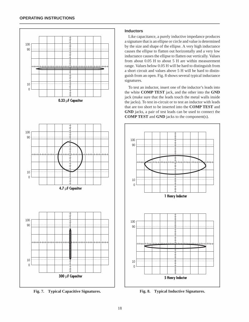
InductorsLike capacitance, a purely inductive impedance produces
a signature that is an ellipse or circle and value is determinedby the size and shape of the ellipse. A very high inductancecauses the ellipse to flatten out horizontally and a very lowinductance causes the ellipse to flatten out vertically. Valuesfrom about 0.05 H to about 5 H are within measurementrange. Values below 0.05 H will be hard to distinguish froma short circuit and values above 5 H will be hard to distin-guish from an open. Fig. 8 shows several typical inductancesignatures.
To test an inductor, insert one of the inductor’s leads intothe whiteCOMP TEST jack, and the other into theGNDjack (make sure that the leads touch the metal walls insidethe jacks). To test in-circuit or to test an inductor with leadsthat are too short to be inserted into theCOMP TEST andGND jacks, a pair of test leads can be used to connect theCOMP TEST andGND jacks to the component(s).
OPERATING INSTRUCTIONS
Fig. 7. Typical Capacitive Signatures. Fig. 8. Typical Inductive Signatures.
100
90
10
0
1 Henry Inductor
100
90
10
0
5 Henry Inductor
100
90
10
0
0.33 F Capacitorµ
100
90
10
0
4.7 F Capacitorµ
100
90
10
0
300 F Capacitorµ
18
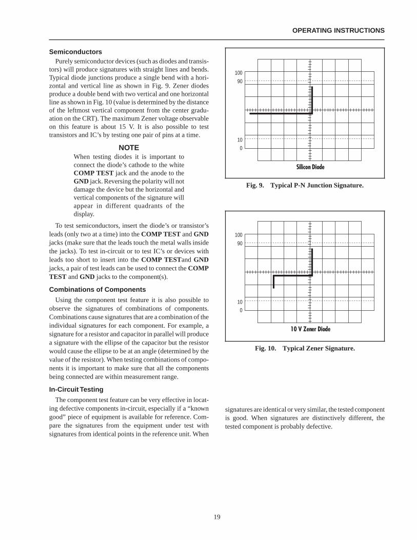
SemiconductorsPurely semiconductor devices (such as diodes and transis-
tors) will produce signatures with straight lines and bends.Typical diode junctions produce a single bend with a hori-zontal and vertical line as shown in Fig. 9. Zener diodesproduce a double bend with two vertical and one horizontalline as shown in Fig. 10 (value is determined by the distanceof the leftmost vertical component from the center gradu-ation on the CRT). The maximum Zener voltage observableon this feature is about 15 V. It is also possible to testtransistors and IC’s by testing one pair of pins at a time.
NOTEWhen testing diodes it is important toconnect the diode’s cathode to the whiteCOMP TEST jack and the anode to theGND jack. Reversing the polarity will notdamage the device but the horizontal andvertical components of the signature willappear in different quadrants of thedisplay.
To test semiconductors, insert the diode’s or transistor’sleads (only two at a time) into theCOMP TEST andGNDjacks (make sure that the leads touch the metal walls insidethe jacks). To test in-circuit or to test IC’s or devices withleads too short to insert into theCOMP TESTandGNDjacks, a pair of test leads can be used to connect theCOMPTEST andGND jacks to the component(s).
Combinations of Components
Using the component test feature it is also possible toobserve the signatures of combinations of components.Combinations cause signatures that are a combination of theindividual signatures for each component. For example, asignature for a resistor and capacitor in parallel will producea signature with the ellipse of the capacitor but the resistorwould cause the ellipse to be at an angle (determined by thevalue of the resistor). When testing combinations of compo-nents it is important to make sure that all the componentsbeing connected are within measurement range.
In-Circuit Testing
The component test feature can be very effective in locat-ing defective components in-circuit, especially if a “knowngood” piece of equipment is available for reference. Com-pare the signatures from the equipment under test withsignatures from identical points in the reference unit. When
signatures are identical or very similar, the tested componentis good. When signatures are distinctively different, thetested component is probably defective.
100
90
10
0
Silicon Diode
Fig. 9. Typical P-N Junction Signature.
100
90
10
0
10 V Zener Diode
Fig. 10. Typical Zener Signature.
OPERATING INSTRUCTIONS
19
MAINTENANCE
WARNING
The following instructions are for use byqualified service personnel only. To avoidelectrical shock, do not perform any serv-icing other than contained in the operat-ing instructions unless you are qualifiedto do so.
High voltage up to 2000 V is present whencovers are removed and the unit is oper-ating. Remember that high voltage maybe retained indefinitely on high voltagecapacitors. Also remember that ac linevoltage is present on line voltage inputcircuits any time the instrument isplugged into an ac outlet, even if turnedoff. Unplug the oscilloscope and dis-charge high voltage capacitors beforeperforming service procedures.
FUSE REPLACEMENTIf the fuse blows, the “ON” indicator will not light and the
oscilloscope will not operate. The fuse should not normallyopen unless a problem has developed in the unit. Try todetermine and correct the cause of the blown fuse, thenreplace only with the correct value fuse. For 110/125 V linevoltage operation, use an 800 mA, 250 V fuse. For 220/240V line voltage operation, use a 600 mA, 250 V fuse. The fuseis located on the rear panel adjacent to the power cordreceptacle.
Remove the fuseholder assembly as follows:
1. Unplug the power cord from rear of scope.
2. Insert a small screwdriver in fuseholder slot (locatedbetween fuseholder and receptacle). Pry fuseholderaway from receptacle.
3. When reinstalling fuseholder, be sure that the fuse isinstalled so that the correct line voltage is selected (seeLINE VOLTAGE SELECTION).
LINE VOLTAGE SELECTIONTo select the desired line voltage, simply insert the fuse
and fuse holder so that the appropriate voltage is pointed toby the arrow. Be sure to use the proper value fuse (see labelon rear panel).
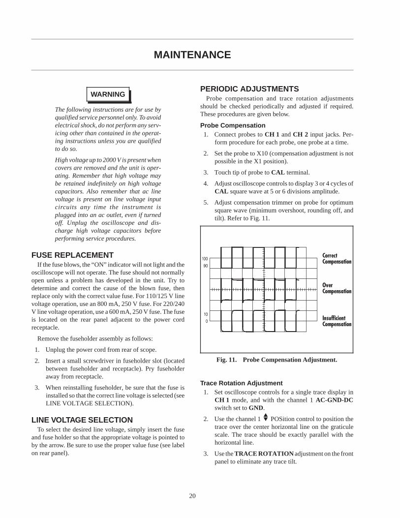
PERIODIC ADJUSTMENTSProbe compensation and trace rotation adjustments
should be checked periodically and adjusted if required.These procedures are given below.
Probe Compensation1. Connect probes toCH 1 andCH 2 input jacks. Per-
form procedure for each probe, one probe at a time.
2. Set the probe to X10 (compensation adjustment is notpossible in the X1 position).
3. Touch tip of probe toCAL terminal.
4. Adjust oscilloscope controls to display 3 or 4 cycles ofCAL square wave at 5 or 6 divisions amplitude.
5. Adjust compensation trimmer on probe for optimumsquare wave (minimum overshoot, rounding off, andtilt). Refer to Fig. 11.
Trace Rotation Adjustment1. Set oscilloscope controls for a single trace display in
CH 1 mode, and with the channel 1AC-GND-DCswitch set toGND.
2. Use the channel 1 POSition control to position thetrace over the center horizontal line on the graticulescale. The trace should be exactly parallel with thehorizontal line.
3. Use theTRACE ROTATION adjustment on the frontpanel to eliminate any trace tilt.
CorrectCompensation
OverCompensation
InsufficientCompensation
Fig. 11. Probe Compensation Adjustment.
20
CALIBRATION CHECKA general check of calibration accuracy may be made by
displaying the output of theCAL terminal on the screen.This terminal provides a square wave of 2 V p-p. This signalshould produce a displayed waveform amplitude of fourdivisions at .5 V/div sensitivity for both channel 1 and 2(with probes set for direct). With probes set for X10, thereshould be four divisions amplitude at 50 mV/div sensitivity.TheVARIABLE controls must be set toCAL during thischeck.
NOTETheCAL signal should be used only as ageneral check of calibration accuracy, notas a signal source for performing recali-bration adjustments; a voltage standardcalibrated at several steps and of 0.3% orbetter accuracy is required for calibrationadjustments.
The CAL signal should not be used as atime base standard.
INSTRUMENT REPAIR SERVICEBecause of the specialized skills and test equipment re-
quired for instrument repair and calibration, many custom-ers prefer to rely uponB+K Precision for this service. Touse this service, even if the oscilloscope is no longer underwarranty, follow the instructions given in the SERVICEINFORMATION portion of this manual. There is a flat ratecharge for instruments out of warranty.
MAINTENANCE
21
APPENDIX
IMPORTANT CONSIDERATIONS FOR RISE TIMEAND FALL TIME MEASUREMENTS
Error in Observed MeasurementThe observed rise time (or fall time) as seen on the CRT
is actually the cascaded rise time of the pulse being meas-ured and the oscilloscope’s own risetime. The two rise timesare combined in square law addition as follows:
Tobserved=
The effect of the oscilloscope’s rise time is almost negli-gible when its rise time is at least 3 times as fast as that ofthe pulse being measured. Thus, slower rise times may bemeasured directly from the CRT. However, for faster risetime pulses, an error is introduced that increases progres-sively as the pulse rise time approaches that of the oscillo-scope. Accurate measurements can still be obtained bycalculation as described below.
Direct MeasurementsThe Models 2125A and 2120B oscilloscopes have a rated
rise time of 12 ns. Thus, pulse rise times of about 36ns orgreater can be measured directly. Most fast rise times aremeasured at the fastest sweep speed and using X10 magni-fication. For the Models 2125A and 2120B, this sweep rateis 10 ns/div. A rise time of less than about four divisions atthis sweep speed should be calculated.
Calculated MeasurementsFor observed rise times of less than 36 ns, the pulse rise
time should be caluclated to eliminate the error introducedby the cascaded oscilloscope rise time. Calculate pulse risetime as follows:
Tpulse=
Limits of MeasurementMeasurements of pulse rise times that are faster than the
scope’s rated rise time are not recommended because a verysmall reading error introduces significant error into thecalculation. This limit is reached when the “observed” risetime is about 1.3 times greater than the scope’s rated risetime, about 16 ns minimum for the Models 2125A and2120B.
Probe ConsiderationsFor fast rise time measurements which approach the limits
of measurement, direct connection via 50Ω coaxial cableand 50 Ω termination is recommended where possible.When a probe is used, its rise time is also cascaded in squarelaw addition. Thus the probe rating should be considerablyfaster than the oscilloscope if it is to be disregarded in themeasurement.
(T ) + (T )pulse2
scope2 (T ) + (T )observed
2scope
2
22

SERVICE INFORMATION
Warranty Service: Please return the product in the original packaging with dated proof of purchase to the address below.Clearly state in writing the performance problem and return any leads, connectors, and accessories that you are using with thedevice.
Non-Warranty Service: Return the product in the original packaging to the address below. Clearly state in writing theperformance problem and return any leads, connectors, and accessories that you are using with the device. Customers not onopen account must include payment in the form of a money order or credit card. For the most current flat-rate repair charges,contact the factory before shipping the product.
Return all merchandise toB+K Precision Corp.with pre-paid shipping. The flat-rate repair charge includes return shippingto locations in North America. For overnight shipments and non-North America shipping fees, contactB+K Precision Corp.
IMPORTANT
Include with the instrument your complete return shipping address, contact name, phone number, and description of problem.
Service DepartmentB+K Precision Corp.1031 Segovia CirclePlacentia, CA 92870
Phone (714) 237-9220Fax (714) 237-9214
E-mail: [email protected]
23

LIMITED WARRANTY
B+K Precision Corp. warrants to the original purchaser that its product, and the component parts thereof, will be free fromdefects in workmanship and materials for a period of three years from the date of purchase (Model 2125A) or two years fromthe date of purchase (Model 2120B).
B+K Precision Corp. will, without charge, repair or replace, at its option, defective product or component parts upondelivery to an authorizedB+K Precision service contractor or the factory service department, accompanied by proof of thepurchase date in the form of a sales receipt.
To obtain warranty coverage in the U.S.A., this product must be registered by completing and mailing the enclosed warrantyregistration card toB+K Precision, 1031 Segovia Circle, Placentia, CA 92870 within fifteen (15) days from the date ofpurchase.
Exclusions: This warranty does not apply in the event of misuse or abuse of the product or as a result of unauthorizedalterations or repairs. It is void if the serial number is altered, defaced or removed.
B+K Precision Corp. shall not be liable for any consequential damages, including without limitation damages resultingfrom loss of use. Some states do not allow limitation of incidental or consequential damages, so the above limitation orexclusion may not apply to you.
This warranty gives you specific rights and you may also have other rights which vary from state to state.
24

INFORMATION
One of the best tutorials on oscilloscopes in the industry. Valuable to those with little knowledgeof oscilloscopes as well as the experienced technician or engineer who wishes
to refresh their memory or explore new uses for oscilloscopes.
Download your FREE copyfrom our Web site
www.bkprecision.com

© 2000 B+K Precision Corp.
481-312-9-001 Printed in Taiwan
+ ®
1031 Segovia Circle, Placentia, CA 92870