instrucciones de instalaciÓn y uso installation ... · instrucciones de instalaciÓn y uso...
TRANSCRIPT

INSTRUCCIONES DE INSTALACIÓN Y USO
INSTALLATION INSTRUCTIONS AND USER GUIDE
MATTIRA CALDERAS ELÉCTRICAS MODULANTES DIGITALES
DIGITAL MODULATING ELECTRIC BOILERS
PARA CALEFACCIÓN / FOR CENTRAL HEATING
MAS18
MAS15
Por favor, lea estas instrucciones atentamente antes de instalar o utilizar el aparato por primera vez. Estas instrucciones deben ser seguidas para una
instalación segura de la caldera. Cualquier problema, fallo o daño ocasionado por la no observancia de estas instrucciones no será cubierto por la garantía del
fabricante. Este manual debe ser guardado con el aparato por el usuario para futuras consultas.
Please read these instructions before installing or using this appliance for the first time. These instructions must be followed for the safe installation of the boiler. Any
problem, fault or damage caused by the non-observance of these instructions will not be covered under the manufacturer’s warranty. This manual should be retained with
the appliance by the user for future reference.

2
INDICE
1 IMPORTANTE 3
2 SEGURIDAD 3
3 INTRODUCCIÓN 3
3.1 DISEÑO Y FUNCIONAMIENTO 3
3.2 PRINCIPALES COMPONENTES 3
3.3 SITUACIÓN DE COMPONENTES 4
3.4 DISPOSITIVOS DE SEGURIDAD 4
4 INSTALACIÓN 4
4.1 REQUISITIOS GENERALES 5
4.2 DESEMBALAJE Y CONTENIDO 5
4.3 EMPLAZAMIENTO 5
4.4 DIMENSIONES Y CONEXIONES 5
4.5 DISTANCIAS MÍNIMAS 5
4.6 SOPORTE DE MONTAJE 6
4.7 CONEXIONES HIDRÁULICAS 6
4.8 CONDUCCIÓN VÁLVULA DE SEGURIDAD 7
4.9 BOMBA DE CIRCULACIÓN 7
4.10 CONEXIÓN ELÉCTRICA 7
4.11 CONEXIÓN DE UN TERMOSTATO DE
AMBIENTE 9
4.12 CONEXIÓN DE UNA SONDA DE
TEMPERATURA EXTERIOR 9
5 PUESTA EN MARCHA 9
5.1 PARÁMETROS DE INSTALACIÓN 9
5.2 LIMITACIÓN DE LA POTENCIA MÁXIMA 10
5.3 ENJUAGE CIRCUITO DE CALEFACCIÓN 11
5.4 CALEFACCIÓN, LLENADO INICIAL 12
5.5 COMPROBACIÓN DE LA BOMBA 12
5.6 VISUALIZACIÓN DE OTROS DATOS 12
6 INSTRUCCIONES DE USO DE LA CALDERA
6.1 ENCENDIDO INICIAL 13
6.2 DESCRIPCIÓN DEL CUADRO DE MANDOS 13
6.3 CALEFACCIÓN 14
6.4 MODO ANTI-HIELO 14
6.5 PARÁMETROS DE USUARIO 15
6.6 MODULACIÓN EN CALEFACCIÓN 15
6.7 REGULACIÓN DE LA CALEFACCIÓN EN
FUNCIÓN DE LA TEMPERATURA EXTERIOR 15
6.8 BLOQUEO DEL CUADRO DE MANDOS 16
6.9 FUNCIÓN ANTI BLOQUEO DE LA BOMBA 16
7 PROBLEMAS Y SOLUCIONES 17
7.1 POSIBLES FALLOS Y SOLUCIONES 17
7.2 SOBRECALENTAMIENTO Y REARME 18
7.3 DETECTOR DE CAUDAL, ERROR E3 18
7.4 COMPROBACIÓN DE LA POTENCIA
ENCALEFACCIÓN 18
8 LISTA DE PRINCIPALES RECAMBIOS 19
9 MANTENIMIENTO 19
10 INFORMACION MEDIO AMBIENTAL 19
11DATOS TÉCNICOS 20
12 ESQUEMAS ELÉCTRICOS 21
DECLARACIÓN DE CONFORMIDAD CE 22

3
1 IMPORTANTE
Las siguientes instrucciones de instalación guiarán a la
persona competente durante todo el proceso de
instalación.
La garantía de la caldera no cubrirá cualquier daño causado
por la no observancia de alguna de estas instrucciones.
Este manual debe ser conservado y dado a cualquier nuevo
usuario.
Los símbolos usados en el texto se explican a continuación:
ADVERTENCIA Esta indicación muestra la
posibilidad de causar la muerte
por electrocución.
ADVERTENCIA Esta indicación muestra la
posibilidad de causar la
muerte o graves lesiones.
PRECAUCIÓN Esta indicación muestra la
posibilidad de causar solo
lesiones o daños a las cosas.
Símbolo para información útil.
2 SEGURIDAD
o Este aparato no está destinado a ser usado por
personas (incluidos niños) cuyas capacidades físicas,
sensoriales o mentales estén reducidas o carezcan de
conocimiento del uso del aparato, salvo si son
supervisados o instruidos por una persona
responsable de su seguridad.
o Compruebe que el voltaje de la placa de
características de la caldera coincide con el voltaje de
la red donde se va a conectar.
o El uso de estas calderas está prohibido en presencia de
gases, explosivos u objetos inflamables.
o Las salidas y entradas de aire de la caldera aseguran el
correcto funcionamiento y protegen de
sobrecalentamientos, no se deben tapar nunca.
o Esta caldera debe ser desconectada de la red eléctrica
antes de efectuar cualquier reparación en su interior.
o La caldera debe ser instalada de tal forma que los
interruptores u otros controles no puedan ser
tocados por alguien que esté usando el baño o la
ducha.
o La instalación debe ser efectuada de acuerdo con la
legislación eléctrica vigente.
o Este aparato está destinado a ser permanentemente
conectado a una instalación fija. El circuito de
alimentación de la caldera debe incorporar un
interruptor de corte omnipolar con una separación de
contactos de al menos 3 mm.
o El circuito de alimentación de la caldera debe
incorporar un interruptor diferencial.
o Esta caldera debe ser conectada a tierra.
o Todos los modelos incorporan distintos dispositivos
de seguridad. En caso de actuación de uno o varios de
ellos acuda a la sección 7 PROBLEMAS Y
SOLUCIONES.
o La presencia en el aire de humo, polvo y polución
puede, con el tiempo, manchar las paredes y zonas
próximas al aparato.
o Se prohíbe cualquier uso impropio.
o No instalar la caldera en habitaciones en las que pueda
helar.
3 INTRODUCCIÓN
3.1 DISEÑO Y FUNCIONAMIENTO
Las calderas Gabarrón MATTIRA MAS18 y MAS15 son
equipos eléctricos que proporcionan calefacción
centralizada por agua a través de un sistema estándar de
radiadores (o un sistema de suelo radiante con un kit
especial).
Las potencias van de los 2 a los 18kW. La potencia máxima
puede ser ajustada a las necesidades caloríficas del sistema
o a la limitación del suministro eléctrico. Pueden funcionar
en trifásico 3x400V+N o en monofásico 230V~ (la
configuración estándar admite hasta un máximo de 12kW
en monofásico).
Las calderas están diseñadas para ser instaladas en interior
en una pared adecuada considerando el peso total del
aparato.
Un cuadro de mandos digital proporciona al usuario control
sobre la temperatura de calefacción. La característica de
calefacción modulante ajusta la potencia a la demanda para
asegurar un funcionamiento económico. Un termostato de
ambiente externo deberá ser instalado. Todos los
componentes para un sistema de calefacción central están
integrados.
3.2 PRINCIPALES COMPONENTES
• Calderín de acero aislado con resistencias de acero
inoxidable INCOLOY800.
• Tarjetas electrónicas incorporadas que controlan la
temperatura, el funcionamiento modulante, la bomba,
antibloqueo de bomba y protección anti-hielo. Auto
diagnóstico e información de fallos.
• Sistema cerrado de calefacción con bomba de
circulación, vaso de expansión, purgador automático,
válvula de seguridad de 3bar, reloj indicador de
presión, detector de caudal y termostato de seguridad.
• Silenciosos controladores de potencia TRIAC.
• Cuadro de mandos digital.
i
4
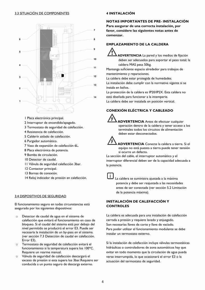
3.3 SITUACIÓN DE COMPONENTES
1 Placa electrónica principal.
2 Interruptor de encendido/apagado.
3 Termostato de seguridad de calefacción.
4 Resistencia de calefacción.
5 Calderín aislado de calefacción.
6 Purgador automático.
7 Vaso de expansión de calefacción 6L.
8 Placa electrónica de potencia.
9 Bomba de circulación.
10 Detector de caudal.
11 Válvula de seguridad calefacción 3bar.
12 Contactor principal.
13 Bornas de conexión.
14 Reloj indicador de presión en calefacción.
3.4 DISPOSITIVOS DE SEGURIDAD
El funcionamiento seguro en todas circunstancias está
asegurado por los siguientes dispositivos:
o Detector de caudal de agua en el sistema de
calefacción que evitará el funcionamiento en caso de
bloqueo. Si el caudal del sistema está por debajo del
nivel permitido se producirá el error E3. Puede ser
necesaria la instalación de un by-pass en el sistema.
(ver sección 7.3 Detección de caudal en calefacción.
Error E3).
o Termostato de seguridad de calefacción evitará el
funcionamiento si la temperatura supera los 100ºC.
Requiere un rearme manual.
o Válvula de seguridad de calefacción descargará el
exceso de presión si esta supera los 3bar.Requiere ser
conducida a un punto seguro de descarga externo.
4 INSTALACIÓN
NOTAS IMPORTANTES DE PRE- INSTALACIÓN
Para asegurar de una correcta instalación, por
favor, considere las siguientes notas antes de
comenzar.
EMPLAZAMIENTO DE LA CALDERA
ADVERTENCIA La pared y los medios de fijación
deben ser adecuados para soportar el peso total; la
caldera MAS pesa 50kg.
Mantenga suficiente espacio alrededor para trabajos de
mantenimiento y reparaciones.
La caldera debe estar protegida de humedades.
La instalación debe cumplir con la normativa vigente si se
instala en baños.
La protección de la caldera es IP20/IP2X. Esta caldera no
está diseñada para funcionar a la intemperie.
La caldera debe ser instalada en posición vertical.
CONEXIÓN ELÉCTRICA Y CABLEADO
ADVERTENCIA Antes de efectuar cualquier
operación dentro de la caldera y tener acceso a los
terminales todos los circuitos de alimentación
deben estar desconectados.
ADVERTENCIA Conecte la caldera a tierra. Si el
equipo no está puesto a tierra puede tener tensión
si ocurre un defecto.
La sección del cable, el interruptor automático y el
interruptor diferencial deben ser de la capacidad adecuada a
la potencia.
La caldera se suministra ajustada a la máxima
potencia y debe ser reajustada a las necesidades
antes de ser conectada (ver sección 5.2 Limitación
de la potencia máxima).
INSTALACIÓN DE CALEFACCIÓN Y
CONTROLES
La caldera es adecuada para una instalación de calefacción
cerrada a presión y requiere lavado y enjuagado.
Son necesarias llaves de corte y llave de vaciado.
Para poder utilizar el funcionamiento modulante se debe
instalar un termostato externo.
Si la instalación de calefacción incluye válvulas termostáticas
hidráulicas o controladores de zona automáticos hay que
evitar en todo momento que la circulación de agua pueda
verse interrumpida, lo que ocasionará el error E3 o la
actuación del termostato de seguridad.
i

5
A ida calefacción3/4"
B retorno calefacción 3/4"
C desagüe válvula seguridad
D acometida eléctrica
4.1 REQUISITOS GENERALES
La instalación debe ser efectuada por una persona
competente de acuerdo con la legislación vigente.
La instalación también debe respetar toda la normativa
vigente, así como los reglamentos pertinentes
4.2 DESEMBALAJE Y CONTENIDO
-Soporte a la pared
con plantilla.
- Caldera.
- Documentación.
- Bolsa con puentes.
Lleve el embalaje de cartón un punto limpio o a un centro
de reciclado. Observe la normativa vigente.
4.3 EMPLAZAMIENTO
ADVERTENCIA INSTALAR EN POSICIÓN
VERTICAL EN UNA PARED CAPAZ DE
SOPORTAR TODO EL PESO DE LA CALDERA
50kg.
El lugar de emplazamiento debe estar limpio y seco y sin
presencia de gases, explosivos u objetos inflamables.
El equipo no es adecuado para su instalación en exteriores
y debe ser protegido de la humedad y de heladas.
La caldera debe ser instalada de tal forma que los
interruptores u otros controles no puedan ser tocados por
alguien que esté usando el baño o la ducha. No debe existir
posibilidad de que el agua gotee o salpique a la caldera.
Existe normativa específica para la instalación en baños o en
zonas de duchas.
Cuando sea posible la caldera debe instalarse lo más cerca
posible de los puntos de suministro de agua caliente.
Los cables de alimentación deben ser conducidos de
manera conveniente y se debe instalar un interruptor
general y un interruptor diferencial.
4.4 DIMENSIONES Y CONEXIONES
4.5 DISTANCIAS MÍNIMAS
A: 50 mm B: 10 mm C: 200 mm
Deben respetarse las distancias mínimas entre las diversas
partes de la caldera y las superficies circundantes del
alojamiento. Una distancia mínima de 200 mm debe
respetarse por debajo de la caldera para poder reemplazar
la resistencia si fuera necesario. Una distancia mínima de
500 mm debe respetarse enfrente de la caldera para
permitir labores de mantenimiento.
Proporcione suficiente espacio para realizar todas las
conexiones hidráulicas incluyendo las conducciones de las
válvulas de seguridad a un punto seguro de descarga.

6
4.6 SOPORTE DE MONTAJE
Marque en la pared los puntos de sujeción usando el soporte de montaje como plantilla según el esquema.
Sujete el soporte de forma segura en la pared antes de elevar la caldera a su posición. Taladre los agujeros y fije el soporte
comprobando el nivel y utilizando tornillos de alta resistencia con tacos apropiados con un diámetro mínimo de 10mm.
Solicite siempre asistencia si lo necesita. Use guantes adecuados resistentes a los cortes cuando maneje la caldera y el
soporte.
Asegúrese de emplear técnicas de elevación seguras. No eleve la caldera sujetando las tuberías o componentes.
Asegúrese de que las sujeciones a la pared soportarán la carga. Compruebe la calidad de la pared.
4.7 CONEXIONES HIDRÁULICAS
PRECAUCIÓN Las conexiones hidráulicas deben realizarse respetando la ida y retorno marcados.
PRECAUCIÓN Cuando apriete o afloje las conexiones roscadas, utilice siempre herramientas adecuadas como llaves
abiertas. No utilice tenazas, mordazas o extensiones que pueden causar daños o fugas de agua.
Instale purgadores en los radiadores en los puntos altos de la instalación.
Calefacción Ida y Retorno
Estas conexiones son de ¾“ para la conexión de tubería de 22 mm. En este punto deben instalarse llaves de corte que
permitan aislar la caldera sin tener que vaciar toda la instalación. Las válvulas deben tener el calibre adecuado para no
obstruir la circulación del agua.
No es recomendable utilizar instalaciones mono tubo, sólo se deberían utilizar instalaciones de dos tubos.
Punto de vaciado
Un punto de vaciado debe ser instalado en la parte más baja de la instalación. No es aceptable el vaciado de la caldera a
través de la válvula de seguridad porque las impurezas y depósitos podrían afectar al funcionamiento correcto de la válvula.
By-pass en la instalación de calefacción
El detector de caudal en calefacción requiere un caudal mínimo de 7L por minuto para un funcionamiento correcto.
Las instalaciones con válvulas termostáticas necesitarán un by-pass para garantizar el caudal suficiente, aunque todas las
válvulas termostáticas estén cerradas (ver sección 7.3 Detección de caudal en calefacción. Error E3).
i

7
Vaso de expansión
Un vaso de expansión integrado de 6L proporciona la expansión necesaria a la instalación en condiciones normales de
funcionamiento, sin embargo, una instalación con mayores volúmenes de agua puede necesitar una capacidad de expansión
extra.
4.8 CONDUCCIÓN VÁLVULA DE SEGURIDAD
La válvula de seguridad de 3bar de calefacción puede descargar agua hirviendo y debe ser conducida a un punto seguro pero
visible, como por ejemplo un sumidero, donde cualquier descarga no cause daños o lesiones.
PRECAUCIÓN: La conducción de la válvula de seguridad debe realizarse por una persona competente.
El material de la tubería de descarga debe ser capaz de conducir agua / vapor a 100ºC.
Todas las instalaciones deben se efectuadas de acuerdo a la normativa local en vigor en ese momento. El no cumplimiento de
esta normativa anula la garantía del fabricante.
4.9 BOMBA DE CIRCULACIÓN
La caldera equipa una bomba de circulación de alta eficiencia, con una altura manométrica máxima de 6.2 m y un caudal
máximo de 3.3 m³/h.
El botón de mando incorporado, permite seleccionar el modo de funcionamiento de la bomba. Es posible seleccionar
velocidades constantes de funcionamiento I, II y III.
Un indicador LED informa del estado de funcionamiento de la bomba:
- Color verde: Funcionamiento correcto.
- Parpadeo verde/rojo: Baja tensión U<180V; sobretensión U>253V; sobretemperatura del módulo.
- Parpadeo rojo: Bomba bloqueada.
4.10 CONEXIÓN ELÉCTRICA
Conexión al suministro eléctrico
Las calderas MAS15 y MAS18 deben ser instaladas en redes de suministro que tengan una impedancia de no más de 0.25 +
j0.25Ω.
Las calderas MAS15 y MAS18 cumplen con los requisitos técnicos de la EN 61000-3-3.
Las calderas MAS15 y MAS18 deben ser instaladas en redes de suministro con una capacidad de servicio ≥100 A por fase.
Complete todo el trabajo de fontanería antes de conectar la caldera a la red eléctrcia.
Cualquier reinstalación debe ser efectuada por electricistas cualificados.
Compruebe que el voltaje de la placa de características de la caldera coincide con el voltaje de la red donde se va a conectar.
ADVERTENCIAEL CABLE DE ALIMENTACIÓN DEBE SER DEL TAMAÑO ADECUADO A LA POTENCIA
REQUERIDA. DEBE ESTAR CABLEADO A TRAVÉS DE UN INTERRUPTOR DE CORTE GENERAL CON UN DISTANCIA
ENTRE CONTACTOS MÍNIMA DE 3mm EN TODOS LOS POLOS Y PROTEGIDO POR UN INTERRUPTOR
DIFERENCIAL ADECUADO. Instale las protecciones eléctricas indicadas en la normativa vigente. En caso de que no se
cumpla esta normativa el fabricante no será responsable de lesiones a las personas o daños materiales que pudieran ocurrir.
ADVERTENCIAES ESENCIAL QUE LA CALDERA ESTÉ CONECTADA A TIERRA y el cableado comprobado de
acuerdo a la normativa vigente.

8
Secciones de cables de alimentación
La siguiente tabla muestra las secciones mínimas recomendadas para una caldera en conexión trifásica 3x400V+N~.
La siguiente tabla muestra las secciones mínimas recomendadas para una caldera en conexión monofásica 230V~.
*La configuración estándar sólo admite conexión MONOFÁSICA 230V~ hasta un máximo de 12kW de potencia.
Conexión a la caldera
ADVERTENCIA: El contacto con partes activas puede causar serios daños personales.
Antes de realizar la conexión desconecte el suministro eléctrico. Asegúrese de que el suministro eléctrico no puede ser
restablecido de nuevo. Las conexiones principales permanecen activas incluso cuando el interruptor encendido/apagado este
apagado.
La caldera se suminstra preparada para funcionar en trifásico 3x400V. Para funcionamiento en monofásico 230V se deben
utilizar dos conexiones puente en la borna de conexiones como se muestra a continuación.
Las bornas de conexión se encuentran después de retirar el panel frontal de la caldera. Los cables de alimentación deben ser
conducidos de forma segura a este punto a través de la protección pasamuros de la parte posterior de la caldera.
PRECAUCIÓN: Una conexión incorrecta en las bornas de conexión puede destruir la electrónica.
Asegúrese de que los cables están apretados de manera segura a las bornas de conexión. i
Potencia de la caldera 4kW 5kW 6kW 7kW 8kW 9kW 10kW 11kW 12kW 13kW 15kW 18kW
Corriente maxima
modulando 13.0A 13.0A 13.0A 13.0A 13.0A 13.0A 21.7A 21.7A 21.7A 21.7 21.7A 26.0A
Calibre de los interruptores 16A 16A 16A 16A 16A 16A 25A 25A 25A 25A 25A 32A
Mínima sección de cables 4mm 4mm 4mm 4mm 4mm 4mm 6mm 6mm 6mm 6mm 6mm 10mm
Potencia de la caldera 4kW 5kW 6kW 7kW 8kW 9kW 10kW 11kW 12kW 13kW 15kW 18kW
Corriente máxima 17.4A 21.7A 26.1A 30.4A 34.8A 39.1A 43.5A 47.8A 52.2A 56.5A* 65.2A* 78.3A*
Calibre de los interruptores 20A 25A 32A 32A 40A 50A 50A 50A 63A 63A* 80A* 80A*
Mínima sección de cables 4mm 6mm 10mm 10mm 10mm 16mm 16mm 16mm 16mm 25mm 25mm 35mm

9
Cableado de controles externos
Se recomienda que la caldera sea comandada por un control externo como un termostato de ambiente o un crono
termostato programador como el Gabarrón modelo CTP-10.
PRECAUCIÓN: La conexión de este control debe ser LIBRE de VOLTAJE y conectada a los terminales indicados
‘TA’ en la placa electrónica princial. El puente instalado en fabrica entre estos terminales debe ser retirado.
La modulación automática de la potencia de la caldera se activa con la actuación inicial de este control externo.
4.11 CONEXIÓN DE TERMOSTATO DE AMBIENTE
Un termostato de ambiente con contactos libres de tensión puede ser conectado para regular la instalación de
calefacción. Si queremos aprovechar el funcionamiento modulante de la caldera el uso de un termostato de ambiente es
obligatorio.
Conecte el termostato de ambiente a los bornes marcados con TA en la placa principal. Ver “12 ESQUEMAS ELÉCTRICOS”.
4.12 CONEXIÓN DE UNA SONDA DE TEMPERATURA EXTERIOR
Una sonda de temperatura en el exterior de la vivienda puede ser conectada a la caldera para poder activar el modo
regulación de la calefacción en función de la temperatura exterior.
Conecte una termistancia NTC de 10kΩ a 25ºC en los bornes marcados con T.EXT en la placa principal. . Ver “12
ESQUEMAS ELÉCTRICOS”.
5 PUESTA EN MARCHA
5.1 PARÁMETROS DE INSTALACIÓN
El instalador debe configurar una serie de parámetros para ajustar las distintas funciones de la caldera a las necesidades de la
instalación.
Para acceder al menú de parámetros de instalación, estando la caldera en OFF, pulsar la tecla y la tecla
simultáneamente durante 5”.
Para avanzar o retroceder por el menú utilizaremos las teclas y respectivamente.
Para modificar un parámetro pulsaremos la tecla y veremos el valor actual que podrá ser modificado con las teclas
y . Pulsar de nuevo la tecla .
Una vez ajustados los distintos parámetros es necesario validarlos pulsando la tecla durante 3”. Si no existe actividad,
transcurridos 30” desde el acceso, el menú de parámetros de instalación será cerrado sin validar ningún cambio.

10
Tipo de caldera. Para las calderas MAS18 y MAS15 el valor de este parámetro es 0.
Modelo. 18 corresponde al modelo MAS18, 15 corresponde al modelo MAS15.
Limitación de la potencia máxima.
El modelo MAS18 puede ser limitado a 18 - 15 -12 - 9 - 6 - 3 kW.
El modelo MAS15 puede ser limitado a 15 - 13 -12 - 11 - 10 - 9 - 8 - 7 - 6 - 5 - 4 - 3 - 2 kW.
Suelo radiante. Si la caldera está preparada para una instalación de suelo radiante (es necesario equipar
limitador especial) el valor de este parámetro será 1, en caso contrario será 0.
Sonda exterior. Una sonda (no suministrada) de temperatura en el exterior de la vivienda puede ser
instalada. En este caso el valor de este parámetro será 1.
Diferencial calefacción. El diferencial de calefacción puede ser ajustado desde 2ºC a 10ºC. El valor por
defecto es 2ºC.
Modulación. Valores posibles: 1 (modulación activada) 0 (modulación desactivada).
Unidades. Es posible cambiar las unidades de grados Celsius a Fahrenheit. Por defecto ºC.
Calefacción AUTO. Si una sonda de temperatura en el exterior de la vivienda se encuentra instalada, es
posible activar la calefacción automática. Valores posibles: 1 (activada) 0 (desactivada).
TIMAX. Temperatura máxima de impulsión del agua en calefacción AUTO.
TIMIN. Temperatura mínima de impulsión del agua en calefacción AUTO.
TEMAX. Temperatura exterior a partir de la cual el agua en calefacción será impulsada a TIMIN.
TEMIN. Temperatura exterior por debajo de la cual el agua en calefacción será impulsada a TIMAX.
5.2 LIMITACIÓN DE LA POTENCIA MÁXIMA
La caldera se suministra para un funcionamiento a máxima potencia de 15 ó 18kW según modelos. La potencia puede ser
limitada para ajustarse a las necesidades térmicas de la instalación. El ajuste se realiza mediante el parámetro P03. Ver arriba
“5.1 PARÁMETROS DE INSTALACIÓN”.
ADVERTENCIA: AJUSTAR SIEMPRE LA POTENCIA MÁXIMA DE LA CALDERA TENIENDO EN CUENTA LA
CAPACIDAD DE LA INSTALACIÓN ELÉCTRICA ANTES DE CONECTAR LA CALDERA.
La caldera nunca excederá este valor máximo de potencia, pero sí que modulará en calefacción, adaptando la demanda y
asegurando un funcionamiento económico.
La correcta configuración de la potencia seleccionada debe ser comprobada en el display de la caldera siguiendo el
procedimiento descrito en la sección “7.4 COMPROBACIÓN DE LA POTENCIA EN CALEFACCIÓN”.

11
PRECAUCIÓN: Es esencial comprobar la potencia con una pinza amperimétrica.
LIMITACIÓN DE POTENCIA EN MODELO MAS18
CONEXIÓN TRIFÁSICA 3x400V~+N CONEXIÓN 230V~
LIMITACIÓN DE POTENCIA EN MODELO MAS15
CONEXIÓN TRIFÁSICA 3x400V~+N CONEXIÓN 230V~
*La configuración estándar sólo admite conexión MONOFÁSICA 230V~ hasta un máximo de 12kW de potencia.
5.3 ENJUAGUE CIRCUITO DE CALEFACCIÓN
PRECAUCIÓN: Enjuague totalmente la instalación de calefacción antes de la instalación.
La instalación de calefacción debe ser enjuagada, lo cual eliminará contaminantes y partículas que pueden afectar al
funcionamiento y vida útil de la caldera. Cualquier limpiador o aditivo que se utilice debe cumplir con la normativa vigente y
las instrucciones del fabricante han de ser seguidas.
NOTA: ES IMPORTANTE NO EMPLEAR LA VÁLVULA DE SEGURIDAD DE LA CALDERA PARA VACIAR O ENJUAGAR
LA INSTALACIÓN PORQUE LAS IMPUREZAS Y PARTICULAS ATRAPADAS PODRÍAN AFECTAR AL
FUNCIONAMIENTO CORRECTO DE LA VÁLVULA.
Utilizar el punto de vaciado de la instalación.
Potencia
máxima
limitada a:
INTENSIDAD
MÁXIMA
L1
INTENSIDAD
MÁXIMA
L2
INTENSIDAD
MÁXIMA
L3
18kW 26.0A 26.0A 26.0A
15kW 26.0A 26.0A 13.0A
12kW 26.0A 13.0A 13.0A
9kW 13.0A 13.0A 13.0A
6kW 13.0A 13.0A -
3kW 13.0A - -
Potencia
máxima
limitada a:
INTENSIDAD
MÁXIMA
18kW* 78.3A*
15kW* 65.2A*
12kW 52.2A
9kW 39.1A
6kW 26.1A
3kW 13.0A
Potencia
máxima
limitada a:
INTENSIDAD
MÁXIMA
L1
INTENSIDAD
MÁXIMA
L2
INTENSIDAD
MÁXIMA
L3
15kW 21.7A 21.7A 21.7A
13kW 21.7A 21.7A 13.0A
12kW 8.7A 21.7A 21.7A
11kW 21.7A 13.0A 13.0A
10kW 13.0A 8.7A 21.7A
9kW 13.0A 13.0A 13.0A
8kW 13.0A 8.7A 13.0A
7kW 8.7A 13.0A 8.7A
6kW 8.7A 8.7A 8.7A
5kW 8.7A 13.0A -
4kW - 8.7A 8.7A
3kW 13.0A - -
2kW - - 8.7A
Potencia
máxima
limitada a:
INTENSIDAD
MÁXIMA
15kW* 65.2A*
13kW* 56.5A*
12kW 52.2A
11kW 47.8A
10kW 43.5A
9kW 39.1A
8kW 34.8A
7kW 30.4A
6kW 26.1A
5kW 21.7A
4kW 17.4A
3kW 13.0A
2kW 8.7A

12
5.4 CALEFACCIÓN, LLENADO INICIAL
Asegúrese de que las llaves de corte estén abiertas. Localice el purgador automático en la parte superior de la caldera y afloje
el pequeño tapón. Cierre los purgadores manuales de la instalación.
Tenga cuidado de no salpicar ninguno de los componentes eléctricos.
Llene lentamente hasta que la aguja del reloj marque una presión de entre 1 y 1.5bar.
Proceda a purgar manualmente todos los radiadores hasta que todo el aire sea eliminado de la instalación. Será necesario
reajustar el valor de presión durante esta operación, rellenando la instalación hasta que la aguja del reloj marque una presión
de entre 1 y 1.5bar.
5.5 COMPROBACIÓN DE LA BOMBA
En algunas ocasiones, como por ejemplo ante un error E3, es necesario comprobar que la bomba está convenientemente
purgada y que gira libremente.
Para purgar la bomba, encienda la caldera y, mediante el selector de la bomba, alterne la posición III con la posición Min cada
quince segundos. Realice esta operación durante 5 minutos.
Si el exceso de aire permanece en la instalación o no existe caudal suficiente la caldera mostrará fallo en el display con el
código E3.
Un indicador LED informa del estado de funcionamiento de la bomba:
- Color verde: Funcionamiento correcto.
- Parpadeo verde/rojo: Baja tensión U<180V; Sobretensión U>253V; Sobretemperatura del módulo.
- Parpadeo rojo: Bomba bloqueada.
5.6 VISUALIZACIÓN DE OTROS DATOS
Manteniendo pulsada la tecla durante unos segundos y mediante las teclas y se visualizan otros datos de la
instalación.
Temperatura en el sensor de retorno de calefacción.
Potencia máxima limitada.
Potencia actual modulando.
Temperatura en el sensor del exterior de la vivienda (si instalado y P05 activado).

13
6 INSTRUCCIONES DE USO DE LA CALDERA
6.1 ENCENDIDO INICIAL
PRECAUCIÓN:LA POTENCIA MÁXIMA LIMITADA DEBE SER AJUSTADA ANTES DEL ENCENDIDO INICIAL.
LA CALDERA NUNCA DEBE SER ENCENDIDA CON LA INSTALACIÓN DE CALEFACCIÓN O EL
DEPÓSITO DE ACS VACÍOS. PUEDEN OCURRIR DAÑOS.
Cuando la caldera se conecta por primera vez se completará un
auto diagnóstico general y si se detecta un fallo será indicado en el display
con un código.
Encienda la caldera mediante el interruptor de encendido/apagado
situado en la parte posterior.
6.2 DESCRIPCIÓN DEL CUADRO DE MANDOS
Pulse la tecla para encender la caldera. Esta misma tecla apaga la caldera al pulsar de nuevo.
Si la función de calefacción no está encendida el display correspondiente sólo mostrará un punto rojo.
6.3 CALEFACCIÓN
Primero asegúrese de que los controles externos como termostatos de ambiente se encuentran demandando calor.
Encienda la función calefacción pulsando la tecla . Pulsándola de nuevo apagará la
función calefacción y el display mostrará otra vez sólo un punto rojo.
Cuando la función calefacción esté encendida el display mostrará la temperatura del
agua de calefacción.
i
Aumentar
temperatura
del agua de
calefacción
Temperatura de
calefacción y
otros mensajes Tecla encendido/apagado
bloqueo/desbloqueo de
teclado
Block / Unblock
Tecla encendido/apagado
calefacción
Indicador de
funcionamiento
resistencias
calefacción
Disminuir
temperatura
del agua de
calefacción

14
El ajuste de la temperatura de la calefacción puede ser modificado pulsando la tecla o la tecla y usando estas
mismas teclas variando el valor que aparece en el display. El nuevo ajuste será almacenado automáticamente al cabo de unos
segundos o instantáneamente si pulsamos la tecla .
La temperatura del agua de calefacción puede ser modificada entre 8ºC y 85°C.
El símbolo H aparece detrás del valor 85 o antes del valor 8.Si seleccionamos esté valor la calefacción funcionara en modo
anti-hielo.
Si el ajuste es mayor que la temperatura del agua de calefacción y el control externo
demanda calor y, además, el ACS no está conectado, las resistencias de calefacción se
encenderán y un pequeño punto rojo se encenderá en el display.
6.4 MODO ANTI-HIELO
Es posible seleccionar un funcionamiento anti-hielo para proteger la instalación y la caldera de heladas en períodos de
inactividad. Se debe mantener conectada la caldera.
Intentando seleccionar un valor inferior a 8ºC o superior a 85ºC aparecerá el símbolo H en el display. Seleccionando este
valor la calefacción sólo funcionará en modo anti-hielo. Si la temperatura del agua de calefacción cae por debajo de los 7ºC la
calefacción se activará automáticamente.
6.5 PARÁMETROS DE USUARIO.
Es posible modificar una serie de parámetros para ajustar algunas funciones de la caldera a las necesidades de cada usuario.
Para acceder al menú de parámetros de usuario, estando la caldera en OFF, pulsar la tecla y la tecla
simultáneamente durante unos segundos.
Para avanzar o retroceder por el menú utilizaremos las teclas y respectivamente.
Para modificar un parámetro pulsaremos la tecla y veremos el valor actual que podrá ser modificado con las teclas
y . Pulsar de nuevo la tecla para validar.
Modulación. Valores posibles: 1 (modulación activada) 0 (modulación desactivada).
Unidades. Es posible cambiar las unidades de grados Celsius a Fahrenheit. Por defecto ºC.
Calefacción AUTO. Si una sonda de temperatura en el exterior de la vivienda se encuentra instalada, es
posible activar la calefacción automática. Valores posibles: 1 (activada) 0 (desactivada). Si el parámetro P05 no
se encuentra activado no se mostrarán ni este parámetro ni los siguientes.
TIMAX. Temperatura máxima de impulsión del agua en calefacción AUTO. Si el parámetro P05 no se
encuentra activado este parámetro no se mostrará.
TIMIN. Temperatura mínima de impulsión del agua en calefacción AUTO. Si el parámetro P05 no se
encuentra activado este parámetro no se mostrará.
TEMAX. Temperatura exterior a partir de la cual el agua en calefacción será impulsada a TIMIN. Si el
parámetro P05 no se encuentra activado este parámetro no se mostrará.
TEMIN. Temperatura exterior por debajo de la cual el agua en calefacción será impulsada a TIMAX. Si el
parámetro P05 no se encuentra activado este parámetro no se mostrará.

15
6.6 MODULACIÓN EN CALEFACCIÓN
La gestión electrónica de la caldera modulará automáticamente la potencia de la calefacción para adecuarla a la demanda y
ahorrar energía.
Esta función trabaja con la caldera “aprendiendo” y anticipando el tiempo necesario para alcanzar el nivel de temperatura del
control externo. La potencia se ajusta automáticamente en días menos fríos o cuando hay presente otra fuente de calor
Para activar esta función hay que retirar el puente entre los terminales TA de la placa electrónica principal y conectar en su
lugar un termostato de ambiente externo libre de voltaje.
Esta función puede desactivarse con el parámetro P08. Ver “6.5 PARÁMETROS DE USUARIO”.
6.7 REGULACIÓNDE LA CALEFACCIÓN EN FUNCIÓN DE LA TEMPERATURA EXTERIOR.
Es posible regular la temperatura a la que la caldera impulsa el agua del circuito de calefacción en función de la temperatura
existente en el exterior de la vivienda. Este método de regulación proporciona el máximo confort al anticiparse a las
variaciones de las necesidades térmicas de la vivienda. El termostato de ambiente sigue regulando la temperatura del interior
de la vivienda.
Para poder activar este modo de funcionamiento de la calefacción, será necesario que el instalador conecte una sonda de
temperatura exterior (no suministrada) y activar los parámetros P05 y P11.
Existen cuatro parámetros que definen esta función.
TIMAX Temperatura máxima a la que la caldera impulsa el agua del circuito de calefacción.
En el ejemplo TIMAX=80ºC.
TIMIN Temperatura mínima a la que la caldera impulsa el agua del circuito de calefacción.
En el ejemplo TIMIN=20ºC.
TEMAX Temperatura exterior máxima, a partir de la cual la caldera impulsará el agua del circuito de calefacción
siempre a TIMIN.
En el ejemplo TEMAX=15ºC.
TEMIN Temperatura exterior mínima, por debajo de la cual la caldera impulsará el agua del circuito de calefacción
siempre a TIMAX.
En el ejemplo TEMIN=2ºC.
En los días más fríos el agua será impulsada a mayor temperatura y viceversa, en los días menos fríos el agua será impulsada a
menor temperatura. En el ejemplo se observa cómo, si la temperatura en el exterior de la vivienda fuera de 5ºC, la
temperatura de impulsión del agua del circuito de calefacción sería aproximadamente de 66ºC.

16
Es posible modificar temporalmente la consigna calculada en este modo de regulación automático. Si quisiéramos, por
ejemplo, utilizar la caldera al máximo durante unas horas aun estando en modo de regulación automático procederíamos de
la siguiente manera:
Al pulsar la tecla o la tecla menos en el display aparecen alternativamente la consigan calculada y la indicación
. Si, en ese momento, mantenemos pulsada cualquiera de las dos teclas anteriores al menos durante 5”, la
consigna calculada comenzará a parpadear y será posible modificarla con las mismas teclas. Validaremos pulsando la tecla
y a continuación aparece parpadeando la indicación que es el tiempo que va a estar forzada la consigna. Es
posible modificar este tiempo de 1 a 24 horas o incluso días. Validaremos, por último, pulsando la tecla . Durante todo
este período de funcionamiento automático con consigna forzada, se visualizarán, alternativamente, cada 10 segundos, la
temperatura real del agua y el tiempo que falta para abandonar este estado. En cualquier momento será posible cancelar este
estado sin más que apagar y volver a encender la caldera.
6.8 BLOQUEO DEL CUADRO DE MANDOS
Es posible bloquear las teclas del panel del control para prevenir desajustes no deseados.
Manteniendo pulsada la tecla por unos segundos se bloqueará el cuadro de mandos.
Las teclas estarán bloqueadas y ninguna responderá cuando sean pulsadas. Internamente todos los ajustes se mantienen y la
caldera funcionará normalmente.
Para desbloquear las teclas pulse la misma tecla por unos segundos hasta que el mensaje [- -] desaparezca. Si la caldera se
desconecta de la alimentación eléctrica o hay un fallo en la red las teclas también serán desbloqueadas.
6.9 FUNCIÓN ANTI BLOQUEO DE LA BOMBA
La gestión electrónica de la caldera pondrá en funcionamiento la bomba durante 10 segundos cada mes para protegerla de un
posible bloqueo durante periodos de inactividad. La caldera debe permanecer conectada para que actúe esta función.

17
7 PROBLEMAS Y SOLUCIONES
7.1 POSIBLES FALLOS Y SOLUCIONES
Problema Posible causa Solución
La caldera no se enciende
No llega corriente a la caldera. Comprobar suministro eléctrico.
Interruptor general apagado. Comprobar interruptor encendido /
apagado está encendido (ver 6.1).
Sobrecalentamiento en calefacción. Localizar termostato limitador y
rearmar (ver 7.2).
Error E1
Sensor temp. ida calefacción
Sonda temperatura de ida
calefacción defectuosa.
Contactar Servicio de Asistencia
Técnica.
Error E2
Sensor temp. retorno calefacción
Sonda temperatura de retorno
calefacción defectuosa.
Contactar Servicio de Asistencia
Técnica.
Error E3
Falta de caudal en calefacción
Baja presión en la instalación. Rellenar instalación a 1.5 bar.
Comprobar fugas.
Error E3 continuación
Bomba bloqueada. Comprobar giro de bomba (5.5).
Reemplazar bomba si es necesario.
Error E3 continuación
Aire en la instalación.
Purgar completamente.
Comprobar purgador automático
esté abierto.
Purgar la bomba (5.5).
Error E3 continuación
Pérdidas en la instalación demasiado
elevadas o instalación cerrada.
Probar con la bomba a velocidad III.
Comprobar la bomba (4.9).
Abrir todas las válvulas.
Instalar by-pass.
Error E8
Sensor temperatura EXTERIOR
Sensor de temperatura EXTERIOR
defectuoso o no presente.
Elemento opcional. Comprobar la
presencia del mismo. Reemplazar si
fuera necesario.
Instalación de calefacción
expulsando agua por la válvula
de seguridad 3 bar.
Presión excesiva en calefacción.
Comprobar llave de llenado
cerrada.
Comprobar presión vaso de
expansión. Comprobar la expansión
total de la instalación.
Las teclas no responden Las teclas no responden Ver “6.8 BLOQUEO DEL
CUADRO DE MANDOS”.
Baja temperatura en la instalación. Ajustes bajos. Comprobar temperatura y potencia
seleccionada.
Fallo en alguna resistencia. Comprobar y reparar.
Cálculo erróneo de necesidades. Reconfigurar aumentando potencia. Si las soluciones sugeridas no resuelven el problema, por favor, contacte con el servicio de asistencia técnica de ELNUR para más ayuda.

18
7.2 SOBRECALENTAMIENTO Y REARME
Sobrecalentamiento en la calefacción.
Si la caldera detecta una condición de sobrecalentamiento de 100ºC (80ºC si está adaptada a suelo radiante) en el circuito de
calefacción un termostato limitador de seguridad funcionará y apagará la caldera y todas sus funciones.
La causa del sobrecalentamiento debe ser investigada.
El termostato de seguridad en la parte posterior de la caldera
requiere un rearme manual según este procedimiento:
Desenrosque y retire la tapa negra y pulse el pequeño pin que
hay detrás de ella hasta que se escuche un clic.
El termostato de seguridad no se podrá rearmar hasta que la
temperatura de la calefacción baje por debajo de los 100ºC o de
los 80ºC si la caldera está adaptada para suelo radiante.
7.3 DETECTOR DE CAUDAL EN CALEFACCIÓN, ERROR E3
Cuando el sistema no detecta caudal suficiente en la instalación de calefacción se produce el error E3
Las resistencias de calefacción dejaran entonces de funcionar para proteger la caldera de sobrecalentamiento.
Es necesario un caudal mínimo de 7L por minuto. Cuando no se alcanza este valor las posibles causas son:
- Presión insuficiente en la instalación. Será necesario rellenar hasta los 1.5 bar.
- Bomba parada o bloqueada. Comprobar tal y como se muestra en el punto 5.5.
- Bloqueo en el circuito de calefacción por residuos u objetos extraños.
- Caudal insuficiente debido a pérdida de carga por estrechamientos, diámetro de tuberías insuficiente, demasiadas curvas o
llaves de corte de poca sección interna.
- Válvulas termostáticas de los radiadores cerradas. Puede ser suficiente con mantener un radiador permanentemente
abierto, sin embargo, es más recomendable en términos de ahorro de energía la instalación de una válvula by-pass
automática. Este tipo de válvula se abre cuando es necesario para mantener el caudal mínimo a través de la caldera y se
cierra el resto del tiempo para no malgastar caudal por el by-pass y la caldera.
7.4 COMPROBACIÓN DE LA POTENCIA EN CALEFACCIÓN
Es posible comprobar la potencia de calefacción máxima que está limitada en la caldera y también la potencia ya
modulada en ese momento.
Pulse la tecla durante tres segundos.
El display de calefacción mostrará seguida de la temperatura registrada por la sonda de retorno de la calefacción.
Pulsando la tecla el display mostrará seguido del valor de la potencia máxima limitada ver “5.2 LIMITACIÓN
DE LA POTENCIA MÁXIMA”.
Pulsando de nuevo la tecla el display mostrará seguido del valor de la potencia modulada en ese momento.
i

19
8 LISTA DE PRINCIPALES RECAMBIOS
9 MANTENIMIENTO
Las calderas eléctricas Gabarrón no necesitan ningún mantenimiento especial para una prolongada vida útil sin problemas, sin
embargo, los siguientes puntos deberían observarse.
- Compruebe y mantenga la presión de la instalación de calefacción entre 1 y 1.5 bar en frío. Frecuentes aportaciones de agua
a la instalación, pueden causar incrustaciones y corrosión. Pérdidas regulares de presión indican la presencia de una fuga y
deberían ser investigadas y corregidas rápidamente.
PRECAUCIÓN: Bajo ninguna circunstancia debe encenderse la caldera estando la instalación sin agua.
- Mantenga las aberturas de ventilación libres para asegurar el correcto funcionamiento y evitar sobrecalentamientos. No
coloque no guarde ningún objeto en la caldera.
- Protéjase de las heladas manteniendo conectada la caldera todo el tiempo. En viviendas que permanezcan frecuentemente
desocupadas o exista riesgo de heladas se puede añadir a la instalación de calefacción un anticongelante adecuado a una
concentración no superior al 30% en volumen. Si no, es recomendable desconectar la caldera y vaciar completamente la
calefacción.
- Las superficies exteriores de la caldera pueden ser limpiadas con un paño húmedo desconectándola previamente de la red
eléctrica. No utilizar disolventes ni productos abrasivos.
10 INFORMACIÓN MEDIO AMBIENTAL
Las calderas Gabarrón están fabricadas dentro de un sistema de gestión ambiental certificado. Todas las fases del proceso
productivo desde su diseño se realizan teniendo en cuenta las máximas exigencias medioambientales. Por ejemplo, la
selección de materiales se efectúa garantizando su biodegradabilidad, reutilización y reciclaje.
Al finalizar la larga vida útil de esta caldera se debe entregar al punto de recolección de equipos eléctricos para su correcto
reciclaje. Al asegurarse de que este producto se deseche correctamente usted ayudará a evitar posibles consecuencias
negativas para el ambiente y la salud pública, lo cual podría ocurrir si este producto no se manipula de forma adecuada. Para
obtener información más detallada sobre el reciclaje de este producto, póngase en contacto con la administración de su
ciudad, con su servicio de desechos del hogar o con la tienda donde compró el producto.
Estas disposiciones solamente son válidas en los países miembros de la UE.
Vaso de expansión 6L calefacción ref. 60091510
Calderín de calefacción calorifugado ref. 60101700
Bomba de circulación RKC130 ref. 60190076
Tarjeta electrónica de potencia ref. 60105595
Tarjeta electrónica de calefacción ref. 60105590
Sonda de temperatura, conector blanco ref. 60105600 Sonda de temperatura, conector negro ref. 60105605
Resistencia 15kW calefacción y junta 140 ref. 60100750
Resistencia 18kW calefacción y junta 140 ref. 60100760
Detector de caudal calefacción ¾” ref. 60100805
Reloj presión calefacción 0-4 bar ref. 60100820
Limitador térmico 100°C ref. 60101860
Purgador automático ref. 60091280
Válvula seguridad calefacción 3 bar ref. 60100840
Teclado ref. 60105555
20
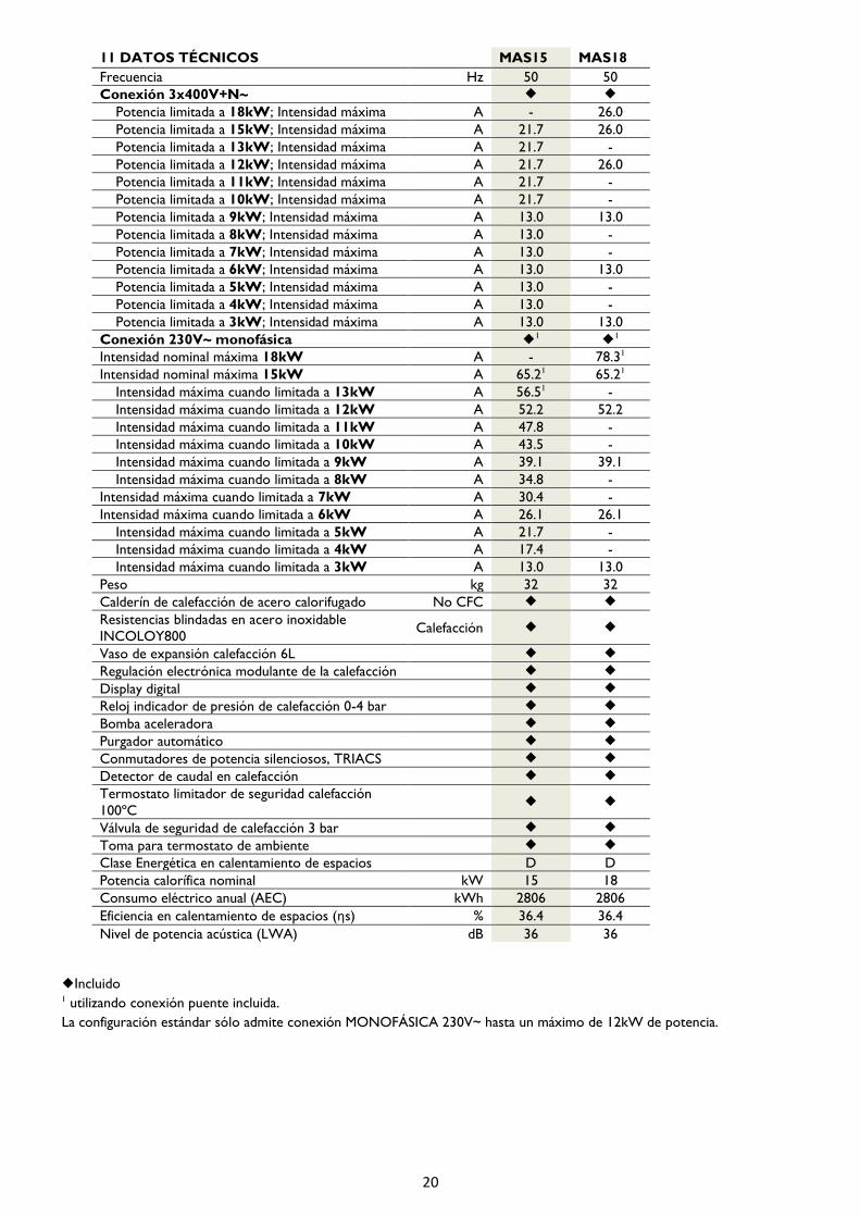
11 DATOS TÉCNICOS MAS15 MAS18
Frecuencia Hz 50 50
Conexión 3x400V+N~
Potencia limitada a 18kW; Intensidad máxima A - 26.0
Potencia limitada a 15kW; Intensidad máxima A 21.7 26.0
Potencia limitada a 13kW; Intensidad máxima A 21.7 -
Potencia limitada a 12kW; Intensidad máxima A 21.7 26.0
Potencia limitada a 11kW; Intensidad máxima A 21.7 -
Potencia limitada a 10kW; Intensidad máxima A 21.7 -
Potencia limitada a 9kW; Intensidad máxima A 13.0 13.0
Potencia limitada a 8kW; Intensidad máxima A 13.0 -
Potencia limitada a 7kW; Intensidad máxima A 13.0 -
Potencia limitada a 6kW; Intensidad máxima A 13.0 13.0
Potencia limitada a 5kW; Intensidad máxima A 13.0 -
Potencia limitada a 4kW; Intensidad máxima A 13.0 -
Potencia limitada a 3kW; Intensidad máxima A 13.0 13.0
Conexión 230V~ monofásica 1
1
Intensidad nominal máxima 18kW A - 78.31
Intensidad nominal máxima 15kW A 65.21 65.21
Intensidad máxima cuando limitada a 13kW A 56.51 -
Intensidad máxima cuando limitada a 12kW A 52.2 52.2
Intensidad máxima cuando limitada a 11kW A 47.8 -
Intensidad máxima cuando limitada a 10kW A 43.5 -
Intensidad máxima cuando limitada a 9kW A 39.1 39.1
Intensidad máxima cuando limitada a 8kW A 34.8 -
Intensidad máxima cuando limitada a 7kW A 30.4 -
Intensidad máxima cuando limitada a 6kW A 26.1 26.1
Intensidad máxima cuando limitada a 5kW A 21.7 -
Intensidad máxima cuando limitada a 4kW A 17.4 -
Intensidad máxima cuando limitada a 3kW A 13.0 13.0
Peso kg 32 32
Calderín de calefacción de acero calorifugado No CFC
Resistencias blindadas en acero inoxidable
INCOLOY800 Calefacción
Vaso de expansión calefacción 6L
Regulación electrónica modulante de la calefacción
Display digital
Reloj indicador de presión de calefacción 0-4 bar
Bomba aceleradora
Purgador automático
Conmutadores de potencia silenciosos, TRIACS
Detector de caudal en calefacción
Termostato limitador de seguridad calefacción
100ºC
Válvula de seguridad de calefacción 3 bar
Toma para termostato de ambiente
Clase Energética en calentamiento de espacios D D
Potencia calorífica nominal kW 15 18
Consumo eléctrico anual (AEC) kWh 2806 2806
Eficiencia en calentamiento de espacios (ηs) % 36.4 36.4
Nivel de potencia acústica (LWA) dB 36 36
Incluido
1 utilizando conexión puente incluida.
La configuración estándar sólo admite conexión MONOFÁSICA 230V~ hasta un máximo de 12kW de potencia.

21
12 ESQUEMAS ELÉCTRICOS

22
INDEX
1 IMPORTANT 23
2 SAFETY 23
3 INTRODUCTION 23
3.1 DESIGN & OPERATION 23
3.2 PRINCIPLE COMPONENTS 2
3.3 KEY TO COMPONENTS 3
3.4 SAFETY DEVICES 3
4 INSTALLATION 3
4.1 GENERAL REQUIREMENTS 4
4.2 UNPACKING & CONTENTS 4
4.3 LOCATION 4
4.4 DIMENSIONS & CONNECTIONS 4
4.5 CLEARANCES 4
4.6 MOUNTING BRACKET 5
4.7 WATER CONNECTIONS 5
4.8 SAFETY VALVE CONNECTIONS 6
4.9 PUMP DUTY 6
4.10 ELECTRICAL CONNECTIONS 6
4.11 ROOM THERMOSTAT CONNECTION 8
4.12 OUTDOOR NTC TEMPERATURE SENSOR
CONNECTION 8
5 COMMISIONING 8
5.1 INSTALLATION PARAMETERS 9
5.2 LIMITING BOILER MAXIMUM OUTPUT 9
5.3 HEATING SYSTEM FLUSHING 10
5.4 HEATING SYSTEM INITIAL FILLING 11
5.5 PUMP CHECKING & VENTING 11
5.6 MORE INSTALLATION DATA 11
6 OPERATING THE BOILER 12
6.1 INITIAL SWITCHING ON 12
6.2 CONTROL PANEL DESCRIPTION 12
6.3 CENTRAL HEATING OPERATION 13
6.4 ANTI-FREEZE MODE 13
6.5 USER PARAMETERS 14
6.6 HEATING MODULATION FEATURE 14
6.7 AUTO HEATING REGULATION 14
6.8 BLOCKING THE CONTROLS 15
6.9 PUMP ANTI-SEIZE FUNCTION 15
7 TROUBLE SHOOTING 16
7.1 POSSIBLE FAULTS & SOLUTIONS 17
7.2 OVERHEAT LOCK-OUT & RE-SETTING 17
7.3 HEATING FLOW SWITCH – E3 ERROR 17
7.4 CHECKING RATED HEAT OUTPUT 17
8 MAIN COMPONENTS LIST 18
9 MAINTENANCE & CARE 18
10 ENVIRONMENTAL INFORMATION 18
11 TECHNICAL DATA 19
12 WIRING DIAGRAMS 20
DECLARATION OF CONFORMITY CE 22

23
1 IMPORTANT
The following installation instructions are intended to guide
the competent person throughout the entire installation
process.
The boiler’s guarantee does not cover any damage caused
by non-observance of any of these instructions.
These installation instructions and user’s guide must be
conserved and given to any new user.
The symbols used in the text are explained below:
WARNING This indication shows the possibility
of causing death from electric shock.
WARNING This indication shows the
possibility of causing death or
serious injury.
CAUTION This indication shows the
possibility of causing injury or
damage to properties only.
Symbol for useful information.
2 SAFETY
o This appliance is not destined for use by anyone
(including children) with reduced physical, sensorial or
mental capacities or those who do not know how to
use the appliance, unless they are supervised or
instructed by a person responsible for their safety.
o Check that the voltage on the indicator plate of the
boiler coincides with the voltage of the mains circuit
to which it is going to be connected.
o The use of these boilers in the presence of gases,
explosives or inflammable objects is prohibited.
o The air inputs and outputs of the boiler ensure its
correct operation and protect it from over-heating.
They must never be covered.
o This boiler must be disconnected from the mains
electricity before carrying out any internal repairs.
o The boiler must be installed in such a manner that the
switches or other controls cannot be touched by
anyone who is using the bath or shower.
o The installation must be performed in accordance with
current electricity regulations.
o This appliance is destined to be permanently
connected to a fixed installation. The power circuit of
the boiler must incorporate an omni-polar cut-off
switch with a separation between the contacts of at
least 3 mm.
o The electricity supply circuit must incorporate a
Residual-Current Device.
o This boiler must be earthed.
o All the models incorporate different safety elements. If
one or more of them are activated, consult the
section 7 TROUBLE SHOOTING.
o In time, the presence in the air of smoke, dust and
pollution may stain the walls and areas close to the
appliance.
o Any improper use is forbidden.
o Do not install the boiler in rooms prone to frost.
3 INTRODUCTION
3.1 DESING & OPERATION
The Gabarrón MATTIRA MAS18 and MAS15 boilers are
electrically heated appliances providing wet central heating
through a standard radiator system (or underfloor system
with special kit).
Outputs are from 2 to 18kW. Maximum output can be
adjusted to match the heat requirement of the system or
the limitations of the incoming available power supply.
Operation is possible on three phase 3x400V+N or single
phase 230V – (Standard configuration allows a maximum of
12kW in single phase mode).
The boilers are designed for internal installation on a
suitable wall with consideration for the total weight of the
appliance when full.
A digital control panel provides user control to adjust the
temperatures of heating. A power modulation feature
automatically adjusts the heating output to the demand to
ensure economic operation. A suitable external time
clock/room thermostat should be fitted (not supplied). All
components for sealed system central heating are built-in.
3.2 PRINCIPLE COMPONENTS
• Insulated steel boiler unit with immersed stainless
steel elements INCOLOY800.
• Fully integrated electronic control boards featuring
temperature control and modulation function, pump
over-run, anti-seize and frost protection. Self-
diagnostic fault information.
• Sealed system heating components: circulating pump,
expansion vessel, auto air-vent, 3 bar relief valve,
pressure gauge, water flow switch and temperature
limit safety thermostat.
• Silent TRIAC power switches.
• Digital control board.
i
24
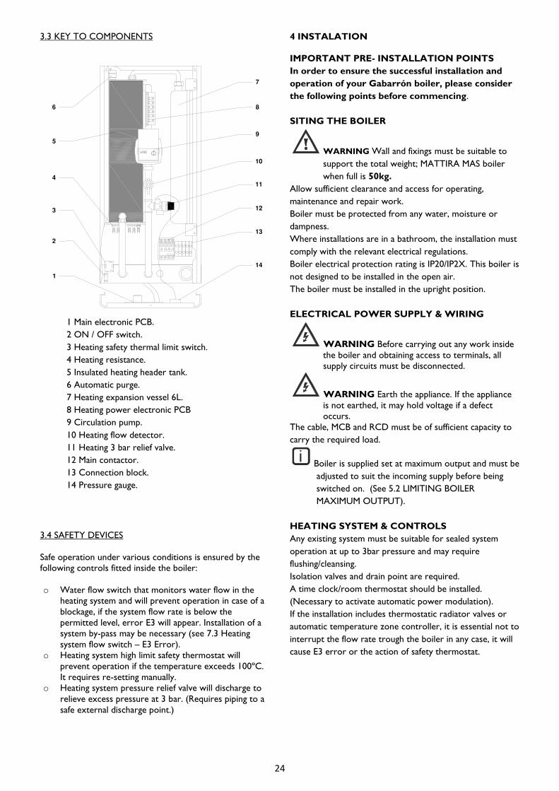
3.3 KEY TO COMPONENTS
1 Main electronic PCB.
2 ON / OFF switch.
3 Heating safety thermal limit switch.
4 Heating resistance.
5 Insulated heating header tank.
6 Automatic purge.
7 Heating expansion vessel 6L.
8 Heating power electronic PCB
9 Circulation pump.
10 Heating flow detector.
11 Heating 3 bar relief valve.
12 Main contactor.
13 Connection block.
14 Pressure gauge.
3.4 SAFETY DEVICES
Safe operation under various conditions is ensured by the
following controls fitted inside the boiler:
o Water flow switch that monitors water flow in the
heating system and will prevent operation in case of a
blockage, if the system flow rate is below the
permitted level, error E3 will appear. Installation of a
system by-pass may be necessary (see 7.3 Heating
system flow switch – E3 Error).
o Heating system high limit safety thermostat will
prevent operation if the temperature exceeds 100ºC.
It requires re-setting manually.
o Heating system pressure relief valve will discharge to
relieve excess pressure at 3 bar. (Requires piping to a
safe external discharge point.)
4 INSTALATION
IMPORTANT PRE- INSTALLATION POINTS
In order to ensure the successful installation and
operation of your Gabarrón boiler, please consider
the following points before commencing.
SITING THE BOILER
WARNING Wall and fixings must be suitable to
support the total weight; MATTIRA MAS boiler
when full is 50kg.
Allow sufficient clearance and access for operating,
maintenance and repair work.
Boiler must be protected from any water, moisture or
dampness.
Where installations are in a bathroom, the installation must
comply with the relevant electrical regulations.
Boiler electrical protection rating is IP20/IP2X. This boiler is
not designed to be installed in the open air.
The boiler must be installed in the upright position.
ELECTRICAL POWER SUPPLY & WIRING
WARNING Before carrying out any work inside
the boiler and obtaining access to terminals, all
supply circuits must be disconnected.
WARNING Earth the appliance. If the appliance
is not earthed, it may hold voltage if a defect
occurs.
The cable, MCB and RCD must be of sufficient capacity to
carry the required load.
Boiler is supplied set at maximum output and must be
adjusted to suit the incoming supply before being
switched on. (See 5.2 LIMITING BOILER
MAXIMUM OUTPUT).
HEATING SYSTEM & CONTROLS
Any existing system must be suitable for sealed system
operation at up to 3bar pressure and may require
flushing/cleansing.
Isolation valves and drain point are required.
A time clock/room thermostat should be installed.
(Necessary to activate automatic power modulation).
If the installation includes thermostatic radiator valves or
automatic temperature zone controller, it is essential not to
interrupt the flow rate trough the boiler in any case, it will
cause E3 error or the action of safety thermostat.
i

25
A Heating FLOW ¾”
B Heating RETURN ¾”
C Safety valve drain
D Electrical connection
4.1 GENERAL REQUIREMENTS
The installation should be carried out by a person certified
as competent for the installation of unvented hot water
systems in accordance with current building regulations.
Installation should also be in accordance with the relevant
Standards and Codes of Practice.
4.2 UNPACKING & CONTENTS
- Wall bracket with
template.
- Boiler.
- Documentation.
- Bag with connecting
links.
Dispose of the cardboard packaging at a cardboard
recycling site. Observe national regulations.
4.3 LOCATION
WARNING: INSTALL UPRIGHT ON A WALL
SUITABLE TO SUPPORT THE TOTAL WEIGHT
OF THE BOILER WHEN FULL OF WATER – 50
kg
The location should be clean and dry with no presence of
gases, explosives or flammable objects.
It is not suitable for installation outside and should be
protected from moisture and frost.
The boiler must be sited so that the boiler and controls are
not accessible to any persons whilst using a bath or shower
and there should be no possibility of water dripping or
splashing onto the boiler or controls.
Electrical safety regulations for clearances must be followed
if installed in a bathroom or shower area.
Where possible the boiler should be sited to minimize the
pipe distance to hot water outlets.
The power supply cable should be carefully routed and
secured and provision made for a suitable isolation switch
and MCB/RCD.
4.4 DIMENSIONS & CONNECTIONS
4.5 CLEARANCES
A: 50 mm B: 10 mm C: 200 mm
The clearances around the boiler as shown above must be
observed for correct operation.
A minimum of 200mm clearance must be maintained
underneath the boiler to allow replacement of the heating
elements if required. A minimum of 500 mm clearance must
be maintained in front of the boiler to enable easy access
for servicing.
Ensure sufficient space to make all water connections
including the outlet pipes for the heating safety valve which
should be routed to a suitable discharge point.
26
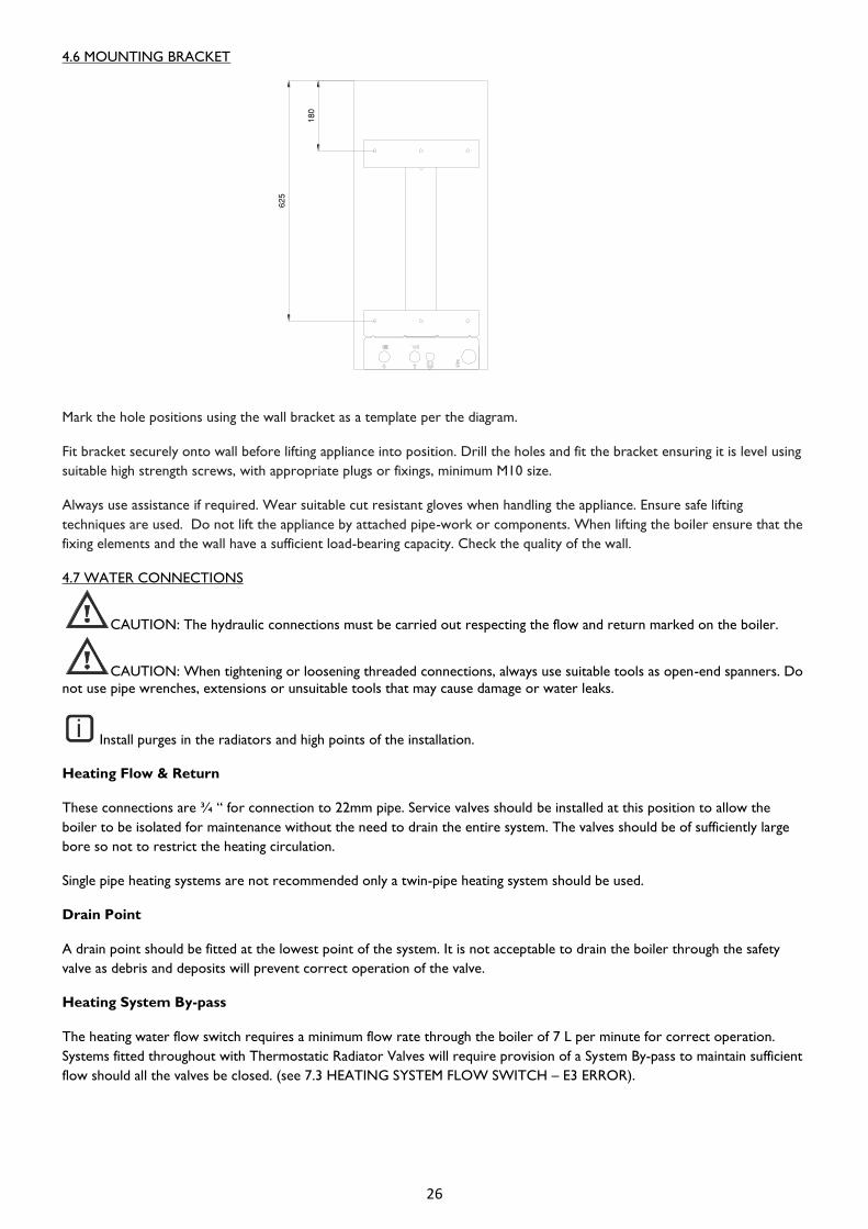
4.6 MOUNTING BRACKET
Mark the hole positions using the wall bracket as a template per the diagram.
Fit bracket securely onto wall before lifting appliance into position. Drill the holes and fit the bracket ensuring it is level using
suitable high strength screws, with appropriate plugs or fixings, minimum M10 size.
Always use assistance if required. Wear suitable cut resistant gloves when handling the appliance. Ensure safe lifting
techniques are used. Do not lift the appliance by attached pipe-work or components. When lifting the boiler ensure that the
fixing elements and the wall have a sufficient load-bearing capacity. Check the quality of the wall.
4.7 WATER CONNECTIONS
CAUTION: The hydraulic connections must be carried out respecting the flow and return marked on the boiler.
CAUTION: When tightening or loosening threaded connections, always use suitable tools as open-end spanners. Do
not use pipe wrenches, extensions or unsuitable tools that may cause damage or water leaks.
Install purges in the radiators and high points of the installation.
Heating Flow & Return
These connections are ¾ “ for connection to 22mm pipe. Service valves should be installed at this position to allow the
boiler to be isolated for maintenance without the need to drain the entire system. The valves should be of sufficiently large
bore so not to restrict the heating circulation.
Single pipe heating systems are not recommended only a twin-pipe heating system should be used.
Drain Point
A drain point should be fitted at the lowest point of the system. It is not acceptable to drain the boiler through the safety
valve as debris and deposits will prevent correct operation of the valve.
Heating System By-pass
The heating water flow switch requires a minimum flow rate through the boiler of 7 L per minute for correct operation.
Systems fitted throughout with Thermostatic Radiator Valves will require provision of a System By-pass to maintain sufficient
flow should all the valves be closed. (see 7.3 HEATING SYSTEM FLOW SWITCH – E3 ERROR).
i

27
System Expansion
An integral 6 L expansion vessel provides for expansion of the heated system water under normal conditions however a
system with larger volumes of water may require extra expansion capacity to be provided.
4.8 SAFETY VALVE CONNECTIONS
The 3 bar pressure relief valve may discharge boiling water and should be piped with a continuous fall to a safe yet visible
point where any discharge cannot cause damage or injury.
CAUTION: The discharge pipe-work from the T&P relief valve must be installed by a competent person.
The discharge pipe material must be capable of conveying water / steam at 100ºC.
All installations must be fitted in accordance with all local regulations in force at that time. Failure to comply with these
regulations will invalidate the manufacturers’ warranty.
4.9 PUMP DUTY
Boiler equipped with a high efficiency circulation pump, with a maximum delivery head of 6.2 m and a maximum flow of 3.3
m³ / h.
There are selectable operation modes with the built-in knob. You can select constant operating speeds I, II and III.
A LED indicator informs about the operating status of the pump:
- Green: correct operation.
- Green / red flashing: Lower voltage U<180V; overvoltage U>253V; Module overheating
- Red flashing: pump blocked.
4.10 ELECTRICAL CONNECTIONS
Connection to Mains Supply
The MAS15 and MAS18 boilers must be installed in premises having a system impedance of not more than 0.25 + j0.25Ω.
The MAS15 and MAS18 boilers comply with the technical requirements of EN 61000-3-3.
The MAS15 and MAS18 boilers must be installed in premises having a service capacity ≥100 A per phase.
Complete all the pipe-work before connecting the boiler to the electricity supply.
Any re-installation must be performed by qualified electricians.
Ensure that the mains voltage available coincides with that shown on the rating label.
WARNING: THE SUPPLY CABLE TO THE BOILER SHOULD BE OF SUFFICIENT SIZE TO CARRY THE LOAD
CAPACITY REQUIRED. IT SHOULD BE WIRED THROUGH A LINKED ISOLATOR SWITCH WITH MINIMUM
CONTACT GAPS OF 3mm IN EVERY POLE AND PROTECTED BY A SUITABLY RATED CIRCUIT BREAKER MCB/RCD
Install the necessary electrical protections as indicated in the current regulations. In the event of these regulations not being
complied with, the manufacturer will not be liable for any bodily injury or material damage that may occur.
WARNING: IT IS ESSENTIAL THAT THE BOILER IS PROPERLY EARTHED and the wiring tested to
current IEE regulations.

28
Electrical Supply Sizing
The following table shows the specification for a boiler installed on three phase single phase 3x400V+N~.
The following table shows the specification for a boiler installed on single phase 230V~ supply.
* The standard configuration of the boiler only allows a maximum of 12kW when connected SINGLE-PHASE 230V~.
Connection to Boiler
WARNING: Touching live connections can cause serious personal injury.
Before establishing a mains connection switch off the power supply. Secure the power supply against being switched on again.
Mains connection terminals remain live even if the on/off switch is turned off.
The boiler is delivered ready for operation on 3x400V three phase supply. For operation on 230V single phase the bridging
connection supplied must be connected across the terminals of the connection block as shown.
The terminal connection block is accessed after removing the boiler front panel . The supply cable should be safely routed to
this point through the cable entry point on the right hand bottom of the boiler.
CAUTION: A mains voltage at the incorrect plug terminal can destroy the electronics.
Make sure the connectin cables are securely fastened to the plug terminals.
i
Rated output of boiler 4kW 5kW 6kW 7kW 8kW 9kW 10kW 11kW 12kW 13kW 15kW 18kW
Supply current 13.0A 13.0A 13.0A 13.0A 13.0A 13.0A 21.7A 21.7A 21.7A 21.7 21.7A 26.0A
RCD rating 16A 16A 16A 16A 16A 16A 25A 25A 25A 25A 25A 32A
Minimum cable size 4mm 4mm 4mm 4mm 4mm 4mm 6mm 6mm 6mm 6mm 6mm 10mm
Rated output of boiler 4kW 5kW 6kW 7kW 8kW 9kW 10kW 11kW 12kW 13kW 15kW 18kW
Supply current 17.4A 21.7A 26.1A 30.4A 34.8A 39.1A 43.5A 47.8A 52.2A 56.5A* 65.2A* 78.3A*
RCD rating 20A 25A 32A 32A 40A 50A 50A 50A 63A 63A* 80A* 80A*
Minimum cable size 4mm 6mm 10mm 10mm 10mm 16mm 16mm 16mm 16mm 25mm 25mm 35mm

29
Wiring External Controls
It is recommended that the boiler is controlled by an external control such as a time clock or room thermostat or a
combined programmable room thermostat such as the Gabarrónmodel CTP-10.
CAUTION: The switching connection of this control should be VOLT FREE and connected to the terminals
indicated ‘TA’ on the PCB. The factory fitted link across these terminals must be removed.
The boiler’s automatic power modulation feature is activated by the initial interruption of this switching link.
4.11 ROOM THERMOSTAT CONNECTION
A ‘volt free’ room thermostat can be connected to regulate heating installation. To take advantage of the modulation
feature of MAS Boiler, the use of a room thermostat is required.
Connect the room thermostat across the terminals marked ‘TA’ on the PCB. See “12 WIRING DIAGRAMS”.
4.12 OUTDOOR NTC TEMPERATURE SENSOR CONNECTION
An outdoor temperature sensor must be fitted to the boiler to activate the auto heating regulation depending on the
outdoors temperature.
Connect a NTC sensor (10kΩ - 25ºC) across the terminals marked T.EXT on the PDC. See “12 WIRING DIAGRAMS”.
5 COMISSIONING
5.1 INSTALLATION PARAMETERS
These parameters must be adjusted by the installer to match the requirements of the installation.
To access to installation parameters menu – with front display OFF, press and hold the and buttons together for at
least 5 seconds.
To move forward or backward through the menu use the and buttons respectively.
To modify a parameter, press the button to display the current setting, modify the setting as required using the and
buttons. To confirm the new setting, press the button once.
After setting the various parameters it is necessary to validate by pressing the button for 3 seconds. If none of the
buttons are pressed for 30 seconds, the installation parameter menu will be automatically closed without validating/saving any
changes.

30
Boiler type. For MAS18 and MAS15 boilers, this parameter is 0.
Model. 18 corresponds to model MAS18, 15 corresponds to model MAS15.
Boiler maximum output limit.
Model MAS18 can be limited to 18 - 15 - 12 - 9 - 6 - 3 kW.
Model MAS15 can be limited to 15 - 13 - 12 - 11 - 10 - 9 - 8 - 7 - 6 - 5 - 4 - 3 - 2 kW.
Underfloor heating. If the boiler is underfloor heating ready this parameter will be 1 (an especial limiter
is required), otherwise it will be 0.
Outdoor temperature probe. An outdoor temperature probe (not provided) can be installed. In this
case the parameter value will be 1.
Heating temperature differential. The heating temperature differential can be selected from 2ºC to
10ºC. The default value is 2ºC.
Modulation. Possible values: 1 (modulation ON), 0 (modulation OFF).
Units. It is possible to change temperature units (ºC Celsius, ºF Fahrenheit). Default value: ºC.
AUTO heating regulation. If a fan outdoor temperature probe is installed it is possible to activate the
auto heating regulation by shifting this parameter value to 1.
TIMAX. Maximum water flow temperature in AUTO heating mode.
TIMIN. Minimum water flow temperature in AUTO heating mode.
TEMAX. Outdoor temperature from which the water flow temperature will be TIMIN.
TEMIN. Outdoor temperature below which the water flow temperature will be TIMAX.
5.2 LIMITING BOILER MAXIMUM OUTPUT
The boiler is supplied for operation on maximum heat output of 15kW or 18 kW depending of the model. The output can
be rated below this maximum to match the heat load required. The setting is realized modifying P03 parameter. See “5.1.
INSTALLATIONS PARAMETERS”.
WARNING: ON INSTALLATIONS WHERE THE INCOMING POWER SUPPLY IS NOT CAPABLE OF
MAXIMUM LOAD THE BOILER CONTROL MUST BE RE-CONFIGURED TO LIMIT THE OUTPUT BEFORE SWITCHING
ON.
The boiler will not exceed this pre-set maximum but will still modulate in heating mode up to this level, adapting to demand
and ensuring economic operation.
Correct configuration for the selected output can be checked on the boiler display panel following the procedure shown in
“7.4 CHECKING RATED HEAT OUTPUT”.
31
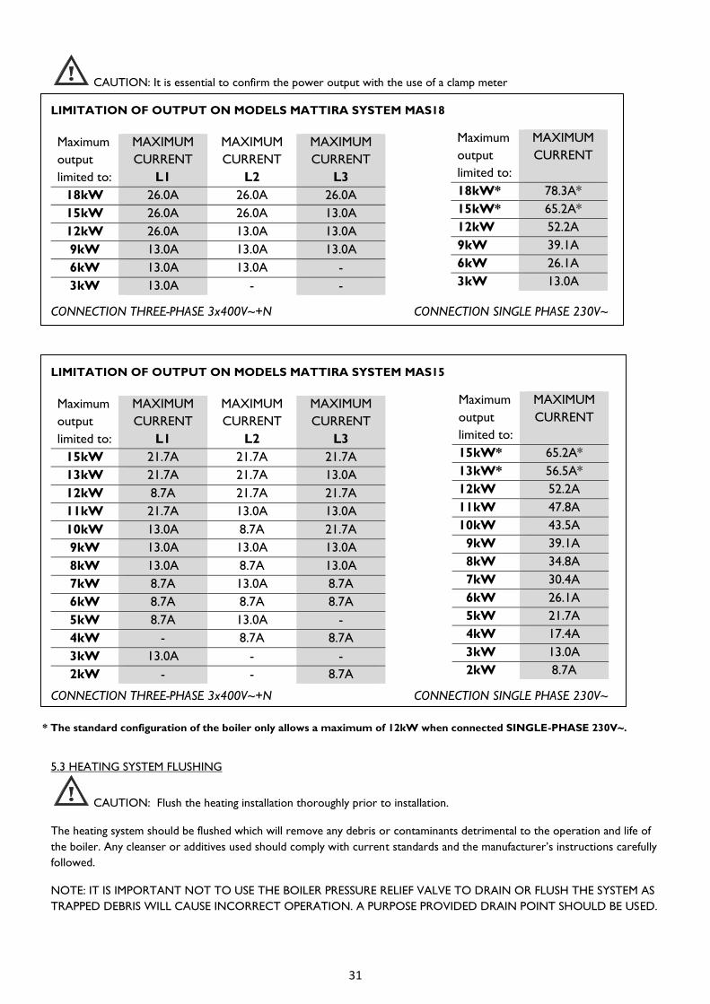
CAUTION: It is essential to confirm the power output with the use of a clamp meter
LIMITATION OF OUTPUT ON MODELS MATTIRA SYSTEM MAS18
CONNECTION THREE-PHASE 3x400V~+N CONNECTION SINGLE PHASE 230V~
LIMITATION OF OUTPUT ON MODELS MATTIRA SYSTEM MAS15
CONNECTION THREE-PHASE 3x400V~+N CONNECTION SINGLE PHASE 230V~
* The standard configuration of the boiler only allows a maximum of 12kW when connected SINGLE-PHASE 230V~.
5.3 HEATING SYSTEM FLUSHING
CAUTION: Flush the heating installation thoroughly prior to installation.
The heating system should be flushed which will remove any debris or contaminants detrimental to the operation and life of
the boiler. Any cleanser or additives used should comply with current standards and the manufacturer’s instructions carefully
followed.
NOTE: IT IS IMPORTANT NOT TO USE THE BOILER PRESSURE RELIEF VALVE TO DRAIN OR FLUSH THE SYSTEM AS
TRAPPED DEBRIS WILL CAUSE INCORRECT OPERATION. A PURPOSE PROVIDED DRAIN POINT SHOULD BE USED.
Maximum
output
limited to:
MAXIMUM
CURRENT
L1
MAXIMUM
CURRENT
L2
MAXIMUM
CURRENT
L3
18kW 26.0A 26.0A 26.0A
15kW 26.0A 26.0A 13.0A
12kW 26.0A 13.0A 13.0A
9kW 13.0A 13.0A 13.0A
6kW 13.0A 13.0A -
3kW 13.0A - -
Maximum
output
limited to:
MAXIMUM
CURRENT
18kW* 78.3A*
15kW* 65.2A*
12kW 52.2A
9kW 39.1A
6kW 26.1A
3kW 13.0A
Maximum
output
limited to:
MAXIMUM
CURRENT
L1
MAXIMUM
CURRENT
L2
MAXIMUM
CURRENT
L3
15kW 21.7A 21.7A 21.7A
13kW 21.7A 21.7A 13.0A
12kW 8.7A 21.7A 21.7A
11kW 21.7A 13.0A 13.0A
10kW 13.0A 8.7A 21.7A
9kW 13.0A 13.0A 13.0A
8kW 13.0A 8.7A 13.0A
7kW 8.7A 13.0A 8.7A
6kW 8.7A 8.7A 8.7A
5kW 8.7A 13.0A -
4kW - 8.7A 8.7A
3kW 13.0A - -
2kW - - 8.7A
Maximum
output
limited to:
MAXIMUM
CURRENT
15kW* 65.2A*
13kW* 56.5A*
12kW 52.2A
11kW 47.8A
10kW 43.5A
9kW 39.1A
8kW 34.8A
7kW 30.4A
6kW 26.1A
5kW 21.7A
4kW 17.4A
3kW 13.0A
2kW 8.7A

32
5.4 HEATING SYSTEM INITIAL FILLING
Ensure both flow and return isolation valves are open. Identify the boiler automatic air release valve at the top right hand
side of boiler and loosen the cap. Close any manual air vents fitted on the system.
Be careful not to splash any of the electrical components.
Fill slowly until the pressure gauge indicates between 1 and 1.5 bar.
Proceed to vent all the manual release valves until all air is purged from the system. It will be necessary to top-up through
the filling during this operation, filling the installation until the pressure gauge indicates between 1 and 1.5 bar.
5.5 PUMP CHECKING & VENTING
Sometimes (i.e. if display fault E3) it is necessary to check that the pump is properly vented and spinning freely.
To purge the pump, turn on the boiler and with the pump selector, alternate between positions III and Min every fifteen
seconds. Keep this operation for 5 minutes.
If excess air remains in the system or there is insufficient pressure or flow rate the boiler will fail to operate and display fault
E3.
A LED indicator informs about the operating status of the pump:
- Green: correct operation.
- Green / red flashing: Lower voltage U<180V; overvoltage U>253V; Module overheating
- Red flashing: pump blocked.
5.6 MORE INSTALLATION DATA
It is possible to display more installation data by pressing for a few seconds and then or .
Heating return temperature.
Maximum output limitation in kW.
Modulated output in kW.
Outdoors temperature. (Only if the sensor is connected and P005 is activated).

33
6 OPERATING THE BOILER
6.1 INITIAL SWITCHING ON
CAUTION: THE MAXIMUM HEAT OUTPUT MUST BE ADJUSTED BEFORE SWITCHING ON. THE BOILER
SHOULD NEVER BE SWITCHED ON WITH THE HEATING SYSTEM TANK EMPTY. DAMAGE
COULD OCCUR.
When the boiler is first connected, it will perform a general self-check and if a fault is detected it will be indicated on
the display.
Turn on the boiler with the on/off switch located at the back of the
boiler as shown.
6.2 CONTROL PANEL DESCRIPTION
Push the button to start the boiler up. The same button will turn the boiler off when pushed again.
If the heating function is not selected the screen will not display a value but just a red dot.
6.3 CENTRAL HEATING OPERATION
First ensure that any external controls such as room thermostat or time clock are demanding heat.
To select the heating function, push the button. Pushing again will switch the function
off and return display to just a red dot.
i
Increases
heating water
temperature
Heating water
temp. and other
messages
Keyboard power ON/ OFF
block ON/OFF
Block / Unblock
Power ON/OFF heating
key
Red dot shows
heating elements
on duty
Decreases
heating water
temperature

34
When the heating mode is selected, the display will show the temperature of
the heating water.
We can modify the setting of the temperature of the water by pushing either the button or the button and using
the same buttons to adjust the value that flashes on the display. The modified setting will be stored after a few seconds or
instantly by pushing the button.
The heating setting can be varied between 8ºC and 85°C.
The symbol H appears after the 85 value or before the 8 value. If this value is selected, the heating will function in anti-freeze
mode.
If the setting is higher than the actual temperature of the heating water, the
heating will connect and a small red indicator of the consumption of heating
resistances will light up.
6.4 ANTI-FREEZE MODE (Frost Protection)
It is possible to select an anti-freeze mode for frost protection during periods of inactivity. The power supply to the boiler
must be maintained.
By attempting to set a central heating temperature below the 8ºC value or above the 85ºC value the symbol H will appear on
the display. By selecting this value, the heating will only work in anti-freeze mode i.e. if the boiler temperature falls to 7ºC the
heating will activate automatically.
6.5 USER PARAMETERS.
The user can change a number of parameters to set some functions of the boiler to the needs of each customer.
To access the user parameters menu – with front display OFF, press and hold the and buttons for at least 5
seconds.
To move forward or backward through the menu use the and buttons respectively.
To modify a parameter, press the button and the current value will be displayed. It can be modified with the and
buttons. Press the button to validate.
Modulation. Possible values: 1 (modulation ON), 0 (modulation OFF).
Units. It is possible to change temperature units (ºC Celsius, ºF Fahrenheit). Default value: ºC.
AUTO heating regulation. If a fan outdoor temperature probe is installed it is possible to activate the
auto heating regulation by shifting this parameter value to 1. Only shown when P05 is activated.
TIMAX. Maximum water flow temperature in AUTO heating mode. Only shown when P05 is activated.
TIMIN. Minimum water flow temperature in AUTO heating mode. Only shown when P05 is activated.
TEMAX. Outdoor temperature from which the water flow temperature will be TIMIN. Only shown when
P05 is activated.
TEMIN. Outdoor temperature below which the water flow temperature will be TIMAX. Only shown
when P05 is activated.

35
6.6 HEATING MODULATION FEATURE
The advanced control board on the boiler will automatically modulate the heating output to the demand required to save
energy.
This function works by the boiler ‘learning’ and anticipating the time taken to reach the temperature level demanded by the
external thermostatic control. The power output is automatically adjusted therefore reducing power consumption on
warmer days or when another heat source is present.
An external ‘volt free’ control must be fitted across the terminals marked ‘TA’ on the PCB and the ‘bridge’ removed for this
function to be activated.
This feature can be disabled using parameter P08. See “6.5 USER PARAMETERS”.
6.7 AUTO HEATING REGULATION.
It is possible to regulate the temperature at which the boiler drives the water heating circuit depending on the outdoors
temperature. This method of regulation provides maximum comfort as it anticipates changes in the thermal needs of the
house. The room thermostat continues to regulate the temperature inside the house.
To activate this mode of heating, the installer will need to connect an external temperature sensor (not supplied) and
activate the P05 and P11 parameters.
There are four parameters that define this function.
TIMAX. Maximum water flow temperature in AUTO heating mode.
In the above example TIMAX=80ºC.
TIMIN. Minimum water flow temperature in AUTO heating mode.
In the above example TIMIN=20ºC.
TEMAX. Outdoor temperature from which the water flow temperature will be TIMIN.
In the above example TEMAX=15ºC.
TEMIN. Outdoor temperature below which the water flow temperature will be TIMAX.
In the above example TEMIN=2ºC.
On the coldest days, the water will be driven at higher temperatures and vice versa on the hottest days-less water will be
driven at a lower temperature. In the example we see how, if the outdoors temperature is of 5ºC the water flow
temperature heating circuit would be about 66 °C.

36
You can temporarily override the automatically calculated set point. If, for example, you want to use the boiler to the
maximum for a few hours even when automatic control mode, you would proceed as follows:
When pressing the or button, the display will alternatively show the calculated set point and the indication
. By holding down either of these two keys for at least 5 seconds, the calculated set point will start flashing and
the set point can now be modified with the same keys. Validate the selection by pressing the button. The time that the
set point is going to be overridden is shown: . It can be modified from 1 to 24h.
Validate the selection by pressing the button. The override set point and the time remaining are displayed alternatively
every 10 seconds. At any time, it is possible to cancel this state just by turning off and restarting the boiler
6.8 BLOCKING THE CONTROLS
It is possible to lock the buttons of the control panel to prevent any adjustment.
By keeping the button pressed down for a few seconds, the control panel will be locked.
The control buttons of the boiler will be locked and no button will respond when pressed. Internally all the settings remain
the same and the boiler will function normally.
To unlock the buttons, press the same button down for a few seconds until the above displayed symbol goes off. If the boiler
is disconnected from the mains or there is a failure in the house’s electricity supply, the buttons will also be unlocked.
6.9 PUMP ANTI-SEIZE FUNCTION
The advanced boiler control will automatically energize the pump for 10 seconds each month to protect it from seizing
during long periods of inactivity. The power supply must be maintained for this function to operate.

37
7 TROUBLESHOOTING
7.1 POSSIBLE FAULTS & SOLUTIONS
Problem Possible cause Solution
Boiler will not start
No power to boiler. Check incoming power supply.
No power. Check boiler control switch is on. (See
Section 6.1.)
Heating overheat. Switch tripped. Locate switch and reset. (See Section 7.2)
Fault E1 displayed
Heating flow temperature sensor
Heating water out temperature
probe defective.
Contact Technical Service
Fault E2 displayed
Heating return temperature sensor
Heating water return
temperature probe defective.
Contact Technical Service
Fault E3 displayed
Heating system water flow switch
Low heating system pressure. Check for leaks.
Refill heating system to 1.5 bar.
Pump not turning. Check rotating freely (sect 5.5)
Replace pump if necessary.
Air in system. Purge thoroughly.
Check automatic air valve open.
Vent pump (sect 5.5)
System resistance too high or
blockage.
Check pump speed 3.
Check pump duty (sect 4.9)
Open all radiator valves.
Install system by-pass.
Fault E8 displayed
Outdoor temperature sensor
Defective outdoor temperature
sensor or not present.
This sensor is optional. Check
connections. Replace sensor if necessary.
Heating system water
discharging from 3 bar safety
valve
Excessive heating system
pressure.
Check filling loop not passing and remove.
Check expansion vessel is charged to
correct level with air.
Check system expansion volume.
The buttons do not respond Control panel blocked See Section 6.8 BLOCKING THE
CONTROLS
Low heating temperature
Settings too low. Check temperature & output selected.
Failure of heating elements Check and replace.
Heat requirements miscalculated. Re-calculate & configure. If the suggested action fails to resolve a problem, please contact ELNUR technical service for further advice.
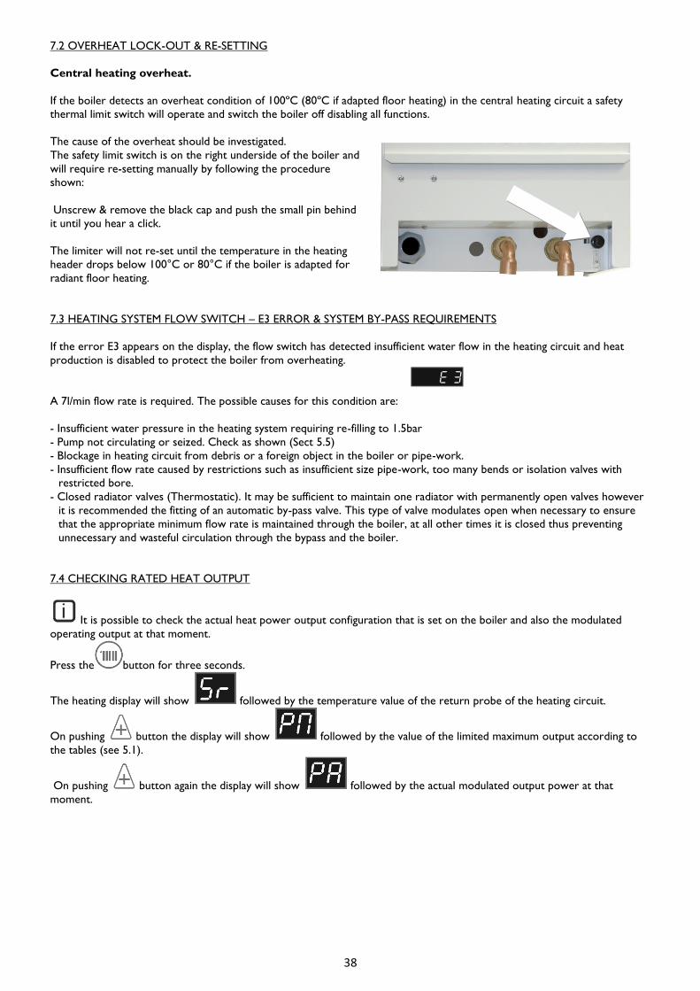
38
7.2 OVERHEAT LOCK-OUT & RE-SETTING
Central heating overheat.
If the boiler detects an overheat condition of 100ºC (80ºC if adapted floor heating) in the central heating circuit a safety
thermal limit switch will operate and switch the boiler off disabling all functions.
The cause of the overheat should be investigated.
The safety limit switch is on the right underside of the boiler and
will require re-setting manually by following the procedure
shown:
Unscrew & remove the black cap and push the small pin behind
it until you hear a click.
The limiter will not re-set until the temperature in the heating
header drops below 100°C or 80°C if the boiler is adapted for
radiant floor heating.
7.3 HEATING SYSTEM FLOW SWITCH – E3 ERROR & SYSTEM BY-PASS REQUIREMENTS
If the error E3 appears on the display, the flow switch has detected insufficient water flow in the heating circuit and heat
production is disabled to protect the boiler from overheating.
A 7l/min flow rate is required. The possible causes for this condition are:
- Insufficient water pressure in the heating system requiring re-filling to 1.5bar
- Pump not circulating or seized. Check as shown (Sect 5.5)
- Blockage in heating circuit from debris or a foreign object in the boiler or pipe-work.
- Insufficient flow rate caused by restrictions such as insufficient size pipe-work, too many bends or isolation valves with
restricted bore.
- Closed radiator valves (Thermostatic). It may be sufficient to maintain one radiator with permanently open valves however
it is recommended the fitting of an automatic by-pass valve. This type of valve modulates open when necessary to ensure
that the appropriate minimum flow rate is maintained through the boiler, at all other times it is closed thus preventing
unnecessary and wasteful circulation through the bypass and the boiler.
7.4 CHECKING RATED HEAT OUTPUT
It is possible to check the actual heat power output configuration that is set on the boiler and also the modulated
operating output at that moment.
Press the button for three seconds.
The heating display will show followed by the temperature value of the return probe of the heating circuit.
On pushing button the display will show followed by the value of the limited maximum output according to
the tables (see 5.1).
On pushing button again the display will show followed by the actual modulated output power at that
moment.
i

39
8 MAIN COMPONENTS
9 MAINTENANCE & CARE
Gabarrón electric boilers do not require any special maintenance for a prolonged and trouble-free life however the following
points should be observed.
- Check and maintain the heating system pressure between 1 & 1.5 bar when cold. Frequent re-filling of the system could
cause scaling and corrosion and should be avoided. Regular pressure loss could indicate a leak and should be investigated
promptly.
CAUTION: Under no circumstances should the boiler be switched on when the system is dry.
- Keep the ventilation openings on the boiler clear to ensure correct operation and protect from overheating. Do not place
or store objects on the boiler.
- Protect against freezing by ensuring power is maintained to the boiler at all times. In dwellings frequently un-occupied or at
risk of freezing an appropriate anti-freeze can be added to the heating system at a concentration of not more than 30% by
volume. Otherwise it is recommended to isolate the power and completely drain the heating and hot water systems.
- The outer case can be cleaned with a damp cloth having first isolated the boiler from the mains. Do not use solvents or
abrasive cleaners.
10 ENVIRONMENTAL INFORMATION
Gabarrón boilers are manufactured within a certified environmental management system. From the design stage, all the
production phases are performed taking into account the most rigorous environmental requirements. For example, the
selection of materials involves guaranteeing their biodegradability, re-use and recycling.
When this boiler’s long, useful life is over; it must be handed in to an electrical equipment collection point for proper
recycling. By ensuring that this product is correctly disposed of, you will help to avoid any possible negative effects on the
environment and public health that could occur if this product is not properly handled. To obtain more detailed information
on the recycling of this product, contact your local authority, your waste disposal service or the shop where you purchased
the product.
These regulations only apply in EU member countries.
Heating expansion vessel 6L ref. 60091510
Insulated heating header tank ref. 60101700
Circulation pump RKC130 ref. 60190076
Power PCB MAC with support ref. 60105595
Heating PCB ref. 60105590
Temperature sensor white ref. 60105600
Temperature sensor black ref. 60105605
15 kW heating resistance & joint 140 ref. 60100750
18 kW heating resistance & joint 140 ref. 60100760
¾” heating flow detector ref. 60100805
0-4 bar pressure gauge ref. 60100820
100°C thermal limiter ref. 60101860
Automatic purge ref. 60091280
3 bar central heating relief valve ref. 60100840
Keyboard MAC ref. 60105555

40
11 TECHNICAL DATA MAS15 MAS18
Frequency Hz 50 50
Connection 3x400V+N~
Output limited to 18kW; Maximum intensity A - 26.0
Output limited to 15kW; Maximum intensity A 21.7 26.0
Output limited to 13kW; Maximum intensity A 21.7 -
Output limited to 12kW; Maximum intensity A 21.7 26.0
Output limited to 11kW; Maximum intensity A 21.7 -
Output limited to 10kW; Maximum intensity A 21.7 -
Output limited to 9kW; Maximum intensity A 13.0 13.0
Output limited to 8kW; Maximum intensity A 13.0 -
Output limited to 7kW; Maximum intensity A 13.0 -
Output limited to 6kW; Maximum intensity A 13.0 13.0
Output limited to 5kW; Maximum intensity A 13.0 -
Output limited to 4kW; Maximum intensity A 13.0 -
Output limited to 3kW; Maximum intensity A 13.0 13.0
Connection 230V~ single phase 1
1
Nominal maximum intensity 18kW A - 78.31
Nominal maximum intensity 15kW A 65.21 65.21
Maximum converted intensity at 13kW A 56.51 -
Maximum converted intensity at 12kW A 52.2 52.2
Maximum converted intensity at 11kW A 47.8 -
Maximum converted intensity at 10kW A 43.5 -
Maximum converted intensity at 9kW A 39.1 39.1
Maximum converted intensity at 8kW A 34.8 -
Maximum converted intensity at 7kW A 30.4 -
Maximum converted intensity at 6kW A 26.1 26.1
Maximum converted intensity at 5kW A 21.7 -
Maximum converted intensity at 4kW A 17.4 -
Maximum converted intensity at 3kW A 13.0 13.0
Weight kg 32 32
Insulated steel heater header No CFC
Stainless steel plated resistance elements
INCOLOY800 Heating
6 L expansion vessel
Electronic regulation of heater modulation
Digital display
0-4 bar pressure gauge
Accelerator pump
Automatic purge
TRIACS silent power switches
Heating flow detector
100°C heating temperature limiter
3 bar heating relief valve
Ambient thermostat intake
Space heating energy efficiency class D D
Rated heat output kW 15 18
Annual electricity consumption (AEC) kWh 2806 2806
Space heating energy efficiency (ηs) % 36.4 36.4
Sound power level (LWA) dB 36 36
included 1 using connecting bridge included.
The standard configuration of the boiler only allows a maximum of 12kW when connected SINGLE-PHASE 230V~.

41
12 WIRING DIAGRAMS

42
NOTAS / NOTES

43
DECLARACION DE CONFORMIDAD De acuerdo con la norma ISO / IEC 17050-1
DECLARATION OF CONFORMITY According to the Standard ISO / IEC 17050-1
Nº 6610000
Nombre del fabricante : ELNUR, S.A.
Manufacturer’s name :
Dirección del fabricante : ELNUR, S.A.
Manufacturer’s address : Travesía de Villa Esther, 11
28110 Algete, Madrid, Spain
Declara que el producto : Caldera modulante digital sólo calefacción “MAS”
Declares, that the product : “MAS” Heating digital modulating boiler
Marca : GABARRÓN
Trade Mark :
Modelos : MAS15, MAS18
Models :
ha sido fabricado conforme a las especificaciones técnicas del producto y cumple en todo
las Normas vigentes, en particular:
has been manufactured to the technical specifications of the product and conforms in all
respects to the relevant standards and regulations in force and especially to :
Seguridad : EN 60335-1:2012+A11:2014
Safety : EN 60335-2-35:2002+A1:2007+A2:2011
EN 50106:2008
EMC : EN 55014-1:2006+A1:2009+A2:2011
EN 55014-2:1997+A1:2001+A2:2008
EN 61000-3-2:2006+A1:2009+A2:2009
EN 61000-3-3:2008
Información adicional :
Additional information :
El producto aquí citado lleva el marcado CE y se halla en conformidad con la Directiva de Ecodiseño
2009/125/CE, la Directiva de Baja Tensión 2014/35/UE y la Directiva de EMC 2014/30/UE.
Cualquier uso que no esté de acuerdo con las instrucciones y/o cualquier cambio al aparato invalidarán
esta declaración de conformidad.
The product herewith carries the CE mark and complies with the requirements of Ecodesign Directive
2009/125/EC, the Low Voltage Directive 2014/35/UE and EMC Directive 2014/30/UE.
Any use not according to the instructions and/or any change to the appliance will invalidate this declaration of
conformity.
Algete, 28 de Octubre de 2016
Place, Date
Alberto Fernández
Director Gerente
ELNUR, S.A.

Fabricado por / Manufactured by
ELNUR S.A.
Travesía de Villa Esther, 11
28110 Algete - Madrid
+34 91 628 1440
www.elnur.es
www.elnur-global.com
www.elnur.co.uk
Como parte de la política de mejora continua, Elnur s.a. se reserva el derecho a realizar modificaciones técnicas sin previo aviso.
As a part of the policy of continuous product improvement, Elnur s.a reserves the right to alter specifications without notice.
60104006 R4
El símbolo en el producto o en su embalaje indica que este producto no se puede tratar como desperdicios
normales del hogar. Este producto se debe entregar al punto de recolección de equipos eléctricos y
electrónicos para reciclaje. Al asegurarse de que este producto se deseche correctamente usted ayudará a
evitar posibles consecuencias negativas para el ambiente y la salud pública, lo cual podría ocurrir si este
producto no se manipula de forma adecuada. Para obtener información más detallada sobre el reciclaje de
este producto, póngase en contacto con la administración de su ciudad, con su servicio de desechos del hogar
o con la tienda donde compró el producto. Estas disposiciones solamente son válidas en los países miembros
de la UE
The symbol on the product or in its packaging indicates that this product may not be treated as household
waste. Instead it shall be handed over to the applicable collection point for the recycling of electrical and
electronic equipment. By ensuring this product is disposed of correctly, you will help prevent potential
negative consequences for the environment and human health, which could otherwise be caused by
inappropriate waste handling of this product. For more detailed information about recycling of this product,
please contact your local city office, your household waste disposal service or the shop where you purchased
the product. These instructions are only valid in the EU member states.