instantaneous oil-fired water heater installation … heaters/name begins...instantaneous oil-fired...
TRANSCRIPT
Instantaneous Oil-Fired Water Heater
Installation Manual
MODEL OM-128HH
CONTENTS
IMPORTANT
THIS APPLIANCE SHOULD BE INSTALLED BY A LICENSED, AUTHORIZED PERSON(S) DUE TO THENECESSITY OF MAKING ELECTRICAL, WATER AND FUEL CONNECTIONS. RETAIN THIS MANUAL FORFUTURE REFERENCE. CHECK LOCAL CODES AND ORDINANCES FOR PERMITTED USE.
CAUTION
THIS WATER HEATER SHALL NOT BE USED FOR COMMERCIAL USE OR FOR ANY PURPOSES OTHERTHAN HOT WATER SUPPLY USES. OTHER USAGE MAY CAUSE A MALFUNCTION OR SHORTEN ITSSERVICE LIFE. DO NOT REMOVE THE RATING PLATE AND LABELS FROM THE WATER HEATER UNIT.
SECTION A:Safety Tips for Installation ⋯⋯⋯⋯⋯⋯⋯⋯⋯⋯ 1
SECTION B:Unpacking ⋯⋯⋯⋯⋯⋯⋯⋯⋯⋯⋯⋯⋯⋯⋯⋯⋯ 2Standard Installation Parts ⋯⋯⋯⋯⋯⋯⋯⋯⋯⋯ 2Accessory Parts (Option)⋯⋯⋯⋯⋯⋯⋯⋯⋯⋯⋯ 2Dimensional Outline⋯⋯⋯⋯⋯⋯⋯⋯⋯⋯⋯⋯⋯ 3
SECTION C:Installation
Selecting a Location ⋯⋯⋯⋯⋯⋯⋯⋯⋯⋯⋯ 4Tools Needed for Installation ⋯⋯⋯⋯⋯⋯⋯ 4Fuel Tank Installation ⋯⋯⋯⋯⋯⋯⋯⋯⋯⋯⋯ 5Removing Air Trap ⋯⋯⋯⋯⋯⋯⋯⋯⋯⋯⋯⋯ 6Temperature and Pressure Relief
Valve Installation ⋯⋯⋯⋯⋯⋯⋯⋯⋯⋯⋯ 6Plumbing ⋯⋯⋯⋯⋯⋯⋯⋯⋯⋯⋯⋯⋯⋯⋯⋯ 7Permanent Wiring Installation ⋯⋯⋯⋯⋯⋯⋯ 9Differential Switch and Dip Switch⋯⋯⋯⋯⋯10Wiring for Circulation Pump ⋯⋯⋯⋯⋯⋯⋯10Wiring for Timer ⋯⋯⋯⋯⋯⋯⋯⋯⋯⋯⋯⋯⋯11Installation of Unit and Flue Pipe ⋯⋯⋯⋯⋯ 12
SECTION D:Test Run
Preparation ⋯⋯⋯⋯⋯⋯⋯⋯⋯⋯⋯⋯⋯⋯⋯ 15Operation ⋯⋯⋯⋯⋯⋯⋯⋯⋯⋯⋯⋯⋯⋯⋯⋯ 15
SECTION E:Chimney Installation ⋯⋯⋯⋯⋯⋯⋯⋯⋯⋯⋯⋯ 16
OM-128HH_In_US.qxd 14.3.7 13:22 ページ b
BE SURE TO FOLLOW THE FOLLOWING INSTRUCTIONS.
The instructions which are contained in this manual are classified into the following two types, which are"WARNING" and "CAUTION". These instructions are intended to provide important information for safeoperation.
"WARNING" indicates the possibility of causing the user a fatal accident or serious injury if the water heateris incorrectly operated.
"CAUTION" indicates the possibility of causing the user injuries or material damages if the water heater isincorrectly operated.
WARNING
1. Never use any fuel other than ASTM (AMERICAN SOCIETY FOR TESTING AND MATERIAL) D3699 1-KKerosene, D396 Low Sulfur No. 1 or No. 2 Fuel Oil, or ASTM D975 Ultra Low Sulfur Diesel (ULSD). Youare recommended to use the low sulfur fuel.NEVER USE GASOLINE! Use of such fuels can result in an explosion and/or fire and cause injury.
2. Improper installation, adjustment, modification, or service and maintenance by an unauthorized personmay cause SERIOUS UNIT DAMAGE, BODILY INJURY, HAZARD OR PROPERTY DAMAGE. This unitshould be installed by a licensed, authorized person(s) due to the necessity of making electrical, waterand fuel connections. Refer to the installation manual and the operation and maintenance instructionsfor assistance, or consult your dealer for further information.
3. HAZARD OF ELECTRICAL SHOCK! Before removing any access panels of water heater for service, makesure the electrical supply to the water heater is shut off. Failure to do this may result in HAZARD, SERI-OUS BODILY INJURY, OR PROPERTY DAMAGE.
4. Check and comply with all state, local codes and ANSI Z21.22 that may apply to water heater(s) beforebeginning the installation.
5. This water heater is designed to be used no more than 4,922 FT. (1,500 m) above sea level. When thewater heater is installed with the flue pipe at altitude of higher than 1,640 FT. (500 m) ~ 4,922 FT. (1,500m) above sea level or is installed with the chimney adapter at altitude of higher than 3,280 FT. (1,000 m)~ 4,922 FT. (1,500 m), adjustments are needed.Ask your local dealer.The water heater may have a failure of combustion at a high altitude.
6. RISK OF INDOOR AIR POLLUTION AND FIRE. Be sure the exhaust pipe is properly installed and connect-ed. Aluminum tape provided may be used for sealing exhaust pipe connections.
CAUTION
1. Keep the area around the unit clean and free of flammable materials.
2. RISK OF FIRE AND ELECTRIC SHOCK. Do not apply any excessive force or pressure to the power supplycord. Make sure the plug is free of dust. Be sure plug fits the receptacle securely.
3. Install a temperature and pressure relief valve on the water heater in accordance with local codes andANSI Z21.22. See the page 6 for more details.
4. When No. 2 fuel oil is used in an area where the temperature becomes less than 25˚F (-4˚C), it is recom-mended the use of an additive with the fuel to prevent congealing. Check with a fuel supply companyfor the proper additive and mix.
1
SECTION A:SAFETY TIPS FOR INSTALLATION
OM-128HH_In_US.qxd 14.3.7 13:22 ページ 1

UNPACKING1. Unpack the unit carefully.
2. Check to see if there are any loose screws that may have occurred in transit.
3. Take accessories and the instruction manual out of the carton.
STANDARD INSTALLATION PARTSThe following standard installation kits are available:• Direct or Force Flue venting
Use Flue Pipe Installation Kit (Part# 20476440)• Chimney Venting;
Use Chimney Installation Adapter Kit (Part# 20476430-Dia.5” / #20476415-Dia.4”)
For alternate installation methods, you may need to purchase additional accessories.
ACCESSORY PARTS (OPTION)
Self tapping screw(5pcs.)
Screw(4pcs.)
Pipe fixing bracket (4pcs.)
Extension pipe "A" (2pcs.)Extension pipe "B" (2pcs.)
Nut(4pcs.)
Aluminum tape(2pcs.)
Bent joint (2pcs.)(Part#20476461) EA.
ø2-3/4"(ø70mm)
31-3/4"~57" (805~1450mm)
ø2-13/16"(ø71mm)
ø2-13/16"(ø71mm)
ø2-3/4"(ø70mm)
5-7/8"(150mm)
5-7/8"(150mm) Insulating cloth cover
(2pcs.)(Part#20476455) EA.
33-1/2"(850mm)
(Part#20476491) EA.
EXTENSION PIPE KIT
(Part#20476496)EXTENSION FLUE PIPE
(Part#20476486)
9-1/2”(240mm)
NOTE:This extension fluepipe is for wall thick-ness from 10-5/8 in.(270mm) to 18-1/8in. (460mm). 2
SECTION B:UNPACKING
Inner flange(Part#20476468)
Inner flue pipe (1pc.)(Part#20476401)
Flexible bent joint (1pc.)(Part#20476492)
Flexibleexhaust
pipe (1pc.)
Outer flue pipe (1pc.)
13-3/4"(350mm)
Aluminum tape(w:30mm×500mm)
(1pc.)
Insulatingcloth cover
(Part#20476455) Rubber joint(2pcs.)
(Part#20476475 EA.)
Flange gasket(t:5mm)(2pcs.)
(Part#20476471) EA.
Inlet hoseø3"(ø75mm)
(Part#20476451)
33-1/2"(850mm)
Nut(2pcs.)
Screw(2pcs.)
Self tapping screwfor concrete
(8pcs.)
Self tapping screw(8pcs.)
Hose band(2pcs.)
(Part#20476477) EA.
39-3/8"(1000mm)
9-7/8"(250mm)
10-1/2"(266mm)
Outer flange(Part#20476469)ø3-15/16"
(ø100mm)
ø2-13/16"(ø71mm)
ø2-3/4"(ø70mm)
INTAKE PIPE TOP
EXHAUST PIPEADAPTER
CHIMNEY INSTALLATIONADAPTER KIT
(Part#20476430 - Dia. 5")(Part#20476415 - Dia. 4")
FLUE PIPE INSTALLATION KIT
(Part#20476440)
or
CAUTION: Total length of theextension pipebetween the waterheater and the fluepipe must be nogreater than 10ft.with a total of threebends.
NOTE: When using exhaustpipes always coverthe exhaust pipe withthe insulating clothcover.
K
Coupler for circulation pump(2pcs.)
(Red)
Lead wire forcirculation pump
(1pc.) (4.9ft)
(Black)
Coupler for timer(2pcs.)
(White)
Lead wire fortimer
(1pc.) (4.9ft)
(Yellow)
included with the unit
OM-128HH_In_US.qxd 14.3.7 13:22 ページ 2
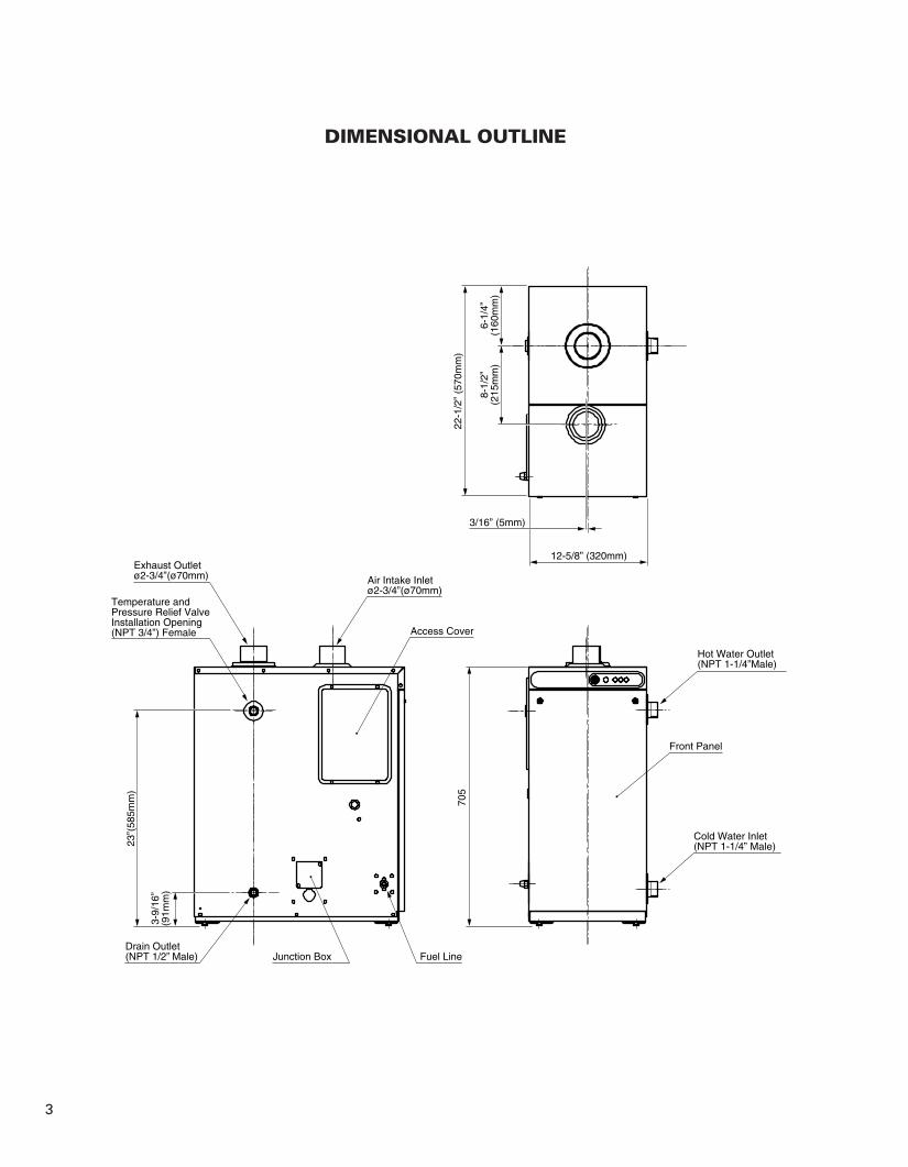
DIMENSIONAL OUTLINE
3
22-1
/2”
(570
mm
)
6-1/
4”(1
60m
m)
8-1/
2”(2
15m
m)
3/16” (5mm)
12-5/8” (320mm)
Access Cover
Air Intake Inletø2-3/4”(ø70mm)
Temperature andPressure Relief ValveInstallation Opening(NPT 3/4”) Female
Exhaust Outletø2-3/4”(ø70mm)
23”(
585m
m)
3-9/
16”
(91m
m)
Fuel LineDrain Outlet(NPT 1/2” Male) Junction Box
Front Panel
Hot Water Outlet(NPT 1-1/4”Male)
Cold Water Inlet(NPT 1-1/4” Male)
705
OM-128HH_In_US.qxd 14.3.7 13:22 ページ 3

4
SECTION C:INSTALLATION
WARNING: This unit must be installed in accordance with these instructions, local codes, ordinances and/orin the absence of local codes, the latest edition of the national fire protection association(NFPA31) code.Check and comply with all state, local codes and ANSI (AMERICAN NATIONAL STANDARDINSTITUTE) Z21.22 that may apply to water heater(s) before beginning the installation.This unit should be installed by a licensed, authorized person(s) due to the necessity of makingelectrical, water and fuel connections.
SELECTING A LOCATION
CAUTION: When No. 2 fuel oil is used in an area where the temperature becomes less than 25˚F (-4˚C), it isrecommended the use of an additive with the fuel to prevent congealing. Check with a fuel supplycompany for the proper additive and mix.
Select a place to install the water heater where water and electric supply are easily available.
1. Select a place which is free of moisture, water spills, pools or snow.
2. Select a place which draining can be done easily.
3. Select a place which the fuel tank can be installed safely.
4. Select a place which is free of combustible substances.
5. The surrounding walls should be finished with noncombustible materials (concrete block, mortar, orplaster are acceptable).
6. The floor on which the water heater is installed must prevent intensive vibrations or shock and must bestrong enough to bear the weight of the water heater.
7. Select a place where proper maintenance and repair can be provided for the unit after installation.
8. Select a place sheltered from weather.
9. Install the unit on a noncombustible surface in a stable position. If installing on combustible floor, theunit should be raised off the floor to prevent contact with combustible materials.
10. Select a place with a suitable environment, which is non-corrosion and non-toxic.
11. Locate the flue pipe termination where it is protected from snow, icing, grass, leaves, loose debrie andstrong wind.
12. Before making a hole in your wall for the flue pipe, make sure the area is free of electrical wires, gaspipes, water pipes, and other obstacles.
TOOLS NEEDED FOR INSTALLATION.
Tool Use
Phillips Head Screwdriver Installation of flue pipe, etc.Electric Drill Drilling hole in wall for flue pipeHole Saw, 4-3/4" diameter Making hole in wall for flue pipePipe Wrench Connecting fuel pipe
OM-128HH_In_US.qxd 14.3.7 13:22 ページ 4

FUEL TANK INSTALLATION
The fuel tank must be purchased separately and installed by a qualified fuel supply technician.
NOTE: Fuel tank installation must comply with National Fire Protection Association Code NFPA 31 or local-ly applicable codes. Check with local building officials.
The following instructions should be followed for installation of a large capacity, gravity-fed fuel tank.¡ Installation height of tank's fuel outlet should be at least 12 in. above floor surface upon which the water
heater rests.¡ To avoid excess fuel pressure to water heater, the top of fuel tank should be no more than 8-1/2 ft. above
the bottom of the unit.¡ The inlet fuel pressure must not exceed 2.5 PSI. If the inlet pressure exceeds 2.5 PSI, a pressure reducer
(Part #10005099) must be used.¡ Fuel tank should be located at least 6 ft. away from all heat sources.¡ 3/8" OD copper tubing should be used for the fuel line.¡ To prevent air locks in the fuel line, the fuel line should be smooth with no inverted U-shaped line or
sharp bends. ¡ Install a UL listed fuel filter at the fuel tank outlet. Shut-off valves should also be installed on the fuel line
and connected to the tank as shown below. Unit should have a separate fuel line from fuel tank.
NOTE: An additional shut-off valve installed next to the exterior wall will minimize the amount of fuel to bedrained should the water heater need to be disconnected. If the valve is inside the building, afusible link type (Part #10005597) is recommended.
1. All external tank must be vented.2. Install a UL listed fuel filter at the fuel tank outlet.
Specifications required of this fuel filter are as follows:Type of Fuel: ASTM D3699 1-K kerosene, ASTM D396 Low Sulfre No. 1 or No. 2 Fuel Oil, or ASTM D975Ultra Low Sulfur Diesel (ULSD)Rated Filtering Capacity: 2 GPH (Minimum)
3. The fuel supply tank must be positioned as to allow gravity feed to the unit and high enough to reducetrapped air in the fuel line. Please refer to Section “D”, page 8 in the Operation and MaintenanceInstructions for the procedure to remove trapped air. (✽)NOTE: If the maximum height is exceeded, a fuel pressure limiting valve is required. Part No.
10005099 has 3/8 in. (N.P.T.) inlet and outlet female openings to accept the fuel line fittings.NOTE: Fusible Link Valve (#10005597)
¡It is most important that the valve, depending on its use, be fully opened or fully closed.¡The top nut on the valve (below the turn handle) is sealed and should never be tightened or
removed.¡When installing fuel lines to the valve, be sure to check for fuel leakage.¡A LEAKING VALVE SHOULD ALWAYS BE REPLACED.
5
Fusible link valve
Shut-off valve
8-1/2 ft. maximum
Tank vent
Outdoor fuel tank
Fuel filter
Shut-off valve
Loop
3/8in. OD copper tubing
(✽) 12 in. minimum
OM-128HH_In_US.qxd 14.3.7 13:22 ページ 5
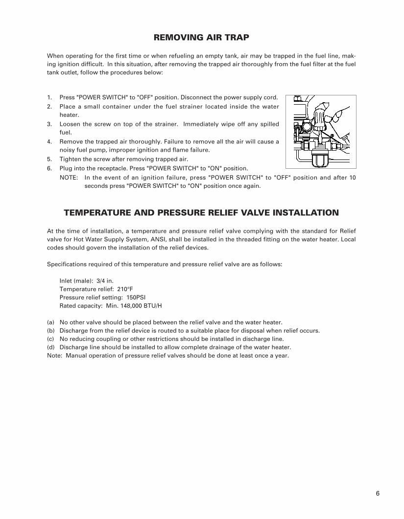
REMOVING AIR TRAP
When operating for the first time or when refueling an empty tank, air may be trapped in the fuel line, mak-ing ignition difficult. In this situation, after removing the trapped air thoroughly from the fuel filter at the fueltank outlet, follow the procedures below:
1. Press "POWER SWITCH" to "OFF" position. Disconnect the power supply cord.
2. Place a small container under the fuel strainer located inside the waterheater.
3. Loosen the screw on top of the strainer. Immediately wipe off any spilledfuel.
4. Remove the trapped air thoroughly. Failure to remove all the air will cause anoisy fuel pump, improper ignition and flame failure.
5. Tighten the screw after removing trapped air.
6. Plug into the receptacle. Press "POWER SWITCH" to "ON" position.
NOTE: In the event of an ignition failure, press "POWER SWITCH" to "OFF" position and after 10seconds press "POWER SWITCH" to "ON" position once again.
TEMPERATURE AND PRESSURE RELIEF VALVE INSTALLATION
At the time of installation, a temperature and pressure relief valve complying with the standard for Reliefvalve for Hot Water Supply System, ANSI, shall be installed in the threaded fitting on the water heater. Localcodes should govern the installation of the relief devices.
Specifications required of this temperature and pressure relief valve are as follows:
Inlet (male): 3/4 in.Temperature relief: 210°FPressure relief setting: 150PSIRated capacity: Min. 148,000 BTU/H
(a) No other valve should be placed between the relief valve and the water heater.(b) Discharge from the relief device is routed to a suitable place for disposal when relief occurs.(c) No reducing coupling or other restrictions should be installed in discharge line.(d) Discharge line should be installed to allow complete drainage of the water heater.Note: Manual operation of pressure relief valves should be done at least once a year.
6
OM-128HH_In_US.qxd 14.3.7 13:22 ページ 6

PLUMBING
WARNING: Plumbing should conform to proper plumbing methods, and in conformance with local codesor regulations.A licensed plumber familiar with local codes and ordinances should install the OM-128HH.
CAUTION: An ANSI (AMERICAN NATIONAL STANDARD INSTITUTE) listed temperature and pressurerelief valve should be installed at the hot water outlet connection of the heater at the time ofinstallation. Local codes should govern the installation of the relief devices.If a check valve or one-way valve is required on the cold water supply line, it is recommendedthat an expansion tank (100 psi, 8 gal. Min.) should be installed on the hot water supply line.When the unit is to be installed as a replacement water heater, it is important to determinewhether a check valve has been installed or not.Remove the check valve before installation of the unit unless a check valve is required by local code.In order to prevent the water heater from being damaged or develop-ing a leak, regardless of being used in a cold, warm or hot region, thecold water supply piping, hot water supply piping, drain pipe, checkvalve, valves, expansion tank, and temperature and pressure reliefvalve should be protected with sufficient insulation materials to pre-vent freezing (by wrapping with heat insulation or by equipping with afreeze prevention heater).
Do not use a smaller pipe for connection at the hot water outlet. Usinga smaller pipe for connection will cause a greater air layer in the top ofthe heat exchanger not allowing water to cover the temperature sensor.Install a pipe as shown in the diagram when using a smaller pipe.
HEATING SYSTEM PLUMBING
NOTE: Select a place where the heating piping for the water heater and end convector can shortened asmuch as possible.
NOTE: Make sure the piping for the convector is laid-out properly, and also check for leakage with a pres-sure test.
NOTE: Circulation pump capacity should be selected in accordance with the water head loss caused by therequired maximum flow and the longest piping.
1. Install heat insulation material on the hot water piping to prevent heat loss.
2. In closed systems we recommend the use of an antifreege solution to prevent freezing and corrosion.Check with the plumbing installer for the proper mix.
3. Copper or stainless steel or cross-linked polyethylene pipe should be used for the main and branch pipes.
4. Be sure to connect a hot water pipe with the Expansion Tank, and install at the inlet side of theCirculation Pump.
5. Install an Air Separator and Air Release Valve in the hot water pipe to release air inside of the pipe.
6. Be sure to install a bypass circuit. (Closing the hot water pipe with a thermal valve or temperature con-trol valve may cause problems in the Circulation Pump.)
7. Be sure to install unions in the inlet and outlet sides for easy connections and/or removal.
8. Be sure to install a pressure relief valve on the intake side of the circulation pump used for the heatingpiping. Set the pressure relief valve pressure to correspond to the capacity of the expansion tank. Seethe items related to setting the pressure relief valve pressure and selection of the expansion tank con-cerning the capacity of the closed expansion tank.
9. Use the following water quality when filling the system.
7
Hot wateroutlet
Change to asmaller pipe here
Air releasevalve
Tee
Description pH Chloride Hardness Residual Chlorine
Maximum Levels 6.5 to 8.50.0067 Oz/gal.
(50 mg/L)0.0208 Oz/gal.
(150 mg/L)0.00027 Oz/gal.
(2 mg/L)
OM-128HH_In_US.qxd 14.3.7 13:22 ページ 7

Selecting an Expansion Tank
Select an expansion tank by referring to the following calculation formula and the calculation formulas pro-vided by the manufacturers of tanks sold commercially.
Supplying water to and releasing air from the heating piping.
1. When supplying water to the heating piping, close the valve 1,then open the heating piping’s drain valve and supply valve andfill the piping with water.
Let the supply water pressure be lower than the set pressure onthe pressure relief valve.
2. Close the drain valve when circulating water starts to come outof the drain outlet, then open the air release valve in the heatingpiping and release the air out of the piping.
3. Open the valve 1 and run the circulation pumps, circulating water through the piping while releasingthe air out. The air will be efficiently released from the pipes if the air is released from the heating pipingonce with each circuit of the water in the piping.
4. After circulating water through the piping for approximately 10 minutes, close the supply water valve,then close the air release valve.
8
Expansion Tank Calculation Formula
Vo (gal)= Water heater’s heat exchanger volume + convector capacity + piping holding capacity (See the table below).
Water holdingcapacity perfoot of copperpipe.
1/4
0.0040
3/8
0.0083
1/2
0.0133
3/4
0.0269
1
0.0455
1-1/4
0.0680
1-1/2
0.0953
P2+14.5P2-P1
V= +1.1 V0 VVo
P1
P2
::::
:
Tank Capacity of Expansion Tank (gal)Total volume of heating piping system (gal)Expansion coefficient of waterExpansion tank’s gas charge pressure (PSI)Set a gas charge pressure that is the maximum static pressure brought to bear on the expansion tank (the pressure drop between the expansion tank and the convector) with 1.45~2.9 PSI added.Pressure Relief Valve Set Pressure (PSI)
Water holdingcapacity perfoot of tapwater line.
Nominal diameter (in.)
Holding capacity (gal/ft)
Nominal diameter (in.)
Holding capacity (gal/ft)
Expansioncoefficient ofWater
176˚F (80˚C)
0.0291
1/2
0.0161
3/4
0.0298
1
0.0483
1-1/4
0.0886
1-1/2
0.1095
Temperature
Coefficient of Expansion
Valve1WaterHeaterSide Convertor
SupplyWaterValve
Su
pp
lyW
ater
Dra
inW
ater
DrainValve
OM-128HH_In_US.qxd 14.3.7 13:22 ページ 8

Temperature andpressure relief valve
Drain valve
Pressure relief valve
Air separator Water supply valve Drain valve
Header
Hot water Inlet
Hot water Outlet
Header valve
Header valve
Valve
DifferentialPressure valve
Circulation pump
Air release valve
Expansion tank
Air release valve
Air release valveUnion
Mor
e th
an 4
in.
Bypass
Drain pipe
Pressure relief valve
Drain pipe
Drain valve
Temperatureand pressurerelief valve
Air release valveCirculation pump
ExpansionTank
Union
Airseparator
Watersupplyvalve
Drainvalve
Flat plate exchanger
Valve
Air releasevalve
HeaderHeader valve
Check valve Circulation pump
Valve
Expansiontank
Mixing valveDifferentialpressure valve
Bypass
HeaderHeader valve
Hot water outlet
Hot water Inlet
Cold water supply
Hot
Storagetank
Cold
Plumbing Example (For Heating)
Plumbing Example (For both Hot water supply and Heating)
CAUTION: Always install the mixing valve on the hot water circuit piping.
9
OM-128HH_In_US.qxd 14.3.7 13:22 ページ 9

PERMANENT WIRING INSTALLATION
WARNING: TO AVOID ANY RISK OF FIRE AND ELECTRIC SHOCK. Make sure the main circuit breaker andpower supply cord is disconnected before servicing. Electric shock may cause serious injury. Itis recommended that installation should be conducted by a Licensed Electrician.
PROCEDURE FOR PERMANENT WIRING
POWER SOURCE: 120V AC, 60Hz single phase
1. Turn off the main circuit breaker. Disconnect power supplycord from the power source.
2. Remove the four (4) screws and junction box cover on the leftside of unit.
3. Disconnect the ground wire (green) from the power supplycord bracket.
4. Disconnect the two power supply wires from upper side ofthe terminal.
5. Squeeze the strain relief with an adjustable pliers to removethe plastic bushing from the unit. Remove the power supplycord.
6. Replace the strain relief bushing to the power supply cableand insert the cable into the hole of the left side of unit.Connect the ground wire to the power supply cord bracketand power wires to the terminal.
7. Affix the junction box cover to the unit and insert screws.
8. Electrical connections should conform to proper electrical methods, and in conformance with localcodes or regulations. A licensed electrician familiar with local codes and ordinances should make thenecessary connections.
10
OM-128HH_In_US.qxd 14.3.7 13:22 ページ 10
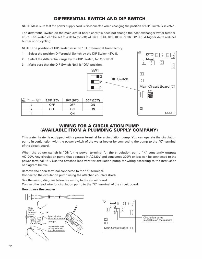
DIFFERENTIAL SWITCH AND DIP SWITCH
NOTE: Make sure that the power supply cord is disconnected when changing the position of DIP Switch is selected.
The differential switch on the main circuit board controls does not change the heat exchanger water temper-ature. The switch can be set at a delta (on/off) of 3.6˚F (2˚C), 18˚F(10˚C), or 36˚F (20˚C). A higher delta reducesburner short cycling.
NOTE: The position of DIP Switch is set to 18˚F differential from factory.
1. Select the position Differential Switch by the DIP Switch (SW1).
2. Select the differential range by the DIP Switch, No.2 or No.3.
3. Make sure that the DIP Switch No.1 is "ON" position.
WIRING FOR A CIRCULATION PUMP(AVAILABLE FROM A PLUMBING SUPPLY COMPANY)
This water heater is equipped with a power terminal for a circulation pump. You can operate the circulationpump in conjunction with the power switch of the water heater by connecting the pump to the “K” terminalof the circuit board.
When the power switch is “ON”, the power terminal for the circulation pump “K” constantly outputsAC120V. Any circulation pump that operates in AC120V and consumes 300W or less can be connected to thepower terminal “K”. Use the attached lead wire for circulation pump for wiring according to the instructionof diagram below.
Remove the open-terminal connected to the “K” terminal.Connect to the circulation pump using the attached couplers (Red).
See the wiring diagram below for wiring to the circuit board.Connect the lead wire for circulation pump to the “K” terminal of the circuit board.
11
Circulation pump(available on the market)
Main Circuit Board
(K)
Make3/16 in.(4-5mm)space.
Lead wire forcirculation pump
Stopper
Power lead wireof the externalcirculation pump
How to use the coupler
3
2
1
No. DIFF 3.6˚F (2˚C)
OFF
OFF
18˚F (10˚C)
OFF
ON
ON
36˚F (20˚C)
ON
ON
3
SW1
DIP Switch2
1 Main Circuit BoardSW1
K
OM-128HH_In_US.qxd 14.3.7 13:22 ページ 11
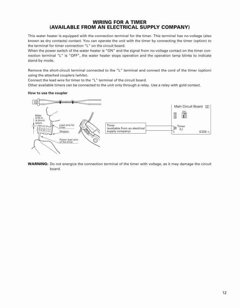
WIRING FOR A TIMER(AVAILABLE FROM AN ELECTRICAL SUPPLY COMPANY)
This water heater is equipped with the connection terminal for the timer. This terminal has no-voltage (alsoknown as dry contacts) contact. You can operate the unit with the timer by connecting the timer (option) tothe terminal for timer connection “L” on the circuit board.When the power switch of the water heater is “ON” and the signal from no-voltage contact on the timer con-nection terminal “L” is “OFF”, the water heater stops operation and the operation lamp blinks to indicatestand-by mode.
Remove the short-circuit terminal connected to the “L” terminal and connect the cord of the timer (option)using the attached couplers (white).Connect the lead wire for timer to the “L” terminal of the circuit board.Other available timers can be connected to the unit only through a relay. Use a relay with gold contact.
WARNING: Do not energize the connection terminal of the timer with voltage, as it may damage the circuitboard.
12
Timer(L)
Main Circuit Board
3
SW1
2
1
Timer(available from an electricalsupply company)
Make3/16 in.(4-5mm)space.
Lead wire fortimer
Stopper
Power lead wireof the timer
How to use the coupler
OM-128HH_In_US.qxd 14.3.7 13:22 ページ 12

13
INSTALLATION OF THE UNIT AND FLUE PIPESAFETY TIPS
WARNING:
1. The flue pipe opening must be fully exposed to outside air. Do not vent into a garage, basement, underthe floor, or into any enclosed area.
2. Do not install the flue pipe in close proximity to other objects or materials.3. Before making a hole in your wall for the flue pipe, make sure the area is free of electrical wires, gas
pipes and other obstacles.4. Do not install the flue pipe where it will be exposed to heavy snow, collected leaves, or strong winds.
IMPORTANT: In areas of heavy snow fall, ground surface clearance must be increased according toaverage snow falls.In open areas with strong wind, a wind breaker may be necessary.
5. Do not install the flue pipe below the water heater.6. The exhaust pipe should be properly installed and connected. Aluminum tape may be used for sealing
exhaust pipe connections.7. Always cover the exhaust pipe with the insulating cloth cover.8. If installed in building without an eave, a non-combustion eave should be installed directly above the
flue pipe.
CAUTION:Total length of the extension pipe between the water heater and the flue pipe mustbe no greater than 10 ft. with a total of three bends.
NOTE: When using extension pipes always cover the exhaust pipe with the insu-lating cloth cover.
INSTALLATION OF UNIT
1. Install the unit on a noncombustible surface in a stable position. If installing on a combustible floor, theunit should be raised up off the floor to prevent contact with combustible materials by using brick, con-crete block or similar non-combustible material.If minimum clearances between the unit and combustible construction are maintained, no ventilationopenings are needed in the closet door when installed in a closet.
¡ UNIT (INDOOR CLEARANCE)Left side 6 in. (150 mm)Right side 6 in. (150 mm)Rear side 6 in. (150 mm)Front 2 ft. (600 mm)From front door to closet 6 in. (150 mm)Top 2 ft. (600 mm)
¡ If the combustible material is protected withnon-combustible material such as 0.024 (24-gage) sheet metal with ventilated air space, thefollowing clearance is applied.
Left side 2 in. (50 mm)Right side 2 in. (50 mm)Rear side 2 in. (50 mm)
NOTE: It is important to keep enough clearance for the purpose of maintenance, repair and possible servicing.We recommend the following clearance for servicing.
Left side 2 ft. (600 mm)Front 5 ft. (1.5 m)
¡ FLUE PIPE (OUTSIDE CLEARANCE)From flue pipe top to combustible surface: Vertical 24 in. (600 mm)From flue pipe top to combustible surface: Horizontal 24 in. (600 mm)
¡ EXTENSION EXHAUST PIPE (WITH INSULATING CLOTH)From extension exhaust pipe to combustible surface: Vertical 3 in. (76 mm)From extension exhaust pipe to combustible surface: Horizontal 3 in. (76 mm)
2. Check local codes regarding installation of the water heater, water piping and fuel tank.
Combustible object
Flue pipe topmore than 2ft.(600mm)
more than 2ft.(600mm)
more than 6 in.(150mm)
more than 2ft.(600mm)
more than 2ft.(600mm)
morethan 2ft.(600mm)
morethan 2ft.(600mm)
Intakeair
Intakeair
Combustible object
Combustible object
Exhaust gas
Exhaust gas
Combustible object
OM-128HH_In_US.qxd 14.3.7 13:22 ページ 13

14
INSTALLATION OF FLUE PIPE
IMPORTANT: Check and comply with all state and local codes that may apply to water heater before begin-ning installation.
1. Select unit location. Allow clearances as indicated above between the unit and all other materials2. Make sure that the outside area to where the flue pipe will reach is clear of any objects.
NOTE: Make sure wall thickness is not greater than 10-1/2 inches. For walls between 10" and 18" useFlue Pipe Extension Part #20476486. Flue pipe can be installed through any standard buildingmaterials.
3. For standard installation, position the hole for the flue pipe. (See diagram on page 16)NOTE: The water heater should be installed on a sturdy floor that is level and flat.
4. Cut the hole for the flue pipe from inside the room. Use a 4-3/4" diameter hole saw attached to an elec-tric drill. The opening on the inside wall should be slightly higher than the outside opening (approxi-mately 1/4") so that the flue pipe will slope slightly downward (approximately 3 degrees) after it isinstalled. This will enable condensed moisture to drain from the flue pipe to the outside and preventrain or snow from entering from outside after installation.
5. Install the inner flange and the flange gasket to the inner flue pipe and insert the inner flue pipe throughthe wall hole from inside the room. Make sure the arrow on the inner flange is pointing up and securethe securing band with a screw and a nut through two holes of the fixing band. Secure the inner fluepipe to the wall with the four screws provided with the unit.
6. Install the flange gasket to the outer flue pipe. Secure the outer flue pipe to the wall by turning it clock-wise. Continue turning the outer flue pipe until the inner and outer flanges fit tightly against the innerand outer walls.
7. Insert the flexible exhaust pipe to the flexible bent joint until it locks. Insert the flexible bent joint to theexhaust opening of the inner flue pipe until it locks.NOTE: The flexible exhaust pipe and flexible bent joint have claws to prevent them from being sepa-
rated. When connecting them, raise the claws a little.These claws may be raised already depending on production lots. If this is the case, insert themas they are. Do not attempt to draw a pipe off in any event while the claw is raised. Otherwise,it could cause a leak of exhaust gas.
Indoor
Hole saw
3° 3°
Inner flange
Self tapping screw Nut
Inner flue pipe
Flange gasket
screw
Outer flue pipe
Flange gasket
Inner flue pipe
Tab
Flexiblebent joint
Flexibleexhaust pipe
Tab
Inner fluepipe
Flexible bent joint
Raise the claw a littlewith pliers or the like.
Approx.3 mm
OM-128HH_In_US.qxd 14.3.7 13:22 ページ 14

15
8. Slide the insulating cloth cover over the flexible exhaust pipe and the flexible bent joint.
NOTE: When disconnecting the extension pipe (such as flexible pipe and flexible bent joint), turn clockwise and pull apart.
9. Remove the screw from the exhaust opening of the unit. Insert the flexible exhaust pipe to the exhaustopening and secure them with the screw.NOTE: Seal all connections of the pipes with the aluminum tape.
CAUTION: ¡Do not attempt to insert the exhaust pipe forcibly.¡If O-ring is damaged, it could cause a leak of exhaust gas.¡If the exhaust pipe is inserted after raising the claw, the pipe is locked in position with the
claw so that the pipe will become unable to remove.¡If it is attempted to remove forcibly, the exhaust pipe may be broken.
10. Connect rubber joints to the both ends of the inlet hose.
11. Place the hose bands on the rubber joints and attach the hose as shown below. Tighten the bands.
Insulatingcloth cover
Rubber jointRubber jointInlet hose
Hose band
Hose band
OM-128HH_In_US.qxd 14.3.7 13:22 ページ 15

16
PREPARATION
1. Make sure the flue pipe is installed properly.2. Make sure the fuel tank is installed properly. Make sure there is no fuel leakage.3. Make sure there is no water leaking from piping. (Plumbing)4. Make sure electrical connections and grounding are wired properly.5. Make sure the floor is stable and can withstand strong vibration and the weight of a full water heater.6. Make sure the area is free of flammable materials.7. Check for air trapped in fuel lines.
OPERATION
1. Open the fuel supply valve.2. Press "POWER SWITCH" to "ON". "OPERATION" lamp will come on. Automatic operation is based upon
the temperature of water inside the heat exchanger. "BURNER" lamp is lit when the burner is in its oper-ation mode.NOTE: When operating for the first time or after running out of fuel, ignition may not occur because of
air in the fuel line. In that case, remove air as described in the previous section.
SECTION D:TEST RUN
10-1/2 in. (270 mm)maximum
Rubber joint
Flange gasket
Outer flue pipe
Tight band
Inner sleeve flange
Inlet hose
Aluminum tape
Flexible exhaust pipe
Exhaust pipe ring
Inner flue pipe
4~10-1/2 in.(100~270 mm)Insulating cloth cover
Flexible bent joint
Rubber joint
Hose band
14-1
/2~
17 in
. (37
0~43
0 m
m)
Hose band
OM-128HH_In_US.qxd 14.3.7 13:22 ページ 16
17
SECTION E: CHIMNEY INSTALLATION
This unit is a sealed combustion system and as an installation option it may be connected directly to a chimney. Using this option, room air is used for combustion and the exhaust gases are vented into the chimney to the outside.
IMPORTANT:
1. This appliance should be installed by a licensed, authorized person(s) due to necessity ofmaking electrical, water and fuel connections. Check local codes and ordinances and/or the latestedition of the National Fire Protection Association Standard for the Installation of Oil-BurningEquipment. NFPA-31.
2. A Barometric Draft Regulator must be used in the exhaust pipe to stabilize flue draft. It is requiredthat a UL-listed (Underwriters Laboratories) damper be used. The Barometric Draft Regulator mustbe installed in accordance with NFPA-31.
3. Installation in an unconfined space in buildings of conventional frame, brick or stone construction,infiltration normally is adequate to provide air for combustion and ventilation. For confined spaces, openings for air intake and venting must be provided. (See Fig.1.) Or connect AirIntake Inlet port directly to outside air with 3 or 4 inch aluminum pipe.Check local codes and ordinances and/or NFPA-31 Code for specific details.
4. It is recommended that the OM-180 hot water heater be connected to an independent chimney flue.
5. Select a place that can draw in sufficient air for combustion. The air intake hole should be placed in aspot that can draw in outside air near the floor.
CAUTION:
1. In case another appliance is connected to the same chimney flue (2 or more units), it may be necessaryto comply with state and local codes.
2. Connecting the OM-180 hot water heater with two or more appliances using the same chimney flue mayaffect the performance of the hot water heater.
3. Total length of the exhaust pipe and the chimney liner must be no greater than 25 ft. Maintain the shortestpiping possible by selecting a location as close as posssible to the chimney.
NOTE:1. To prevent against exhaust leaks, make sure all connections are properly fitted and seal connection with
aluminum tape or heat resistant sealing material.
2. Chimney liner should be the same size as the exhaust pipe. Exposed exhaust pipe should be protectedwith appropriate insulation.
3. For a chimney installation, use accessory (option) parts. Chimney Installation Adapter kit(Part #20476430-Dia.5“ or Part #20476415-Dia.4”)
Required opening area (confined space) = 155 in2 × 2 places
OM-128HH_In_US.qxd 14.3.7 13:22 ページ 17
18
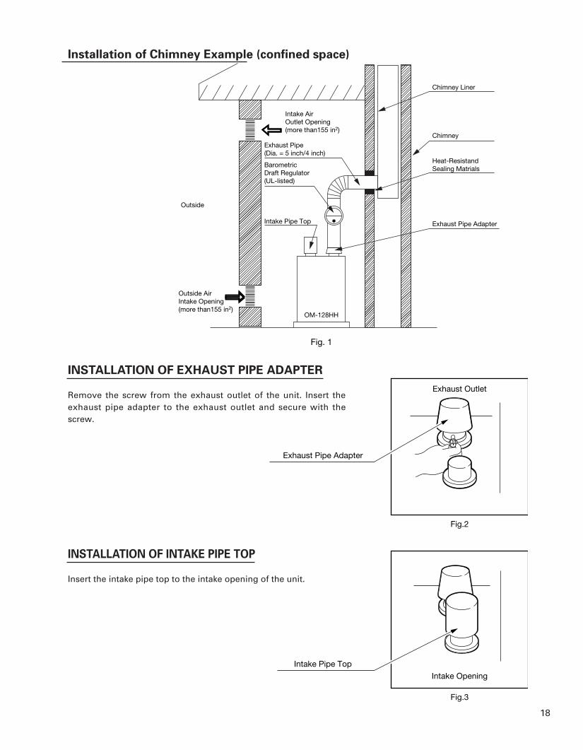
Installation of Chimney Example (confined space)
INSTALLATION OF EXHAUST PIPE ADAPTER
Remove the screw from the exhaust outlet of the unit. Insert theexhaust pipe adapter to the exhaust outlet and secure with thescrew.
INSTALLATION OF INTAKE PIPE TOP
Insert the intake pipe top to the intake opening of the unit.
Intake Opening
Exhaust Outlet
Exhaust Pipe Adapter
Fig.2
Fig.3
Intake Pipe Top
Exhaust Pipe(Dia. = 5 inch/4 inch)
BarometricDraft Regulator(UL-listed)
Exhaust Pipe Adapter
Fig. 1
OM-128HH
Intake Pipe Top
Intake AirOutlet Opening(more than155 in2)
Outside
Outside AirIntake Opening(more than155 in2)
Chimney Liner
Chimney
Heat-ResistandSealing Matrials
OM-128HH_In_US.qxd 14.3.7 13:22 ページ 18

New 03/14Printed in Japan
7638003052
TOYOTOMI U.S.A., INC.604 Federal Road, Brookfield, CT 06804
www.toyotomiusa.com
This manual supersedes earlier editions. PART No.20476994
OM-128HH_In_US.qxd 14.3.7 13:22 ページ a