instantaneous electric shower installation instructions · any parts. screw mounting ......
TRANSCRIPT

Instantaneous Electric ShowerInstallation Instructions
IMPORTANT!This Step-by-Step guide should be given to the customer
after installation and demonstration.

CONTENTS & FEATURES
QIQUICK INSTALLATIONa guide for installers
The MX range of QI showers have been especially design for Quick Installation. Both water and electrics can enter the shower unit from 8 different positions. The unit is wired for both left and right orientation. Removable corner units allow for easy plumbing and the filter can be removed quickly and easily without the removal of any parts. Screw mounting hole positions are visible when the cover is off for accurate installation.
Temperature
• 1.ShowerUnit
• 2.Showerhead
• 6.FlexibleShowerHose
• 4.RiserRailBracket
• 4.RiserRailBracket
• 3.RiserRailTube
• 5.RiserRail HeightAdjuster
• 7.SoapDish
• 8.HoseRetaining Ring
• 9.ScrewPacks
• 10.FittingInstructions& Guarantee Card
Instantaneous Electric ShowerInstallation Instructions
IMPORTANT!This Step-by-Step guide should be given to the customer
after installation and demonstration.
PACK CONTENTSPlease make sure all components are included before starting installation.
1. ShowerUnit2. Showerhead3. RiserRailTube4. RiserRailBracketsx25. RiserRailHeightAdjuster6. FlexibleShowerHose7. SoapDish8. HoseRetainingRing9. ScrewPacks10.FittingInstructions& Guarantee Card

1. PLEASE READ THIS IMPORTANT SAFETY INFORMATION
Products manufactured by the MX Group are safe and without risk provided they are installed, used and maintained in good working order in accordance with our instructions and recommendations.
WARNING: DO NOT operate shower if frozen, or suspected of being frozen. It must thaw out before using.
DO NOT operate the unit if the showerhead or spray hose becomes damaged.
DO NOT restrict flow out of shower by placing showerhead in direct contact with your body.
DO NOT operate the shower if water ceases to flow during use or if water has entered inside the unit because of an incorrectly fitted cover.
WARNING: If restarting the shower immediately after stopping, be aware that a slug of hot water will be expelled for the first few seconds.
These instructions contain all the necessary fitting and operating instructions for your electric shower. Care taken during the installation will provide a long, trouble free life from your shower.
!
!
!
!
!
!
!
!
!
!

1. PLEASE READ THIS IMPORTANT SAFETY INFORMATION (CONT.)
IMPORTANT: This appliance is not intended for use by persons (Including children) with reduced physical, sensory or mental capabilities, or lack of experience and knowledge, unless they have been given supervision or instruction concerning use of the appliance by a person responsible for their safety. Children should be supervised to ensure that they do not play with the appliance.
DEFAULT PLUMBING SETTING: The shower unit is supplied for right hand installation. To plumb the unit on the left you must remove the blanking cap and refit it to the inlet pipe on the right hand side of the unit ensuring the metal fixing clip is pushed firmly into the groove. When leak testing the installation you must ensure there are no leaks from this area.
IMPORTANT: To comply with water regulations, building regulations or any specific local water company regulations and should be in accordance with BS EN 806. A double check valve must be fitted with all flexible shower accessories where it is possible that the showerhead may come into contact with used water i.e. In the bath or shower tray.
IMPORTANT: Before turning on the water supply to the shower unit the water supply pipe should be flushed out to remove debris. After flushing the pipework ensure that the shower unit is positioned squarely on the wall and tighten the screws. Tighten all plumbing connections and check the pipework for leaks.
IMPORTANT: Ensure that the terminal block screws are fully tightened and that no cable insulation is trapped under screws. Ensure the cable clamp is used to secure the cable. The earth continuity conductor of the electrical installation must be effectively bonded to earth on the fuse board.
CAUTION: Check there are no hidden cables or pipes before drilling holes for wall plugs. Exercise great care when using power tools near water. The use of a residual current device (RCD) is recommended.

IMPORTANT: Turn the Temperature control knob anticlockwise until the valve is fully open before switching on the unit. This will ensure a fast fill up of the unit when the shower is first switched on.
IMPORTANT: The shower unit must be full of water before heat settings are used.
WARNING: If re-starting the shower immediately after stopping, be aware that a slug of hot water will be expelled for the first few seconds.
ATTENTION: Do not operate the shower unit if the showerhead or hose becomes damaged. The shower is designed and approved to EN-60335 with the showerhead provided. Under no circumstances must any showerhead that is not approved by the manufacturer be used with this product.
IMPORTANT: The shower spray head and shower filter MUST be cleaned regularly to remove scale and debris. The frequency of cleaning will vary according to local water quality. If the water becomes hot and you are unable to obtain cooler water, immediately check the showerhead and filter for blockage. See section 12 for comprehensive cleaning advice.
WARNINGDO NOT FIT ANY ECO FLOW CONTROL SYSTEMS OR FLOW CONTROL/REDUCING
WASHERS IN THE SHOWER HOSE/SHOWERHEAD OR ANY OTHER PART OF THE SHOWER UNIT.
ONLY USE THE BLUE SEALING WASHER SUPPLIED WITH THE SHOWER HOSE.
!
!
!
!
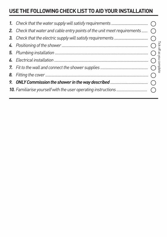
USE THE FOLLOWING CHECK LIST TO AID YOUR INSTALLATION
1. Check that the water supply will satisfy requirements .....................................
2. Check that water and cable entry points of the unit meet requirements ......
3. Check that the electric supply will satisfy requirements ..................................
4. Positioning of the shower .......................................................................................
5. Plumbing installation ..............................................................................................
6. Electrical installation ...............................................................................................
7. Fit to the wall and connect the shower supplies ................................................
8. Fitting the cover ........................................................................................................
9. ONLY Commission the shower in the way described ......................................
10. Familiarise yourself with the user operating instructions ...............................
Tick off as you complete

2. IMPORTANTn Shower Installation must be carried out by a suitably qualified person and conform with IEE Regulations and comply with water regulations, building regulations or any specific local water company regulations and should be in accordance withBSEN806.
n This shower unit is designed to be connected to a 15mmcoldwatermainssupply.Do not connect to a tank supply unless a suitable booster pump is fitted.
n To make sure of activating the heating elements, the shower must be connected to a mains water supplywithaminimumrunningpressureof100kPa(15lb/sqin)-(1Bar)ataminimumflowrateof 8litresperminute.Themaximumstaticpressuremustbenogreaterthan1000kPa(150lb/sqin)- (10Bar).(Minimumrunningpressuremustbeobtainedat9litres/minutefor9.5kWand11litres/minuteforthe10.5kW).
n The shower unit must not be fitted where it may beexposedtofrost,forexampleinanoutdoorarea.The shower must not be used if suspected of being frozen.Frostdamageisnotcoveredbytheguarantee.
n Plumbers jointing compound must not be used. IninstancesofdifficultjointsuseP.T.F.E.Tape. The use of compound invalidates the guarantee.
nAllplumbingconnectionsmustbecompletedbefore making the electrical connections.
n The outlet of your shower acts as a vent and must NOT be connected to any form of tap or fitting not recommended by the MX Group.
nAlwaysswitchoffattheisolatingswitchwhennotin use.
3. GENERAL ADVICE TO SHOWER UNIT USERS The following points will help you to understand how your MX shower unit operates.
Theflowrateofwaterpassingthroughtheshowerunit determines the water temperature. The lower the flowthewarmerthewater,thehighertheflowthecooler the water.
The temperature produced by the shower unit will vary between seasons on any one setting of the temperature control. This is due to variance in the temperature of the water supply, which becomes cooler in winter than summer.
The stabiliser valve maintains an almost constant shower temperature during mains water pressure changes.
Ifchangesintemperatureareexperiencedinnormaluse, it is likely to be caused by water pressure falling belowtheminimumlevel.Fallsinwaterpressuremaybe due to water being drawn off at other points within the building.
The showerhead and filter must be cleaned regularly to remove scale and debris. If the water becomes hot and you are unable to obtain cooler water, check the showerhead and filter for blockage.

4. GENERAL LAYOUT OF A SHOWER INSTALLATION ATYPICALINSTANTANEOUSELECTRICSHOWERINSTALLATION
Planyourowninstallationcarefully.Checkonthenearest and most readily accessible rising mains water supply, this may be beneath the bath or in the loft,whereitfeedsthecoldwaterstoragetank.Useonly the cold rising water main supply.
Do not connect the shower unit to the outlet from the cold water tank.
Avoidconnectingtheshowerunit,ifpossible,were it will be affected by water drawn off by other appliances,e.g.FromthemainsfeedtotheW.C. This may cause a drop in pressure too low for the shower unit to work correctly.
Anisolatingvalvemustbefittedtocomplywithwaterregulations and for servicing purposes.
BATH
COLD WATER MAINS SUPPLY
SEPARATE PERMANENTLY CONNECTED SUPPLY
FROM CONSUMER UNIT
ISOLATING STOP TAP
DOUBLE POLEHEATER SWITCHWALL MOUNTEDIN ACCORDANCEWITH LOCALAUTHORITYREGULATIONS
SHOWERUNIT
BATHROOM
FLOOR
CEILING JOISTS
IMPORTANTThisapplianceisnotintendedforusebypersons(Includingchildren)withreducedphysical,sensoryormentalcapabilities,orlackofexperienceandknowledge,unlesstheyhavebeengivensupervisionor
instruction concerning use of the appliance by a person responsible for their safety. Children should be supervised to ensure that they do not play with the appliance.
!
!
!
!

5. INSTALLATION Positionyourshowerunitonthewallawayfromthedirect spray of the shower and at about the same height as the showerhead position.
The shower unit should be positioned so that the showerhead cannot be immersed in the bath or shower tray when hanging down.
Placetheshowerunitonthewallandmarkthelocationofthefixingscrewsthroughthebackplate.
Carefully drill the holes as marked using a sharp 5.5mmmasonrydrillafterfirsthavingmadecertainthere are no pipes or wires behind the proposed holes.
Fixtheshowerunittothewallusingtheplugsandscrews provided, do not fully tighten at this stage.
Temperature
PRODUCT POSITIONING GUIDE
Shower unit can be mounted either side of riser rail
Heightofshowerhead and shower to suit user’s requirements
Mains cold water supply (either top, bottom, left, right or rear entry
25mmminimum
Outline of bath or shower tray
Spillover level
Spillover level
Soap dish
Hoseretainingring

6. PLUMBING CONNECTIONS
The 8 arrows depict water and electrical entry points
Locationholesformounting are easily marked off from inside unit
Bottomfixingposition
Lefthandwater entry sealing cap and clip
NOTE!PLUMBING THE SHOWER UNIT MUST PROCEED WIRING!
QIQUICK INSTALLATIONAsyoucanseefromthediagram right the shower unit can be both plumbed and wired from 8 different positions;n Top right n Top left n Bottom right n Bottom left n Right side nLeftside n Rear right n Rear left
Removable cover plates for left or right and bottom inlets, accessible once cover plate is removed. These simply slide into place before replacement of cover.
Waterinlet,thiscanbeswitchedwiththecapandfixingclipopposite to change water input direction.
Seenextpageforinstruction.

IMPORTANTBeforeturningonthewatersupplytotheshowerunitthewatersupplypipeshouldbeflushedouttoremovedebris.Afterflushingthepipeworkensurethattheshowerunitispositionedsquarelyonthewallandtighten
the screws. Tighten all plumbing connections and check the pipework for leaks.
IMPORTANTTo comply with water regulations, building regulations or any specific local water company regulations and
shouldbeinaccordancewithBSEN806.Adoublecheckvalvemustbefittedwithallflexible shower accessories where it is possible that the showerhead may come into contact with used water
i.e. In the bath or shower tray.
!
!
!
!
!
!
!
!
PLUMBING CONNECTIONS Water inlet direction option
The shower unit is supplied for right hand installation. To plumb the unit on the left you must:
1.Pullthemetalretainingclipoutoftheblankingendcap with a pair of pliers.
2.Removetheblankingcap-pulloff.
3.Simplyrefitblankingcaptotheinletpipeontheright hand side of the unit.
4.Re-insertthemetalfixingclipensuringitispushedfirmly into the groove.
5.Whenleaktestingtheinstallationyoumustensurethere are no leaks from this area.
Turn off the water supply at the isolating stop tap. Havingdeterminedthedirectionoftheinletwatersupply:Top(falling),Bottom(rising),orBackinlets.Itis necessary to remove the appropriate plastic cross section from the back plate, before commencing with the installation.
Wehaveincorporatedintothebottomright&left-hand side of the back plate easy removable trim sections to allow easy access when connecting the water supply.
(PleaseNote!Remembertoreplacethistrimsectionbeforerefittingthecover).
Connect the mains water supply to the inlet of the showerunitusinga15mmcopper,stainlessorplasticpipewitha15mmcompressionelbowor15mm push-fitelbow.
Donotuseexcessiveforcewhenmakingtheconnection to the unit.
DEFAULTPLUMBINGSETTINGThe shower unit is supplied for right hand
installation. To plumb the unit on the left you must remove the blanking cap and refit it to the inlet pipe on the right hand side of the unit ensuring the metal fixingclipispushedfirmlyintothegroove.When
leak testing the installation you must ensure there are no leaks from this area.

7. ELECTRICAL CONNECTIONS
ELECTRICAL SPECIFICATIONS
The shower unit must be permanently connected to the electricity supply, direct from the consumer unit via a double pole linked switch with a minimum contactgapof3mm.Theswitchmustbereadilyaccessible and clearly identifiable and out of reach ofapersonusingafixedbathorshowertray,unlessthe switch is cord operated. The wiring must be connected to the switch without the use of a plug or socket outlet.
ThecablesizerequiredisdeterminedbythekWrating of the shower and the distance between the shower and the consumer unit. The table below will help you choose the correct cable for your installation, but it will depend upon the precise circumstances of the installation. If you are in any doubt consult an electrician.
The incoming cable should be hidden.
NOTE:theshowercontains2separatesetsofconnecting terminal blocks so the shower can be wired for left or right installation with minimum effort. Only connect to one of the terminal blocks.
The diagram below shows the route of the cable into the shower unit for connection to the terminal blocks, connect as follows:
Earth cable to terminal marked
Neutral cable to terminal marked N
Live cable to terminal marked L
IMPORTANTEnsure that the terminal block screws are fully tightened and that no cable insulation is trapped under
screws. Ensure the cable clamp is used to secure the cable. The earth continuity conductor of the electrical installationmustbeeffectivelyconnectedtoallexposedmetalpartsofotherappliancesandservicesinthe
room in which the shower unit is installed to confirm
!
!
!
!
KWRATING
NOMINALAT240V
MINRATINGOFISOLATINGSWITCH
FUSERATING
MAXCABLE RUN
6mm 10mm
7.0 29.10amps 30amps 30amps 29m 48m
7.5 31.25amps 40amps 40amps 27m 44m
8.0 33.33amps 40amps 40amps 25m 42m
8.5 35.41amps 40amps 40amps 23m 38m
9.5 39.58amps 40amps 40amps 21m 32m
10.5 43.75amps 45amps 45amps 18m 30m
NominalPowerratingat240V
7.5kW-(32AMCBrating)8.5kW-(40AMCBrating)9.5kW-(40AMCBrating)10.5kW-(45AMCBrating)
NominalPowerratingat230V
6.9kW-(32AMCBrating)7.8kW-(40AMCBrating)8.7kW-(40AMCBrating)9.6kW-(45AMCBrating)
LN
E
Terminalblock
1. Terminal block2. Power neon3. Right microswitch4. Left microswitch
4
5
7
6
L
N
E
inletoutlet
1
3
6
7
2
5. Thermal cut-out6. Elements7. Earth

STOPSTOP
The diagram right shows a schematic wiring diagram.
IMPORTANT:Whenconnectingthecablefully tighten the terminal block screws and make sure that no cable insulation is trapped under the screws.Looseconnectionscanresultincable overheating.
NOTE: The supply cable earth conductor must be sleeved. The outer sheath of the supply cable must be stripped back to the minimum.
The use of connections within the unit or other points in the shower circuit to supply powertootherequipmenti.e.extractorfans, pumps etc. will invalidate the guarantee.
DO NOT switch on the electricity supply until the shower cover has been fitted.
NOTE: TheelementsonUKmodelsareto 240VspecificationandwillgivealowerkW ratingifthevoltagesupplyisbelow240V.
8. FITTING THE COVER BACK INTO POSITION NOTE:ItisnecessarytoalignthePowerSelectorandTemperature knobs in the cover with their opposite control spindles before the cover is fitted.
FirstturnthePowerselectorknobtotheON/OFF position then turn the Temperature knob anti-clockwisetothestop.
ThenintheinternalunitmakesurethePowerselector keyway is pointing to the left and the Temperature spline spindle is rotated fully anti-clockwiseuntilitreachesthestop.
The cover can now be fitted and secured withthefourfixingscrewsprovided.
Re-fittheshowerheadtotheflexiblehose. Yourshowerisnowreadytocommission.
LN
E
Terminalblock
1. Terminal block2. 3.
Right microswitch4.
Left microswitch
3
4
6
5
L
N
E
inletoutlet
1
2
5
6
Fig.11
5. Thermal cut-out
6. Elements Earth

9. RISER RAIL FITTING INSTRUCTIONS 1. Establish position for the riser rail, and mark
the wall for the lower mounting bracket. Make allowances for the tallest person likely to use the shower regularly.
2. Remove covers from the wall brackets.
3.Positionthelowerbracketandmarkthewallforthescrewfixing.Thendrillandplugthewallandfixthe lower bracket without the rail location notch.
4.Fittherailintothelowerbracket.Placetheremaining bracket with the rail location notch on top of the rail, making sure that the rail slot is located into the notch. Ensure the hole position is vertically aligned and mark the wall. Remove the rail and bracket, then drill and plug the wall.
5.Slidetheheightadjusterontotherail.Tightentothe rail by turning the locking cap. Then fit the soap dish, dampening the rail will make it easier to slideon.Finallyfitthehoseretainingringontothebottom of the rail below the soap dish.
6. Replace the rail assembly into the lower bracket. Refit the top bracket, ensuring the slot in the rail is locatedintothebracketnotchandfixtothewall.
7. Slide covers onto both brackets.
8.Firmlyattachflexiblehosetoshowerheadmakingsure sealing washer is in place after first passing through the hose retaining ring.
NOTE:Theadjustableheightadjustergripstheconicalends of the hose, not the handle of the showerhead.
CAUTIONCheck there are no hidden cables or pipes before drilling holes for wall plugs.
Exercisegreatcarewhenusingpowertoolsnearwater. Theuseofaresidualcurrentdevice(RCD)isrecommended.
!
!
!
!
Duo QI
eco
eco
Temperature TIPS
ApieceofinsulatingormaskingtapeappliedtothewallbeforemarkingouttheFixingholeswill
help stop the drill from wandering, particularly on tiledsurfaces.Whenworkingnearabasinorbath,
insert the plug in the waste fitting so that small parts cannot be lost.
Take care not to drop accessories or tools into basin or bath.
!
!

10. COMMISSIONING THE SHOWER
1. Make sure that the electrical supply has been isolated at the double pole isolating switch.
2. Turn the top power selector knob to the ‘Cold’ setting(SolidBlueSymbol).
3. Turn the bottom temperature control knob anti-clockwisetothefullcoldposition.
4. Ensuring the water supply is fully on at the mains stopcockandisolatingservicevalve(iffitted),check that water is not leaking from the bottom of the case.
5. Switch on the electrical supply at the double pole switch.
6. Turn the power selector knob to the cold position.Checkthatwaterflowsfreelyfromtheshower within a few seconds. The water from the showerhead will be at full force and at a cool temperature.
7. Rotate the bottom temperature control knob slowly clockwise fully. This will gradually reducetheflowwiththewatertemperatureremaining cool.
8.Returntheknobanti-clockwisetomaximumflow.
9. Now turn the top power selector knob to the ‘Low’setting(OutlineRedECOSymbol). Allowafewsecondsforthewarmertemperaturetoreachtheshowerhead-thisshowsthatthe‘ECO’ power setting is operating correctly.
10. Now turn the top power selector knob to the‘High’setting(SolidRedSymbol).Thetemperatureshouldrisefurther-thisshowsthat the full power setting is operating correctly.
11. Turn the bottom temperature control knob clockwiseforhotterwaterandanti-clockwiseforcoolerwater.Allowafewsecondsbetweenselections-forthetemperaturechangeto reach the showerhead.
NOTE. When the temperature is changed the flow rate alters.
12. Turn the power selector knob to the OFF position.
13.Switchoffpull-cordorwallmountedswitch.
14. Remove the shower head and make sure no debris has worked into it. Clean and refit.
15. Remove the filter and clean out any debris from the pipework, clean and refit.
IMPORTANTThe shower unit must be full of water before heat settings are used.
IMPORTANTTurn the Temperature control knob anticlockwise until the valve is fully open before switching on the unit.
This will ensure a fast fill up of the unit when the shower is first switched on.
!
!
!
!
!
!
!
!

11. OPERATING THE SHOWER
1. Switchonpull-cordorwallmountedswitch.
2. Turn the power selector knob to the cold setting •forimmediatewaterflow.
3. Select your power setting using the top control. The shower has three positions COLD •, ECO m and FULL• power.
COLD •setting(SolidBlueSymbol):Adjustmentoftheflowcontrolonthissettingwillonlyaltertheflowofwaternotthewatertemperature.
ECO m settings(OpenRedSymbol):
This is the low power setting for economy during warmer months or when a cool showerisrequired.Temperatureadjustmentis via the bottom temperature control.
FULL • setting(SolidRedSymbol):
This is the full power setting. Temperature adjustmentisviathebottomtemperaturecontrol.
4.Waitafewsecondsforthewarmerwatertoreach the showerhead.
5. If necessary turn bottom ‘Temperature’ control knob slowly to obtain desired showeringtemperature.Again,waitingafewsecondsaftereachadjustmentintemperature to reach the showerhead.
Note: To adjust the shower temperature. The water temperature is altered by increasing ordecreasingtheflowrateofwaterthroughtheshower unit via the temperature control.
To increase the shower temperature. Turn the temperature control knob clockwise, thiswilldecreasetheflowofwaterandincreasethe shower temperature.
To decrease the shower temperature. Turn the temperaturecontrolknobanti-clockwise,thiswillincreasetheflowofwateranddecreasetheshower temperature.
6. To turn off the shower unit, turn the power selector knob to the OFF position.
7.Asmallamountofwaterwillberetainedinthe showerhead after the shower has been turned off. This may drain over a few minutes.
8. Switchofpull-cordorwallmountedswitch.
WARNINGIF RE-STARTING THE SHOWER IMMEDIATELY AFTER STOPPING, BE AWARE THAT A SLUG
OF HOT WATER WILL BE EXPELLED FOR THE FIRST FEW SECONDS.
!
!
!
!
Duo QI
eco
eco
Temperature
COOLER WARMEReco eco
ecoeco
eco eco
ecoecoON/OFF
COLD
HOT
ECO

12. SHOWERHEAD CLEANING INSTRUCTIONS
The showerhead should be cleaned periodically to remove limescale or debris which will reduce the performance of the shower. The frequency of cleaning will vary according to local water quality.
PERIODICAL MAINTENANCE
1. To break away scale deposits on a daily basis simply rub your thumb over the surface whilst the shower is running.
2. If scale deposits are stubborn,soak the showerhead in a proprietary limescale remover and rinse thoroughly before use.
3. Remove the filter from the bottom of the shower clean out any debris by washing in clean water. Refit filter.
ATTENTION!DO NOT OPERATE THE SHOWER UNIT IF THE SHOWERHEAD
OR HOSE BECOMES DAMAGED.
THE SHOWER IS DESIGNED AND APPROVED TO EN-60335 WITH THE SHOWERHEAD PROVIDED. UNDER NO CIRCUMSTANCES MUST ANY SHOWERHEAD THAT IS NOT
APPROVED BY THE MANUFACTURER BE USED WITH THIS PRODUCT.

13. FAQ’S - FREQUENTLY ASKED QUESTIONS Q. Water does not flow when turned on.
A. Sixthingstocheck.
1.Checkthemainscircuitbreakerand/orfuse.
2.Checktheisolationswitchinthebathroom.
3.Checkthepowerfromtheisolationswitchtothe unit.
4.Checkthemainswatersupply.
5.Checkthatthevalveisopen.
6.Checktheinletfilter.
Q. Water too hot.
A. Sixpossiblereasons:
1.Lowerthetemperatureontheheatdial.
2.Cleantheshowerheadofanydirtanddebris,restarttheshowerontheHotwatersetting.
3.Confirmthatthemainswaterstopvalveisfully open.
4.CleantheInlinefilter.
5.Ensuretheisolationvalveisfullyopen.
6.Tryusingalowerheatsetting.
If there is still no hot water Contact Customer Careon08455052211.
Q. Water temperature is cycling through hot/cool.
A. Insufficientwaterflowseeinstallationinstructions.
Q. Water too cool or cold.
A. Fivethingstocheck:
1.CheckthepowerselectionsettingisonHot.
2.Confirmthereissufficientwaterpressure.
3.Cleantheshowerheadofanydirtanddebris,restarttheshowerontheHotwatersetting.
4.Lowertheflowofwater.
5.Checktoseeiftheautoresetlightispermanently on.
If there is still no hot water Contact Customer Careon08455052211.
Q. Water is dripping from the bottom of the shower unit.
A. Three possible reasons:
1.Thesafetypressurereliefdevicemayhaveoperated. Remove the showerhead and check thatthewaterflowsfreelythroughthehosethus cleaning out the system. Once this has been carried out you will need to fit a new pressure relief device. Contact the service line on.
2.Checkmainswaterconnections.
3.Cleantheshowerheadofanydirtanddebris,and if necessary replace the showerhead and hose. Once this has been carried out you will need to fit a new pressure relief device. Contact the service line on.
Q. The filter or showerhead keeps blocking or filling up with solid materials.

A. Aftertheinitialinstallationnosolidmaterialsshould remain in your cold water supply or the
electric shower unit. Contact your plumber there is a problem in your water supply.
Q. The shower hose or showerhead is damaged,
leaking or otherwise unsatisfactory.
A. ContactCustomerCareon08455052211andthey will advise you of a suitable replacement.
Q. My electric shower is out of the warranty period and is no longer working.
A. ContactCustomerCareon08455052211andthey will advise you.
Q. Auto reset light comes on if fitted.
A. Temperature in the electric shower has exceededthesafemaximum,thentheunitautomatically shut down one or both of the
elements.Whenasafetemperaturereturns the element turns back on.
Q. Power setting will not remain on the setting I have selected.
A. This is a safety feature to reduce the risk of scalding. This is most likely caused by a low waterflowcheckallthesolutionsin“watertoohot”Alsoseepoint2.
Q. Phased shutdown light comes on if fitted.
A. This is a feature of the shower when the power isturnedoffallowingcoldwatertoflowthroughtheunitforafewsecondstoexpungethehotwater and to cool the elements.
If the light remains on or comes on when the on off button has not been pressed contact Customer Care.

14. THE MARLETON CROSS LTD (MX GROUP) - 2 YEAR GUARANTEE MarletonCrossLimited(MXGroup)hopesyouaresatisfiedwithyourpurchase and in the unlikely event that you encounter a problem which iscausedexclusivelybytheMXGroupmanufacturedproduct(the“product”)wewilltakeresponsibilityonthetermssetouthere.
Weaimtosupplyproductswhichhavebeenmanufacturedtothehighest standards. In respect of the product you have a two year guarantee which covers any defect in manufacture.
Anypartfoundtobedefectiveduringtheguaranteeperiodwillbereplaced without charge providing that the product has been installed inaccordancewithourinstructions,usedasintendedandmaintained/serviced as recommended.
In the unlikely event that any problems are encountered with this component’s performance on installation, please contact our Customer CareDepartmentforhelp,asbelow.
PleasesupplyproofanddateofpurchasewhencontactingMXGroup.
The company reserves the right, in the event of a claim not covered by the guarantee, to charge the claimant for parts and labour at current rates. This guarantee is given in addition to and does not affect your statutory rights.
Exclusions:
1.Anyproductfoundtobedefectiveduringthisperiod,astheresultofmisuse, neglect or damage, will not be covered by this guarantee such as:
•Damagecausedbyaccident
•Thosecomponentssubjecttowearandtearsuchas‘O’ringsandwashers etc.
•Effectsofscaling
•Damagecausedbyfaultyinstallation.
•Damagecausedbywaterbornedebris.
•Damagecausedbyimpropercleaningcomponents.
•Thecomponentsbeingusedforapurposeotherthanintended.
2.Breakdowndueto:
a)Useotherthandomesticusebyyouoryourresidentfamily
b)Wilfulactorneglect
c)Anymalfunctionresultingfromtheincorrectuseorqualityofwateror incorrect setting of controls; and
d)Faultyinstallation.
3.Repaircostsfordamagecausedbyforeignobjectsofsubstancesortheinappropriateuseofjointingcompoundsorblowtorches.
4.Totallossoftheproductduetonon-availabilityofpartsorotherreason, (MX Group will maintain stocks of spare parts for repair for at least5yearsfromendofproductlinetocoverthisguarantee).
5.Compensationsforlossofuseoftheproductorconsequentiallossofany kind.
6.Calloutcharges.
7.Thecostofroutinemaintenance,adjustments,overhaulmodifications or loss or damage arising there from, including the cost of repairing damage, breakdown, malfunction caused by corrosion, furring, pipe scaling, limescale, system debris or frost.
8.Componentsand/orunitsincludingcomponentspurchasedandinstalledotherthanintheUnitedKingdom.
Limitations
1.Thisguaranteelastsforasinglecontinuousperiodof12monthsfromthe date of delivery to you the customer.
2.Thisguaranteeispersonaltotheoriginalpurchaseroftheproductand is not transferable.
3.Originalproofofpurchase(s)mustbeshownforanyclaimunderthisguarantee.
4.Thisguaranteedoesnotcoveranycomponentsthathavebeenmodified, altered or transformed in any way.
5.Thisguaranteeappliestoanoriginalinstallationinaccordanceto our fitting instructions and does not cover previously installed components(showroomdisplaysetc)orcomponentsthathavebeenmoved from their original installation position for any reason.
6.Thisguaranteeappliesonlytomanufacturingormaterialdefects.It does not apply to normal wear and tear, accidental damage, inappropriateuse(includinginappropriatecleaning)orothereventsoutside the manufacturer’s control.
7.Thisguaranteeappliesonlytotheproductitselfandasaresultanyliability attributed to MX Group is limited to the cost of the component.
8. If a product is deemed to be of faulty manufacture MX Group will at theirdiscretionreplacethecomponent.Anyrelatedconsequentiallossordamageisexcluded.
9.Noclaimwillbeacceptedifaproductisinstalledwithafault(oursorotherwise)thatwouldhavebeenclearlyevidentbeforeinstallation.
10.Wemakenorepresentations,andexcludeanyandallliability,inrespect of any third party products or services supplied by way of extensionstothisguarantee.
Liability
1.Exceptasrequiredoragreedbyus,youwillnotinanycircumstancesreturn any of the product to us, and where the property in any of the goods returned to us has passed to you, they will nevertheless remain your property and at your risk unless we have agreed otherwise in writing before their return.
2.Exceptasstatedabove,wewillnotbeliableforanydirect,consequentialorotherloss,damageorinjurysufferedorincurredbyyou, and you will indemnify us fully against any claims made by third parties, in respect of the goods or otherwise arising from the contract.
3.Nothingcontainedinthecontractwillbetreatedasexcludingorrestrictinganyliabilityonourpartfordeathorpersonalinjuryresulting from our negligence.
4.Exceptasstatedabove,andtothefullestextentpermittedbylaw,allconditions,warrantiesandrepresentations,whetherexpressorimplied, statutory or otherwise in relation to the product (other than suchasrelatetotitletothecomponent)areexcluded.
5.YouacknowledgethatourpricesforthegoodsreflecttheseTermsand Conditions, and accordingly that you accept the above limitations onandexclusionsofliabilityinexchangeforthoseprices.
6.WhenprovidinginformationtoMX-Groupyouunderstandthatyouaredoingthissubjecttoourtermsandotherpolicies(includingdataprotection)wehaveinplacefromtimetotime,copiesofwhichareavailableonourwebsitewww.mx-group.comoronrequestasperthe MX Group contact details given herein.
7.Thisguaranteedoesnotaffectyourstatutoryrights.
In the interest of continuous product development we reserve the right to alter the specification as necessary.
In the unlikely event that you need to make a claim on our guarantee pleasecontactMXcustomercareon08455052211or [email protected]

15. SERVICE POLICY In the event of you needing to contact the MX Group CustomerCareDepartment,thefollowingprocedureshouldbefollowed:-
1. Before telephoning the MX Group Customer Care Departmentyoushouldensurethatyouhavethemodel number, power rating, serial number, this can be found on the bottom of the shower unit plus the date of purchase.
2. TheMXGroupCustomerCareDepartmentwillbeable to inform you whether the fault can be rectified by the provision of a replacement part or an on site visit by a Qualified Service Engineer.
3. If a service call is booked, you or a representative must be present during the Engineers visit.
4. Achargewillbemadewhereacallundertheterms of the guarantee has been booked and a failure was not product related, or an engineer arrives and is not able to gain access.
5. If the product is no longer covered by the Guarantee, a charge will be made for the site visit and for any parts supplied.
Customer Care Department
Telephone: 0845 505 2211 Fax: 0845 850 0757
9.00 am - 5.00 pm Monday to Friday

NOTES

NOTES

Marleton Cross Limited Trading as The MX GroupAlphaClose,DeltaDrive,TewkesburyIndustrialEstate,Tewkesbury,GloucestershireGL208JFTel:01684293311Fax:01684293900Email:[email protected]
CUSTOMER CARE: 0845 5052211
TRADE DESCRIPTIONS ACTVariationsintermsofcolourfinish,materialsandallotheraspectsofappearancemayoccuronoccasions,eitherthroughnon-availabilityofmaterialsorduetoourpolicyofcontinuingtechnicalimprovement.ThereforetheCompanyreserves the right to change specification or withdraw products from this list without prior notice being given.