instance vehicle monitoring and tracking with internet of things using...
TRANSCRIPT

INTERNATIONAL JOURNAL ON SMART SENSING AND INTELLIGENT SYSTEMS SPECIAL ISSUE, SEPTEMBER 2017
123
INSTANCE VEHICLE MONITORING AND TRACKING WITH
INTERNET OF THINGS USING ARDUINO
Dhanalakshmi1* A.Ezil Sam Leni
2
1PG Studen, Department of CSE, Jeppiaar SRR Engineering College, Chennai, India,
2Professor & Head, Department of CSE, Jeppiaar SRR Engineering College, Chennai, India,
Email: [email protected]
Submitted: May 27, 2017 Accepted: June 15, 2017 Published: Sep 1, 2017
Abstract- The Vehicle Tracking System has the capability of finding the Vehicle location, Gas
Leakages, Vehicle Speed, and Vehicle Accident and at the same time notifies the owners of the vehicle
through a GSM network with an SMS alert message. The drivers require their presence to their family
or to their respective one’s. The main aim is to design a low cost and an efficient vehicle tracking and
vehicle security circuit based on an Arduino microcontroller. This system can be made as a backup
sector inside the vehicles to prevent them from stolen and easy to identify the location and prevent from
other disaster factors. The main methodology of the device is to monitoring the vehicle speed via
Ethernet shield through Internet of things. The protective system is maintained by analysing gas tank
through gas sensor which details about the gas leakage. The advantages of this device are alarming the
driver when there is any gas leakage in the vehicle and also informs about the speed of the car. A
vibrating sensor is used to alert when the vehicle is struck with some accident by sending SMS to the
required people via GSM Modem and all the data which can be viewed by the driver can be viewed by
the people in home via Ethernet device.
Index terms: VibrationSensors, MQ2 Gas Sensor, IOT, Microcontroller, Vehicle tracking, Vehicle security.

Dhanalakshmi and A.Ezil Sam Leni
Lnstance vehicle monitoring and tracking with internet of things using arduino
124
I. INTRODUCTION
The main aim of Vehicle Tracking System is to give security to the vehicle and driver. The main
aim of automatic Vehicle Tracking System is to rescuing people in accidents. This improves the
security systems for vehicles. The GPS are highly useful now a days, this system enables the
owner to observe and track his vehicle and find out vehicle movement and its past activities of
vehicle. The hardware is fitted on to the vehicle in such a manner that it is not visible to anyone
who is inside or outside of the vehicle. It is used as a covert unit which continuously or by any
interrupt to the system, sends the location, gas details, vehicle vibration to the monitoring unit.
When the vehicle is stolen the vehicle location data can be tracked to find the location and can be
informed to police for further action. This alert system detects the location of the accident
occurred and sends GPS coordinates to the specified mobile. Vehicle Tracking System carries the
input from GPS device and sends the obtained data to the GSM module to desired mobile using
GSM communication.
1. Ease of Use
1.1 Vehicle Tracking Features
It is mainly benefit for the companies which are based on transport system. It can show the
position of all vehicles in real time, so that they can create the expected data accordingly. These
tracking systems can store the whole data where the vehicle had gone, how much time it takes at
every stop and can create whole data analysis.
1.2 Accident Alert System Features
To detect the vehicle accident and alert the control room which helps the driver and passengers. It
can detect accidents by calculating the intensity of the accident via vibrating sensor.
1.3 Usage of Tracking
The distance of Taxi can be estimated by tracking GPS location and making information to the
operators and passing information to public sector. Traffic police estimate the traffic behind the
signal roads by looking on the map.
1.4 Gas Detection Features
In the presence of LPG leakage in the cars the storage tank environment is fitted with the gas
sensor which can be detected easily. The LPG gas leakage sensor unit can be easily integrated
into car near the gas tank that makes a signal if there is any leakage of the LPG concentration.
INTERNATIONAL JOURNAL ON SMART SENSING AND INTELLIGENT SYSTEMS SPECIAL ISSUE, SEPTEMBER 2017
125
The sensor has more sensitivity and quick and fast response time. This sensor can be used to
sense gases like cigarette smoke which can be reported to the authority if the driver uses cigarette
during driving. By this system there is a possibility of upgrading your safety measures, which
requires on environmental commitments and makes function being prevented from accidents and
protects the driver and passenger life and property from any kind of disaster. If there is any gas
leakage the equipment is generally in running operation for short periods of time there after the
system shut down its working for a short period of time.
1.5 Speed Detection Features
The Hall Effect sensor generates a magnetic pulse to detect the vehicle speed, which generates in
the form of a wave proportional to the speed. Sensor allows sensing the vehicle speed directly by
measuring the magnetic pulse.
1.6 Web Access Features
It consists of an Arduino Ethernet Shield with a Web Client. It sends POST requests data from
Arduino on running a custom Database and PHP application. The PHP application receives a new
POST requests and it also serves the pages which displays the information.
II. Related Paper
An unlicensed taxi is identified by candidate selection model and candidate refined model. The
Suspects are identified by taxi driver by their driving. They Suspect the taxi by its illegal gases. By
the way unlicensed taxi is identified [1]. Identifying the vehicle motion planning technique is used
here. To find the obstacle in road and identifying any vehicles comes before denying overtaking.
To identify gaps before and between the vehicles [2]. Multiple sensors used to track the vehicle.
Radar, lidar, camera are used to track, which are highly costly. Vehicle is fitted with camera to
focus on pedestrian, bike, car and truck [3]. Vehicle to infra-structure communication is taken over
here. Data received at road side only. There are some demerits for this existing work whenever the
taxi is struck with accident or illegal work the taxi is made to check. It is very tough in setting
intelligent system for vehicle, where the size of the design or additional fittings gets varied. It is
very tough to identify the gaps.
III. System Design
The security system need to be more advanced than currently have been embedded in the
private and public vehicle. Then connect the GPRS-GSM and the GPS antenna and a SIM card,

Dhanalakshmi and A.Ezil Sam Leni
Lnstance vehicle monitoring and tracking with internet of things using arduino
126
all of this powered with a battery. The microcontroller connects with all devices and sensors.
Using GPS+GPRS shield you can track your car in real-time. This shield is programmed to
recognize your number and only if it is correct it will send you this data. Tracking of vehicle is a
process in which we track the vehicle location in form of Latitude and Longitude (GPS
coordinates). The vehicle speed is calculated and the defects of the vehicle id tracked. Having a
contingency plan can be the difference between life and death. Designing a low cost and an
efficient vehicle security circuit is proposed. The system is a backup plan inside the vehicles to
prevent them from being damaged by gas leakage or from severe accident. The main reality of
the device is to monitoring the vehicle speed via Ethernet shield through Internet of things. The
protective system is maintained by analyzing gas tank through gas sensor which details about the
gas leakage.
The input power supply of 9-12V is given to the Arduino Microcontroller which access the
SW420 Vibrating sensor, MQ2 Gas Sensor, Hall Effect Sensor and Arduino GPS Module as
input device and the output devices are SIM300, Ethernet Module and Buzzer. The Input sensor
tracks the data from each of its working tool and sends the data to family by output devices. The
buzzer gives the information to the driver about the problems in vehicle. The Architecture of
proposed work is as shown in the fig 1.
Fig 1 Architecture of system
2. System Implementation
The sensor detects the vibration on vehicle with the vibration sensor from the
Measurement Specialists. The sensors are made up of thin strip of piezoelectric. If there is any

INTERNATIONAL JOURNAL ON SMART SENSING AND INTELLIGENT SYSTEMS SPECIAL ISSUE, SEPTEMBER 2017
127
vibration, there occurs a stress in the piezo material that produces a change in value. Tracking the
vehicle location in form of GPS coordinates which return the longitude and latitude. This system
is used only for outdoor application purpose. Hall Effect Sensors are sensors which are used to
find the speed of vehicle. It is activated by an external magnetic field. If the vehicle is started
moving the magnetic flux density around the sensor starts to calculate threshold, the sensor
detects the value and generates an output value. The MQ-2 Gas Sensor is useful for identifying
gas leakage detecting in home and any location where we use LPG.
2.1 Configuration
We use Arduino UNO ATMEGA 328p. It is used to store a large amount of data which can
support DIP. Arduino is a cheap and best microcontroller which is capable for connecting any
king of sensors. The request and response of this device is very fast, reliable and efficient. It
contains 16 digital I/O pins and 6 analogi/o pins. It is connected with USB cable with PC and
makes a data or program transfer. There is a reset button to reset your program. Fig 2 describes
the system design of Microcontroller.
Fig 2 ArduinoMicrocontoller
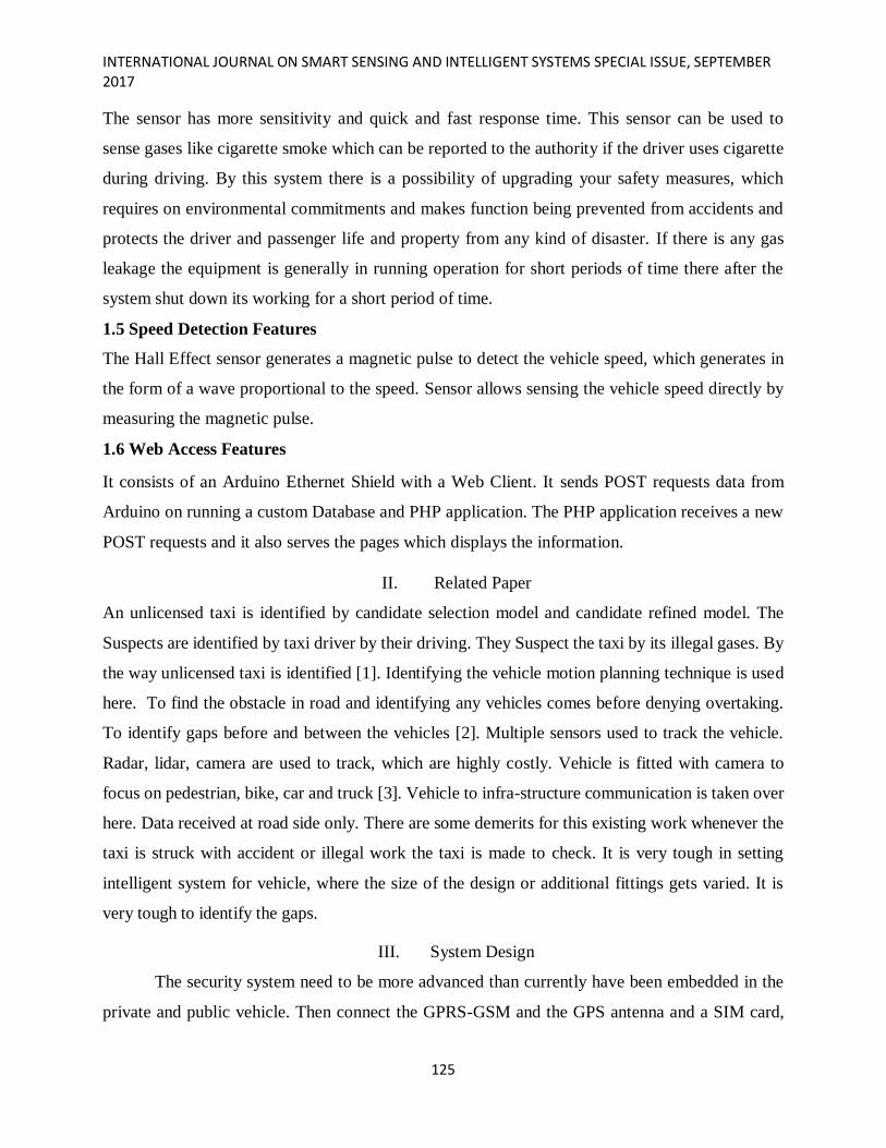
The Gas sensor contains 4pins. The first pin is power pin which requires 5V vcc and the second
pin is GND. The third pin is a digital output and the fourth pin is the analog output. It contains a
power indicating LED which displays after receiving input power supply. There is a sensitivity
control to adjust the sensitivity to find the gas. When the interfacing is done with the output to
Arduino, there glows an indicator LED in gas sensor to describe the flow and in fig 3.The
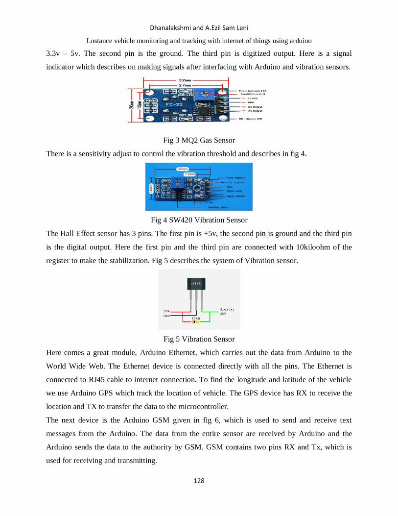
vibrating sensor which contains 3 pins: The first pin is vcc and the power supply ranges from
Dhanalakshmi and A.Ezil Sam Leni
Lnstance vehicle monitoring and tracking with internet of things using arduino
128
3.3v – 5v. The second pin is the ground. The third pin is digitized output. Here is a signal
indicator which describes on making signals after interfacing with Arduino and vibration sensors.
Fig 3 MQ2 Gas Sensor
There is a sensitivity adjust to control the vibration threshold and describes in fig 4.
Fig 4 SW420 Vibration Sensor
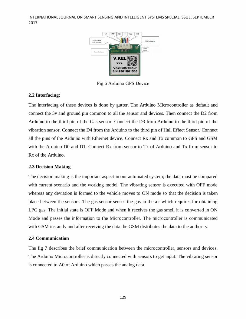
The Hall Effect sensor has 3 pins. The first pin is +5v, the second pin is ground and the third pin
is the digital output. Here the first pin and the third pin are connected with 10kiloohm of the
register to make the stabilization. Fig 5 describes the system of Vibration sensor.
Fig 5 Vibration Sensor
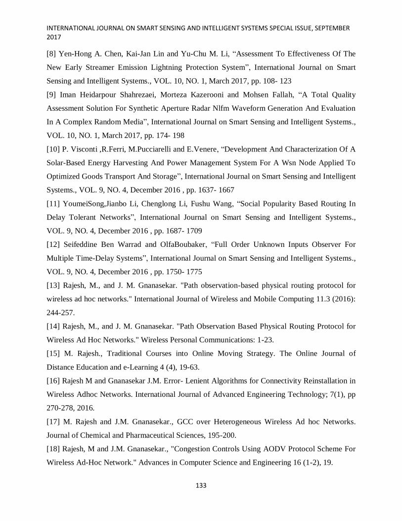
Here comes a great module, Arduino Ethernet, which carries out the data from Arduino to the
World Wide Web. The Ethernet device is connected directly with all the pins. The Ethernet is
connected to RJ45 cable to internet connection. To find the longitude and latitude of the vehicle
we use Arduino GPS which track the location of vehicle. The GPS device has RX to receive the
location and TX to transfer the data to the microcontroller.
The next device is the Arduino GSM given in fig 6, which is used to send and receive text
messages from the Arduino. The data from the entire sensor are received by Arduino and the
Arduino sends the data to the authority by GSM. GSM contains two pins RX and Tx, which is
used for receiving and transmitting.
INTERNATIONAL JOURNAL ON SMART SENSING AND INTELLIGENT SYSTEMS SPECIAL ISSUE, SEPTEMBER 2017
129
Fig 6 Arduino GPS Device
2.2 Interfacing:
The interfacing of these devices is done by gutter. The Arduino Microcontroller as default and
connect the 5v and ground pin common to all the sensor and devices. Then connect the D2 from
Arduino to the third pin of the Gas sensor. Connect the D3 from Arduino to the third pin of the
vibration sensor. Connect the D4 from the Arduino to the third pin of Hall Effect Sensor. Connect
all the pins of the Arduino with Ethernet device. Connect Rx and Tx common to GPS and GSM
with the Arduino D0 and D1. Connect Rx from sensor to Tx of Arduino and Tx from sensor to
Rx of the Arduino.
2.3 Decision Making
The decision making is the important aspect in our automated system; the data must be compared
with current scenario and the working model. The vibrating sensor is executed with OFF mode
whereas any deviation is formed to the vehicle moves to ON mode so that the decision is taken
place between the sensors. The gas sensor senses the gas in the air which requires for obtaining
LPG gas. The initial state is OFF Mode and when it receives the gas smell it is converted in ON
Mode and passes the information to the Microcontroller. The microcontroller is communicated
with GSM instantly and after receiving the data the GSM distributes the data to the authority.
2.4 Communication
The fig 7 describes the brief communication between the microcontroller, sensors and devices.
The Arduino Microcontroller is directly connected with sensors to get input. The vibrating sensor
is connected to A0 of Arduino which passes the analog data.

Dhanalakshmi and A.Ezil Sam Leni
Lnstance vehicle monitoring and tracking with internet of things using arduino
130
Fig 7 Communication between Microcontroller and other sensors
The Gas sensor is connected directly to the D0 of Arduino which passes Digital input to the
Microcontroller. Both the data is carried out to Microcontroller, where the GSM is connected
perfectly carries the data to the authority.
IV. Result and Discussion
The Rating of Gas Leakage sensor is derived after interfacing and configuration of all device and
sensors. The output is monitored by demonstrating the input values obtained from the sensors and
the output is performed by devices. Fig 8 describes about the working model of gas sensor which
is configured with Arduino and when there is any gas leakage, the gas sensor monitors and passes
its information to microcontroller which communicates with GSM and passes the message to the
authority.
Fig 8 Rating of Gas Leakage identified by sensor
The Fig 9 describes the current working of vibrating sensor that performs its work continuously.
The initial condition is OFF in mode when it receives some vibration it will be turned in to ON
mode and passes the information to authorities.

INTERNATIONAL JOURNAL ON SMART SENSING AND INTELLIGENT SYSTEMS SPECIAL ISSUE, SEPTEMBER 2017
131
Fig 9 Analyzing the mode of vibrating sensor
The Fig 10 describes the working of GSM Module where the data received from Gas Sensor or
Vibrating Sensor the GSM must act smart to send the information to the authority. The GSM is
required with a SIM card and the mobile number to which the data has to receive should be
given.
Fig 10 Working of GSM Module
V. Conclusion
The automatic detection of problems in a vehicle is termed perfectly and the configuration and
interfacing of the devices are made successfully. The microcontroller starts initially by getting the

Dhanalakshmi and A.Ezil Sam Leni
Lnstance vehicle monitoring and tracking with internet of things using arduino
132
sequential information from all the sensors and it acts as message passer via GSM and Ethernet.
The automated system is designed to find the gas leakage, vehicle vibration and makes proper
information.
REFERENCES
[1] Aizat Azmi, Ahmad Amsyar Azman, Sallehuddin Ibrahim, and Mohd Amri Md Yunus,
“Techniques In Advancing The Capabilities Of Various Nitrate Detection Methods: A Review”,
International Journal on Smart Sensing and Intelligent Systems., VOL. 10, NO. 2, June 2017, pp.
223-261.
[2] Tsugunosuke Sakai, Haruya Tamaki, Yosuke Ota, Ryohei Egusa, Shigenori Inagaki, Fusako
Kusunoki, Masanori Sugimoto, Hiroshi Mizoguchi, “Eda-Based Estimation Of Visual Attention
By Observation Of Eye Blink Frequency”, International Journal on Smart Sensing and Intelligent
Systems., VOL. 10, NO. 2, June 2017, pp. 296-307.
[3] Ismail Ben Abdallah, Yassine Bouteraa, and Chokri Rekik , “Design And Development Of 3d
Printed Myoelctric Robotic Exoskeleton For Hand Rehabilitation”, International Journal on
Smart Sensing and Intelligent Systems., VOL. 10, NO. 2, June 2017, pp. 341-366.
[4] S. H. Teay, C. Batunlu and A. Albarbar, “Smart Sensing System For Enhanceing The
Reliability Of Power Electronic Devices Used In Wind Turbines”, International Journal on Smart
Sensing and Intelligent Systems., VOL. 10, NO. 2, June 2017, pp. 407- 424
[5] SCihan Gercek, Djilali Kourtiche, Mustapha Nadi, Isabelle Magne, Pierre Schmitt, Martine
Souques and Patrice Roth, “An In Vitro Cost-Effective Test Bench For Active Cardiac Implants,
Reproducing Human Exposure To Electric Fields 50/60 Hz”, International Journal on Smart
Sensing and Intelligent Systems., VOL. 10, NO. 1, March 2017, pp. 1- 17
[6] P. Visconti, P. Primiceri, R. de Fazio and A. Lay Ekuakille, “A Solar-Powered White Led-
Based Uv-Vis Spectrophotometric System Managed By Pc For Air Pollution Detection In
Faraway And Unfriendly Locations”, International Journal on Smart Sensing and Intelligent
Systems., VOL. 10, NO. 1, March 2017, pp. 18- 49
[7] Samarendra Nath Sur, Rabindranath Bera and Bansibadan Maji, “Feedback Equalizer For
Vehicular Channel”, International Journal on Smart Sensing and Intelligent Systems., VOL. 10,
NO. 1, March 2017, pp. 50- 68
INTERNATIONAL JOURNAL ON SMART SENSING AND INTELLIGENT SYSTEMS SPECIAL ISSUE, SEPTEMBER 2017
133
[8] Yen-Hong A. Chen, Kai-Jan Lin and Yu-Chu M. Li, “Assessment To Effectiveness Of The
New Early Streamer Emission Lightning Protection System”, International Journal on Smart
Sensing and Intelligent Systems., VOL. 10, NO. 1, March 2017, pp. 108- 123
[9] Iman Heidarpour Shahrezaei, Morteza Kazerooni and Mohsen Fallah, “A Total Quality
Assessment Solution For Synthetic Aperture Radar Nlfm Waveform Generation And Evaluation
In A Complex Random Media”, International Journal on Smart Sensing and Intelligent Systems.,
VOL. 10, NO. 1, March 2017, pp. 174- 198
[10] P. Visconti ,R.Ferri, M.Pucciarelli and E.Venere, “Development And Characterization Of A
Solar-Based Energy Harvesting And Power Management System For A Wsn Node Applied To
Optimized Goods Transport And Storage”, International Journal on Smart Sensing and Intelligent
Systems., VOL. 9, NO. 4, December 2016 , pp. 1637- 1667
[11] YoumeiSong,Jianbo Li, Chenglong Li, Fushu Wang, “Social Popularity Based Routing In
Delay Tolerant Networks”, International Journal on Smart Sensing and Intelligent Systems.,
VOL. 9, NO. 4, December 2016 , pp. 1687- 1709
[12] Seifeddine Ben Warrad and OlfaBoubaker, “Full Order Unknown Inputs Observer For
Multiple Time-Delay Systems”, International Journal on Smart Sensing and Intelligent Systems.,
VOL. 9, NO. 4, December 2016 , pp. 1750- 1775
[13] Rajesh, M., and J. M. Gnanasekar. "Path observation-based physical routing protocol for
wireless ad hoc networks." International Journal of Wireless and Mobile Computing 11.3 (2016):
244-257.
[14] Rajesh, M., and J. M. Gnanasekar. "Path Observation Based Physical Routing Protocol for
Wireless Ad Hoc Networks." Wireless Personal Communications: 1-23.
[15] M. Rajesh., Traditional Courses into Online Moving Strategy. The Online Journal of
Distance Education and e-Learning 4 (4), 19-63.
[16] Rajesh M and Gnanasekar J.M. Error- Lenient Algorithms for Connectivity Reinstallation in
Wireless Adhoc Networks. International Journal of Advanced Engineering Technology; 7(1), pp
270-278, 2016.
[17] M. Rajesh and J.M. Gnanasekar., GCC over Heterogeneous Wireless Ad hoc Networks.
Journal of Chemical and Pharmaceutical Sciences, 195-200.
[18] Rajesh, M and J.M. Gnanasekar., "Congestion Controls Using AODV Protocol Scheme For
Wireless Ad-Hoc Network." Advances in Computer Science and Engineering 16 (1-2), 19.

Dhanalakshmi and A.Ezil Sam Leni
Lnstance vehicle monitoring and tracking with internet of things using arduino
134
[19] Rajesh M, Gnanasekar J. M. Sector Routing Protocol (SRP) in Ad-hoc Networks, Control
Network and Complex Systems 5 (7), 1-4, 2015.
[20] Rajesh M, Gnanasekar J. M. Routing and Broadcast Development for Minimizing
Transmission Interruption in Multi rate Wireless Mesh Networks using Directional Antennas,
Innovative Systems Design and Engineering 6 (7), 30-42.
[21] Annibalepanichella,Rocco oliveto,Massimiliano Di Penta,Andrea De Lucia, “ Improving
multi-objective test case Selection by Injecting Diversity in genetic Algorithms”, IEEE
Transactions on Software Engineering,pp.358-383,Vol.41,No.4,April 2015.
[22] Zhang Hui, “Fault Localization Method Generated by Regression Test Cases on the Basis of
Genetic Immune Algorithm”, In: proc. Of IEEE conference on Annual International Computers,
Software & Applications Conference, pp. 46-51, 2016.
[23] S. Yoo and M. Harman, “Regression testing minimization, selectionand prioritization: A
survey,” Softw. Test. Verif. Rel., vol. 22,no. 2, pp. 67–120, Mar. 2012.
[24] S. Yoo, “A novel mask-coding representation for set cover problemswith applications in test
suite minimisation,” In: Proc. of 2nd International Symposium. Search-Based Software. Eng.,
2010, pp. 19–28.
[25] S. Yoo and M. Harman, “Pareto efficient multi-objective test case selection,” In: Proc. of
ACM /SIGSOFT Int. Symp. Softw. Testing Anal.,2007, pp. 140–150.
[26] S. Yoo and M. Harman, “Using hybrid algorithm for Pareto efficientmulti-objective test
suite minimisation,” J. Syst. Softw.,vol. 83, no. 4, pp. 689–701, 2010.
[27] S. Yoo, M. Harman, and S. Ur, “Highly scalable multi objectivetest suite minimization using
graphics cards,” In:Proc. of 3rd Int.Conf. Search Based Softw. Eng., 2011, pp. 219–236.
[28] Q. Zhang and Y.-W. Leung, “An orthogonal genetic algorithm for multimedia multicast
routing,” IEEE Trans. Evol. Comput., vol. 3,no. 1, pp. 53–62, Apr. 1999.
[29] J. Zhu, G. Dai, and L. Mo, “A cluster-based orthogonal multi objective genetic algorithm”,
Comput. Intell. Intell. Syst., vol. 51,pp. 45–55, 2009.
[30] E. Zitzler, D. Brockhoff, and L. Thiele, “The hypervolume indicatorrevisited: On the design
of Pareto-compliant indicators via weighted integration”,In: Proc. of 4th Int. Conf. Evol. Multi-
CriterionOptim., 2007, pp. 862–876.

INTERNATIONAL JOURNAL ON SMART SENSING AND INTELLIGENT SYSTEMS SPECIAL ISSUE, SEPTEMBER 2017
135
[31] Jones JA, Harrold MJ. “Empirical Evaluation of the Tarantula Automatic Fault -
Localization Technique”. In: Proc. of 20th IEEE/ ACM International Conference on Automated
Software Engineering, 2005: 273-282.
[32] Jones JA, Harrold MJ, Stasko J. “Visualization of Test Information to Assist Fault
Localization”.In: Proc. ofthe 24th International Conference on Software Engineering, 2002:467-
477.