installers guide side return kit baysrkit100a...
TRANSCRIPT

Side Return Kit:BAYSRKIT100A for 1-1/2 - 5 Ton Air Handler Installations
INSTALLER'SGUIDE
IMPORTANT — This Document is customer property and is to remain with this unit. Please return to service information pack upon completion of work.
© 2010 Trane
ALL phases of this installation must comply with NATIONAL, STATE AND LOCAL CODES
18-GJ13D1-1
08/10
Fits Models:
HyperionTM and ForeFrontTM Air Handlers
Section 1. Safety Information
▲ WARNING!SAFETY HAzARD! This information is intended for use by individuals possessing adequate backgrounds of electrical and mechanical experience. Any attempt to repair a central air conditioning product may result in personal injury and/or property damage. The manufacturer or seller cannot be responsible for the interpretation of this information, nor can it assume any liability in connection with its use.
LIVE ELECTRICAL COMPONENTS! During in-stallation, testing, servicing, and troubleshooting of this product, it may be necessary to work with live electrical components. Failure to follow all electrical safety precautions when exposed to live electrical components could result in death or serious injury.
▲ WARNING!
Section 2. General Information
Open and inspect contents for damage or missing items.
Each kit will contain:
Item Qty Description1 1 Plate Assembly2 1 Template3 2 Long Flange4 2 Short Flange5 8 10-32 Serrated Nut6 1 Bottom Return Block-off Plate7 1 Double Sided Foam Tape8 1 Installer's Guide
▲ WARNING!SAFETY HAzARD! Sharp Edge Hazard. Be careful of sharp edges on equipment or any cuts made on sheet metal while installing or servicing. Personal injury may result.
12
3 4
56
The inside duct opening for the side return kit is: 11 inches tall15.5 inches deep
▲ CAUTION!SAFETY HAzARD! Cutting and removal of air handler cabinet materials for the side return kit for HyperionTM and ForeFrontTM Air Handlers may result in debris being released into the air. PPE (Personal Protection Equipment) equipment for protection of the eyes, mouth, and nose is recommended for cutting and removal of air handler cabinet materials for the side return kit.
Page 2
INSTALLER'S GUIDE
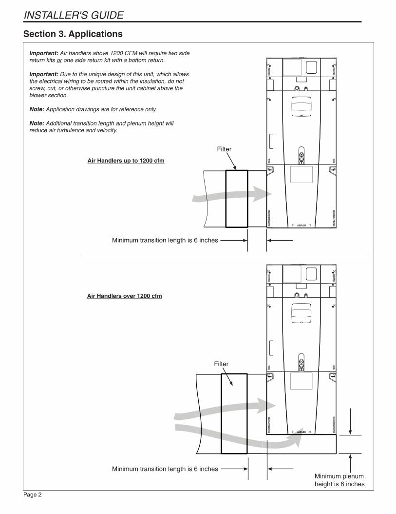
Section 3. Applications
Important: Air handlers above 1200 CFM will require two side return kits or one side return kit with a bottom return.
Important: Due to the unique design of this unit, which allows the electrical wiring to be routed within the insulation, do not screw, cut, or otherwise puncture the unit cabinet above the blower section.
Note: Application drawings are for reference only.
Note: Additional transition length and plenum height will reduce air turbulence and velocity.
Minimum transition length is 6 inches
Filter
Minimum plenum height is 6 inches
Air Handlers up to 1200 cfm
Air Handlers over 1200 cfm
Filter
Minimum transition length is 6 inches

Page 3
INSTALLER'S GUIDE
Section 4. Installation
Note: The side return kit should be installed before installing the air handler.
STEP 1 - Set the air handler in an open environment that provides plenty of room to install the kit.
STEP 2 - Evaluate the install application and determine which side of the air handler the return duct will enter. Make a mark on the side of the blower to identify this.
STEP 3 - Remove blower panel once the proper side is noted.
The Blower/Filter panel is removed using 1/4 turn thumb screws.
1. Turn thumb screws on Blower/Filter panel.
2. Pull top of panel out, away from cabinet.
3. Lift panel up out of channel.
4. Set aside.

Page 4
INSTALLER'S GUIDE
Blower Electrical Connections
STEP 4 - Remove the blower by first disconnecting the two wiring connections routed to the blower assembly.
STEP 3 - Slide Blower assembly out of unit using built-in blower support channels and set aside.
Find a location where the air handler can be placed on its side without scratching or damaging the cabinet. Set the template on the side of the blower panel. The inside of the template must be 4-3/4" from the bottom and 3-3/4" from the back of the air handler.
The template must be square. Use a marker if needed to outline measurements.
4.75”
3.75”

Page 5
INSTALLER'S GUIDE
Use a felt pen to mark the 8 holes in the template.
Use a 1/4 inch bit to drill each of the 8 points. The drill must be perpendicular to the air handler. The plate assembly will not fit through the holes if they are drilled in at an angle.

Page 6
INSTALLER'S GUIDE
Set the plate assembly with the 8 studs on the outer side of the cabinet so the bolts penetrate through the cabinet.
Important: The plate assembly and template must be tight and secure to provide a clean cut through the cabinet.
Place the template over the studs and secure with the nuts provided.

Page 7
INSTALLER'S GUIDE
STEP 5 - Drill out the three holes located on each side of the template
STEP 6 - Starting at the pilot holes, use a reciprocating saw and cut out template.
Caution: Evaluate the hole and remove any sharp edges or burrs generated by the saw blade.

Page 8
INSTALLER'S GUIDE
STEP 7 - Loosen the nuts and set the four flanges in place to cover the inner cabinet insulation.
Tighten the nuts two full turns past finger tight.Flange Install- Typical

Page 9
INSTALLER'S GUIDE
STEP 2 - Wipe the block-off plate to remove any debris.
STEP 3 - Cut the double-sided foam tape to fit the plate. The tape must be flush to the outer edge of the block-off plate.
STEP 4 - Wipe the bottom of the air handler to ensure it is clean.
Section 5. Bottom Return Block-off Plate Installation
Note: The bottom return block-off plate may be used to seal the base of the air handler for side return only applications.
STEP 1 - Cut the bottom block off plate to the appropriate size for A and B cabinets. No change is needed for the C size cabinet (23.5").
21.3
Detail A
ACabinet
BCabinet
CCabinet
(no cut required)
Detail A(4 Places)
23.5
20.2
17.5
Cabinet Size
Plate Height
Plate Width
A 20.2 17.5
B 20.2 21.3
C 20.2 23.5

Page 10
INSTALLER'S GUIDE
STEP 5 - Attach the plate to the bottom of the air handler. Press firmly to make sure the double-sided tape adheres to the air handler.
STEP 6 -Place the air handler in the installa-tion location and attach return duct to the air handler cabinet. Secure and seal the duct work to the air handler per local codes.

Page 11
INSTALLER'S GUIDE

Since the manufacturer has a policy of continuous product and product data improvement, it reserves the right to change design and specification without notice.
Trane6200 Troup HighwayTyler, TX 75707