installers guide for residential...
TRANSCRIPT

Installers Guide for Residential ConstructionBuilders will find all aspects of using LSB to be surprisingly easy

2
Tab
le o
f C
on
ten
ts Section Page
Introduction . . . . . . . . . . . . . . . . . . . . . . . . . . . . . . . .3
LSB Sizes and Dimensions . . . . . . . . . . . . . . . . . . . .4
Properties, Flexural, and Shear Strength . . . . . . . .5
Span Table, 1 Floor . . . . . . . . . . . . . . . . . . . . . . . . . .6
Span Table, 2 Floors . . . . . . . . . . . . . . . . . . . . . . . . .7
Load Tables . . . . . . . . . . . . . . . . . . . . . . . . . . . . . . . . .8
2 x 4 Header Connection . . . . . . . . . . . . . . . . . . . . . .9
Attaching Services to LSB . . . . . . . . . . . . . . . . . . .10
Wall Connections . . . . . . . . . . . . . . . . . . . . . . . . . . .11
Column Connections . . . . . . . . . . . . . . . . . . . . . . . .12
Other Typical Connections . . . . . . . . . . . . . . . . . . .13
Cutting LSB . . . . . . . . . . . . . . . . . . . . . . . . . . . . . . .14
Screwing LSB . . . . . . . . . . . . . . . . . . . . . . . . . . . . . .15
Drilling LSB . . . . . . . . . . . . . . . . . . . . . . . . . . . . . . . .16
Bolting LSB . . . . . . . . . . . . . . . . . . . . . . . . . . . . . . . .17
Fastening Wood Floor Sheath Using Nails . . . . . .18
Welding LSB . . . . . . . . . . . . . . . . . . . . . . . . . . . . . . .19
Painting LSB . . . . . . . . . . . . . . . . . . . . . . . . . . . . . . .20
Using LSB Back-to-Back . . . . . . . . . . . . . . . . . . . .21
Stiffeners . . . . . . . . . . . . . . . . . . . . . . . . . . . . . . . . . .22
10127 LSB cover:Layout 1 1/7/09 3:57 PM Page 2

IntroductionLiteSteel™ Beam (LSB®) from LiteSteel Technologies was developed in response to the demand for a lightstructural beam with the strength of steel but with theworkability and ease of installation associated with wood products. When you weigh up the problemsinvolved with hot rolled structural steel beams and engineered wood beams, LSB can providesignificant time and installation cost advantages. The innovative, patented cold forming process givesLSB a unique profile with the torsional rigidity you would normally expect from hot rolled steel. It can be carried like a wood beam and can be cut, nailed,screwed, and drilled on site using the same tools you currently use. LSB is supplied with a G-60 orequivalent coating for superior corrosion protection.
Working with LSBLiteSteel beam is on average 40% lighter than hot rolled steel and engineered wood beams of equivalentperformance. It is easier to lift and carry and can behoisted without the need for a crane. Installing LSB doesnot require any new tools or radical building methods.You can install it and work with it like you would with awood beam. Fit the recommended saw blades, drill bits,screws, and nails and installation is easy. Connections towood components are simple using standard Simpsonor USP wood construction connectors.
LSB can be used in place of other structural beams;wood or steel. Choosing LSB gives you an advantagefor a number of load bearing applications includingbasement beams, garage beams, ridge beams, long span headers, floor and deck supports, andmezzanine flooring. The information in this InstallersGuide for Residential Construction is meant to providegeneral advice and recommendations for working withLSB. For further information and technical support call us at 1-877-285-2607 or visit our web sitewww.LiteSteelbeam.com.
A Structural Beam with theStrength of Steel and theInstallation Ease of Wood
3
StrengthMeets
Versatility

Dimensionsd b df t
LSB Product Code Weight Beam Depth Flange Width Flange Thickness Metal Thickness
lb/ft in in in in
1400LSB350-134 13.07 13.8 3.50 1.18 0.134
1400LSB350-118 11.59 13.8 3.50 1.18 0.118
1400LSB350-98 9.73 13.8 3.50 1.18 0.098
1200LSB350-134 12.17 11.8 3.50 1.18 0.134
1200LSB350-118 10.80 11.8 3.50 1.18 0.118
1200LSB350-98 9.07 11.8 3.50 1.18 0.098
1000LSB300-118 8.97 9.8 2.95 0.98 0.118
1000LSB300-98 7.54 9.8 2.95 0.98 0.098
1000LSB300-79 6.09 9.8 2.95 0.98 0.079
800LSB250-98 5.96 7.9 2.36 0.79 0.098
800LSB250-79 4.82 7.9 2.36 0.79 0.079
800LSB250-59 3.67 7.9 2.36 0.79 0.059
US 50 ksi steelUS Imperial
1000LSB300-98LSB Product Code...
LiteSteel™ beam Sizes and Dimensions
Beam Sizes
4
Beam depth (nominal) inhundredths of an inch (eg, 1000=10 inches)
Beam shape code Beam flange width(nominal) in hundredths
of an inch
Steel material thicknessin mils (thousandths of
an inch)
dL R
df
t
b
5
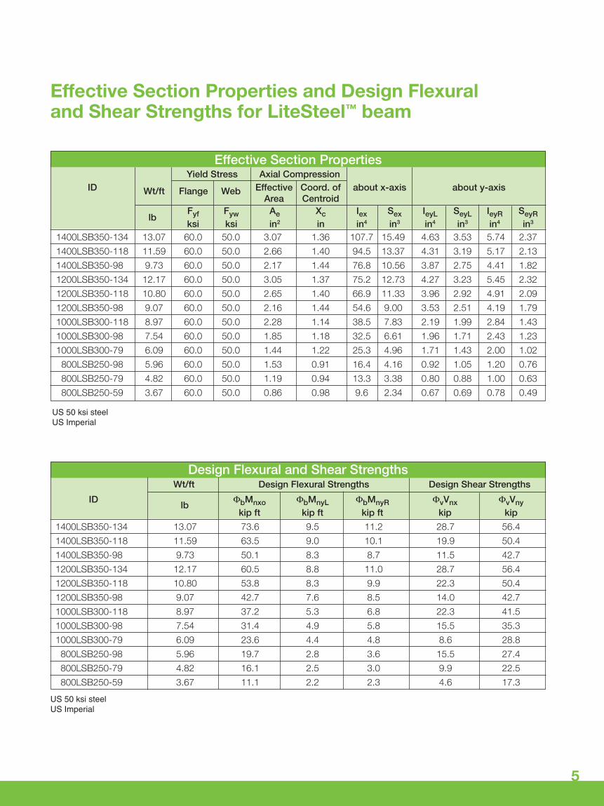
Effective Section Properties and Design Flexural and Shear Strengths for LiteSteel™ beam
Effective Section PropertiesYield Stress Axial Compression
ID Wt/ft Flange Web Effective Coord. of about x-axis about y-axisArea Centroid
lbFyf Fyw Ae Xc Iex Sex IeyL SeyL IeyR SeyRksi ksi in2 in in4 in3 in4 in3 in4 in3
1400LSB350-134 13.07 60.0 50.0 3.07 1.36 107.7 15.49 4.63 3.53 5.74 2.37
1400LSB350-118 11.59 60.0 50.0 2.66 1.40 94.5 13.37 4.31 3.19 5.17 2.13
1400LSB350-98 9.73 60.0 50.0 2.17 1.44 76.8 10.56 3.87 2.75 4.41 1.82
1200LSB350-134 12.17 60.0 50.0 3.05 1.37 75.2 12.73 4.27 3.23 5.45 2.32
1200LSB350-118 10.80 60.0 50.0 2.65 1.40 66.9 11.33 3.96 2.92 4.91 2.09
1200LSB350-98 9.07 60.0 50.0 2.16 1.44 54.6 9.00 3.53 2.51 4.19 1.79
1000LSB300-118 8.97 60.0 50.0 2.28 1.14 38.5 7.83 2.19 1.99 2.84 1.43
1000LSB300-98 7.54 60.0 50.0 1.85 1.18 32.5 6.61 1.96 1.71 2.43 1.23
1000LSB300-79 6.09 60.0 50.0 1.44 1.22 25.3 4.96 1.71 1.43 2.00 1.02
800LSB250-98 5.96 60.0 50.0 1.53 0.91 16.4 4.16 0.92 1.05 1.20 0.76
800LSB250-79 4.82 60.0 50.0 1.19 0.94 13.3 3.38 0.80 0.88 1.00 0.63
800LSB250-59 3.67 60.0 50.0 0.86 0.98 9.6 2.34 0.67 0.69 0.78 0.49
Design Flexural and Shear StrengthsWt/ft Design Flexural Strengths Design Shear Strengths
ID ΦbMnxo ΦbMnyL ΦbMnyR ΦvVnx ΦvVnylbkip ft kip ft kip ft kip kip
1400LSB350-134 13.07 73.6 9.5 11.2 28.7 56.4
1400LSB350-118 11.59 63.5 9.0 10.1 19.9 50.4
1400LSB350-98 9.73 50.1 8.3 8.7 11.5 42.7
1200LSB350-134 12.17 60.5 8.8 11.0 28.7 56.4
1200LSB350-118 10.80 53.8 8.3 9.9 22.3 50.4
1200LSB350-98 9.07 42.7 7.6 8.5 14.0 42.7
1000LSB300-118 8.97 37.2 5.3 6.8 22.3 41.5
1000LSB300-98 7.54 31.4 4.9 5.8 15.5 35.3
1000LSB300-79 6.09 23.6 4.4 4.8 8.6 28.8
800LSB250-98 5.96 19.7 2.8 3.6 15.5 27.4
800LSB250-79 4.82 16.1 2.5 3.0 9.9 22.5
800LSB250-59 3.67 11.1 2.2 2.3 4.6 17.3
US 50 ksi steelUS Imperial
US 50 ksi steelUS Imperial

6
Joist Span A
Joist Span B
LSB® Span
LSB® Central Support Beam
Joists
Tributary Span = (Span A + Span B) / 2
LSB® Span Table, Central Beam Supporting 1 Floor
Notes:Deflection Limit: L/360 for live loads and L/240 for total loadsWeb stiffeners are required at supports, otherwise web crippling shall be checkedLSB is assumed to have full lateral support. If no lateral restraint, distortional buckling shall be checkedFloor live load is 40 psfFloor dead load is 15 psf
Nominal Nominal Metal LSB LSB Beam Span, Feet
Beam Flange Thickness Weight Center Beam Supporting One FloorDepth Width (thousandths per foot ID
(inches) (inches) of an inch) of Length Tributary Span, Feet
(pounds) 8 10 12 14 16 18 20 22 2414 3.5 134 13.07 1400LSB350-134 27.5 25.5 24.0 22.8 21.8 21.0 20.3 19.6 19.114 3.5 118 11.59 1400LSB350-118 26.3 24.4 23.0 21.9 20.9 20.1 19.4 17.8 16.314 3.5 98 9.73 1400LSB350-98 24.6 22.7 18.9 16.2 14.2 12.6 11.3 10.3 9.412 3.5 134 12.17 1200LSB350-134 24.4 22.7 21.3 20.3 19.4 18.6 18.0 17.4 16.912 3.5 118 10.80 1200LSB350-118 23.5 21.8 20.5 19.5 18.6 17.9 17.3 16.8 16.312 3.5 98 9.07 1200LSB350-98 21.9 20.4 19.2 18.2 17.2 15.3 13.8 12.5 11.510 3.0 118 8.97 1000LSB300-118 19.5 18.1 17.1 16.2 15.5 14.9 14.4 13.9 13.510 3.0 98 7.54 1000LSB300-98 18.5 17.1 16.1 15.3 14.6 14.1 13.6 13.2 12.710 3.0 79 6.09 1000LSB300-79 17.0 15.8 14.2 12.1 10.6 9.4 8.5 7.7 7.18 2.5 98 5.96 800LSB250-98 14.7 13.6 12.8 12.2 11.7 11.2 10.8 10.5 10.28 2.5 79 4.82 800LSB250-79 13.7 12.7 12.0 11.4 10.9 10.5 9.7 8.9 8.18 2.5 59 3.67 800LSB250-59 11.3 9.1 7.5 6.5 5.7 5.0 4.5 4.1 3.8
Continuous Beam–One Story Loading

7
Nominal Nominal Metal LSB LSB Beam Span, Feet
Beam Flange Thickness Weight Center Beam Supporting Two FloorsDepth Width (thousandths per foot ID
(inches) (inches) of an inch) of Length Tributary Span, Feet
(pounds) 8 10 12 14 16 18 20 22 2414 3.5 134 13.07 1400LSB350-134 21.8 20.3 19.1 18.1 17.1 15.7 14.1 12.8 11.814 3.5 118 11.59 1400LSB350-118 20.9 19.4 16.3 14.0 12.2 10.9 9.8 8.9 8.214 3.5 98 9.73 1400LSB350-98 14.2 11.3 9.4 8.1 7.1 6.3 5.7 5.2 4.712 3.5 134 12.17 1200LSB350-134 19.4 18.0 16.9 16.1 15.4 14.6 13.9 12.8 11.812 3.5 118 10.80 1200LSB350-118 18.6 17.3 16.3 15.5 13.7 12.2 11.0 10.0 9.112 3.5 98 9.07 1200LSB350-98 17.2 13.8 11.5 9.8 8.6 7.6 6.9 6.3 5.710 3.0 118 8.97 1000LSB300-118 15.5 14.4 13.5 12.9 12.2 11.5 10.9 10.0 9.110 3.0 98 7.54 1000LSB300-98 14.6 13.6 12.7 10.9 9.5 8.5 7.6 6.9 6.310 3.0 79 6.09 1000LSB300-79 10.6 8.5 7.1 6.1 5.3 4.7 4.2 3.9 3.58 2.5 98 5.96 800LSB250-98 11.7 10.8 10.2 9.5 8.9 8.4 7.6 6.9 6.38 2.5 79 4.82 800LSB250-79 10.9 9.7 8.1 7.0 6.1 5.4 4.9 4.4 4.18 2.5 59 3.67 800LSB250-59 5.7 4.5 3.8 3.2 2.8 2.5 2.3 2.1 1.9
Notes:Deflection Limit: L/360 for live loads and L/240 for total loadsWeb stiffeners are required at supports, otherwise web crippling shall be checkedLSB is assumed to have full lateral support. If no lateral restraint, distortional buckling shall be checkedFloor live loads–first floor 40 psf; second floor 40 psfFloor dead loads–first floor 15 psf; second floor 15 psf
LSB® Span Table, Central Beam Supporting 2 Floors(second floor not shown)
Joist Span A
Joist Span B
LSB® Span
LSB® Central Support Beam
Joists
Tributary Span = (Span A + Span B) / 2
Continuous Beam–Two Story Loading

8
LSB® Load Tables
Notes:Deflection Limit: L/360 for live loads and L/240 for total loadsWeb stiffeners are required at supports, otherwise web crippling shall be checked.LSB is assumed to have full lateral support. If no lateral restraint, distortional buckling shall be checked.
Live Load Deflection L/360
Total Load (lbs/ft) Most Restrictive Simple Beam or Continuous Span
Total Load = 75%LL + 25%DL
Beam Size Deflection = < Live Load/360 Deflection = < Total Load/240
Beam Span, Feet
4 6 8 10 12 14 16 18 20 24 28 32
1400LSB350-134 7649 5099 3824 3059 2550 2023 1549 1088 793 459 289 194
1400LSB350-118 5291 3527 2645 2116 1764 1512 1323 967 705 408 257 172
1400LSB350-98 3031 2020 1515 1212 1010 866 758 673 583 338 213 142
1200LSB350-134 7649 5099 3824 3059 2287 1627 1090 765 558 323 203 136
1200LSB350-118 5940 3960 2970 2376 1980 1421 952 668 487 282 178 119
1200LSB350-98 3689 2460 1845 1476 1230 1054 797 560 408 236 149 100
1000LSB300-118 5940 3960 2970 1958 1281 807 541 380 277 160 101 68
1000LSB300-98 4097 2731 2049 1632 1096 690 462 325 237 137 86 58
1000LSB300-79 2339 1559 1170 936 780 522 350 246 179 104 65 44
800LSB250-98 4097 2731 1647 956 553 348 233 164 119 69 44
800LSB250-79 2662 1775 1331 775 449 282 189 133 97 56
800LSB250-59 1218 812 609 487 334 210 141 99 72 42
Notes:Deflection Limit: L/480 for live loads and L/240 for total loadsWeb stiffeners are required at supports, otherwise web crippling shall be checked.LSB is assumed to have full lateral support. If no lateral restraint, distortional buckling shall be checked.
Live Load Deflection L/480
Total Load (lbs/ft) Most Restrictive Simple Beam or Continuous Span
Total Load = 75%LL + 25%DL
Beam Size Deflection = < Live Load/480 Deflection = < Total Load/240
Beam Span, Feet
4 6 8 10 12 14 16 18 20 24 28 32
1400LSB350-134 7649 5099 3824 3059 2550 1734 1162 816 595 344 217 145
1400LSB350-118 5291 3527 2645 2116 1764 1512 1033 725 529 306 193 129
1400LSB350-98 3031 2020 1515 1212 1010 866 758 600 438 253 159 107
1200LSB350-134 7649 5099 3824 3059 1937 1220 817 574 418 242 153 102
1200LSB350-118 5940 3960 2970 2376 1692 1066 714 501 365 212 133 89
1200LSB350-98 3689 2460 1845 1476 1230 892 598 420 306 177 111 75
1000LSB300-118 5940 3960 2970 1661 961 605 405 285 208 120 76 51
1000LSB300-98 4097 2731 2049 1420 822 518 347 244 178 103 65 43
1000LSB300-79 2339 1559 1170 936 622 392 262 184 134 78 49
800LSB250-98 4097 2731 1400 717 415 261 175 123 90 52
800LSB250-79 2662 1775 1135 581 336 212 142 100 73
800LSB250-59 1218 812 609 433 250 158 106 74 54

9
Quick Tips
2 x 4 Wood Plate Connection to LSB® Flange
2 x 4 Plates Bolted 2 x 4 Plates Screwed
Wood plates can be bolted to LSB
• Clamp 2 x 4 wood plate to flange of LSB.
• Drill a 9/16˝ diameter hole through the wood plate and the LSB flange at each bolt location.
• Bolt wood plate to LSB flange with 1/2˝ bolts. A washer is required under both the head and the nut of the bolt.
Self-drilling screws (SDS) can be used to fix wood plates to LSB
• Clamp wood plate to LSB.
• Connect the wood plate to the LSB using screws.
• Winged SDS, counter-sunk SDS and hex head SDS can be used. Minimum of three full threads should protrude through the steel. The tip of the screw should not touch the second flange. Drill speed of 2500 rpm is typically required for drilling SDS screw types.
• Nailer plate connections should be roughly every two feet on center.
Screw selection is important. The screw drillpoint requires a drill and tap capacity that mustbe greater than the material thickness (t). Thelength of the drill point and three threads must beless than the flange void height (df-2xt). Refer tothe table on page 4 for values of df and t for eachLSB size. The length of the screw must be longenough that the drill point and three threadsprotrude through the first skin of the LSB flange,however not so long that the drill point hits thesecond skin of the LSB flange.
When pre-drilling wood plate, ensure the holethrough the wood is clear of burrs and larger thanthe diameter of the screw.
Firm, consistent pressure and speed is required.
Quality of screws vary widely. Test screws on an off-cut of LSB prior to use to ensure they are suitable.
The most efficient way to work with the LSB is to do as much preparation as possible while it is still onthe ground before lifting it into place. Fit the nailingplate to the LSB before lifting the beam into place.
Wood Plate
LSB Flange
Wood Plate
LSB Flange

10
Electrical and mechanical services can be attachedto LSB.
Common wiring and tube clamps can be fixeddirectly to the LSB flange or web using self-drillingscrews, rivets or bolts. The C profile of LSB providesa convenient space for running pipes and wiring.
When fixing metal pipe to LSB, check materialcompatibility of the tube with galvanized steel andprovide isolation where required. In particular, copper products should never be in contact withgalvanized steel.
#10-16 x 3/4˝ self-drilling screws with #3 drill pointare suitable for fixing COL0X07Z1 KMC clamps.
Attaching Services to LSB®
Services can be concealedwithin the LSB profile

Wall Connections
LSB® to Pocket in Concrete Wall
• 2 x 4˝ wood top plate fixed with #12-24 x 2-1/4˝ winged self-drilling screws (Buildex® Part Number 1092000) to LSB top plate.
• Simpson LSTA21 across wood top plate to mudsill/wall frame.
• Moisture barrier may be required per local code.
LSB to Pocket in Concrete Wall with Uplift Resistance
• Simpson Heta16 with 10058P3 Drivall self-drilling screws.
• 2 x 4˝ wood top plate fixed with #12-24 x 2-1/4˝ winged self-drilling screws to LSB top plate.
• Simpson LSTA21 across wood top plate to mudsill/wall frame.
• Moisture barrier may be required per local code.
11
12
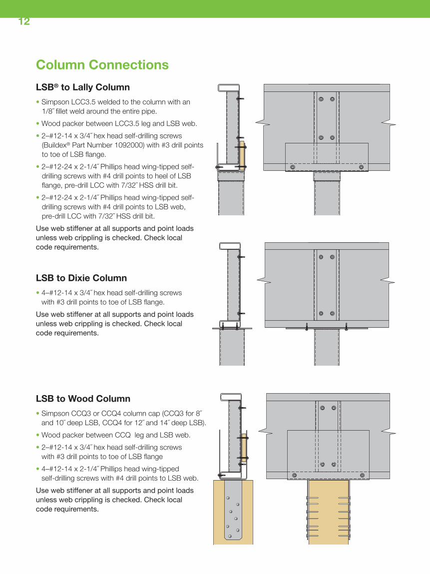
LSB to Wood Column
• Simpson CCQ3 or CCQ4 column cap (CCQ3 for 8˝ and 10˝ deep LSB, CCQ4 for 12˝ and 14˝ deep LSB).
• Wood packer between CCQ leg and LSB web.
• 2–#12-14 x 3/4˝ hex head self-drilling screws with #3 drill points to toe of LSB flange
• 4–#12-14 x 2-1/4˝ Phillips head wing-tippedself-drilling screws with #4 drill points to LSB web.
Use web stiffener at all supports and point loadsunless web crippling is checked. Check local code requirements.
Column Connections
LSB® to Lally Column
• Simpson LCC3.5 welded to the column with an 1/8˝ fillet weld around the entire pipe.
• Wood packer between LCC3.5 leg and LSB web.
• 2–#12-14 x 3/4˝ hex head self-drilling screws (Buildex® Part Number 1092000) with #3 drill points to toe of LSB flange.
• 2–#12-24 x 2-1/4˝ Phillips head wing-tipped self-drilling screws with #4 drill points to heel of LSB flange, pre-drill LCC with 7/32˝ HSS drill bit.
• 2–#12-24 x 2-1/4˝ Phillips head wing-tipped self-drilling screws with #4 drill points to LSB web,pre-drill LCC with 7/32˝ HSS drill bit.
Use web stiffener at all supports and point loadsunless web crippling is checked. Check local code requirements.
LSB to Dixie Column
• 4–#12-14 x 3/4˝ hex head self-drilling screws with #3 drill points to toe of LSB flange.
Use web stiffener at all supports and point loadsunless web crippling is checked. Check local code requirements.

13
Other Typical Connections Using LSB®
LSB does not require special connectors. SimpsonStrong-Tie, USP and others manufacture a wide rangeof code approved construction connectors suitable foruse with LSB.
Standard commercially available joist hangers are idealfor attaching joists in line with the LSB bearer beam.
Example of attaching 18˝ trussesto a 10˝ LSB using SimpsonTHA422 flange mounted and U410face mounted hangers. Thehangers are attached to the LSBwith #10 self-drilling screws.
Example of attaching a 12˝ I joist to a 10˝ LSB using Simpson ITS2.564/11.88 flangemounted hangers. The hangers are attached to the LSB with #10 self-drilling screws.
Example shows attaching 2x10dimensional lumber joists to a10˝ LSB using Simpson LB210hangers. The hangers areattached to the LSB with #10self-drilling screws.
LSB is attached to an elevated concrete pier using Simpson S/HDU hold-downs and5/8˝ bolts.

Saw blades that work well in circular saws:Diablo Steel Demon D0748F, Makita A-9382, Makita A-93815, Dewalt DW8056, Lenox titanium carbide tipped steel cutting 7-1/4˝ blade
Cutting LSB®
LSB can be cut on site using a range of steel-suitable saws.
Preferred Saw Options
• Professional grade handheld circular saws with ferrous metal cutting blades are commonly used forLSB, i.e. a carbide tipped steel cutting blade.
• Professional grade handheld circular saws designed for steel cutting, i.e. Twinner Twincut 1445S, Makita 4131 or equivalent.
• Abrasive cut-off saws and drop saws with a frictiondisc can also be used.
• Reciprocating saws – including battery operated.
• Angle grinders are good for detailed work, howeversafety precautions need to be followed.
Use a cold galvanized paint for touching up cutLSB ends.
Use a clean, sharp blade. Always clamp LSBprior to cutting.
Where saw cannot cut full depth, cut web sidefirst and turn over to cut through flanges.
Quick TipsSet the saw cutting depth 1/4˝ more than depth ofthe section being cut.
Allow saw to reach full speed before cutting.
Ensure the rated speed for selected bladesmatch speed rating of the saw.
Handheld circular saw
14

Preferred Screws
15
LSB is suitable for screwed connections, especiallyfor use with brackets used in floor systems andelsewhere. The connections are strong, but alsoquick and easy to install.
Best results are obtained with commercial screwguns operating between 2000 and 2500 rpm.
Screwing LSB®
Floor sheath screw fixed to LSB
Connector screw fixed to LSB
Self Drilling/Self Tapping LSB Screw Size Typical Drill Point
800LSB250-59 #10 #3
800LSB250-79 #10 #3
800LSB250-98 #12 #3
1000LSB300-79 #10 #3
1000LSB300-98 #12 #3
1000LSB300-118 #12 #3
1200LSB350-98 #12 #3
1200LSB350-118 #12 #3
1200LSB350-134 #12 #4-1/2
1400LSB350-98 #12 #3
1400LSB350-118 #12 #3
1400LSB350-134 #12 #4-1/2
Metal to MetalHex Washer Hex
Wood to MetalPhillips Flat Head Winged

16
Drilling LSB®
Process for Drilling
Step 1In a safe working location (i.e. at ground level), locatethe bolt holes and cover hole location with cuttingcompound (oil).
Step 2Drill the pilot hole.
Step 3Drill the required hole (i.e. 9/16˝ for 1/2˝ bolts).
Step 4Lift the beam into its location and install the bolts withnuts and washers.
Washers are required under both bolt head and nut.Plate washers are required when bolting through theLSB flange.
In most cases only two 1/2˝ bolts will be required forLSB connections in residential construction. Forconnecting back-to-back LSB, follow guidelinesprovided on page 21.
It is standard practice for connecting plates andcleats to be connected to the “back” of the LSB web,but cleats can also be bolted to the “inside” face ofthe web between the flanges as shown.
Drilling holes through LSB is easy
Simple bolted cleat
Simple bolted cleat

17
Bolting LSB®
For standard residential applications 1/2˝ bolts aregenerally suitable. 9/16˝ diameter holes are requiredin the LSB for 1/2˝ bolts.
Preferred Options:
• Step drill, i.e. Irwin #4 Unibit step drill or equivalent.
• Tungsten carbide tipped hole saws.
• Tungsten carbide tipped multi-purpose drill bits. Pilot holes need to be drilled with standard 1/4˝ high-speed drill bits.
• Standard twist high-speed drill bits.
When bolting through LSB flange, avoid damageto the flange by inserting a plate washer againstthe flange.
Quick TipsUse Irwin #4T Unibit to make faster and cleanerholes, and save the wear and tear on standarddrill bits.
Joining two sizes of LSB using an angle iron connection
LSB joists bolted to webof LSB bearer LSB bolted to SHS post
18
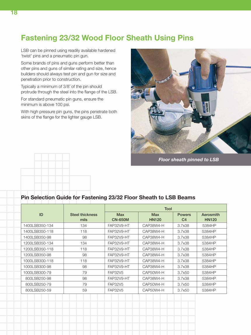
LSB can be pinned using readily available hardened‘twist’ pins and a pneumatic pin gun.
Some brands of pins and guns perform better thanother pins and guns of similar rating and size, hencebuilders should always test pin and gun for size andpenetration prior to construction.
Typically a minimum of 3/8˝ of the pin shouldprotrude through the steel into the flange of the LSB.
For standard pneumatic pin guns, ensure theminimum is above 100 psi.
With high pressure pin guns, the pins penetrate bothskins of the flange for the lighter gauge LSB.
Fastening 23/32 Wood Floor Sheath Using Pins
Tool
ID Steel thickness Max Max Powers Aerosmithmils CN-650M HN120 C4 HN120
1400LSB350-134 134 FAP32V9-HT CAP38W4-H 3.7x38 5384HP
1400LSB350-118 118 FAP32V9-HT CAP38W4-H 3.7x38 5384HP
1400LSB350-98 98 FAP32V9-HT CAP38W4-H 3.7x38 5384HP
1200LSB350-134 134 FAP32V9-HT CAP38W4-H 3.7x38 5384HP
1200LSB350-118 118 FAP32V9-HT CAP38W4-H 3.7x38 5384HP
1200LSB350-98 98 FAP32V9-HT CAP38W4-H 3.7x38 5384HP
1000LSB300-118 118 FAP32V9-HT CAP38W4-H 3.7x38 5384HP
1000LSB300-98 98 FAP32V9-HT CAP38W4-H 3.7x38 5384HP
1000LSB300-79 79 FAP32V5 CAP50W4-H 3.7x50 5384HP
800LSB250-98 98 FAP32V9-HT CAP38W4-H 3.7x38 5384HP
800LSB250-79 79 FAP32V5 CAP50W4-H 3.7x50 5384HP
800LSB250-59 59 FAP32V5 CAP50W4-H 3.7x50 5384HP
Pin Selection Guide for Fastening 23/32 Floor Sheath to LSB Beams
Floor sheath pinned to LSB

19
Welding LSB®
Manual Metal Arc Welding(MMAW)–“Stick”
• 0.10˝ diameter electrodes are preferred.
• Use low power setting (60 to 70 amps).
• AWS A5.1: E6013 electrodes will give a smooth weld with no visible porosity. Suitable electrodes include Lincoln Fleetweld 37 and ESAB Sureweld 6013-LV; confirm suitability with the electrode manufacturer.
• Excessive heat should be avoided. Do not over-weld.
• Keep arc length short to avoid burn-through and undercut.
Welding may cause discoloration of the LSB coating.
Excessive welding may distort the LSB.
LSB can usually be welded using the sameconsumables commonly used for welding 50 ksi steel.
If the weld will be exposed to moisture, touch upthe weld area with cold galvanized paint.
Quick TipsSpeed of welding should be a little slower thanfor uncoated steel of the same thickness.
Use an anti-spatter spray prior to welding toassist cleaning up. Make sure the spatter releaseis not sprayed into the welded joint.
All welds should have any slag removed bychipping followed by wire brushing to clean theadjacent area.
LSB can be readily welded using appropriate arcwelding processes. Welding consumables suitable for LSB are:
• Manual Metal Arc Welding Stick Electrodes(E60XX electrodes).
• Gas Metal Arc Welding (ER70S-X wire consumables).
• Flux Cored Arc Welding (E71T-1M-H8 wire consumables).
• Limit weld size to LSB thickness
Gas Metal Arc Welding(GMAW)–“Mig”
• 0.035˝ diameter wire is recommended.
• Wire feed speed of approximately 180 ipm at 90 Amps and 15V.
• A hand piece lead of 20° with the wire pointing in the direction of travel will reduce porosity and nozzle clogging.
• Argon with 15 to 20% CO2 reduces spatter and improves weld appearance.
• AWS A5.18: ER70S-4 welding wires are recommended. Lincoln Murematic S4+, Lincoln Super Arc® L-54 and ESAB Spoolarc 85 are suitable wires; confirm the feed speed, amperage, voltage, and gas mix with the wire manufacturer.
Welded LSB Fascia
Welding LSB

20
Painting Guidelines
For aesthetic applications or more corrosive environments, LSB can be painted. For best resultsthe surface should be prepared with a galvanizedmetal primer.
When applying a painted finish to LSB:
• Degrease the galvanized coat with methylated spirits. Wipe the beam clean after solvent washing.
• Prepare the surface with a galvanized metal primer.
• Carefully read the Paint Manufacturer’s “Instructionsfor Use”. Check to ensure the paint is suitable for use on galvanized steel and is suitable for the exposure category.
• Paint the LSB in accordance with the Paint Manufacturer’s recommendations and instructions.
Painting Conditions
Painting should be carried out on warm, dry dayswithout heavy frost or dews.
In hot weather, avoid painting surfaces exposed todirect sunlight as this may result in patchiness orblistering of the paint.
Painting LSB®
Painted LSB on exposed framing
Painted LSB with wood infill
Painted LSB fascia

21
Using LSB® Back-to-Back
LSB Back-to-Back for Added Strength
LSB is generally used as a single beam or girder. Theymay also be used in the back-to-back configuration.Reasons for using LSB back-to-back include:
• Need for greater carrying capacity or greater span than from a single LSB
• In remodeling and other applications that need to use shallowest beam
• Need for beams of lightest weight to facilitate movement on-site
Assembling LSB Back-to-Back
When using LSB back-to-back, they should befastened together:
• Using two 1/2˝ bolts at six foot intervals
...or
• Using #12 Teks 4 self-taping screws, staggeredat one foot intervals, and two screws at the ends evenly spaced

Option 1: Half LSB Section
• Section of LSB of same flange depth, cut in half longitudinally, and cut to length to fit tight between the LSB flanges.
• 3–#12-24 x 1-1/2˝ hex head Teks® screws with #5 drill point (Buildex part number 1070000)
Using StiffenersLSB beams often require a web stiffener at supportsand at point load locations. Stiffeners should be usedunless a design professional determines they are notrequired. For concentrated point loads exceeding10,000 pounds consult a design professional.
The stiffener can be a half section of LSB, a pair ofwood studs, or a steel stud. The stiffener should fitsnugly between the LSB beam flanges.
Option 3: 350S162-54 Steel Stud
• 350S162-54 steel stud, cut to length to fit tight between the LSB flanges. Web of steel stud is against LSB beam web.
• 4–#12-14 x 1-1/4˝ hex head Teks® screws with #2 drill point (Buildex® part number 1120000)
Option 2: 2-2 x 4 Wood Studs
• 2–2 x 4˝ SPF #2 wood studs, cut to length to fit tight between the LSB flanges. 2˝ nominal face of wood studs is against LSB beam web.
• 3–#12 gauge wood screws each stud. Pre-drill 7/32˝ holes for screws through LSB web.
22

ConnectionsThis document does not express warranties in regard toconnections. Design and structural loads must be determined byan appropriately qualified design professional. Connectorsuitability must be determined by the connector manufacturer.
Material Compatibility, Storage, and HandlingFor information on material compatibility, storage, and handlingcontact LiteSteel Technologies America LLC.
Contact Us for Technical SupportFor further information, technical support or commentson LSB call 877-285-2607.E-mail: [email protected]
LiteSteel Technologies America, LLC (“LiteSteel”) endeavors to publish accurate technical specifications and reliableproduct performance data. However, the technical data, product specifications, and product performance data providedby LiteSteel in this publication and elsewhere are not a substitute for the professional expertise, recommendations andjudgment of a certified engineering professional after consideration of important factors like specific project objectives,anticipated structural demands, environmental and climate conditions, and governmental code requirements. Always seek the advice of a Professional Engineer duly registered in your jurisdiction.
NO WARRANTY SHALL BE IMPLIED BY ANY PART OR THE WHOLE OF THIS INSTALL GUIDE. EXCEPT ASEXPRESSED BY LITESTEEL IN A SEPARATE WRITTEN STATEMENT CLEARLY INDICATED TO CONSTITUTE ANEXPRESS WARRANTY, THERE ARE NO WARRANTIES, EXPRESS OR IMPLIED, INCLUDING BUT NOT LIMITED TOWARRANTIES OF MERCHANTABILITY OR FITNESS FOR A PARTICULAR PURPOSE. In any jurisdiction that does notpermit the exclusion of implied warranties or limitations on applicable statutory rights of the consumer or otherwise limitsthe effectiveness of these warranty exclusions, LiteSteel’s liability is limited to the greatest extent permitted by law. Thepurchaser of LiteSteel’s products shall be solely responsible for the selection, installation, use, efficiency, and suitability ofthe products purchased, and LiteSteel shall have no liability therefore.
LiteSteel Technologies America LLCP.O. Box 577Troutville, VA 24175540-992-1600 • FAX: 540-992-5998
© LiteSteel Technologies America, LLC, 2010 Printed in USALiteSteel beam is a trademark and LSB is a registered trademark and areused under license by LiteSteel Technologies America, LLC.LiteSteel Technologies America LLC is a OneSteel Group Company.Buildex® and Teks® are registered trademarks of Illinois Tool Works Inc.Lincoln Super Arc® is a registered trademark of Lincoln Electric CompanyLSBIG 0210
507 LSB cover:Layout 1 2/12/10 1:58 PM Page 1