installermanual - nibe4xlfnjxlgh 1dyljdwlrq 2nexwwrq frqilup vhohfw %dfnexwwrq edfn xqgr h[lw...
TRANSCRIPT

Installer manual
LEK
NIBE™ F1245PCGround source heat pump
IHB GB 1343-2231810

A detailed explanation of the button functions can be found on page 34.
How to scroll through menus and make different settings is described on page 36.
The mode for setting the indoor temperature is reached, when in the start mode in the main menu, by pressingthe OK button twice. Read more about the settings on page 38.
To temporarily increase the amount of hot water, first turn the control knob to mark menu 2 (water droplet) andthen press the OK button twice. Read more about the settings on page 46.
In event of disturbances in comfortIf a disturbance in comfort of any type occurs there are some measures that can be taken before you need tocontact your installer. See page 68 for instructions.
Table of Contents1 Important information 2
Safety information 2
2 Delivery and handling 5Transport 5
Assembly 5
Supplied components 6
Removing the covers 6
Removing parts of the insulation 7
3 The heat pump design 8General 8
Electrical cabinets 10
Cooling section 12
4 Pipe connections 13General 13
Dimensions and pipe connections 14
Brine side 14
Heating medium side 15
Hot water heater 15
Docking alternatives 15
5 Electrical connections 18General 18
Connections 20
Settings 22
Optional connections 24
Connecting accessories 27
6 Commissioning and adjusting 28
Preparations 28
Filling and venting 28
Start guide 29
Post adjustment and venting 30
7 Control - Introduction 34Display unit 34
Menu system 35
8 Control - Menus 38Menu 1 - INDOOR CLIMATE 38
Menu 2 - HOT WATER 46
Menu 3 - INFO 48
Menu 4 - HEAT PUMP 49
Menu 5 - SERVICE 54
9 Service 62Service actions 62
10 Disturbances in comfort 68Info-menu 68
Manage alarm 68
Troubleshooting 68
11 Accessories 70
12 Technical data 72Dimensions and setting-out coordinates 72
Technical specifications 73
Item register 77
1Table of Contents |NIBE™ F1245PC

Safety informationThis manual describes installation and service proced-ures for implementation by specialists.
This appliance can be used by childrenaged from 8 years and above and per-sons with reduced physical, sensory ormental capabilities or lack of experienceand knowledge if they have been givensupervision or instruction concerninguse of the appliance in a safe way andunderstand the hazards involved. Chil-dren shall not play with the appliance.Cleaning and user maintenance shallnot be made by children without super-vision.Rights to make any design or technicalmodifications are reserved.©NIBE 2013.
Symbols
NOTE
This symbol indicates danger to machine orperson.
Caution
This symbol indicates important informationabout what you should observe when main-taining your installation.
TIP
This symbol indicates tips on how to facilitateusing the product.
MarkingThe CE marking means that NIBE ensures that theproduct meets all regulations that are placed on itbased on relevant EU directives. The CE mark is obligat-ory for most products sold in the EU, regardless wherethey are made.
Serial numberThe serial number can be found at the bottom right ofthe front cover and in the info menu (menu 3.1).
Caution
Always give the product's serial number (14digits) when reporting a fault.
Country specific information
Installer manual
This installer manual must be left with the customer.
NIBE™ F1245PCChapter 1 | Important information2
1 Important information

Inspection of the installationCurrent regulations require the heating installation to be inspected before it is commissioned. The inspection mustbe carried out by a suitably qualified person. Fill in the page for information about installation data in the Usermanual.
DateSignatureNotesDescription✔
Brine (page 14)
System flushed
System vented
Antifreeze
Level/Expansion vessel
Particle filter
Safety valve
Shut off valves
Circulation pump setting
Heating medium (page 15)
System flushed
System vented
Expansion vessel
Particle filter
Safety valve
Shut off valves
Circulation pump setting
Electricity (page 18)
Fuses heat pump
Fuses property
Outside sensor
Room sensor
Current sensor
Safety breaker
Earth circuit-breaker
Setting of emergency mode thermostat
Miscellaneous
Guarantee submitted
3Chapter 1 | Important informationNIBE™ F1245PC
Contact informationKNV Energietechnik GmbH, Gahberggasse 11, 4861 SchörflingAT
Tel: +43 (0)7662 8963-0 Fax: +43 (0)7662 8963-44 E-mail: [email protected] www.knv.atNIBE Wärmetechnik AG, Winterthurerstrasse 710, CH-8247 FlurlingenCH
Tel: (52) 647 00 30 Fax: (52) 647 00 31 E-mail: [email protected] www.nibe.chDruzstevni zavody Drazice s.r.o, Drazice 69, CZ - 294 71 Benatky nad JizerouCZ
Tel: +420 326 373 801 Fax: +420 326 373 803 E-mail: [email protected] www.nibe.czNIBE Systemtechnik GmbH, Am Reiherpfahl 3, 29223 CelleDE
Tel: 05141/7546-0 Fax: 05141/7546-99 E-mail: [email protected] www.nibe.deVølund Varmeteknik A/S, Member of the Nibe Group, Brogårdsvej 7, 6920 VidebækDK
Tel: 97 17 20 33 Fax: 97 17 29 33 E-mail: [email protected] www.volundvt.dkNIBE Energy Systems OY, Juurakkotie 3, 01510 VantaaFI
Puh: 09-274 697 0 Fax: 09-274 697 40 E-mail: [email protected] www.nibe.fiAIT France, 10 rue des Moines, 67000 HaguenauFR
Tel : 03 88 06 24 10 Fax : 03 88 06 90 15 E-mail: [email protected] www.nibe.frNIBE Energy Systems Ltd, 3C Broom Business Park, Bridge Way, Chesterfield S41 9QGGB
Tel: 0845 095 1200 Fax: 0845 095 1201 E-mail: [email protected] www.nibe.co.ukNIBE Energietechniek B.V., Postbus 2, NL-4797 ZG WILLEMSTAD (NB)NL
Tel: 0168 477722 Fax: 0168 476998 E-mail: [email protected] www.nibenl.nlABK AS, Brobekkveien 80, 0582 Oslo, Postadresse: Postboks 64 Vollebekk, 0516 OsloNO
Tel. sentralbord: +47 23 17 05 20 E-mail: [email protected] www.nibeenergysystems.noNIBE-BIAWAR Sp. z o. o. Aleja Jana Pawła II 57, 15-703 BIAŁYSTOKPL
Tel: 085 662 84 90 Fax: 085 662 84 14 E-mail: [email protected] www.biawar.com.pl© "EVAN" 17, per. Boynovskiy, Nizhny NovgorodRU
Tel./fax +7 831 419 57 06 E-mail: [email protected] www.nibe-evan.ruNIBE AB Sweden, Box 14, Hannabadsvägen 5, SE-285 21 MarkarydSE
Tel: +46-(0)433-73 000 Fax: +46-(0)433-73 190 E-mail: [email protected] www.nibe.se
For countries not mention in this list, please contact Nibe Sweden or check www.nibe.eu for more information.
NIBE™ F1245PCChapter 1 | Important information4
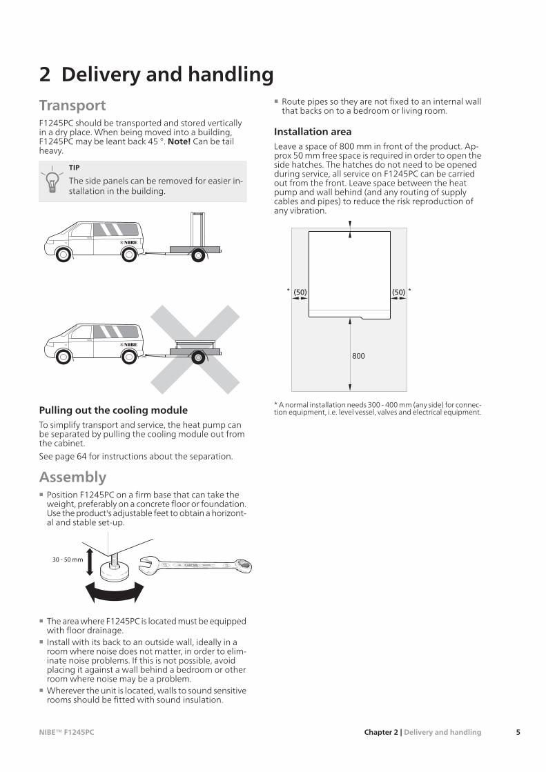
TransportF1245PC should be transported and stored verticallyin a dry place. When being moved into a building,F1245PC may be leant back 45 °. Note! Can be tailheavy.
TIP
The side panels can be removed for easier in-stallation in the building.
R
0
R0
Pulling out the cooling moduleTo simplify transport and service, the heat pump canbe separated by pulling the cooling module out fromthe cabinet.
See page 64 for instructions about the separation.
AssemblyPosition F1245PC on a firm base that can take theweight, preferably on a concrete floor or foundation.Use the product's adjustable feet to obtain a horizont-al and stable set-up.
30 - 50 mm
The area where F1245PC is located must be equippedwith floor drainage.Install with its back to an outside wall, ideally in aroom where noise does not matter, in order to elim-inate noise problems. If this is not possible, avoidplacing it against a wall behind a bedroom or otherroom where noise may be a problem.Wherever the unit is located, walls to sound sensitiverooms should be fitted with sound insulation.
Route pipes so they are not fixed to an internal wallthat backs on to a bedroom or living room.
Installation areaLeave a space of 800 mm in front of the product. Ap-prox 50 mm free space is required in order to open theside hatches. The hatches do not need to be openedduring service, all service on F1245PC can be carriedout from the front. Leave space between the heatpump and wall behind (and any routing of supplycables and pipes) to reduce the risk reproduction ofany vibration.
(50) (50)
* A normal installation needs 300 - 400 mm (any side) for connec-tion equipment, i.e. level vessel, valves and electrical equipment.
5Chapter 2 | Delivery and handlingNIBE™ F1245PC
2 Delivery and handling

Supplied componentsLEK
LEK
LEK
Room sensorCurrent sensor (not1x230V)
Outside sensor
LEK
LEK
O-ringsSafety valve(0.3 MPa) (3 bar)
Level vessel
LEK
LE
K
MAGNA
Made in Germany
Min.
I1/1
1(A)
(W)
Max.
Min.
P
Max.Min.
Max.
P/N 96917292
PC 0931NIB
1x230-240V 50/60HzTF110
IPX4
1.2518510
0,09 1,0MPa
-10°C
GE025-100 180
Installation kit forexternal brine
pump (for 10 kWonly).
External brinepump (for 10 kW
only).
LocationThe kit of supplied items is placed in packaging on topof the heat pump.
Removing the coversFront cover
1
2
LE
K
LE
K
1. Remove the screws from the lower edge of thefront cover.
2. Lift the cover out at the bottom edge and up.
Side coversL
EK
LE
K
LE
K
The side covers can be removed to facilitate the install-ation.1. Remove the screws from the upper and lower
edges.2. Twist the cover slightly outward.3. Move the cover backwards and slightly to the side.4. Pull the cover to one side.5. Pull the cover forwards.
NIBE™ F1245PCChapter 2 | Delivery and handling6

Removing parts of the insula-tionParts of the insulation can be removed to facilitate theinstallation.
Insulation, top1. Disconnect the cable from the motor and remove
the motor from the shuttle valve as illustrated.
LEK
LEK
A
B
LEK
2. Grip the handle and pull straight out as illustrated.
LEK
Insulation, immersion heater
NOTE
Electrical installation and service must be car-ried out under the supervision of a qualifiedelectrician. Electrical installation and wiringmust be carried out in accordance with thestipulations in force.
1. Remove the cover for the junction box accordingto the description on page 19.
2. Grip the handle and pull the insulation carefullytowards you as illustrated.
LEK
7Chapter 2 | Delivery and handlingNIBE™ F1245PC

General
F1245
BT7
QN10
BT2
EB1
UB1
QM34
XL1
XL6 XL7
XL4 XL3 XL2
FR1
PF1
PF3BT6
UB2
QM32
QM33
PF2
QM22
UB3
AA4
W130
QM31
AA4-XJ3
AA4-XJ3
SF1
View from above
View from behind
NIBE™ F1245PCChapter 3 | The heat pump design8
3 The heat pump design

Pipe connectionsConnection, heating medium flowXL 1Connection, heating medium returnXL 2Connection, cold waterXL 3Connection, hot waterXL 4Connection, HWCXL 5Connection, brine inXL 6Connection, brine outXL 7
HVAC componentsVenting, coilQM 22Shut-off valve, heating medium flowQM 31Shut off valve, heating medium returnQM 32Shut off valve, brine outQM 33Shut-off valve, brine inQM 34Shuttle valve, climate system/water heaterQN 10
Sensors etc.Flow meter (only for Germany, Switzerland andAustria)
BF 1
Outside sensorBT 1Temperature sensors, heating medium flowBT 2Temperature sensor, hot water chargingBT 6Temperature sensor, hot water topBT 7
Electrical componentsDisplay unitAA 4
AA4-XJ3 USB socket
AA4-XJ4 Service outlet (No function)Immersion heaterEB 1Sacrificial anode*FR 1SwitchSF 1Network cable for NIBE UplinkTMW130
* Only heat pump with enamelled vessel.
MiscellaneousRating platePF 1Type plate, cooling sectionPF 2Serial number platePF 3Cable gland, incoming electricityUB 1Cable glandUB 2Cable gland, rear side, sensorUB 3
Designations in component locations according tostandard IEC 81346-1 and 81346-2.
9Chapter 3 | The heat pump designNIBE™ F1245PC

Electrical cabinets
F1245
Electrical componentsImmersion heater cardAA 1Base cardAA 2Input circuit boardAA 3Extra relay circuit boardAA 7Sacrificial anode card*AA 8Miniature circuit-breakerFA 1Motor cut-out**FB 1
Temperature limiter/Emergency mode thermo-stat
FD 1
* Only heat pump with enamelled vessel.
** 5 kW has auxiliary switch for motor cut-out.
Designations in component locations according tostandard IEC 81346-1 and 81346-2.
NIBE™ F1245PCChapter 3 | The heat pump design10

1x230 V 5 kW
3x400 V 5 kW
3x400 V 6-10 kW
Electrical componentsSoft-start cardAA 10CapacitorCA 1Motor cut-out**FB 1Soft-starterQA 30Terminal blockX 301Terminal blockX 302
** 5 kW has auxiliary switch for motor cut-out.
Designations in component locations according tostandard IEC 81346-1 and 81346-2.
11Chapter 3 | The heat pump designNIBE™ F1245PC

Cooling section
LEK
LEK
1x230V 5 kW3x400V 5 kWEP2
BT14
BT17
EP1
BP2
BT15
BP1
GQ10
HS1
XL21
QN1EB10 XL20
Pipe connectionsService connection, high pressureXL 20Service connection, low pressureXL 21
HVAC componentsCirculation pumpGP 1Brine pumpGP 2Drainage, climate systemQM 1Draining, brine sideQM 2
Sensors etc.High pressure pressostatBP 1Low pressure pressostatBP 2Temperature sensors, heating medium returnBT 3Temperature sensor, brine inBT 10Temperature sensor, brine outBT 11Temperature sensor, condenser supply lineBT 12Temperature sensor, hot gasBT 14Temperature sensor, fluid pipeBT 15Temperature sensor, suction gasBT 17
Electrical componentsJoint cardAA 100Compressor heaterEB 10
Cooling componentsEvaporatorEP 1CondenserEP 2Heat exchanger, coolingEP 6CompressorGQ 10Drying filterHS 1Expansion valveQN 1Mixing valve, coolingQN 18
Designations in component locations according tostandard IEC 81346-1 and 81346-2.
NIBE™ F1245PCChapter 3 | The heat pump design12

GeneralPipe installation must be carried out in accordance withcurrent norms and directives. F1245PC can operatewith a return temperature of up to 58 °C and an outgo-ing temperature from the heat pump of 70 (65 °C withonly the compressor).
F1245PC is not equipped with external shut off valves;these must be installed to facilitate any future servicing.
Caution
Any high points in the climate system, mustbe equipped with air vents.
NOTE
The pipe system needs to be flushed out be-fore the heat pump is connected so that debriscannot damage component parts.
NOTE
The climate system must be adjusted for bothheating and cooling operation.
Symbol key
MeaningSymbol
Venting valve
Shut-off valve
Non-return valve
Shunt / shuttle valve
Safety valve
Trim valve
Temperature sensor
Level vessel
Expansion vessel
Pressure gaugeP
Circulation pump
Particle filterAuxiliary relay
Flow meter (only for Germany, Switzerland andAustria)Compressor
Heat exchanger
System diagramF1245PC consists of a heat pump, water heater, elec-trical module, circulation pumps and a control system.F1245PC is connected to the brine and heating mediumcircuits.
In the heat pump evaporator, the brine (water mixedwith anti-freeze, glycol or ethanol) releases its energyto the refrigerant, which is vaporised in order to becompressed in the compressor. The refrigerant, ofwhich the temperature has now been raised, is passedto the condenser where it gives off its energy to theheating medium circuit and, if necessary, to the waterheater. If there is a greater need for heating/hot waterthan the compressor can provide there is an integratedimmersion heater.
The brine can also be circulated via a mixing valve to aheat exchanger. There the brine cools the heating sys-tem's water so that comfort cooling can be maintainedduring the hotter periods of the year.
Connection, heating medium flowXL 1Connection, heating medium returnXL 2Connection, cold waterXL 3Connection, hot waterXL 4Connection, brine inXL 6Connection, brine outXL 7
13Chapter 4 | Pipe connectionsNIBE™ F1245PC
4 Pipe connections

Dimensions and pipe connec-tions
62
0
600
560 440
70
17
75
65
0*
25
-50
25
50
130
210
390
470
525
65
0*
Pipe dimensions
5-10(kW)Connection
28(mm)(XL6)/(XL7) Brine in/out ext Ø
22(mm)(XL1)/(XL2) Heating mediumflow/return ext Ø
22(mm)(XL3)/(XL4) Cold/hot water Ø
Brine sideCollector
Rock heat, recom-mended active
drilling depth (m)
Surface soil heat,recommended col-lector length (m)
Type
70-90200-3005 kW90-110250-4006 kW
120-145325-2x2508 kW150-180400-2x30010 kW
Applies to PEM hose 40x2.4 PN 6.3.
These are rough example values. At installation thecorrect calculations must be made according to localconditions.
Caution
The length of the collector hose varies depend-ing on the rock/soil conditions, climate zoneand on the climate system (radiators or under-floor heating).
Max length per coil for the collector should not exceed400 m.
In those cases where it is necessary to have severalcollectors, these should be connected in parallel withthe possibility for adjusting the flow of the relevantcoil.
For surface soil heat, the hose should be buried at adepth determined by local conditions and the distancebetween the hoses should be at least 1 metre.
For several bore holes, the distance between the holesmust be determined according to local conditions.
Ensure the collector hose rises constantly towards theheat pump to avoid air pockets. If this is not possible,airvents should be used.
As the temperature of brine system can fall below 0 °Cit must be protected against freezing down to -15 °C.1 litre of ready mixed brine per meter of collector hose(applies when using PEM-hose 40x 2.4 PN 6.3) is usedas a guide value when making the volume calculation.
Side connectionIt is possible to angle the brine connections, for connec-tion to the side instead of top connection.
To angle out a connection:1. Disconnect the pipe at the top connection.2. Angle the pipe in the desired direction.3. If necessary, cut the pipe to the desired length.
Connecting the brine sideInsulate all indoor brine pipes against condensation.The level vessel must be installed as the highest pointin the brine system on the incoming pipe before thebrine pump (Alt. 1).
* Can be angled for side connection.
NIBE™ F1245PCChapter 4 | Pipe connections14

If the level vessel cannot be placed at the highestpoint an expansion vessel must be used (Alt. 2).
NOTE
Note that condensation may drip from thelevel vessel. Position the vessel so that this doesnot harm other equipment.
Details of the antifreeze used must be shown on thelevel vessel.Install the supplied safety valve under the level vesselas illustrated. The entire length of the overflow waterpipe from the safety valves must be inclined to pre-vent water pockets and must also be frost proof.Install shut off valves as close to the heat pump aspossible.Fit the supplied particle filter on the incoming pipe.
In the case of connection to an open groundwatersystem, an intermediate frost-protected circuit mustbe provided, because of the risk of dirt and freezing inthe evaporator. This requires an extra heat exchanger.
P
Connecting external brine pump (10 kWonly)Install the brine pump at the connection for incomingbrine (XL6) between F1245PC and the shutoff valve(see illustration).
NOTE
Insulate the brine pump against condensation.
Heating medium sideConnecting the climate systemA climate system is a system that regulates indoorcomfort with the help of the control system in F1245PCand for example radiators, underfloor heating/cooling,fan convectors etc.
Install all required safety devices, shut-off valves (asclose to the heat pump as possible), and suppliedparticle filter.The safety valve must have a maximum 0.25 MPa (2.5bar) opening pressure and be installed on the heatingmedium return as illustrated. The entire length ofthe overflow water pipe from the safety valves must
be inclined to prevent water pockets and must alsobe frost proof.When connecting to a system with thermostats onall radiators, a relief valve must be fitted, or some ofthe thermostats must be removed to ensure sufficientflow.
P
Hot water heaterConnecting the hot water heater
The hot water heater in the heat pump must besupplied with necessary set of valves.The mixing valve must be installed if the setting ischanged so that the temperature can exceed 60 °C.The setting for hot water is made in menu 5.1.1.The safety valve must have a maximum 1.0 MPa (10.0bar) opening pressure and be installed on the incom-ing domestic water line as illustrated. The entirelength of the overflow water pipe from the safetyvalves must be inclined to prevent water pockets andmust also be frost proof.
Docking alternativesF1245PC can be connected in several different ways,some of which are shown below.
Further option information is available at www.nibe.euand in the respective assembly instructions for the ac-cessories used. See page 70 for a list of the accessoriesthat can be used with F1245PC.
15Chapter 4 | Pipe connectionsNIBE™ F1245PC

Extra electric hot water heaterThe heat pump should be supplemented with an elec-tric water heater, for example NIBE COMPACT, if awhirlpool or other significant consumer of hot wateris installed.
The valve connection on COMPACT can be separated.The mixing valve remains on COMPACT and the re-maining valve connector can be used for incomingcold water in F1245PC.
VV
KV
Buffer vesselIf the climate system volume is too small for the heatpump output, the radiator system can be supplementedwith a buffer vessel, for example NIBE UKV.
UKV
P
Ventilation recoveryThe installation can be supplemented with the exhaustair module FLM to provide ventilation recovery.
Pipes and other cold surfaces must be insulated withdiffusion-proof material to prevent condensation.The brine system must be supplied with a pressureexpansion vessel (CM3). If there is a level vessel (CM2)this should be replaced.
Frånluft Ø 160
Avluft Ø 160
P
Under floor heating systemsThe external circulation pump is dimensioned for theunder floor heating system’s demand.
If the climate system volume is too small for the heatpump output, the underfloor heating system can besupplemented with a buffer vessel, for example NIBEUKV.
UKV
P
NIBE™ F1245PCChapter 4 | Pipe connections16

Two or more climate systemsWhen more than one climate system, with a lowertemperature, is to be heated up, the following connec-tion can be used. The shunt valve lowers the temperat-ure to, for example, the under floor heating system.
The ECS 40/ECS 41 accessory is required for this con-nection.
Ground water systemAn intermediate heat exchanger is used to protect theheat pump's exchanger from dirt. The water is releasedinto a buried filtration unit or a drilled well. See page26 for more information about connecting a groundwater pump.
If this docking alternative is used, "min. brine out" inmenu 5.1.7 "br pmp al set." must be changed to asuitable value to prevent freezing in the heat ex-changer.
PoolCharging of the pool is controlled by the pool sensor.In the case of low pool temperatures, the shuttle valvereverses direction and opens towards the pool ex-changer. The POOL 40 accessory is required for thisconnection.
Pool
17Chapter 4 | Pipe connectionsNIBE™ F1245PC

GeneralAll electrical equipment, except the outdoor sensors,room sensors and the current sensors are ready connec-ted at the factory.
Disconnect the heat pump before insulation testingthe house wiring.F1245PC is not reconnectable between 1-phase and3-phase.If the building is equipped with an earth-faultbreaker, F1245PC should be equipped with a separ-ate one.If a miniature circuit breaker is used this should haveat least motor characteristic “C”. See page 73 for fusesize.For wiring diagrams for the heat pump, see separateinstallation handbook for wiring diagrams.Communication and sensor cables to external con-nections must not be laid close to high current cables.The minimum area of communication and sensorcables to external connections must be 0.5 mm² upto 50 m, for example EKKX or LiYY or equivalent.When cable routing in F1245PC, cable grommets(e.g. UB1-UB3, marked in image) must be used. InUB1-UB3 the cables are inserted through the heatpump from the back to the front.
NOTE
The switch (SF1) must not be moved to "" or" " until the boiler has been filled with water.Otherwise the temperature limiter, thermostat,compressor and the immersion heater can bedamaged.
NOTE
Electrical installation and service must be car-ried out under the supervision of a qualifiedelectrician. Cut the current with the circuitbreaker before carrying out any servicing.Electrical installation and wiring must be car-ried out in accordance with the stipulations inforce.
F1245
FD1
FA1
FB1
FD1-SF2
UB2
UB1
UB3
Miniature circuit-breakerThe heat pump operating circuit and a large proportionof its internal components are internally fused by aminiature circuit breaker (FA1).
Temperature limiterThe temperature limiter (FD1) cuts the current supplyto the electrical addition if the temperature risesbetween 90 and 100°C and can be manually reset.
Resetting
The temperature limiter (FD1) is accessible behind thefront cover. Reset the temperature limiter by pressingthe button (FD1-SF2) using a small screwdriver.
Motor cut-outMotor protection breaker (FB1) cuts the power to thecompressor if the current is too high.
Resetting
The motor protection breaker (FB1) is accessible behindthe front cover. The breaker is reset by twisting thecontrol knob to horizontal position.
Caution
Check the miniature circuit-breaker, temperat-ure limiter and motor protection breaker. Theymay have tripped during transportation.
NIBE™ F1245PCChapter 5 | Electrical connections18
5 Electrical connections

Accessibility, electrical connectionThe plastic cap of the electrical boxes is opened usinga screwdriver.
NOTE
The cover for the input card is opened withouta tool.
Removing the cover, input circuit board
LEK
1
2
1. Push the catch down.2. Angle out the cover and remove it.
Removing the cover, immersionheater circuit board
LEK
1
2
A
B
1. Insert the screwdriver (A) and pry the catch care-fully downwards (B).
2. Angle out the cover and remove it.
Removing the cover, base board
Caution
To remove the cover for the base board, thecover for the input circuit board must first beremoved.
LEK
LEK
1
A
B
2
1. Disconnect the switches using a screwdriver.2. Insert the screwdriver (A) and pry the catch care-
fully downwards (B).3. Angle out the cover and remove it.
Cable lockUse a suitable tool to release/lock cables in the heatpump terminal blocks.
2
1
2
3
LEK
3
4
1
2
19Chapter 5 | Electrical connectionsNIBE™ F1245PC
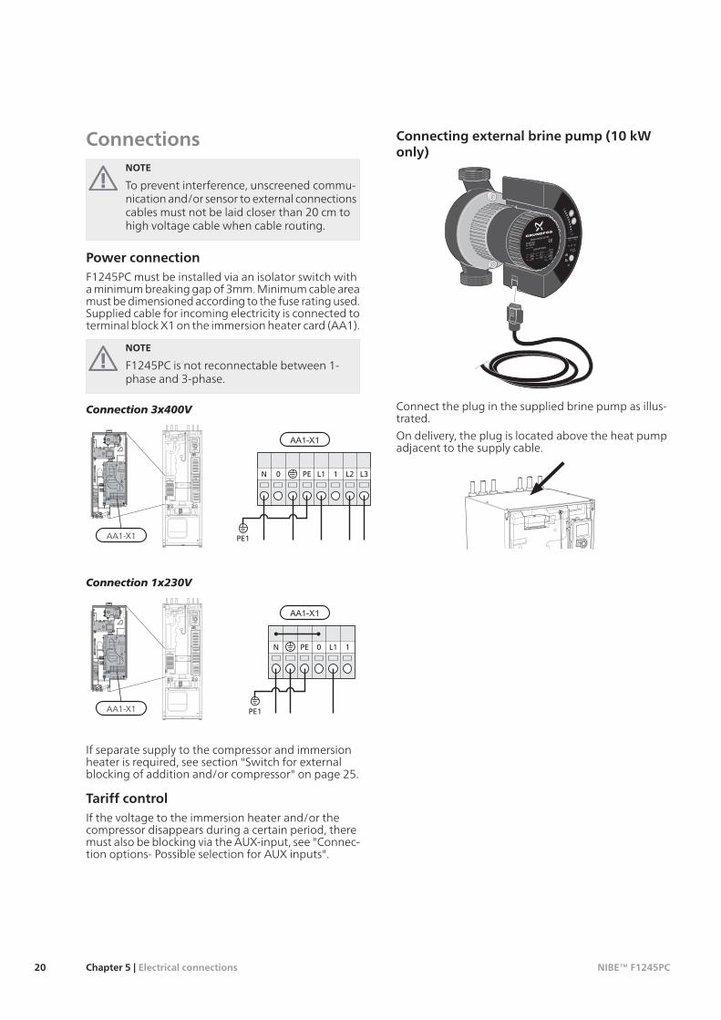
ConnectionsNOTE
To prevent interference, unscreened commu-nication and/or sensor to external connectionscables must not be laid closer than 20 cm tohigh voltage cable when cable routing.
Power connectionF1245PC must be installed via an isolator switch witha minimum breaking gap of 3mm. Minimum cable areamust be dimensioned according to the fuse rating used.Supplied cable for incoming electricity is connected toterminal block X1 on the immersion heater card (AA1).
NOTE
F1245PC is not reconnectable between 1-phase and 3-phase.
Connection 3x400V
PE1
L1 1 L2 L3PE0N
F1245
AA1-X1
Connection 1x230V
PE1
0 L1 1PEN
F1245
AA1-X1
If separate supply to the compressor and immersionheater is required, see section "Switch for externalblocking of addition and/or compressor" on page 25.
Tariff controlIf the voltage to the immersion heater and/or thecompressor disappears during a certain period, theremust also be blocking via the AUX-input, see "Connec-tion options- Possible selection for AUX inputs".
Connecting external brine pump (10 kWonly)
LE
K
MAGNA
Made in Germany
Min.
I1/1
1(A)
(W)
Max.
Min.
P
Max.Min.
Max.
P/N 96917292
PC 0931NIB
1x230-240V 50/60HzTF110
IPX4
1.2518510
0,09 1,0MPa
-10°C
GE025-100 180
Connect the plug in the supplied brine pump as illus-trated.
On delivery, the plug is located above the heat pumpadjacent to the supply cable.
NIBE™ F1245PCChapter 5 | Electrical connections20

Connecting external operating voltage forthe control system
NOTE
Only applies to power connection of 3x400V.
NOTE
Mark up any junction boxes with warnings forexternal voltage.
If you wish to connect external operating voltage forthe control system to F1245PC on the immersionheater circuit board (AA1) the edge connector atAA1:X2 must be moved toAA1:X9 (as illustrated).
When connecting external operating voltage for thecontrol system with separate earth-fault breaker, dis-connect the blue cable from terminal block X7:24 onthe immersion heater circuit board (AA1) and connectin the enclosed top clamp together with the incomingoperating zero. Connect a blue cable (min 0.75 mm2)between the top clamp and X11:N on the immersionheater circuit board (as illustrated).
Operating voltage (1x230V+N+PE) is connected toAA1:X11 (as illustrated).
1 2
3
4
5
6
ON
L1 1 L2 L3PE
PE
0N
NL
* Only with separate earth-fault breaker.
Outside sensorInstall the outside temperature sensor (BT1) in theshade on a wall facing north or north-west, so it is un-affected by the morning sun.
Connect the sensor to terminal block X6:1 and X6:2 onthe input card (AA3). Use a twin core cable of at least0.5 mm² cable area.
If a conduit is used it must be sealed to prevent con-densation in the sensor capsule.
123456
F1245
AA3-X6
Temperature sensor, external flow lineIf temperature sensor, external flow line (BT25) needsto be used, connect it to terminal block X6:5 and X6:6on the input card (AA3). Use a 2 core cable of at least0.5 mm² cable area.
123456789
F1245
F1245
AA3-X6
21Chapter 5 | Electrical connectionsNIBE™ F1245PC

Room sensorF1245PC is delivered with a room sensor supplied(BT50). The room temperature sensor has up to threefunctions:1. Show current room temperature in F1245PC's dis-
play.2. Option of changing the room temperature in °C.3. Makes it possible to change/stabilise the room
temperature.
Install the sensor in a neutral position where the settemperature is required. A suitable location is on a freeinner wall in a hall approx. 1.5 m above the floor. It isimportant that the sensor is not obstructed frommeasuring the correct room temperature by beinglocated, for example, in a recess, between shelves, be-hind a curtain, above or close to a heat source, in adraft from an external door or in direct sunlight. Closedradiator thermostats can also cause problems.
The heat pump operates without the sensor, but if onewishes to read off the accommodation's indoor tem-perature in F1245PC's display the sensor must be in-stalled. Connect the room sensor to X6:3 and X6:4 onthe input circuit board (AA3).
If the sensor is to be used to change the room temper-ature in °C and/or to change/stabilise the room tem-perature, the sensor must be activated in menu 1.9.4.
If the room sensor is used in a room with under floorheating it should only have an indicatory function, notcontrol of the room temperature.
123456789
F1245RG 05F1245
AA3-X6
Caution
Changes of temperature in accommodationtake time. For example, short time periods incombination with underfloor heating will notgive a noticeable difference in room temperat-ure.
Settings
F1245
AA1-X7
AA1-X3
AA1-SF2
FD1-BT30
Electrical addition - maximum outputOn delivery the immersion heater is connected for amaximum of 7 kW (switchable to 9 kW at 3x400V).
The immersion heater's output is split into seven steps(four steps if the immersion heater for 3x400V isswitched to maximum 9 kW), according to the tablebelow.
Setting max electrical output
Setting maximum output in the electrical addition isdone in menu 5.1.12.
The tables display the total phase current for the im-mersion heater.
Switching to maximum electrical output
NOTE
This switch only applies to 3x400V.
If more than the maximum output for the immersionheater connected on delivery is needed, the heat pumpcan be switched to maximum 9 kW.
Move the white cable from terminal block X7:23 toterminal block X3:13 (the seal on the terminal blockmust be broken) on the immersion heater card (AA1).
3x400V (maximum electrical output, connectedupon delivery 7 kW)
Max phasecurrentL3(A)
Max phasecurrentL2(A)
Max phasecurrentL1(A)
Max elec-trical addi-tion (kW)
00004.300108.702
4.38.7038.78.7044.38.78.758.78.78.76138.78.77
NIBE™ F1245PCChapter 5 | Electrical connections22

3x400V (maximum electrical output, switched to 9kW)
Max phasecurrentL3(A)
Max phasecurrentL2(A)
Max phasecurrentL1(A)
Max elec-trical addi-tion (kW)
000008.702
8.78.7048.78.78.76
16.216.28.79
1x230V
Max phase current L1(A)Max electrical addition(kW)
004.318.72133
17.4421.7526.1630.47
If the current sensors are connected, the heat pumpmonitors the phase currents and allocates the electricalsteps automatically to the least loaded phase.
Emergency modeWhen the heat pump is set to emergency mode (SF1is set to ) only the most necessary functions are activ-ated.
The compressor is off and heating is managed by theimmersion heater.Hot water is not produced.The load monitor is not connected.
NOTE
Switch (SF1) must not be moved to "" or " "until F1245PC has been filled with water.Otherwise the temperature limiter, thermostat,compressor and the immersion heater can bedamaged.
Power in emergency mode
The immersion heater’s output in emergency mode isset with the dipswitch (S2) on the immersion heatercircuit board (AA1) according to the table below.Factory setting is 6 kW.
3x400V (maximum electrical output, connectedupon delivery 7 kW)
654321
onoffoffoffoffoff1 kWoffoffoffonoffoff2 kWonoffoffonoffoff3 kWoffonoffonoffoff4 kWonoffoffonoffon5 kWoffonoffonoffon6 kWononoffonoffon7 kW
3x400V (maximum electrical output, switched to 9kW)
654321
offonoffoffoffoff2 kWoffonoffonoffoff4 kWoffonoffonoffon6 kWononononoffon9 kW
1x230V
654321
onoffoffoffoffoff1 kWoffoffoffonoffoff2 kWonoffoffonoffoff3 kWoffonoffonoffoff4 kWonoffoffonoffon5 kWoffonoffonoffon6 kWononoffonoffon7 kW
3x400V/1x230V
1 2
3 4
5 6
ON
The image shows the dip-switch (AA1-SF2) in the factorysetting, that is 6 kW.
23Chapter 5 | Electrical connectionsNIBE™ F1245PC

Emergency mode thermostat
The supply temperature is set in emergency mode usinga thermostat (FD1-BT30). It can be set to 35 (pre-set,for example underfloor heating) or 45 °C (for exampleradiators).
LEK
Optional connectionsLoad monitor
NOTE
The load monitor has no function in a 1-phaseinstallation.
When many power consumers are connected in theproperty at the same time as the electric addition isoperating, there is a risk of the property's main fusetripping. The heat pump has integrated load monitorsthat control the electrical steps for the electrical addi-tion by redistributing the power between the differentphases or disengaging in event of overload in a phase.Reconnection occurs when other current consumptionis reduced.
Connecting current sensors
A current sensor should be installed on each incomingphase conductor in to the distribution box to measurethe current. The distribution box is an appropriate in-stallation point.
Connect the current sensors to a multi-core cable in anenclosure next to the distribution box. Use a multi-corecable of at least 0.5 mm2 from the enclosure to theheat pump.
Connect the cable to the input card (AA3) on terminalblock X4:1-4 where X4:1 is the common terminal blockfor the three current sensors.
The size of the property’s main fuse is set in menu5.1.12.
Inkommande elLPEN 1 L2 L3
Elcentral
Värmepump
F1245
AA3-X4 AA3-X4
Electrical distributionunitHeat pump
Incoming electricity
1 2 3 4
-T1 -T2 -T3
NIBE™ F1245PCChapter 5 | Electrical connections24

NIBE Uplink™Connect the network connected cable (straight, Cat.5eUTP) with RJ45-contact (male) to RJ45 contact (female)on the rear of the heat pump.
F1245
External connection optionsF1245PC has software controlled inputs and outputson the input card (AA3), for connecting the externswitch function or sensor. This means that when anexternal switch function or sensor is connected to oneof six special connections, the correct function must beselected to the correct connection in the software inF1245PC.
Caution
If an external switch function or sensor is con-nected to F1245PC, the function to use inputor output must be selected in menu 5.4, seepage 60.
Selectable inputs on the input card for these functionsare AUX1 (X6:9-10), AUX2 (X6:11-12), AUX3 (X6:13-14), AUX4 (X6:15-16) and AUX5 (X6:17-18). Selectableoutputs are AA3:X7.
910111213141516
B
A
F1245
AA3-X6
The example above uses the inputs AUX1 (X6:9-10) andAUX2(X6:11-12) on the input circuit board (AA3).
Caution
Some of the following functions can also beactivated and scheduled via menu settings.
Possible selection for AUX inputs
Temperature sensor, cooling/heating
An extra temperature sensor can be connected toF1245PC in order to better determine when it is timeto switch between heating and cooling operation.
The temperature sensor is connected to the selectedinput (menu 5.4, the alternative is only displayed ifcooling accessory is installed, se page 60) on terminalblock X6 on the input card (AA3) which is located be-hind the front cover and is positioned in a suitable placein the climate system.
Use a 2 core cable of at least 0.5 mm² cable area.
Switch for external blocking of addition and/orcompressor
In those cases external blocking of addition and/orcompressor is wanted, this can be connected to termin-al block X6 on the input card (AA3), which is positionedbehind the front cover.
The additional heat and/or the compressor are discon-nected by connecting a potential free switch functionto the input selected in menu 5.4, see page 60.
External blocking of addition and compressor can becombined.
A closed contact results in the electrical output beingdisconnected.
Contact for external tariff blocking
In those cases external tariff blocking is used, this canbe connected to terminal block X6 on the input card(AA3), which is positioned behind the front cover.
Tariff blocking means that the additional heat, thecompressor and heating are disconnected by connect-ing a potential free switch function to the input selec-ted in menu 5.4, see page 60.
A closed contact results in the electrical output beingdisconnected.
Switch for "SG ready"
NOTE
This function can only be used in mains net-works that support the "SG Ready"-standard(Germany).
"SG Ready" requires two AUX inputs.
In cases where this function is required it must beconnected to terminal block X6 on the input card (AA3).
"SG Ready" is a smart form of tariff control where yourelectricity supplier can affect the indoor, hot waterand/or pool temperatures (if applicable) or simply blockthe additional heat and/or compressor in the heatpump at certain times of the day (can be selected inmenu 4.1.5 after the function is activated). Activate thefunction by connecting potential free switch functions
25Chapter 5 | Electrical connectionsNIBE™ F1245PC

to two inputs selected in menu 5.4 (SG Ready A andSG Ready B), see page60.
Closed or open switch means one of the following(A = SG Ready A and B = SG Ready B ):Blocking (A: Closed, B: Open)
"SG Ready" is active. The compressor in the heatpump and additional heat is blocked like the day'stariff blocking.Normal mode (A: Open, B: Open)
"SG Ready" is not active. No effect on the system.Low price mode (A: Open, B: Closed)
"SG Ready" is active. The system focuses on costssavings and can for example exploit a low tariff fromthe electricity supplier or over capacity from any ownpower source (effect on the system can be adjustedin the menu 4.1.5).Overcapacity mode (A: Closed, B: Closed)
"SG Ready" is active. The system is permitted to runat full capacity at over capacity with the electricitysupplier (effect on the system is settable in menu4.1.5).
Switch for external blocking of heating
In those cases external blocking of heat is used, thiscan be connected to terminal block X6 on the inputcard (AA3), which is positioned behind the front cover.
Heating operation is disconnected by connecting apotential free switch function to the input selected inmenu 5.4, see page 60.
A closed switch results in blocked heating operation.
Switch for external forced control of brine pump
In those cases external forced control of brine pump isused, this can be connected to terminal block X6 onthe input card (AA3), which is positioned behind thefront cover.
The brine pump can be force controlled by connectinga potential free switch function to the input selectedin menu 5.4, see page 60.
A closed switch means that the brine pump is active.
Contact for activation of “temporary lux"
An external contact function can be connected toF1245PC for activation of the hot water function“tem-porary lux". The switch must be potential free andconnected to the selected input (menu 5.4, see page60) on terminal block X6 on the input circuit board(AA3).
"temporary lux" is activated for the time that the con-tact is connected.
Contact for activation of “external adjustment"
An external contact function can be connected toF1245PC to change the supply temperature and theroom temperature.
When the switch is closed the temperature changes in°C (if the room sensor is connected and activated). If aroom sensor is not connected or not activated, the de-sired offset of "temperature" (heating curve offset) is
set with the number of steps selected. The value is ad-justable between -10 and +10.climate system 1
The switch must be potential free and connected tothe selected input (menu 5.4, see page 60) on termin-al block X6 on the input circuit board (AA3).
The value for the change is set in menu 1.9.2, "extern-al adjustment".climate system 2 to 4
External adjustment for climate systems 2 to 4 requireaccessories (ECS 40).
See the accessory’s installer handbook for installationinstructions.
Contact for activation of fan speed
Caution
The external contact function functions onlyif the accessory FLM is installed and activated.
An external contact function can be connected toF1245PC for activation of one of the four fan speeds.The switch must be potential free and connected tothe selected input (menu 5.4, see page 60) on terminalblock X6 on the input circuit board (AA3). When theswitch closes, the selected fan speed is activated. Nor-mal speed is resumed when the contact is openedagain.
NV 10, pressure/level/flow monitor brine
If the level sensor (accessory NV10) is desired for thebrine installation it can be connected on the selectedinput (menu 5.4, see page 60) on terminal block X6 onthe input circuit board (AA3).
Pressure and flow sensors can also be connected to theinput.
For function the input must be connected during nor-mal operation.
Possible selection for AUXoutput (potentialfree variable relay)It is possible to have an external connection throughthe relay function via a potential free variable relay(max 2 A) on the input circuit board (AA3), terminalblock X7.
Optional functions for external connection:Indication of buzzer alarm.Controlling ground water pump.Cooling mode indication (only applies if accessoriesfor cooling are present or if the heat pump has theintegrated cooling function).Control of circulation pump for hot water circulation.External circulation pump (for heating medium).External, reversing valve for hot water.
If any of the above is installed to terminal block X7 itmust be selected in menu 5.4, see page 60.
The common alarm is preselected at the factory.
NIBE™ F1245PCChapter 5 | Electrical connections26

NOTE
An accessory card is required if several func-tions are connected to terminal block X7 atthe same time that the buzzer alarm is activ-ated (see page 70).
F1245
AA3-X7
The picture shows the relay in the alarm position.
When switch (SF1) is in the " " or “ ” position therelay is in the alarm position.
External circulation pump, ground water pump or hotwater circulation pump connected to the buzzer alarmrelay as illustrated below.
NOTE
Mark up any junction boxes with warnings forexternal voltage.
L
L
N
N
PE
PE
F1X45
Externt
F1245
AA3-X7
Caution
The relay outputs can have a max load of 2 A(230 V AC) in total.
Connecting accessoriesInstructions for connecting accessories are in the install-ation instructions provided for the respective accessory.See page 70 for the list of the accessories that can beused with F1245PC.
27Chapter 5 | Electrical connectionsNIBE™ F1245PC
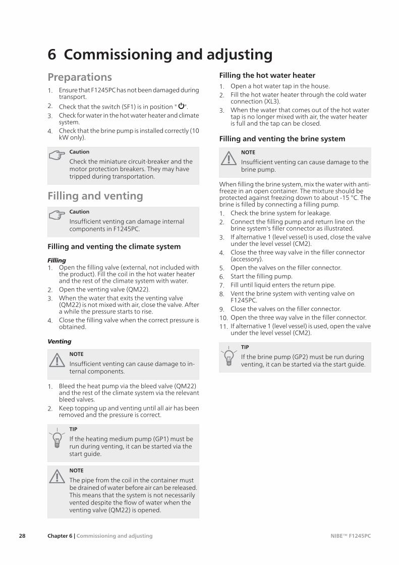
Preparations1. Ensure that F1245PC has not been damaged during
transport.2. Check that the switch (SF1) is in position " ".3. Check for water in the hot water heater and climate
system.4. Check that the brine pump is installed correctly (10
kW only).
Caution
Check the miniature circuit-breaker and themotor protection breakers. They may havetripped during transportation.
Filling and ventingCaution
Insufficient venting can damage internalcomponents in F1245PC.
Filling and venting the climate system
Filling1. Open the filling valve (external, not included with
the product). Fill the coil in the hot water heaterand the rest of the climate system with water.
2. Open the venting valve (QM22).3. When the water that exits the venting valve
(QM22) is not mixed with air, close the valve. Aftera while the pressure starts to rise.
4. Close the filling valve when the correct pressure isobtained.
Venting
NOTE
Insufficient venting can cause damage to in-ternal components.
1. Bleed the heat pump via the bleed valve (QM22)and the rest of the climate system via the relevantbleed valves.
2. Keep topping up and venting until all air has beenremoved and the pressure is correct.
TIP
If the heating medium pump (GP1) must berun during venting, it can be started via thestart guide.
NOTE
The pipe from the coil in the container mustbe drained of water before air can be released.This means that the system is not necessarilyvented despite the flow of water when theventing valve (QM22) is opened.
Filling the hot water heater
1. Open a hot water tap in the house.2. Fill the hot water heater through the cold water
connection (XL3).3. When the water that comes out of the hot water
tap is no longer mixed with air, the water heateris full and the tap can be closed.
Filling and venting the brine system
NOTE
Insufficient venting can cause damage to thebrine pump.
When filling the brine system, mix the water with anti-freeze in an open container. The mixture should beprotected against freezing down to about -15 °C. Thebrine is filled by connecting a filling pump.1. Check the brine system for leakage.2. Connect the filling pump and return line on the
brine system's filler connector as illustrated.3. If alternative 1 (level vessel) is used, close the valve
under the level vessel (CM2).4. Close the three way valve in the filler connector
(accessory).5. Open the valves on the filler connector.6. Start the filling pump.7. Fill until liquid enters the return pipe.8. Vent the brine system with venting valve on
F1245PC.9. Close the valves on the filler connector.10. Open the three way valve in the filler connector.11. If alternative 1 (level vessel) is used, open the valve
under the level vessel (CM2).
TIP
If the brine pump (GP2) must be run duringventing, it can be started via the start guide.
NIBE™ F1245PCChapter 6 | Commissioning and adjusting28
6 Commissioning and adjusting

VVKV
KBin
VBf VBr
KBut
BK / JK
Stängs
P
Connection, heating medium flowXL 1Connection, heating medium returnXL 2Connection, cold waterXL 3Connection, hot waterXL 4Connection, brine inXL 6Connection, brine outXL 7
Symbol key
MeaningSymbol
Shut-off valve
Safety valve
Level vessel
Expansion vessel
Pressure gaugeP
Particle filter
Start guideNOTE
There must be water in the climate systembefore the switch is set to " ".
1. Turn the heat pump's switch (SF1) to "".
2. Follow the instructions in the start guide in theheat pump display. If the start guide does not startwhen you start the heat pump, start it manually inmenu 5.7.
TIP
See page 34 for a more in-depth introductionto the heat pump’s control system (operation,menus etc.).
CommissioningThe first time the heat pump is started a start guide isstarted. The start guide instructions state what needsto carried out at the first start together with a runthrough of the heat pump’s basic settings.
The start guide ensures that the start-up is carried outcorrectly and cannot be bypassed. The start guide canbe started later in menu 5.7.
Caution
As long as the start guide is active, no functionin the installation will start automatically.
The guide will appear at each installation re-start until it is deselected on the last page.
Operation in the start guide
A.
D.C.
B.
A. Page
Here you can see how far you have come in the startguide.
Scroll between the pages of the start guide as follows:1. Turn the control knob until one of the arrows in
the top left corner (at the page number) has beenmarked.
2. Press the OK button to skip between the pages inthe start guide.
29Chapter 6 | Commissioning and adjustingNIBE™ F1245PC

B. Name and menu number
Read what menu in the control system this page of thestart guide is based on. The digits in brackets refer tothe menu number in the control system.
If you want to read more about affected menus eitherread off in the sub-menu or in the installation manualfrom page 38.
C. Option / setting
Make settings for the system here.
D. Help menu
In many menus there is a symbol that indicatesthat extra help is available.
To access the help text:1. Use the control knob to select the help symbol.2. Press the OK button.
The help text often consists of several windows thatyou can scroll between using the control knob.
Post adjustment and ventingPump adjustment, automatic operation
Brine side
To set the correct flow in the brine system the correctspeed must be set for the brine pump. This heat pumphas a brine pump that can automatically controlled.
This automatic control occurs when the compressor isrunning and automatically sets the speed of the brinepump to obtain the optimal temperature differencebetween the supply and return lines. For passive cool-ing operation the brine pump must run at a set speedwhich is set in menu 5.1.9.
Heating medium side
To set the correct flow in the climate system the correctspeed must be set for the heating medium pump. Thisheat pump has a heating medium pump that canautomatically controlled.
This automatic control occurs when the compressor isrunning and automatically sets the speed of the heatingmedium pump, for the present operating mode, toobtain the optimal temperature difference betweenthe supply and return lines. During heating operationthe set DOT (dimensioned outdoor temperature) andtemperature differential in menu 5.1.14 are used in-stead. If necessary the maximum speed of the circula-tion pump can be limited in menu 5.1.11.
NIBE™ F1245PCChapter 6 | Commissioning and adjusting30
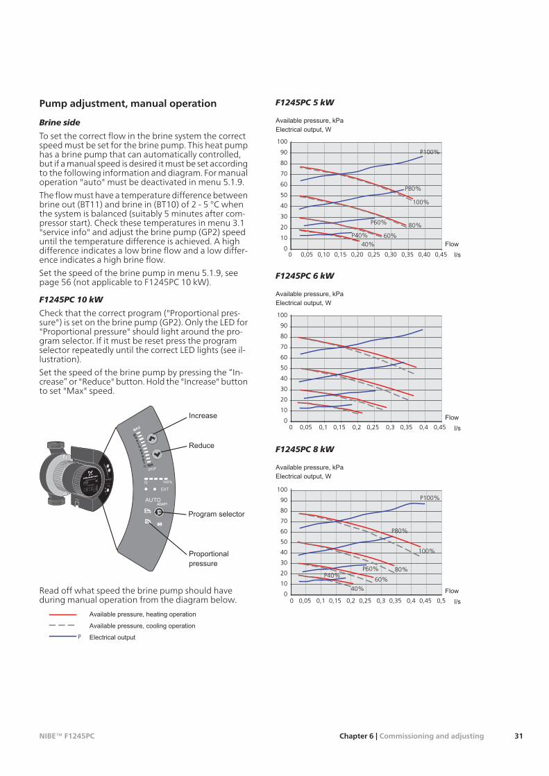
Pump adjustment, manual operation
Brine side
To set the correct flow in the brine system the correctspeed must be set for the brine pump. This heat pumphas a brine pump that can automatically controlled,but if a manual speed is desired it must be set accordingto the following information and diagram. For manualoperation "auto" must be deactivated in menu 5.1.9.
The flow must have a temperature difference betweenbrine out (BT11) and brine in (BT10) of 2 - 5 °C whenthe system is balanced (suitably 5 minutes after com-pressor start). Check these temperatures in menu 3.1"service info" and adjust the brine pump (GP2) speeduntil the temperature difference is achieved. A highdifference indicates a low brine flow and a low differ-ence indicates a high brine flow.
Set the speed of the brine pump in menu 5.1.9, seepage 56 (not applicable to F1245PC 10 kW).
F1245PC 10 kW
Check that the correct program ("Proportional pres-sure") is set on the brine pump (GP2). Only the LED for"Proportional pressure" should light around the pro-gram selector. If it must be reset press the programselector repeatedly until the correct LED lights (see il-lustration).
Set the speed of the brine pump by pressing the “In-crease” or "Reduce" button. Hold the "Increase" buttonto set "Max" speed.
LE
K
MAGNA
Made in Germany
Min.
I1/1
1(A)
(W)
Max.
Min.
P
Max.Min.
Max.
P/N 96917292
PC 0931NIB
1x230-240V 50/60HzTF110
IPX4
1.2518510
0,09 1,0MPa
-10°C
GE025-100 180
EXT
Q 100%
MAX
STOP
AUTOADAPT
Read off what speed the brine pump should haveduring manual operation from the diagram below.
EleffektTillgängligt tryck, kyldrift
P
Tillgängligt tryck, värmedrift
F1245PC 5 kW
0
10
20
30
40
50
60
70
80
90
100
0 0,05 0,10 0,15 0,20 0,25 0,30 0,35 0,40 0,45
Eleffekt, WTillgängligt tryck, kPa
Flödel/s
P100%
100%
P60%
P40%
P80%
80%
60%40%
F1245PC 6 kW
0
10
20
30
40
50
60
70
80
90
100
0 0,05 0,1 0,15 0,2 0,25 0,3 0,35 0,4 0,45
Eleffekt, WTillgängligt tryck, kPa
Flödel/s
F1245PC 8 kW
0
10
20
30
40
50
60
70
80
90
100
0 0,05 0,1 0,15 0,2 0,25 0,3 0,35 0,4 0,45 0,5
Eleffekt, WTillgängligt tryck, kPa
Flödel/s
P100%
100%
P60%P40%
P80%
80%
60%
40%
31Chapter 6 | Commissioning and adjustingNIBE™ F1245PC

F1245PC 10 kW
0
20
40
60
80
100
120
140
160
180
200
0 0,1 0,2 0,3 0,4 0,5 0,6
Eleffekt, WTillgängligt tryck, kPa
Flödel/s
PMax
Max
P7
P5
P9
9
7
5
Heating medium side
To set the correct flow in the climate system the correctspeed must be set for the heating medium pump inthe different operating conditions. This heat pump hasa heating medium pump that can automatically con-trolled, but if a manual speed is desired it must be setaccording to the following information and diagram.For manual operation "auto" must be deactivated inmenu 5.1.11.
The flow must have a suitable temperature differencefor the operation (heating operation: 5 - 10 °C, hotwater regeneration: 8 - 10 °C, pool heating: approx.15 °C) between flow temperature (BT2) and the returntemperature (BT3). Check these temperatures in menu3.1 "service info" and adjust the heating medium pump(GP1) speed until the temperature difference isachieved. A high difference indicates a low heatingmedium flow and a low difference indicates a highheating medium flow.
Set the speed of the heating medium pump in menu5.1.11, see page 57.
Read off what speed the heating medium pump shouldhave during manual operation from the diagrams be-low.
EleffektTillgängligt tryck
P
F1245PC 5 kW
0
10
20
30
40
50
60
0 0,05 0,1 0,15 0,2 0,25 0,3 0,35
Eleffekt, WTillgängligt tryck, kPa
Flödel/s
P100%
100%
P60%
P40%
P80%
80%60%
40%
F1245PC 6 kW
0
10
20
30
40
50
60
0 0,05 0,1 0,15 0,2 0,25 0,3 0,35
Eleffekt, WTillgängligt tryck, kPa
Flödel/s
P100%
P80%
P60%
100%
80%60%
P40%40%
NIBE™ F1245PCChapter 6 | Commissioning and adjusting32

F1245PC 8 kW
0
10
20
30
40
50
60
70
0 0,05 0,1 0,15 0,2 0,25 0,3 0,35 0,4
Eleffekt, WTillgängligt tryck, kPa
Flödel/s
P100%
P80%
P60%
100%
80%
60%P40%40%
F1245PC 10 kW
0
10
20
30
40
50
60
0 0,05 0,1 0,15 0,2 0,25 0,3 0,35
P100%
P80%
P60%
100%
80%60%
P40%40%
Readjusting, venting, heat medium sideAir is initially released from the hot water and ventingmay be necessary. If gurgling sounds can be heard fromthe heat pump or climate system, the entire system willrequire additional venting.
Readjusting, venting, collector side
Level vessel
2/3
LE
K
Check the fluid level in the level vessel(CM2). If the fluid level has dropped, topup the system.1. Close the valve under the vessel.2. Disconnect the connection on top of
the vessel.3. Fill with brine until approx 2/3 of the
vessel is full.4. Reconnect the connector at the top of
the vessel.5. Open the valve under the vessel.
The pressure is raised by closing the valve on the incom-ing main line when the brine pump (GP2) is runningand the level vessel (CM2) is open, so that liquid isdrawn down from the vessel.
Expansion vessel
LEK
If a pressure expansion vessel (CM3) is usedinstead of a level vessel, the pressure levelis checked. If the pressure drops, the sys-tem should be replenished.
Post adjusting the room temperat-ureIf the required room temperature is not obtained, re-adjustment may be necessary.
Cold weather conditionsIf the room temperature is too low, increase "heatingcurve" in menu 1.9.1, one step.If the room temperature is too high, reduce "heatingcurve" in menu 1.9.1, one step.
Warm weather conditionsIf the room temperature is too low, increase "temper-ature" (heating curve offset) in menu 1.1, one step.If the room temperature is too high, reduce "temper-ature" (heating curve offset) in menu 1.1, one step.
33Chapter 6 | Commissioning and adjustingNIBE™ F1245PC
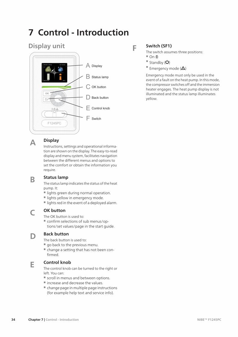
Display unit
DisplayInstructions, settings and operational informa-tion are shown on the display. The easy-to-readdisplay and menu system, facilitates navigationbetween the different menus and options toset the comfort or obtain the information yourequire.
A
Status lampThe status lamp indicates the status of the heatpump. It:
lights green during normal operation.lights yellow in emergency mode.lights red in the event of a deployed alarm.
B
OK buttonThe OK button is used to:
confirm selections of sub menus/op-tions/set values/page in the start guide.
C
Back buttonThe back button is used to:
go back to the previous menu.change a setting that has not been con-firmed.
D
Control knobThe control knob can be turned to the right orleft. You can:
scroll in menus and between options.increase and decrease the values.change page in multiple page instructions(for example help text and service info).
E
Switch (SF1)The switch assumes three positions:
On ()
Standby ( )
Emergency mode ( )
Emergency mode must only be used in theevent of a fault on the heat pump. In this mode,the compressor switches off and the immersionheater engages. The heat pump display is notilluminated and the status lamp illuminatesyellow.
F
NIBE™ F1245PCChapter 7 | Control - Introduction34
7 Control - Introduction

Menu systemWhen the door to the heat pump is opened, the menusystem’s four main menus are shown in the display aswell as certain basic information.
Menu 1 - INDOOR CLIMATESetting and scheduling the indoor climate. See page38.
Menu 2 - HOT WATERSetting and scheduling hot water production. See page46.
Menu 3 - INFODisplay of temperature and other operating informa-tion and access to the alarm log. See page 48.
Menu 4 - HEAT PUMPSetting time, date, language, display, operating modeetc. See page 49.
Menu 5 - SERVICEAdvanced settings. These settings are not available tothe end user. The menu is visible by pressing the Backbutton for 7 seconds. See page 54.
Symbols in the displayThe following symbols can appear in the display duringoperation.
DescriptionSymbol
This symbol appears by the informationsign if there is information in menu 3.1that you should note.
These two symbols indicate whether thecompressor or addition is blocked inF1245PC.
These can, for example, be blocked de-pending on which operating mode is se-lected in menu 4.2, if blocking is sched-uled in menu 4.9.5 or if an alarm has oc-curred that blocks one of them.
Blocking the compressor.
Blocking additional heat.
This symbol appears if lux mode for thehot water is activated.
This symbol indicates the actual speed ofthe fan if the speed has changed fromthe normal setting.
Accessory NIBE FLM required.
This symbol indicates whether F1245PChas contact with NIBE Uplink™.
This symbol indicates whether "holidaysetting" is activated in menu 4.7.
35Chapter 7 | Control - IntroductionNIBE™ F1245PC

Marked mainmenu
Menu number – marked sub menu Name and menu number – main menu
Symbol –main menu
Status information – submenus
Name – sub menusSymbols – sub menus
OperationTo move the cursor, turn the control knob tothe left or the right. The marked position isbrighter and/or has a turned up tab.
Selecting menuTo advance in the menu system select a main menu bymarking it and then pressing the OK button. A newwindow then opens with sub menus.
Select one of the sub menus by marking it and thenpressing the OK button.
Selecting options
In an options menu the current selected option isindicated by a green tick.
To select another option:1. Mark the applicable option. One of the options
is pre-selected (white).2. Press the OK button to confirm the selected
option. The selected option has a green tick.
Setting a value
time & date4.4time
day
year
month
24 hrs
12 h
date
Values to be changed
To set a value:1. Mark the value you want to set using the
control knob.2. Press the OK button. The background of the
value becomes green, which means that youhave accessed the setting mode.
3. Turn the control knob to the right to increasethe value and to the left to reduce the value.
4. Press the OK button to confirm the value youhave set. To change and return to the originalvalue, press the Back button.
NIBE™ F1245PCChapter 7 | Control - Introduction36

Use the virtual keyboard
In some menus where text may require entering, a vir-tual keyboard is available.
Depending on the menu, you can gain access to differ-ent character sets which you can select using the con-trol knob. To change character table, press the Backbutton. If a menu only has one character set the key-board is displayed directly.
When you have finished writing, mark "OK" and pressthe OK button.
Scroll through the windowsA menu can consist of several windows. Turn the con-trol knob to scroll between the windows.
Scroll through the windows in the start guide
1. Turn the control knob until one of the arrows inthe top left corner (at the page number) has beenmarked.
2. Press the OK button to skip between the steps inthe start guide.
Help menuIn many menus there is a symbol that indicatesthat extra help is available.
To access the help text:1. Use the control knob to select the help symbol.2. Press the OK button.
The help text often consists of several windows thatyou can scroll between using the control knob.
37Chapter 7 | Control - IntroductionNIBE™ F1245PC

Menu 1 - INDOOR CLIMATE Overview
1.1 - temperature1 - INDOOR CLIMATE
1.2 - ventilation *
1.3.1 - heating1.3 - scheduling
1.3.2 - cooling
1.3.3 - ventilation *
1.9.1 - heating curve1.9 - advanced
1.9.2 - external adjustment
1.9.3 - min. flow line temp.
1.9.4 - room sensor settings
1.9.5 - cooling settings
1.9.6 - fan return time *
1.9.7 - own curve
1.9.8 - point offset
1.9.9 - night cooling
* Accessories are needed.
Sub-menus
For the menu INDOOR CLIMATE there are several sub-menus. Status information for the relevant menu canbe found on the display to the right of the menus.
temperature Setting the temperature for the climatesystem. The status information shows the set valuesfor the climate system.
ventilation Setting the fan speed. The status informa-tion shows the selected setting. This menu is only dis-played if the exhaust air module is connected (access-ory).
scheduling Scheduling heating, cooling and ventila-tion. Status information "set" is displayed if you set aschedule but it is not active now, "holiday setting" isdisplayed if the vacation schedule is active at the sametime as the schedule (the vacation function is priorit-ised), "active" displays if any part of the schedule isactive, otherwise it displays " off".
advanced Setting of heat curve, adjusting with extern-al contact, minimum value for supply temperature,room sensor and cooling function.
Menu 1.1 - temperatureIf the house has several climate systems, this is indicatedon the display by a thermometer for each system.
If the heat pump has an accessory for cooling or integ-rated cooling function this is shown in the display withan extra tab.
Set the temperature (with room sensors installedand activated):
Setting range: 5 - 30 °C
Default value: 20
The value in the display appears as a temperature in°C if the heating system is controlled by a room sensor.
To change the room temperature, use the control knobto set the desired temperature in the display. Confirmthe new setting by pressing the OK button. The newtemperature is shown on the right-hand side of thesymbol in the display.
Setting the temperature (without room sensorsactivated):
Setting range: -10 to +10
Default value: 0
The display shows the set values for heating (curveoffset). To increase or reduce the indoor temperature,increase or reduce the value on the display.
Use the control knob to set a new value. Confirm thenew setting by pressing the OK button.
The number of steps the value has to be changed toachieve a degree change of the indoor temperaturedepends on the heating installation. One step is usuallyenough but in some cases several steps may be re-quired.
Setting the desired value. The new value is shown onthe right-hand side of the symbol in the display.
Caution
An increase in the room temperature can beslowed by the thermostats for the radiators orunder floor heating. Therefore, open thethermostats fully, except in those rooms wherea cooler temperature is required, e.g. bed-rooms.
NIBE™ F1245PCChapter 8 | Control - Menus38
8 Control - Menus

TIP
Wait 24 hours before making a new setting,so that the room temperature has time tostabilise.
If it is cold outdoors and the room temperatureis too low, increase the curve slope in menu1.9.1 by one increment.
If it is cold outdoors and the room temperatureis too high, lower the curve slope menu 1.9.1by one increment.
If it is warm outdoors and the room temperat-ure is too low, increase the value in menu 1.1by one increment.
If it is warm outdoors and the room temperat-ure is too high, reduce the value in menu 1.1by one increment.
Menu 1.2 - ventilation (accessory required)
Setting range: normal and speed 1-4
Default value: normal
The ventilation in the accommodation can be tempor-arily increased or reduced here.
When you have selected a new speed a clock starts acount down. When the time has counted down theventilation speed returns to the normal setting.
If necessary, the different return times can be changedin menu 1.9.6.
The fan speed is shown in brackets (in percent) aftereach speed alternative.
TIP
If longer time changes are required use theholiday function or scheduling.
Menu 1.3 - schedulingIn the menu scheduling indoor climate (heating/cool-ing/ventilation) is scheduled for each weekday.
You can also schedule a longer period during a selectedperiod (vacation) in menu 4.7.
Menu 1.3.1 - heatingIncreases or decreases in the accommodation temper-ature can be scheduled here for up to three time peri-ods per day. If a room sensor is installed and activatedthe desired room temperature (°C) is set during thetime period. Without an activated room sensor thedesired change is set (of setting in menu 1.1). One stepis usually enough to change the room temperature byone degree, but in some cases several steps may berequired.
Schedule: The schedule to be changed is selected here.
Activated: Scheduling for the selected period is activ-ated here. Set times are not affected at deactivation.
System: Which climate system the schedule is for isselected here. This alternative is only displayed if morethan one climate system is present.
Day: Select which day or days of the week the scheduleis to apply to here. To remove the scheduling for aparticular day, the time for that day must be reset bysetting the start time to the same as the stop time. Ifthe line "all" is used, all days in the period are set forthese times.
Time period: The start and stop time for the selectedday for scheduling are selected here.
Adjusting:How much the heating curve is to be offsetin relation to menu 1.1 during scheduling is set here.If the rooms sensor is installed the desired room tem-perature is set in °C.
Conflict: If two settings conflict with each other a redexclamation mark is displayed.
TIP
If you wish to set similar scheduling for everyday of the week start by filling in “all” and thenchanging the desired days.
Caution
If the stop time is before the start time itmeans that the period extends past midnight.Scheduling always starts on the date that thestart time is set for.
Changes of temperature in accommodationtake time. For example, short time periods incombination with underfloor heating will notgive a noticeable difference in room temperat-ure.
39Chapter 8 | Control - MenusNIBE™ F1245PC

Menu 1.3.2 - coolingHere you can schedule when cooling is permitted inthe accommodation for up to two different time peri-ods per day.
Schedule: The schedule to be changed is selected here.
Activated: Scheduling for the selected period is activ-ated here. Set times are not affected at deactivation.
Day: Select which day or days of the week the scheduleis to apply to here. To remove the scheduling for aparticular day, the time for that day must be reset bysetting the start time to the same as the stop time. Ifthe line "all" is used, all days in the period are set forthese times.
Time period: The start and stop time for the selectedday for scheduling are selected here.
Adjusting:Whether or not cooling is permitted duringscheduling is set here.
Conflict: If two settings conflict with each other a redexclamation mark is displayed.
TIP
If you wish to set similar scheduling for everyday of the week start by filling in “all” and thenchanging the desired days.
Caution
If the stop time is before the start time itmeans that the period extends past midnight.
Scheduling always starts on the date that thestart time is set for.
Menu1.3.3 - ventilation (accessory required)Increases or decreases in the ventilation to the accom-modation can be scheduled here for up to two timeperiods per day.
Schedule: The schedule to be changed is selected here.
Activated: Scheduling for the selected period is activ-ated here. Set times are not affected at deactivation.
Day: Select which day or days of the week the scheduleis to apply to here. To remove the scheduling for aparticular day, the time for that day must be reset bysetting the start time to the same as the stop time. Ifthe line "all" is used, all days in the period are set forthese times.
Time period: The start and stop time for the selectedday for scheduling are selected here.
Adjusting: The desired fan speed is set here.
Conflict: If two settings conflict with each other a redexclamation mark is displayed.
TIP
If you wish to set similar scheduling for everyday of the week start by filling in “all” and thenchanging the desired days.
Caution
If the stop time is before the start time itmeans that the period extends past midnight.Scheduling always starts on the date that thestart time is set for.
A significant change over a longer period oftime may cause poor indoor environment andworse operating economy.
NIBE™ F1245PCChapter 8 | Control - Menus40

Menu 1.9 - advancedMenu advanced has orange text and is intended forthe advanced user. This menu has several sub-menus.
heating curve Setting the heating curve slope.
external adjustment Setting the heat curve offsetwhen the external contact is connected.
min. flow line temp. Setting minimum permitted flowline temperature.
room sensor settings Settings regarding the roomsensor.
cooling settings Settings for cooling.
fan return time Fan return time settings in the eventof temporary ventilation speed change.
own curve Setting own heat curve.
point offset Setting the offset of the heating curve ata specific outdoor temperature.
night cooling Setting night cooling.
Menu 1.9.1 - heating curve
heating curve
Setting range: 0 - 15
Default value: 9
In the menu heating curve the so-called heating curvefor your house can be viewed. The task of the heatingcurve is to give an even indoor temperature, regardlessof the outdoor temperature, and thereby energy effi-cient operation. It is from this heating curve that theheat pump’s control computer determines the temper-ature of the water to the heating system, flow linetemperature, and therefore the indoor temperature.You can select heating curve and read off how the flowline temperature changes at different outdoor temper-atures here.
Curve coefficient
30
40
50
60
70°C
- 40°CUTETEMPERATUR
- 10010 - 20 - 30
Brantare kurvlutning
The slope of the heating curve indicates how manydegrees the supply temperature is to be increased/re-duced when the outdoor temperature drops/increases.A steeper slope means a higher supply temperature ata certain outdoor temperature.
The optimum slope depends on the climate conditionsin your location, if the house has radiators or underfloor heating and how well insulated the house is.
The heating curve is set when the heating installationis installed, but may need adjusting later. Thereafterthe heating curve should not need further adjustment.
Caution
In the event of making fine adjustments forthe indoor temperature, the heat curve mustbe offset up or down instead, this is done inmenu 1.1 temperature .
Curve offset
30
40
50
60
70°C
- 40°CUTETEMPERATUR
- 10010 - 20 - 30
Förskjuten värmekurva
An offset of the heating curve means that the supplytemperature changes as much for all the outdoortemperatures, e.g. that a curve offset of +2 steps in-creases the supply temperature by 5 °C at all outdoortemperatures.
41Chapter 8 | Control - MenusNIBE™ F1245PC

Flow line temperature– maximum and minimumvalues
30
40
50
60
70°C
- 40°CUTETEMPERATUR
- 10010 - 20 - 30
Maximivärde
Minimivärde
Because the flow line temperature cannot be calculatedhigher than the set maximum value or lower than theset minimum value the heating curve flattens out atthese temperatures.
Caution
Underfloor heating systems are normally maxflow line temperature set between 35 and 45°C.
Check the max temperature for your floor withyour installer/floor supplier.
The figure at the end of the curve indicates the curveslope. The figure beside the thermometer gives thecurve offset. Use the control knob to set a new value.Confirm the new setting by pressing the OK button.
Curve 0 is an own heating curve created in menu 1.9.7.
To select another heat curve (slope):
NOTE
If you only have one heating system, thenumber of the curve is already marked whenthe menu window opens.
1. Select the system (if more than one) for which theheat curve is to be changed.
2. When the system selection has been confirmedthe heat curve number is marked.
3. Press the OK button to access the setting mode4. Select a new heating curve. The heat curves are
numbered from 0 to 15, the greater the number,the steeper the slope and the greater the supplytemperature. Heating curve 0 means that owncurve (menu 1.9.7) is used.
5. Press the OK button to exit the setting.
To read off a heating curve:1. Turn the control knob so that the ring on the shaft
with the outdoor temperature is marked.2. Press the OK button.3. Follow the grey line up to the heat curve and out
to the left to read off the value for the supplytemperature at the selected outdoor temperature.
4. You can now select to take read outs for differentoutdoor temperatures by turning the control knobto the right or left and read off the correspondingflow temperature.
5. Press the OK or Back button to exit read off mode.
TIP
Wait 24 hours before making a new setting,so that the room temperature has time tostabilise.
If it is cold outdoors and the room temperatureis too low, increase the curve slope by one in-crement.
If it is cold outdoors and the room temperatureis too high, lower the curve slope by one incre-ment.
If it is warm outdoors and the room temperat-ure is too low, increase the curve offset by oneincrement.
If it is warm outdoors and the room temperat-ure is too high, lower the curve offset by oneincrement.
Menu 1.9.2 - external adjustment
climate system
Setting range: -10 to +10 or desired room temperat-ure if the room sensor is installed.
Default value: 0
Connecting an external contact, for example, a roomthermostat or a timer allows you to temporarily orperiodically raise or lower the room temperature. Whenthe contact is on, the heat curve offset is changed bythe number of steps selected in the menu. If a roomsensor is installed and activated the desired roomtemperature (°C) is set.
If there is more than one climate system the settingcan be made separately for each system.
Menu 1.9.3 - min. flow line temp.
climate system
Setting range: 5-70 °C
Default value: 20 °C
Set the minimum temperature on the supply temper-ature to the climate system. This means that F1245PCnever calculates a temperature lower than that sethere.
If there is more than one climate system the settingcan be made separately for each system.
NIBE™ F1245PCChapter 8 | Control - Menus42

TIP
The value can be increased if you have, for ex-ample, a cellar that you always want to heat,even in summer.
You may also need to increase the value in"stop heating" menu 4.9.2 "auto mode set-ting".
Menu 1.9.4 - room sensor settings
factor system
Setting range: 0.0 - 6.0
Default value: 2.0
Room sensors to control the room temperature can beactivated here.
Here you can set a factor that determines how muchthe supply temperature is to be affected by the differ-ence between the desired room temperature and theactual room temperature. A higher value gives agreater change of the heating curve's set offset.
If several climate systems are installed the above set-tings can be made for the relevant systems.
Menu 1.9.5 - cooling settings
min. temp. cooling flow
Setting range: 5 - 30 °C
Default value: 17
cooling flow temp. at +20°C
Setting range: 5 - 30 °C
Default value: 20
cooling flow temp. at +40°C
Setting range: 5 - 30 °C
Default value: 20
set pt value cool/heat sensor
Setting range: 5 - 40 °C
Default value: 21
heat at room under temp.
Setting range: 0.5 - 10.0 °C
Default value: 1.0
cool at room over temp.
Setting range: 0.5 - 10.0 °C
Default value: 1.0
start passive cooling
Setting range: 10 – 200
Default value: 30
start active cooling
Setting range: 10 – 300
Default value: 90
time betw. switch heat/cool
Setting range: 0 - 48 h
Default value: 2
mixing valve amplifier
Setting range: 0.1 –10.0
Default value: 1.0
mixing valve step delay
Setting range: 10 – 300 s
Default values: 30 s
You can use F1245PC to cool the house during hotperiods of the year.
NOTE
Cooling flow line must be set with regard towhich climate system is connected. For ex-ample, floor cooling with too low cooling flowline can cause condensation precipitation,which in the worst instance could lead tomoisture damage.
min. temp. cooling flow
Set the minimum temperature on the supply temper-ature to the climate system during cooling operation.This means that F1245PC never calculates a temperat-ure lower than that set here.
cooling flow temp. at +20°C
Set the desired temperature on the flow temperatureto the climate system during cooling operation whenthe outdoor temperature is +20 °C. F1245PC then at-tempts to get as close to the set temperature as pos-sible.
cooling flow temp. at +40°C
Set the desired temperature on the flow temperatureto the climate system during cooling operation whenthe outdoor temperature is +40 °C. F1245PC then at-tempts to get as close to the set temperature as pos-sible.
43Chapter 8 | Control - MenusNIBE™ F1245PC

use system 2 in cool mode - use system 4 in coolmode
Caution
This setting option only appears if "passive/act-ive cooling 2-pipe" or "passive cooling 2-pipe"is activated in menu 5.2.4.
Here you select whether you want to use climate sys-tem 2 - 4 in cooling mode (if there is more than one).If this function is activated, you can set "cooling flowtemp. at +20°C" and "cooling flow temp. at +40°C" foreach climate system where the function is activated.
use room sensor
Here you can set whether room temperature sensorsare to be used in cooling mode.
set pt value cool/heat sensor
Caution
This setting option only appears if sensors forcooling/heating (BT74) are installed and activ-ated in F1245PC.
Here you can set at which indoor temperature F1245PCis to shift between heating respectively cooling opera-tion.
heat at room under temp.
Caution
This setting option only appears if a roomtemperature sensor is connected to F1245PCand has been activated.
Here you can set how far the room temperature candrop below the desired temperature before F1245PCswitches to heating operation.
start passive cooling
Caution
This setting option only appears if "passive/act-ive cooling" is activated in menu 5.2.4.
Here you can set when passive cooling is to start.
Degree minutes are a measurement of the currentheating demand in the house and determine when thecompressor, cooling operation respectively additionalheat will start/stop.
start active cooling
Caution
This setting option only appears if "passive/act-ive cooling" is activated in menu 5.2.4.
Here you can set when active cooling is to start.
Degree minutes are a measurement of the currentheating demand in the house and determine when thecompressor, cooling operation respectively additionalheat will start/stop.
cool at room over temp.
Caution
This setting option only appears if a roomtemperature sensor is connected to F1245PCand has been activated.
Here you can set how high the room temperature canincrease above the desired temperature beforeF1245PC switches to cooling operation.
time betw. switch heat/cool
Here you can set how long F1245PC is to wait beforeit returns to heating mode when the cooling demandhas ceased or vice versa.
close mix. valves in cool mode
Caution
This setting option only appears if passivecooling is activated in menu 5.2.4.
If the heat pump is connected to more than one climatesystem condensation may occur in these if they are notintended for cooling.
To avoid this check "close mix. valves in cool mode",which means that the sub-shunts for the extra climatesystems close when cooling operation is activated.
mixing valve amplifier andmixing valve stepdelay
Caution
This setting option only appears if passivecooling is activated in menu 5.2.4.
Shunt reinforcement and shunt wait time for thecooling system are set here.
Menu 1.9.6 - fan return time (accessory re-quired)
speed 1-4
Setting range: 1 – 99 h
Default value: 4 h
Here you select the return time for temporary speedchange (speed 1-4) on the ventilation in menu 1.2.
Return time is the time it takes before ventilation speedreturns to normal.
NIBE™ F1245PCChapter 8 | Control - Menus44
Menu 1.9.7 - own curve
supply temperature
Setting range: 0 – 80 °C
You can create your own heating curve here, if thereare special requirements, by setting the desired supplytemperatures for different outdoor temperatures.
Caution
Curve 0 in menu 1.9.1 must be selected for thiscurve to apply.
Menu 1.9.8 - point offset
outdoor temp. point
Setting range: -40 – 30 °C
Default value: 0 °C
change in curve
Setting range: -10 – 10 °C
Default value: 0 °C
Select a change in the heating curve at a certain out-door temperature here. One step is usually enough tochange the room temperature by one degree, but insome cases several steps may be required.
The heat curve is affected at ± 5 °C from set outdoortemp. point.
It is important that the correct heating curve is selectedso that the room temperature is experienced as even.
TIP
If it is cold in the house, at, for example -2 °C,"outdoor temp. point" is set to "-2" and"change in curve" is increased until the desiredroom temperature is maintained.
Caution
Wait 24 hours before making a new setting,so that the room temperature has time tostabilise.
Menu 1.9.9 - night cooling (accessory re-quired)
start temp. exhaust air
Setting range: 20 – 30 °C
Default value: 25 °C
min diff. outdoor-exhaust
Setting range: 3 – 10 °C
Default value: 6 °C
Activate night cooling here.
When the temperature in the house is high and theoutdoor temperature is lower, a cooling effect can beobtained by forcing the ventilation.
If the temperature difference between the exhaust airand the outdoor air temperature is greater than theset value ("min diff. outdoor-exhaust") and the exhaustair temperature is higher than the set value ("starttemp. exhaust air") run the ventilation at speed 4 untilone of the conditions is no longer met.
Caution
Night cooling can only be activated whenhouse heating has been deactivated. This isdone in menu 4.2.
45Chapter 8 | Control - MenusNIBE™ F1245PC

Menu 2 - HOT WATER Overview
2.1 - temporary lux2 - HOT WATER
2.2 - comfort mode
2.3 - scheduling
2.9.1 - periodic increases2.9 - advanced
2.9.2 - hot water recirc.
Sub-menus
For the menu HOT WATER there are several sub-menus. Status information for the relevant menu canbe found on the display to the right of the menus.
temporary lux Activation of temporary increase in thehot water temperature. Status information displays“off" or what length of time of the temporary temper-ature increase remains.
comfort mode Setting hot water comfort. The statusinformation displays what mode is selected, "economy","normal" or "luxury".
scheduling Scheduling hot water comfort. Status in-formation "set" displays if any part of the schedule isactive at present, "holiday setting" displays if vacationsetting is in progress (menu 4.7), otherwise it displays"off".
advanced Setting periodic increase in the hot watertemperature.
Menu 2.1 - temporary lux
Setting range: 3, 6 and 12 hours and mode "off"
Default value: "off"
When hot water requirement has temporarily increasedthis menu can be used to select an increase in the hotwater temperature to lux mode for a selectable time.
Caution
If comfort mode "luxury" is selected in menu2.2 no further increase can be carried out.
The function is activated immediately when a timeperiod is selected and confirmed using the OK button.The remaining time for the selected setting is shownto the right.
When the time has run out F1245PC returns to themode set in menu 2.2.
Select “off" to switch off temporary lux .
Menu 2.2 - comfort mode
Setting range: economy, normal, luxury
Default value: normal
The difference between the selectable modes is thetemperature of the hot tap water. Higher temperaturemeans that the hot water lasts longer.
economy: This mode gives less hot water than theother, but is more economical. This mode can be used
in smaller households with a small hot water require-ment.
normal: Normal mode gives a larger amount of hotwater and is suitable for most households.
luxury: Lux mode gives the greatest possible amountof hot water. In this mode the immersion heater maybe partially used to heat hot water, which may increaseoperating costs.
Menu 2.3 - schedulingWhat hot water comfort the heat pump is to work withcan be scheduled here for up to two different timeperiods per day.
Scheduling is activated/deactivated by ticking/untick-ing"activated". Set times are not affected at deactiva-tion.
all
mon
tues
we
thur
fri
sat
sun
activated
schedule 2schedule 1
SCHEDULING HOT WATER 2.3
normal
Time period AdjustingDay
Activated Schedule
Conflict
Schedule: The schedule to be changed is selected here.
Activated: Scheduling for the selected period is activ-ated here. Set times are not affected at deactivation.
Day: Select which day or days of the week the scheduleis to apply to here. To remove the scheduling for aparticular day, the time for that day must be reset bysetting the start time to the same as the stop time. Ifthe line "all" is used, all days in the period are set forthese times.
Time period: The start and stop time for the selectedday for scheduling are selected here.
Adjusting: Set the hot water comfort that is to applyduring scheduling here.
Conflict: If two settings conflict with each other a redexclamation mark is displayed.
NIBE™ F1245PCChapter 8 | Control - Menus46
TIP
If you wish to set similar scheduling for everyday of the week start by filling in “all” and thenchanging the desired days.
Caution
If the stop time is earlier in the day than thestart time it means that the period extendspast midnight.
Scheduling always starts on the date that thestart time is set for.
Menu 2.9 - advancedMenu advanced has orange text and is intended forthe advanced user. This menu has several sub-menus.
Menu 2.9.1 - periodic increases
period
Setting range: 1 - 90 days
Default value: 14 days
start time
Setting range: 00:00 - 23:00
Default value: 00:00
To prevent bacterial growth in the water heater, thecompressor and the immersion heater can increase thehot water temperature for a short time at regular inter-vals.
The length of time between increases can be selectedhere. The time can be set between 1 and 90 days.Factory setting is 14 days. Untick "activated" to switchoff the function.
Menu 2.9.2 - hot water recirc.
operating time
Setting range: 1 - 60 min
Default value: 60 min
downtime
Setting range: 0 - 60 min
Default value: 0 min
Set the hot water circulation for up to three periodsper day here. During the set periods the hot water cir-culation pump will run according to the settings above.
"operating time" decide how long the hot water circu-lation pump must run per operating instance.
"downtime" decide how long the hot water circulationpump must be stationary between operating instances.
47Chapter 8 | Control - MenusNIBE™ F1245PC
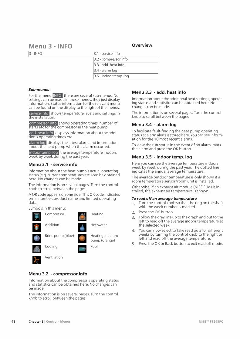
Menu 3 - INFO Overview
3.1 - service info3 - INFO
3.2 - compressor info
3.3 - add. heat info
3.4 - alarm log
3.5 - indoor temp. log
Sub-menus
For the menu INFO there are several sub-menus. Nosettings can be made in these menus, they just displayinformation. Status information for the relevant menucan be found on the display to the right of the menus.
service info shows temperature levels and settings inthe installation.
compressor info shows operating times, number ofstarts etc for the compressor in the heat pump.
add. heat info displays information about the addi-tion’s operating times etc.
alarm log displays the latest alarm and informationabout the heat pump when the alarm occurred.
indoor temp. log the average temperature indoorsweek by week during the past year.
Menu 3.1 - service infoInformation about the heat pump’s actual operatingstatus (e.g. current temperatures etc.) can be obtainedhere. No changes can be made.
The information is on several pages. Turn the controlknob to scroll between the pages.
A QR code appears on one side. This QR code indicatesserial number, product name and limited operatingdata.
Symbols in this menu:HeatingCompressor
Hot waterAddition
Heating mediumpump (orange)
Brine pump (blue)
PoolCooling
Ventilation
Menu 3.2 - compressor infoInformation about the compressor’s operating statusand statistics can be obtained here. No changes canbe made.
The information is on several pages. Turn the controlknob to scroll between the pages.
Menu 3.3 - add. heat infoInformation about the additional heat settings, operat-ing status and statistics can be obtained here. Nochanges can be made.
The information is on several pages. Turn the controlknob to scroll between the pages.
Menu 3.4 - alarm logTo facilitate fault-finding the heat pump operatingstatus at alarm alerts is stored here. You can see inform-ation for the 10 most recent alarms.
To view the run status in the event of an alarm, markthe alarm and press the OK button.
Menu 3.5 - indoor temp. logHere you can see the average temperature indoorsweek by week during the past year. The dotted lineindicates the annual average temperature.
The average outdoor temperature is only shown if aroom temperature sensor/room unit is installed.
Otherwise, if an exhaust air module (NIBE FLM) is in-stalled, the exhaust air temperature is shown.
To read off an average temperature1. Turn the control knob so that the ring on the shaft
with the week number is marked.2. Press the OK button.3. Follow the grey line up to the graph and out to the
left to read off the average indoor temperature atthe selected week.
4. You can now select to take read outs for differentweeks by turning the control knob to the right orleft and read off the average temperature.
5. Press the OK or Back button to exit read off mode.
NIBE™ F1245PCChapter 8 | Control - Menus48

Menu 4 - HEAT PUMP Overview
4.1.1 - pool *4.1 - plus functions *4 - HEAT PUMP
4.1.2 - pool 2 *
4.1.3.1 - nibe uplink4.1.3 - internet
4.1.3.8 - tcp/ip settings
4.1.3.9 - proxy settings
4.1.4 - sms *
4.1.5 - SG Ready
4.2 - op. mode
4.3 - my icons
4.4 - time & date
4.6 - language
4.7 - holiday setting
4.9.1 - op. prioritisation4.9 - advanced
4.9.2 - auto mode setting
4.9.3 - degree minute setting
4.9.4 - factory setting user
4.9.5 - schedule blocking
* Accessory needed.
Sub-menus
For the menu HEAT PUMP there are several sub-menus. Status information for the relevant menu canbe found on the display to the right of the menus.
plus functions Settings applying to any installed extrafunctions in the heating system.
op. mode Activation of manual or automatic operat-ing mode. The status information shows the selectedoperating mode.
my icons Settings regarding which icons in the heatpump's user interface that are to appear in the slotwhen the door is closed.
time & date Setting current time and date.
language Select the language for the display here.The status information shows the selected language.
holiday setting Vacation scheduling heating, hot waterand ventilation. Status information "set" is displayed ifyou set a vacation schedule but it is not active at themoment, "active" is displayed if any part of the vacationschedule is active, otherwise it displays " off".
advanced Setting heat pump work mode.
Menu 4.1 - plus functionsSettings for any additional functions installed inF1245PC can be made in the sub menus.
Menu4.1.1 - 4.1.2 - pool 1 - pool 2 (accessoryis required)
start temp
Setting range: 5.0 - 80.0 °C
Default value: 22.0 °C
stop temperature
Setting range: 5.0 - 80.0 °C
Default value: 24.0 °C
Select whether the pool control is to be activated,within what temperatures (start and stop temperature)pool heating must occur and how many compressorsmay work against the pool at the same time.
When the pool temperature drops below the set starttemperature and there is no hot water or heating re-quirement, F1245PC starts pool heating.
Untick "activated" to switch off the pool heating.
Caution
The start temperature cannot be set to a valuethat is higher than the stop temperature.
Menu 4.1.3 - internetHere you make settings for connecting F1245PC to theinternet.
NOTE
For these functions to work the network cablemust be connected.
49Chapter 8 | Control - MenusNIBE™ F1245PC
Menu 4.1.3.1 - nibe uplinkHere you can manage the installation's connection toNIBE Uplink™ (http://www.nibeuplink.com) and seethe number of users connected to the installation viathe internet.
A connected user has a user account in NIBE Uplink™which have been given permission to control and/ormonitor your installation.
Request new connection string
To connect a user account on NIBE Uplink™ to yourinstallation, you must request a unique connectionstring.1. Mark “request new connection string" and press
the OK button.2. The installation now communicates with NIBE Up-
link™ to create a connection string.3. When a connection string has been received, it is
shown in this menu at "connection string" and isvalid for 60 minutes.
Disconnect all users1. Mark “switch off all users" and press the OK button.2. The installation now communicates with NIBE Up-
link™ to release your installation from all connec-ted users via the internet.
NOTE
After disconnecting all users none of them canmonitor or control your installation via NIBEUplink™ without requesting a new connectionstring.
Menu 4.1.3.8 - tcp/ip settingsYou can set TCP/IP settings for your installation here.
Automatic setting (DHCP)1. Tick “automatic". The installation now receives the
TCP/IP settings using DHCP.2. Mark “confirm" and press the OK button.
Manual setting1. Untick "automatic", you now have access to several
setting options.2. Mark “ip-address" and press the OK button.3. Enter the correct details via the virtual keypad.4. Mark “OK" and press the OK button.5. Repeat 1 - 3 for "net mask", "gateway" and "dns".6. Mark “confirm" and press the OK button.
Caution
The installation cannot connect to the internetwithout the correct TCP/IP settings. If unsureabout applicable settings use the automaticmode or contact your network administrator(or similar) for further information.
TIP
All settings made since opening the menu canbe reset by marking "reset" and pressing theOK button.
Menu 4.1.3.9 - proxy settingsYou can set proxy settings for your installation here.
Proxy settings are used to give connection informationto a intermediate server (proxy server) between theinstallation and Internet. These settings are primarilyused when the installation connects to the Internet viaa company network. The installation supports proxyauthentication of the HTTP Basic and HTTP Digest type.
If unsure about applicable settings use the preset set-tings or contact your network administrator (or similar)for further information.
Setting1. Tick “use proxy" if you do not want to use a proxy.2. Mark “server" and press the OK button.3. Enter the correct details via the virtual keypad.4. Mark “OK" and press the OK button.5. Repeat 1 - 3 for "port", "user name" and "pass-
word".6. Mark “confirm" and press the OK button.
TIP
All settings made since opening the menu canbe reset by marking "reset" and pressing theOK button.
Menu 4.1.4 - sms (accessory is required)Make settings for the accessory SMS 40 here.
Add the mobile numbers that are to have access tochange and receive status information from the heatpump. Mobile numbers must include country code e.g.+46 XXXXXXXX.
If you want to receive an SMS message in the event ofthe alarm mark the box to the right of the telephonenumber.
NOTE
Telephone numbers provided must be able toreceive SMS messages.
Menu 4.1.5 - SG ReadyThis function can only be used in mains networks thatsupport the "SG Ready"-standard (Germany).
Make settings for the function "SG Ready" here.
affect room temperature
Here you set whether room temperature should beaffected when activating "SG Ready".
With low price mode of "SG Ready" the parallel offsetof the indoor temperature is increased by "+1". If aroom sensor is installed and activated, the desired roomtemperature increases by 1 °C.
NIBE™ F1245PCChapter 8 | Control - Menus50

With over capacity mode of "SG Ready" the paralleloffset for the indoor temperature is increased by"+2".If a room sensor is installed and activated, the desiredroom temperature increases by 2 °C.
affect hot water
Here you set whether the temperature of the hot watershould be affected when activating "SG Ready".
With low price mode on "SG Ready" the stop temper-ature of the hot water is set as high as possible at onlycompressor operation (immersion heater not permit-ted).
With over capacity mode of "SG Ready" the hot wateris set to "luxury" (immersion heater permitted).
affect cooling
Here you set whether room temperature during coolingoperation should be affected when activating "SGReady".
With low price mode of "SG Ready" and cooling oper-ation the indoor temperature is not affected.
With over capacity mode of "SG Ready" and coolingoperation the parallel offset for the indoor temperatureis reduced by"-1". If a room sensor is installed and ac-tivated, the desired room temperature decreases by 1°C.
affect pool temperature (accessories required)
Here you set whether pool temperature should be af-fected when activating "SG Ready".
With low price mode of "SG Ready" the desired pooltemperature (start and stop temperature) is increasedby 1 °C.
With over capacity mode of "SG Ready" the desiredpool temperature (start and stop temperature) is in-creased by 2 °C.
NOTE
The function must be connected to two AUXinputs and activated in menu 5.4.
Menu 4.2 - op. mode
op. mode
Setting range: auto, manual, add. heat only
Default value: auto
functions
Setting range: compressor, addition, heating, cooling
The heat pump operating mode is usually set to "auto".It is also possible to set the heat pump to "add. heatonly", but only when an addition is used, or "manual"and select yourself what functions are to be permitted.
Change the operating mode by marking the desiredmode and pressing the OK button. When an operatingmode is selected it shows what in the heat pump ispermitted (crossed out = not permitted) and selectablealternatives to the right. To select selectable functionsthat are permitted or not you mark the function usingthe control knob and press the OK button.
Operating mode auto
In this operating mode the heat pump automaticallyselects what functions are permitted.
Operating mode manual
In this operating mode you can select what functionsare permitted. You cannot deselect "compressor" inmanual mode.
Operating mode add. heat only
In this operating mode the compressor is not activeand only additional heating is used.
Caution
If you choose mode "add. heat only" the com-pressor is deselected and there is a higher op-erating cost.
Functions
"compressor" is that which produces heating and hotwater for the accommodation. If "compressor" isdeselected, a symbol in the main menu on the heatpump symbol is displayed. You cannot deselect "com-pressor" in manual mode.
"addition" is what helps the compressor to heat theaccommodation and/or the hot water when it cannotmanage the whole requirement alone.
"heating" means that you get heat in the accommod-ation. You can deselect the function when you do notwish to have heating running.
"cooling" means that you get cooling in the accommod-ation in hot weather. You can deselect the functionwhen you do not wish to have the cooling running.This alternative requires an accessory for cooling or ifthe heat pump has a built in function for cooling.
Caution
If you deselect "addition" it may mean thatsufficient heating in the accommodation is notachieved.
Menu 4.3 - my iconsYou can select what icon should be visible when thedoor to F1245PC is closed. You can select up to 3 icons.If you select more, the ones you selected first will disap-pear. The icons are displayed in the order you selectedthem.
Menu 4.4 - time & dateSet time and date, display mode and time zone here.
TIP
Time and date are set automatically if the heatpump is connected to NIBE Uplink™. To obtainthe correct time, the time zone must be set.
Menu 4.6 - languageChoose the language that you want the informationto be displayed in here.
51Chapter 8 | Control - MenusNIBE™ F1245PC

Menu 4.7 - holiday settingTo reduce energy consumption during a holiday youcan schedule a reduction in heating and hot watertemperature. Cooling, ventilation and pool can also bescheduled if the functions are connected.
If a room sensor is installed and activated the desiredroom temperature (°C) is set during the time period.This setting applies to all climate systems with roomsensors.
If a room sensor is not activated, the desired offset ofthe heating curve is set. This setting applies to all cli-mate systems without room sensors. One step is usuallyenough to change the room temperature by one de-gree, but in some cases several steps may be required.
Vacation scheduling starts at 00:00 on the start dateand stops at 23:59 on the stop date.
TIP
Complete holiday setting about a day beforeyour return so that room temperature and hotwater have time to regain usual levels.
TIP
Set the vacation setting in advance and activ-ate just before departure in order to maintainthe comfort.
Caution
If you choose to switch off hot water produc-tion during the vacation “periodic increases"(preventing bacterial growth) are blockedduring this time. "periodic increases" startedin conjunction with the vacation setting beingcompleted.
Menu 4.9 - advancedMenu advanced has orange text and is intended forthe advanced user. This menu has several sub-menus.
Menu 4.9.1 - op. prioritisation
op. prioritisation
Setting range: 0 to 180 min
Default value: 30 min
Choose here how long the heat pump should workwith each requirement if there are two or more require-ments at the same time. If there is only one requirementthe heat pump only works with that requirement.
The indicator marks where in the cycle the heat pumpis.
If 0 minutes is selected it means that requirement isnot prioritised, but will only be activated when thereis no other requirement.
Menu 4.9.2 - auto mode setting
start cooling
Setting range: -20 – 40 °C
Default value: 25
stop heating
Setting range: -20 – 40 °C
Default values: 20
stop additional heat
Setting range: -25 – 40 °C
Default values: 15
filtering time
Setting range: 0 – 48 h
Default value: 24 h
When operating mode is set to "auto“ the heat pumpselects when start and stop of additional heat and heatproduction is permitted, dependent on the averageoutdoor temperature. If accessories for cooling arepresent or if the heat pump has the integrated coolingfunction you can also select the start temperature forcooling.
Select the average outdoor temperatures in this menu.
You can also set the time over which (filtering time)the average temperature is calculated. If you select 0,the present outdoor temperature is used.
Caution
It cannot be set "stop additional heat" higherthan "stop heating".
Caution
In systems where heating and cooling sharethe same pipes "stop heating" cannot be sethigher than "start cooling".
Menu 4.9.3 - degree minute setting
current value
Setting range: -3000 – 3000
start compressor
Setting range: -1000 – -30
Default value: -60
start diff additional heat
Setting range: 100 – 1000
Default value: 400
diff. between additional steps
Setting range: 0 – 1000
Default value: 100
Degree minutes are a measurement of the currentheating requirement in the house and determine when
NIBE™ F1245PCChapter 8 | Control - Menus52
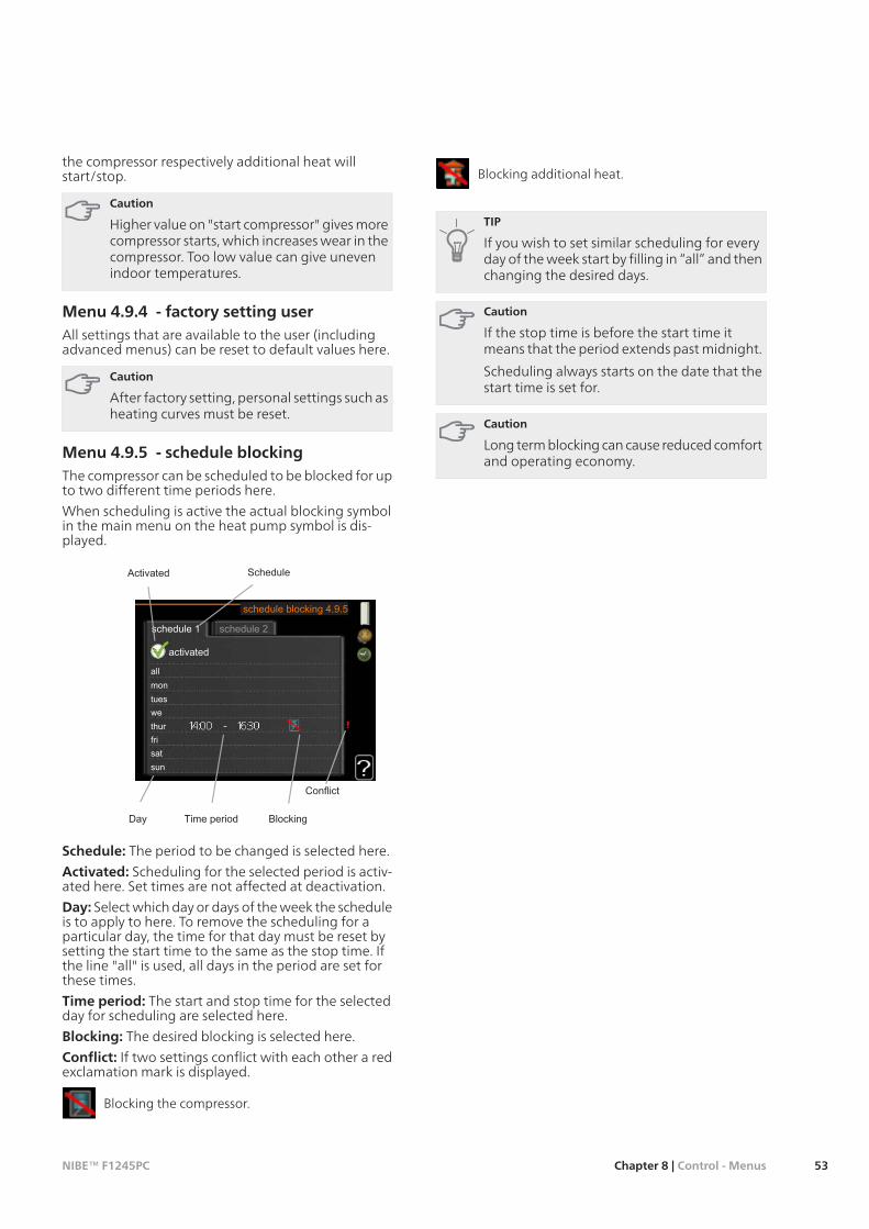
the compressor respectively additional heat willstart/stop.
Caution
Higher value on "start compressor" gives morecompressor starts, which increases wear in thecompressor. Too low value can give unevenindoor temperatures.
Menu 4.9.4 - factory setting userAll settings that are available to the user (includingadvanced menus) can be reset to default values here.
Caution
After factory setting, personal settings such asheating curves must be reset.
Menu 4.9.5 - schedule blockingThe compressor can be scheduled to be blocked for upto two different time periods here.
When scheduling is active the actual blocking symbolin the main menu on the heat pump symbol is dis-played.
Schedule: The period to be changed is selected here.
Activated: Scheduling for the selected period is activ-ated here. Set times are not affected at deactivation.
Day: Select which day or days of the week the scheduleis to apply to here. To remove the scheduling for aparticular day, the time for that day must be reset bysetting the start time to the same as the stop time. Ifthe line "all" is used, all days in the period are set forthese times.
Time period: The start and stop time for the selectedday for scheduling are selected here.
Blocking: The desired blocking is selected here.
Conflict: If two settings conflict with each other a redexclamation mark is displayed.
Blocking the compressor.
Blocking additional heat.
TIP
If you wish to set similar scheduling for everyday of the week start by filling in “all” and thenchanging the desired days.
Caution
If the stop time is before the start time itmeans that the period extends past midnight.
Scheduling always starts on the date that thestart time is set for.
Caution
Long term blocking can cause reduced comfortand operating economy.
53Chapter 8 | Control - MenusNIBE™ F1245PC

Menu 5 - SERVICE Overview
5.1.1 - hot water settings5.1 - operating settings5 - SERVICE
5.1.2 - max flow line temperat-ure
5.1.3 - max diff flow line temp.
5.1.4 - alarm actions
5.1.5 - fan sp. exhaust air *
5.1.7 - br pmp al set.
5.1.8 - operating mode brinepump
5.1.9 - brine pump speed
5.1.10 - op. mod heat medpump
5.1.11 - pump speed heatingmedium
5.1.12 - internal electrical addi-tion
5.1.14 - flow set. climate sys-tem
5.1.22 - heat pump testing
5.2.4 - accessories5.2 - system settings
5.3.1 - FLM *5.3 - accessory settings
5.3.2 - shunt controlled add.heat *
5.3.3 - extra climate system *
5.3.4 - solar heating *
5.3.6 - step controlled add.heat *
5.4 - soft in/outputs
5.5 - factory setting service
5.6 - forced control
5.7 - start guide
5.8 - quick start
5.9 - floor drying function
5.10 - change log
* Accessory needed.
Hold the Back button in for 7 seconds to access theService menu.
Sub-menus
Menu SERVICE has orange text and is intended forthe advanced user. This menu has several sub-menus.Status information for the relevant menu can be foundon the display to the right of the menus.
operating settings Operating settings for the heatpump.
system settings System settings for the heat pump,activating accessories etc.
accessory settings Operational settings for differentaccessories.
soft in/outputs Setting software controlled in andoutputs on the input circuit board (AA3).
factory setting service Total reset of all settings (includ-ing settings available to the user ) to default values.
forced control Forced control of the different compon-ents in the heat pump.
start guide Manual start of the start guide which isrun the first time the heat pump is started.
quick start Quick starting the compressor.
NIBE™ F1245PCChapter 8 | Control - Menus54
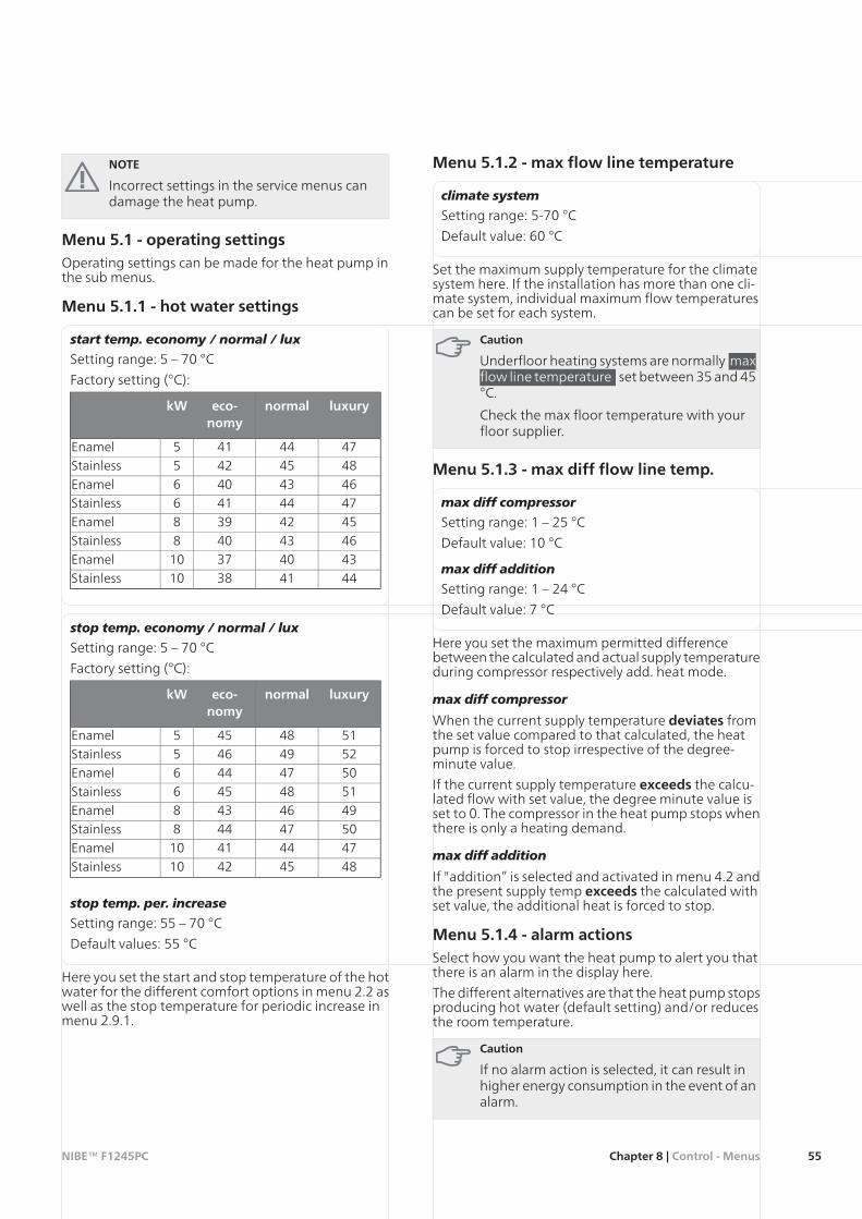
NOTE
Incorrect settings in the service menus candamage the heat pump.
Menu 5.1 - operating settingsOperating settings can be made for the heat pump inthe sub menus.
Menu 5.1.1 - hot water settings
start temp. economy / normal / lux
Setting range: 5 – 70 °C
Factory setting (°C):
luxurynormaleco-nomy
kW
4744415Enamel4845425Stainless4643406Enamel4744416Stainless4542398Enamel4643408Stainless43403710Enamel44413810Stainless
stop temp. economy / normal / lux
Setting range: 5 – 70 °C
Factory setting (°C):
luxurynormaleco-nomy
kW
5148455Enamel5249465Stainless5047446Enamel5148456Stainless4946438Enamel5047448Stainless47444110Enamel48454210Stainless
stop temp. per. increase
Setting range: 55 – 70 °C
Default values: 55 °C
Here you set the start and stop temperature of the hotwater for the different comfort options in menu 2.2 aswell as the stop temperature for periodic increase inmenu 2.9.1.
Menu 5.1.2 - max flow line temperature
climate system
Setting range: 5-70 °C
Default value: 60 °C
Set the maximum supply temperature for the climatesystem here. If the installation has more than one cli-mate system, individual maximum flow temperaturescan be set for each system.
Caution
Underfloor heating systems are normally maxflow line temperature set between 35 and 45°C.
Check the max floor temperature with yourfloor supplier.
Menu 5.1.3 - max diff flow line temp.
max diff compressor
Setting range: 1 – 25 °C
Default value: 10 °C
max diff addition
Setting range: 1 – 24 °C
Default value: 7 °C
Here you set the maximum permitted differencebetween the calculated and actual supply temperatureduring compressor respectively add. heat mode.
max diff compressor
When the current supply temperature deviates fromthe set value compared to that calculated, the heatpump is forced to stop irrespective of the degree-minute value.
If the current supply temperature exceeds the calcu-lated flow with set value, the degree minute value isset to 0. The compressor in the heat pump stops whenthere is only a heating demand.
max diff addition
If "addition” is selected and activated in menu 4.2 andthe present supply temp exceeds the calculated withset value, the additional heat is forced to stop.
Menu 5.1.4 - alarm actionsSelect how you want the heat pump to alert you thatthere is an alarm in the display here.
The different alternatives are that the heat pump stopsproducing hot water (default setting) and/or reducesthe room temperature.
Caution
If no alarm action is selected, it can result inhigher energy consumption in the event of analarm.
55Chapter 8 | Control - MenusNIBE™ F1245PC
Menu 5.1.5 - fan sp. exhaust air (accessoryis required)
normal and speed 1-4
Setting range: 0 – 100 %
Set the speed for the five different selectable speedsfor the fan here.
Caution
An incorrectly set ventilation flow can damagethe house and may also increase energy con-sumption.
Menu 5.1.7 - br pmp al set.
min. brine out
Setting range: -12 – 15 °C
Default value: -8 °C
max brine in
Setting range: 10 – 30 °C
Default value: 20 °C
min. brine out
Set the temperature at which the heat pump is to ac-tivate the alarm for low temperature in outgoing brine.
If "automatic reset" is selected, the alarm resets whenthe temperature has increased by 1 °C below the setvalue.
max brine in
Set the temperature at which the heat pump is to ac-tivate the alarm for high temperature in incomingbrine.
Select “alarm activated" to activate the alarm.
Menu 5.1.8 - operating mode brine pump
op. mode
Setting range: intermittent, continuous, 10 dayscontinuous
Default value: intermittent
Set the operating mode of the brine pump here.
intermittent: The brine pump starts approx. 20 secondsbefore and stops approx.20 seconds after the com-pressor.
continuous: Continuous operation.
10 days continuous: Continuous operation for 10days. Then the pump shifts to intermittent operation.
TIP
You can use “10 days continuous" at start-upto obtain continuous circulation during a start-up time in order to make it easier to bleed thesystem.
Menu 5.1.9 - brine pump speed
brine pump speed
Setting range: auto / manual
Default value: auto
Manual setting
Setting range: 1 - 100 %
Default values: 100 %
Manual setting, passive cooling
Setting range: 1 - 100 %
Default values: 75 %
This menu is not displayed if you have a F1245PC 10kW.
Set the speed of the brine pump here. Select "auto" ifthe speed of the brine pump is to be regulated auto-matically (factory setting) for optimal operation.
For manual operation of the brine pump deactivate"auto" and set the value to between 0 and 100%.
If there are accessories for cooling present or if the heatpump has a built-in function for cooling you can alsoset the brine pump speed during passive cooling oper-ation (the brine pump then runs in manual operation).
Menu 5.1.10 - op. mod heat med pump
op. mode
Setting range: auto, intermittent,
Default value: auto
Set the operating mode of the heating medium pumphere.
auto: The heating medium pump runs according tothe current operating mode for F1245PC.
intermittent: The heating medium pump starts 20seconds before and stops at the same time as thecompressor.
NIBE™ F1245PCChapter 8 | Control - Menus56

Menu 5.1.11 - pump speed heatingmedium
Operating status
Setting range: auto / manual
Default value: auto
Manual setting
Setting range: 1 - 100 %
Factory setting 5 kW: 35 %
Factory setting 6 kW: 40 %
Factory setting 8 kW Enamel: 55 %
Factory setting 8 kW Stainless: 40 %
Factory setting 10 kW Enamel: 70 %
Factory setting 10 kW Stainless: 55 %
max. allowed speed
Setting range: 50 - 100 %
Default values: 100 %
wait mode
Setting range: 1 - 100 %
Default values: 30 %
speed passive cooling
Setting range: 1 - 100 %
Default values: 70 %
Set the speed at which the heating medium pump isto operate in the present operating mode. Select "auto"if the speed of the heating medium pump is to beregulated automatically (factory setting) for optimaloperation.
If "auto" is activated for heating operation, you canalso make the setting "max. allowed speed" which re-stricts the heating medium pump and does not allowit to run at a higher speed than the set value.
For manual operation of the heating medium pumpdeactivate "auto" for the current operating mode andset the value to between 0 and 100% (the previouslyset value for "max. allowed speed" no longer applies).
"heating" means operating mode heating for theheating medium pump.
"wait mode" means heating or cooling operatingmodes for the heating medium pump but when theheat pump has neither a need for compressor opera-tion nor electrical addition and slows down.
"hot water" means operating mode hot water for theheating medium pump.
"pool" means operating mode pool heating for theheating medium pump.
"cooling" means operating mode cooling for theheating medium pump.
If there are accessories for cooling present or if the heatpump has a built-in function for cooling you can alsoset the heating medium pump speed during active re-spectively cooling operating modes (the heating medi-um pump then runs in manual operation).
Menu 5.1.12 - internal electrical addition
max connected el. add.
Setting range: 7 / 9
Factory setting: 7 kW
set max electrical add.
Setting range: 0 - 9 kW
Default values: 6 kW
fuse size
Setting range: 1 - 200 A
Default values: 16 A
Here you set the max. electrical output of the internalelectrical addition in F1245PC and the fuse size for theinstallation.
Here you can also check which current sensor is in-stalled on which incoming phase to the property (thisrequires current sensors to be installed, see page 24).This is achieved by marking "detect phase order" andpressing the OK button.
The results of these checks appear just below wherethe checks were activated.
Menu 5.1.14 - flow set. climate system
presettings
Setting range: radiator, floor heat., rad. + floor heat.,DOT °C
Default value: radiator
Setting range DOT: -40,0 - 20,0 °C
Factory setting DOT: -18,0 °C
own setting
Setting range dT at DOT: 0,0-25,0
Factory setting dT at DOT: 10,0
Setting range DOT: -40,0 - 20,0 °C
Factory setting DOT: -18,0 °C
The type of heating distribution system the heatingmedium pump (GP1) works towards is set here.
dT at DOT is the difference in degrees between flowand return temperatures at dimensioned outdoortemperature.
Menu 5.1.22 - heat pump testing
NOTE
This menu is intended for testing F1245PC ac-cording to different standards.
Use of this menu for other reasons may resultin your installation not functioning as inten-ded.
This menu contains several sub-menus, one for eachstandard.
57Chapter 8 | Control - MenusNIBE™ F1245PC

Menu 5.2 - system settingsMake different system settings for the heat pump here,e.g. which accessories are installed.
Menu 5.2.4 - accessoriesInform the heat pump which accessories are installedhere.
There are two ways of activating connected accessories.You can either mark the alternative in the list or usethe automatic function "search installed acc.".
search installed acc.
Mark “search installed acc." and press the OK buttonto automatically find connected accessories forF1245PC.
Caution
"level sensor" are not found automatically butmust be ticked off by hand.
NOTE
Only mark the option for ground water pumpif the accessory AXC 40 is to be used to controlthe circulation pump.
Menu 5.3 - accessory settingsThe operating settings for accessories that are installedand activated are made in the sub-menus for this.
Menu 5.3.1 - FLM
time between defrosts
Setting range: 1 – 30 h
Default value: 10 h
months btwn filter alarms
Setting range: 1 – 12
Default value: 3
continuouspumpop.: Select for continuous operationof the circulation pump in the exhaust air module.
time between defrosts: Set the minimum time thatmust pass between defrostings of the heat exchangerin the exhaust air module.
When the exhaust air module is in operation the heatexchanger is cooled so that ice builds up on it. Whentoo much ice builds up the heat transfer capacity ofthe heat exchanger is reduced and defrosting is re-quired. Defrosting warms up the heat exchanger sothat the ice melts and runs off via the condensationhose.
months btwn filter alarms: Set how many monthsshould pass before the heat pump informs that it istime to clean the filter in the exhaust air module.
Clean the exhaust air module's air filter regularly, howoften depends on the amount of dust in the ventilationair.
activate cooling: Activate cooling via the exhaust airmodule here. When the function has been activated,the cooling settings are displayed in the menu system.
Menu 5.3.2 - shunt controlled add. heat
start addition
Setting range: -2000 – -30 GM
Default values: -400 GM
minimum running time
Setting range: 0 – 48 h
Default value: 12 h
min temp.
Setting range: 5 – 90 °C
Default value: 55 °C
mixing valve amplifier
Setting range: 0.1 –10.0
Default value: 1.0
mixing valve step delay
Setting range: 10 – 300 s
Default values: 30 s
Set when the addition is to start, the minimum run timeand the minimum temperature for external additionwith shunt here. External addition with shunt is thenfor example wood/oil/gas/pellet boiler.
For the shunt you can set shunt amplification and shuntwaiting time.
See the accessory installation instructions for functiondescription.
Menu 5.3.3 - extra climate system
mixing valve amplifier
Setting range: 0.1 –10.0
Default value: 1.0
mixing valve step delay
Setting range: 10 – 300 s
Default values: 30 s
Set the shunt amplification and shunt waiting time forthe different extra climate systems that are installed.
See the accessory installation instructions for functiondescription.
NIBE™ F1245PCChapter 8 | Control - Menus58

Menu 5.3.4 - solar heating
start delta-T
Setting range: 1 - 40 °C
Default value: 8 °C
stop delta-T
Setting range: 0 - 40 °C
Default value: 4 °C
max. tank temperature
Setting range: 5 - 110 °C
Default value: 95 °C
max. solar collector temp.
Setting range: 80 - 200 °C
Default value: 125 °C
anti-freeze temperature
Setting range: -20 - +20 °C
Default value: 2 °C
start solar collector cooling
Setting range: 80 - 200 °C
Default value: 110 °C
passive recharging - activation temperature
Setting range: 50 - 125 °C
Default value: 110 °C
passive recharging - deactivation temperature
Setting range: 30 - 90 °C
Default value: 50 °C
active recharging - activating dT
Setting range: 8 - 60 °C
Default value: 40 °C
active recharging - deactivating dT
Setting range: 4 - 50 °C
Default value: 20 °C
start delta-T, stop delta-T: Here you can set the tem-perature difference between solar panel and solar tankat which the circulation pump is to start and stop.
max. tank temperature, max. solar collector temp.:Here you can set the maximum temperatures in tankrespectively solar panel at which the circulation pumpis to stop. This is to protect against excess temperaturesin the solar tank.
If the unit has an anti-freeze function, solar panelcooling and/or passive/active recharging you can activ-ate them here. When the function has been activated,you can make settings for them. "solar panel cooling","passive recharging" and "active recharging" cannotbe combined, only one function can be activated.
freeze protection
anti-freeze temperature: Here you can set the temper-ature in the solar panel at which the circulation pumpis to start to prevent freezing.
solar panel cooling
start solar collector cooling: If the temperature in thesolar panel is greater than this setting at the same timethat the temperature in the solar tank is greater thanthe set maximum temperature, the external functionfor cooling is activated.
passive recharging
activation temperature: If the temperature in thesolar panel is greater than this setting, the functionactivates. The function is blocked for an hour if thetemperature of the brine in the heat pump (BT10) ishigher than the set value for "max brine in" in menu5.1.7
deactivation temperature: If the temperature in thesolar panel is less than this setting, the function deac-tivates.
active recharging
activating dT: If the difference between the temperat-ure in the solar panel (BT53) and the temperature ofthe brine in the heat pump (BT10) is greater than thissetting the function is activated. The function is blockedfor an hour if the temperature of the brine in the heatpump (BT10) is higher than the set value for "max brinein" in menu 5.1.7
deactivatingdT: If the difference between the temper-ature in the solar panel (BT53) and the temperature ofthe brine in the heat pump (BT10) is less than this set-ting the function is deactivated.
Menu 5.3.6 - step controlled add. heat
start addition
Setting range: -2000 – -30 GM
Default values: -400 GM
diff. between additional steps
Setting range: 0 – 1000 GM
Default values: 100 GM
max step
Setting range(binary stepping deactivated): 0 – 3
Setting range(binary stepping activated): 0 – 7
Default value: 3
Make settings for step controlled addition here. Stepcontrolled addition is for example an external electricboiler.
It is possible, for example, to select when the additionalheat is to start, to set the maximum number of permit-ted steps and whether binary stepping is to be used.
See the accessory installation instructions for functiondescription.
59Chapter 8 | Control - MenusNIBE™ F1245PC

Menu 5.4 - soft in/outputsHere you can select which in/output on the input circuitboard (AA3) the external contact function (page 24)is to be connected to.
Selectable inputs on terminal block AUX1-5 (AA3-X6:9-18) and output AA3-X7 (on the input circuit board).
Menu 5.5 - factory setting serviceAll settings can be reset (including settings availableto the user) to default values here.
NOTE
When resetting, the start guide is displayedthe next time the heat pump is restarted.
Menu 5.6 - forced controlYou can force control the different components in theheat pump and any connected accessories here.
Menu 5.7 - start guideWhen the heat pump is started for the first time thestart guide starts automatically. Start it manually here.
See page 29 for more information about the startguide.
Menu 5.8 - quick startIt is possible to start the compressor from here.
Caution
There must be a heating or hot water demandto start the compressor.
Caution
Do not quick start the compressor too manytimes in succession over a short period of timeas this may damage the compressor and itsancillary equipment.
Menu 5.9 - floor drying function
length of period 1 - 3, 5-7
Setting range: 0 - 30 days
Default value: 2 days
temp. period 1 - 3, 5-7
Setting range: 15 - 70 °C
Default value:20 °Ctemp. period 130 °Ctemp. period 240 °Ctemp. period 340 °Ctemp. period 530 °Ctemp. period 620 °Ctemp. period 7
length of period 4
Setting range: 0 - 30 days
Default value: 3 days
temp. period 4
Setting range: 15 - 70 °C
Default value: 45 °C
Set the function for under floor drying here.
You can set up to seven period times with differentcalculated flow temperatures. If less than seven periodsare to be used, set the remaining period times to 0days.
Mark the active window to activate the under floordrying function. A counter at the bottom shows thenumber of days the function has been active. Thefunction counts degree minutes as during normalheating operation but for the flow temperatures thatare set for the respective period.
NOTE
During floor drying the heating medium pumpin 100% runs regardless of the setting in menu5.1.10.
TIP
If operating mode "add. heat only" is to beused, select it in menu 4.2.
For a more even flow temperature the additioncan be started earlier by setting "start for addi-tion" in menus 4.9.2 to -80. When set underfloor drying periods have stopped, reset themenus 4.2 and 4.9.2 as per previous settings.
NIBE™ F1245PCChapter 8 | Control - Menus60

Menu 5.10 - change logRead off any previous changes to the control systemhere.
The date, time and ID no. (unique to certain settings)and the new set value is shown for every change.
NOTE
The change log is saved at restart and remainsunchanged after factory setting.
61Chapter 8 | Control - MenusNIBE™ F1245PC

Service actionsNOTE
Servicing should only be carried out by personswith the necessary expertise.
When replacing components on F1245PC onlyreplacement parts from NIBE may be used.
Emergency mode
NOTE
Switch (SF1) must not be moved to "" or " "until F1245PC has been filled with water.Otherwise the temperature limiter, thermostat,compressor and the immersion heater can bedamaged.
Emergency mode is used in event of operational inter-ference and in conjunction with service. Hot water isnot produced in emergency mode.
Activate emergency mode by setting the switch (SF1)to " " (press the button on the switch and move it tothe right). This means that:
The status lamp illuminates yellow.The display is not lit and the control computer is notconnected.The temperature at the immersion heater is con-trolled by the thermostat (FD1-BT30). It can be seteither to 35 or 45 °C.The compressor and the brine system are off andonly the heating medium pump and the electricaladdition are active. The addition power in emergencymode is set in the immersion heater card (AA1). Seepage 23 for instructions.
LEK
LEK
F1245
QM34
QM32
SF1
QM33
XL1
XL6 XL7
XL4 XL3 XL2
FD1-BT30
QM31
Draining the water heaterThe siphon principle is used to empty the hot waterheater. This can be done either via the drain valve onthe incoming cold water pipe or by inserting a hoseinto the cold water connection.
Draining the climate systemIn order to carry out service on the climate system, itmay be easier to drain the system first. This can be donein different ways depending on what needs doing:
NIBE™ F1245PCChapter 9 | Service62
9 Service

NOTE
There may be some hot water when drainingthe heating medium side/climate system.There is a risk of scalding.
Draining the heating medium side in the coolingmodule
If, for example, the heating medium pump requiresreplacing or the cooling module requires servicing,drain the heating medium side as follows:1. Close the shut-off valves to heating medium side
(QM31) and (QM32).2. Connect a hose to the bleed valve (QM1) and open
the valve. Some liquid will run out.3. Air must get into the system for the remaining li-
quid to run out. Do this by slightly slackening offthe connection at the shut-off valve (QM32) thatjoins the heat pump to the cooling module.
When the heating medium side is drained, the requiredservice can be performed and/or replacement of anycomponents carried out.
Draining the heating medium system in the heatpump
If the heat pump requires servicing, drain the heatingmedium side as follows:1. Close the shut-off valves outside the heat pump
for the heating medium side (return and flow line).2. Connect a hose to the bleed valve (QM1) and open
the valve. Some liquid will run out.3. Air must get into the system for the remaining li-
quid to run out. Do this by slightly slackening offthe connection at the shut-off valve that joins theclimate system and the heat pump at the connec-tion (XL2).
When the heating medium side is empty the requisiteservice can be carried out.
Draining the entire climate system
If the entire climate system requires draining, do thisas follows:1. Connect a hose to the bleed valve (QM1) and open
the valve. Some liquid will run out.2. Air must get into the system for the remaining li-
quid to run out. This is done by unscrewing thebleed screw on the highest radiator in the house.
When the climate system is empty the requisite servicecan be carried out.
Emptying the brine systemIn order to service the brine system it may be easier todrain the system first. This can be done in differentways depending on what needs doing:
Draining the brine system in the cooling module
If, for example, the brine pump requires replacing orthe cooling module requires servicing, drain the brinesystem by:
1. Close the shut-off valves to brine system (QM33)and (QM34).
2. Connect a hose to the drain valve (QM2), place theother opening of the hose in a container and openthe valve. A small amount of brine will flow intothe container.
3. Air must get into the system for the remainingbrine to run out. Do this by slightly slackening offthe connection at the shut-off valve (QM33) thatjoins the heat pump with the cooling module.
When the brine side is empty the requisite service canbe carried out.
Draining the brine system in the heat pump
If the heat pump requires servicing, drain the brinesystem by:1. Close the shut-off valve outside the heat pump for
the brine system.2. Connect a hose to the drain valve (QM2), place the
other opening of the hose in a container and openthe valve. A small amount of brine will flow intothe container.
3. Air must get into the system for the remainingbrine to run out. Do this by slightly slackening offthe connection at the shut-off valve that joins thebrine side and the heat pump at the connection(XL7).
When the brine side is empty the requisite service canbe carried out.
Helping the circulation pump to start (GP1)
1. Shut off F1245PC by setting the switch (SF1) to" ".
2. Open the service cover.3. Remove the cover for the cooling module.4. Loosen the venting screw (QM5) with a screwdriver.
Hold a cloth around the screwdriver blade as asmall amount of water may run out.
5. Insert a screwdriver and turn the pump motoraround.
6. Screw in the venting screw (QM5).7. Start F1245PC by setting the switch (SF1) to "" and
check whether the circulation pump works.
It is usually easier to start the circulation pump withF1245PC running, switch (SF1) set to " ". Helping thecirculation pump to start is performed with F1245PCrunning, be prepared for the screwdriver to jerk whenthe pump starts.
63Chapter 9 | ServiceNIBE™ F1245PC

Luftningsskruv
The image shows an example of what a circulation pump canlook like.
Temperature sensor data
Voltage (VDC)Resistance(kOhm)
Temperature(°C)
3.256351.0-403.240251.6-353.218182.5-303.189133.8-253.15099.22-203.10574.32-153.04756.20-102.97642.89-52.88933.0202.78925.6152.67320.02102.54115.77152.39912.51202.24510.00252.0838.045301.9166.514351.7525.306401.5874.348451.4263.583501.2782.968551.1362.467601.0072.068650.8911.739700.7851.469750.6911.246800.6071.061850.5330.908900.4690.779950.4140.672100
Pulling out the cooling moduleThe cooling module can be pulled out for service andtransport.
Caution
The cooling module is easy to remove if it isdrained first (see page 62).
Weight of the cooling module
Weight (kg)Type (kW)
11851236133813810
NOTE
Shut off the heat pump and turn off the cur-rent on the safety breaker.
Caution
Remove the front cover according to the de-scription on page 6.
Close the shut-off valves (QM31), (QM32), (QM33)and (QM34).
1
Drain the compressor module according to the in-structions on page 62
F1245
QM33
QM32QM34
QM31
Pull off the lock catches.2
LEK
3
2
QM31
Disconnect the pipe connection at the shut-offvalve (QM31).
3
NIBE™ F1245PCChapter 9 | Service64
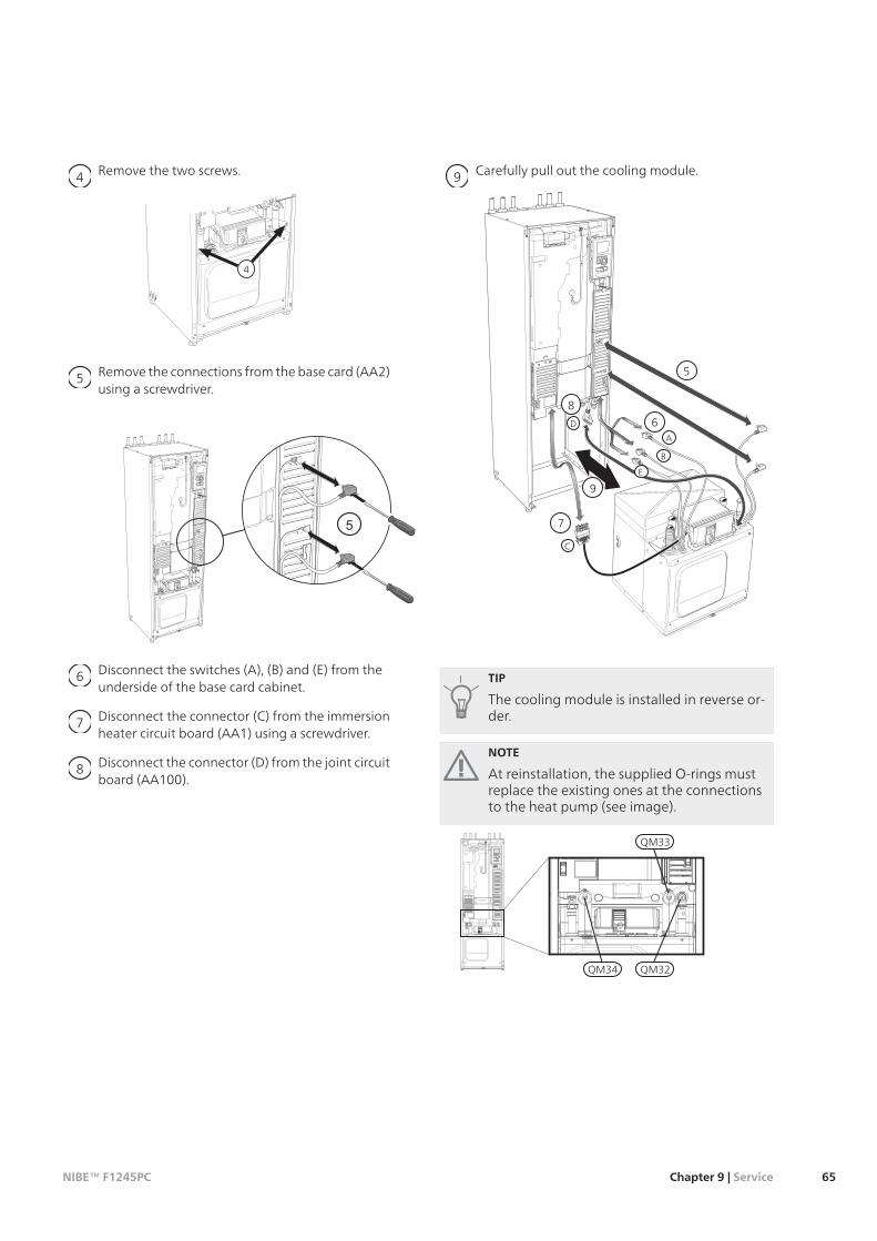
Remove the two screws.4
LEK
4
Remove the connections from the base card (AA2)using a screwdriver.
5
LEK
Disconnect the switches (A), (B) and (E) from theunderside of the base card cabinet.
6
Disconnect the connector (C) from the immersionheater circuit board (AA1) using a screwdriver.
7
Disconnect the connector (D) from the joint circuitboard (AA100).
8
Carefully pull out the cooling module.9
LEK
6A
B
7
C
D
8
9
5
E
TIP
The cooling module is installed in reverse or-der.
NOTE
At reinstallation, the supplied O-rings mustreplace the existing ones at the connectionsto the heat pump (see image).
F1245
QM33
QM32QM34
65Chapter 9 | ServiceNIBE™ F1245PC

USB service outlet
LEK
F1245PC is equipped with a USB socket in the displayunit. This USB socket can be used to connect a USBmemory to update the software, save logged informa-tion and handle the settings in F1245PC.
When a USB memory is connected a new menu (menu7) appears in the display.
Menu 7.1 - update firmware
This allows you to update the software in F1245PC.
NOTE
For the following functions to work the USBmemory must contain files with software forF1245PC from NIBE.
The fact box at the top of the display shows information(always in English) of the most probable update thatthe update software has selected form the USBmemory.
This information states which product the software isintended for, the software version and general inform-ation about them. If you wish to select another file thanthe one selected, the correct file can be selected by"choose another file".
start updating
Select “start updating" if you want to start the update.You are asked whether you really want to update thesoftware. Respond "yes" to continue or "no" to undo.
If you responded"yes" to the previous question theupdate starts and you can now follow the progress ofthe update on the display. When the update is com-plete F1245PC restarts.
NOTE
A software update does not reset the menusettings in F1245PC.
NOTE
If the update is interrupted before it is com-plete (for example power cut etc.) the softwarecan be reset to the previous version if the OKbutton is held in during start up until the greenlamp starts to illuminate (takes about 10seconds).
NIBE™ F1245PCChapter 9 | Service66

choose another file
Select “choose another file" if you do not want to usethe suggested software. When you scroll through thefiles, information about the marked software is shownin a fact box just as before. When you have selected afile with the OK button you will return to the previouspage (menu 7.1) where you can choose to start theupdate.
Menu 7.2 - logging
Setting range: 1 s – 60 min
Default setting range: 5 s
Set whether the present measurement values fromF1245PC are to be saved in a log on the USB memory.
Log for longer periods1. Set the desired interval between loggings.2. Tick “activated".3. The present values from F1245PC are saved in a
file in the USB memory at the set interval until“activated" is unticked.
Caution
Untick "activated" before removing the USBmemory.
Menu 7.3 - manage settings
Here you can manage (save as or retrieve from) all themenu settings (user and service menus) in F1245PCwith a USB memory.
Via "save settings" you save the menu settings to theUSB memory in order to restore them later or to copythe settings to another F1245PC.
NOTE
When you save the menu settings to the USBmemory you replace any previously saved set-tings on the USB memory.
Via "recover settings" you reset all menu settings fromthe USB memory.
NOTE
Reset of the menu settings from the USBmemory cannot be undone.
67Chapter 9 | ServiceNIBE™ F1245PC

In most cases, the heat pump notes operational inter-ference (operational interference can lead to disturb-ance in comfort) and indicates this with alarms andshows action instructions in the display.
Info-menuAll the heat pump measurement values are gatheredunder menu 3.1 in the heat pump menu system.Looking through the values in this menu can oftensimplify finding the fault source. See page 48 for moreinformation about menu 3.1.
Manage alarm
In the event of an alarm, some kind of malfunction hasoccurred, which is indicated by the status lamp chan-ging from green continuously to red continuously. Inaddition, an alarm bell appears in the informationwindow.
AlarmIn the event of an alarm with a red status lamp a mal-function has occurred that the heat pump cannotremedy itself. In the display, by turning the control knoband pressing the OK button, you can see the type ofalarm it is and reset it. You can also choose to set theheat pump to aid mode.
info / action Here you can read what the alarm meansand receive tips on what you can do to correct theproblem that caused the alarm.
reset alarm In most cases it is enough to select "resetalarm" to correct the problem that caused the alarm.If a green light illuminates after selecting "reset alarm"the alarm has been remedied. If a red light is still visibleand a menu called ”alarm” is visible in the display, theproblem that caused the alarm remains. If the alarmdisappears and then returns, see the troubleshootingsection (page 68).
aid mode ”aid mode” is a type of emergency mode.This means that the heat pump produces heat and/orhot water despite there being some kind of problem.This can mean that the heat pump's compressor is notrunning. In this case the immersion heater producesheat and/or hot water.
Caution
Selecting "aid mode” is not the same as correct-ing the problem that caused the alarm. Thestatus lamp will therefore continue to be red.
TroubleshootingIf the operational interference is not shown in the dis-play the following tips can be used:
Basic actionsStart by checking the following possible fault sources:
The switch's (SF1) position.Group and main fuses of the accommodation.The property's earth circuit breaker.The heat pump's miniature circuit breaker (FA1).The heat pump's temperature limiter (FD1).Correctly set load monitor (if installed).
Low hot water temperature or a lack of hotwater
Closed or choked filling valve for the hot waterheater.
Open the valve.Heat pump in incorrect operating mode.
If mode "manual" is selected, select "addition".Large hot water consumption.
Wait until the hot water has heated up. Temporar-ily increased hot water capacity (temporary lux)can be activated in menu 2.1.
Too low hot water setting.Enter menu 2.2 and select a higher comfort mode.
Too low or no operating prioritisation of hot water.Enter menu 4.9.1 and increase the time for whenhot water is to be prioritised.
Low room temperatureClosed thermostats in several rooms.
Set the thermostats to max in as many rooms aspossible. Adjust the room temperature via menu1.1 instead of choking the thermostats.
Heat pump in incorrect operating mode.Enter menu 4.2. If mode "auto" is selected, selecta higher value on "stop heating“ in menu 4.9.2.If mode "manual" is selected, select "heating". Ifthis is not enough, select "addition".
Too low set value on the automatic heating control.Enter menu 1.1 "temperature" and adjust the offsetof the heating curve. If the room temperature isonly low in cold weather the curve slope in menu1.9.1 "heating curve" needs adjusting up.
Too low or no operating prioritisation of heat.Enter menu 4.9.1 and increase the time for whenheating is to be prioritised.
"Holiday mode" activated in menu 4.7.Enter menu 4.7 and select “Off”.
External switch for changing the room heating activ-ated.
Check any external switches.Circulation pump(s) (GP1 and/or GP2) stopped.
See section "Helping the circulation pump to start"on page 63.
NIBE™ F1245PCChapter 10 | Disturbances in comfort68
10 Disturbances in comfort
Air in the climate system.Vent the climate system (see page 28).
Closed valves (QM20), (QM32)to the climate system.Open the valves.
High room temperatureToo high set value on the automatic heating control.
Enter menu 1.1 (temperature) and adjust the heatcurve offset downwards. If the room temperatureis only high in cold weather the curve slope in menu1.9.1 (heating curve) needs to be adjusted down.
External switch for changing the room heating activ-ated.
Check any external switches.
Uneven room temperature.Incorrectly set heating curve.
Adjust the heating curve in menu 1.9.1.Too high set value on "dT at DOT"..
Enter menu 5.1.14 (flow set. climate system) andreduce the value of "dT at DOT".
Uneven flow over the radiators.Adjust the flow distribution between the radiators.
Low system pressureNot enough water in the climate system.
Top up the water in the climate system (see page28).
Low or a lack of ventilationThis part of the fault-tracing chapter only applies if theNIBE FLM accessory is installed.
The ventilation is not adjusted.Order/implement ventilation adjustment.
Filter (HQ10) blocked.Clean or replace the filter.
Exhaust air device blocked or throttled down toomuch.
Check and clean the exhaust air devices.Fan speed in reduced mode.
Enter menu 1.2 and select “normal".External switch for changing the fan speed activated.
Check any external switches.
High or distracting ventilationThis part of the fault-tracing chapter only applies if theNIBE FLM accessory is installed.
The ventilation is not adjusted.Order/implement ventilation adjustment.
Fan speed in forced mode.Enter menu 1.2 and select “normal".
External switch for changing the fan speed activated.Check any external switches.
Filter blocked.Clean or replace the filter.
The compressor does not startThere is no heating requirement.
The heat pump does not call on heating nor hotwater.
Temperature conditions tripped.Wait until the temperature condition has been re-set.
Minimum time between compressor starts has notbeen reached.
Wait 30 minutes and check if the compressor hasstarted.
Alarm tripped.Follow the display instructions.
Whining noise in the radiatorsClosed thermostats in the rooms and incorrectly setheating curve.
Set the thermostats to max in as many rooms aspossible. Adjust the heating curve via menu 1.1instead of choking the thermostats.
Circulation pump speed set too high.Enter menu 5.1.11 (pump speed heating medium)and reduce the speed of the circulation pump.
Uneven flow over the radiators.Adjust the flow distribution between the radiators.
Gurgling soundThis part of the fault-tracing chapter only applies if theNIBE FLM accessory is installed.
Not enough water in the water seal.Refill the water seal with water.
Choked water seal.Check and adjust the condensation water hose.
69Chapter 10 | Disturbances in comfortNIBE™ F1245PC
Accessory card AXC 40An accessory card is required if step controlled addition(e.g. external electric boiler) or if shunt controlled addi-tion (e.g. wood/oil/gas/pellet boiler) is to be connectedto F1245PC.
An accessory card is also required if the ground waterpump or external circulation pump is connected toF1245PC at the same time that the buzzer alarm is ac-tivated.
Part no. 067 060
Active/Passive cooling (4-pipe) ACS 45Part no. 067 195
Active/Passive cooling HPAC 40Part no. 067 076
Auxiliary relay HR 10Part no. 067 309
Base extension EF 45Part no. 067 152
Buffer vessel UKV
UKV 102
Part no. 080 310
UKV 200
Part no. 080 300
Communications module MODBUS 40MODBUS 40 enables F1245PC to be controlled andmonitored using a DUC (computer sub-center) in thebuilding. Communication occurs using MODBUS-RTU.
Part no. 067 144
Communications module SMS 40SMS 40 enables operation and monitoring of F1245PC,via a GSM module, using a mobile phone via SMSmessages. If the mobile telephone also has the Androidoperating system the mobile application ”NIBE MobileApp” can be used.
Part no. 067 073
Exhaust air module FLMFLM is an exhaust air module specially designed tocombine recovery of mechanical exhaust air with anenergy collector in rock.
Bracket pack FLM
Part no. 067 083
FLM
Part no. 067 011
External electrical addition ELKThese accessories require accessories card AXC 40 (stepcontrolled addition).
ELK 5
Immersion heater
5 kW, 1 x 230 V
Part no. 069 025
ELK 8
Immersion heater
8 kW, 1 x 230 V
Part no. 069 026
ELK 15
Immersion heater
15 kW, 3 x 400 V
Part no. 069 022
ELK 26
Immersion heater
26 kW, 3 x 400 V
Part no. 067 074
ELK 42
Immersion heater
42 kW, 3 x 400 V
Part no. 067 075
ELK 213
Part no. 069 500
Extra shunt group ECS 40/ECS 41This accessory is used when F1245PC is installed inhouses with two or more different climate systems thatrequire different supply temperatures.
Part no. 067 287ECS 40 (Max. 80 m²)Part no. 067 288ECS 41 (Min. 80 m²)
Filling valve kit KB 25/32Filling valve kit for filling brine in the collector hose forrock heat pumps. Includes dirt filter and insulation.
KB 32 (max 30 kW)
Part no. 089 971
KB 25 (max 12 kW)
Part no. 089 368
Level monitor NV 10Part no. 089 315
Passive coolingPCM 42
Part no. 067 078
PCM 40
Part no. 067 077
Pool heating POOL 40POOL 40 is an accessory that enables pool heating withF1245PC.
Part no. 067 062
NIBE™ F1245PCChapter 11 | Accessories70
11 Accessories

Room unit RMU 40RMU 40 means that control and monitoring of the heatpump can be carried out in a different part of the ac-commodation to where F1245PC is located.
Part no. 067 064
Water heater/Accumulator tank
AHPS
Accumulator tank with a solar coil (copper) and acombined pre-heating and post-heating coil (stainlesssteel) for hot water production.
Part no. 056 283
AHP
Volume expansion tank that is primarily used for ex-panding the volume with an AHPS.
Part no. 056 284
71Chapter 11 | AccessoriesNIBE™ F1245PC

Dimensions and setting-out coordinates
62
0
600
560 440
70
17
75
65
0*
25
-50
25
50
130
210
390
470
525
65
0*
* This dimension applies at 90° angle on the brine pipes (side connection). The dimension can vary approx. ±100mm in height as the brine pipes partially consist of flexible pipes.
NIBE™ F1245PCChapter 12 | Technical data72
12 Technical data

Technical specifications IP 21
1x230V
51x230V
Output data at nom flow Refers to performance of heat pump excl. circulation pumps
0/354.89kWRated output3.83kWCooling output1.06kWElectrical output4.62-COP
0/503.79kWRated output2.61kWCooling output1.18kWElectrical output3.20-COP
Output data according to EN 14511:20110/35
4.65kWRated output1.08kWElectrical output4.30-COPEN14511
0/453.98kWRated output1.17kWElectrical output3.40-COPEN14511
1/2/3/4/5/6/7kWAdditional powerElectrical data
230V 50 HzRated voltage9.5ArmsMax operating current, compressor
(Including Control system and Circulation pumps)23ArmsStarting current
-ohmMax permitted impedance at connection point 1)
18(20)ArmsMax operating current heat pump incl. 1 – 2 kW immersion heater
(Recommended fuse rating)27(32)ArmsMax operating current heat pump incl. 3 – 4 kW immersion heater
(Recommended fuse rating)36(40)ArmsMax operating current heat pump incl. 5 – 6 kW immersion heater
(Recommended fuse rating)40(40)ArmsMax operating current heat pump including 7 kW immersion heater
(Recommended fuse rating)30 – 87WOutput, Brine pump7 – 63WOutput, Heating medium pumpIP 21IP class
Refrigerant circuitR407CType of refrigerant
1.2kgVolume2.9 (29 bar)MPaCut-out value pressostat HP-0.7 (-7 bar)MPaDifference pressostat HP
0.15 (1.5 bar)MPaCut-out value pressostat LP0.15 (1.5 bar)MPaDifference pressostat LP
73Chapter 12 | Technical dataNIBE™ F1245PC

51x230V
Brine circuitlow energyEnergy class Brine pump0.3 (3 bar)MPaMax system pressure brine
0.19l/sMin flow0.23l/sNominal flow
63/62kPaMax external avail. press at nom flow, heating/cooling operationsee diagram°CMax/Min incoming Brine temp
-12°CMin. outgoing brine temp.Heating medium circuit
low energyEnergy class circ-pump0.4 (4 bar)MPaMax system pressure heating medium
0.08l/sMin flow0.10l/sNominal flow49kPaMax external avail. press at nom flow
see diagram°CMax/Min heating medium temp37dB(A)Noise output (LWA) according to EN 12102 at 0/35
21.5dB(A)Sound pressure level (LPA) calculated values according to EN ISO 11203 at 0/35 and a distance
of 1 m
Pipe connections28mmBrine ext diam. CU pipe22mmHeating medium ext diam. CU pipes22mmHot water connection external diam22mmCold water connection external diam
3x400V
108653x400V
Output data at nom flow Refers to performance of heat pump excl. circulation pumps
0/3510.068.196.484.89kWRated output8.116.575.173.83kWCooling output1.951.621.311.06kWElectrical output5.155.054.944.62-COP
0/508.466.735.153.79kWRated output6.144.813.612.61kWCooling output2.321.921.531.18kWElectrical output3.643.513.363.20-COP
Output data according to EN 14511:20110/35
9.667.676.074.65kWRated output2.011.641.321.08kWElectrical output4.814.684.594.30-COPEN14511
0/458.556.705.193.98kWRated output2.271.831.461.17kWElectrical output3.773.673.563.40-COPEN14511
1/2/3/4/5/6/7 (switchable to 2/4/6/9)kWAdditional powerElectrical data
400V 3NAC 50 HzRated voltage
NIBE™ F1245PCChapter 12 | Technical data74

108653x400V
6.9(16)6.6(16)4.6(16)9.5(1-phase)(16)
ArmsMax operating current, compressor
Including Control system, Circulation pumps and 0 kW immersion heater
(Recommended fuse rating)23231823ArmsStarting current
----ohmMax permitted impedance at connection point 1)
15(16)15(16)13(16)18(20)ArmsMax operating current heat pump incl. 1 – 2 kW immersion heater
(Recommended fuse rating)15(16)15(16)13(16)18(20)ArmsMax operating current heat pump incl. 3 – 4 kW immersion heater
(Recommended fuse rating)15(16)15(16)13(16)18(20)ArmsMax operating current heat pump incl. 5 – 6 kW immersion heater
(Recommended fuse rating)21(25)21(25)19(20)18(20)ArmsMax operating current heat pump including 7 kW immersion heater,
connected upon delivery
(Recommended fuse rating)22(25)22(25)19(20)24(25)ArmsMax operating current heat pump including 9 kW immersion heater, re-
quires switching
(Recommended fuse rating)35 – 18530 – 8730 – 8730 – 87WOutput, Brine pump
7 – 637 – 637 – 637 – 63WOutput, Heating medium pumpIP 21IP class
Refrigerant circuitR407CType of refrigerant
2.11.81.51.2kgVolume2.9 (29 bar)MPaCut-out value pressostat HP-0.7 (-7 bar)MPaDifference pressostat HP
0.15 (1.5 bar)MPaCut-out value pressostat LP0.15 (1.5 bar)MPaDifference pressostat LP
Brine circuitlow energyEnergy class Brine pump0.3 (3 bar)MPaMax system pressure brine
0.400.330.250.19l/sMin flow0.510.420.300.23l/sNominal flow
84/6947/3859/5563/62kPaMax external avail. press at nom flow, heating/cooling operationsee diagram°CMax/Min incoming Brine temp
-10°CMin. outgoing brine temp.Heating medium circuit
low energyEnergy class circ-pump0.4 (4 bar)MPaMax system pressure heating medium
0.160.130.100.08l/sMin flow0.220.180.130.10l/sNominal flow43474649kPaMax external avail. press at nom flow
see diagram°CMax/Min heating medium temp43434237dB(A)Noise output (LWA) according to EN 12102 at 0/35
28282721.5dB(A)Sound pressure level (LPA) calculated values according to EN ISO 11203 at 0/35 and
a distance of 1 m
Pipe connections28mmBrine ext diam. CU pipe22mmHeating medium ext diam. CU pipes22mmHot water connection external diam
75Chapter 12 | Technical dataNIBE™ F1245PC

108653x400V
22mmCold water connection external diam
Miscellaneous
10865Miscellaneous
Water heater180lVolume water heater
1.0 (10 bar)MPaMax pressure in water heaterCapacity hot water heating (comfort mode Normal) According to EN16147
235235240240Amount of hot water (40 °C)2.82.82.82.7COPDHW (tap profile XL)
Dimensions and weight600mmWidth620mmDepth
1800mmHeight1950mmRequired ceiling height 2)
280275265260kgWeight complete heat pump138133123118kgWeight only cooling module
---065 154Part number, 1x230V, Stainless065 131065 130065 129065 128Part number, 3x400V, Stainless065 123065 122065 121065 120Part number, 3x400V, Enamel (for Germany, Switzerland and Austria only)
1)Max. permitted impedance in the mains connected point inaccordance with EN 61000-3-11. Start currents can cause shortvoltage dips that could affect other equipment in unfavourableconditions. If the impedance in the mains connection point ishigher than that stated it is possible that interference will occur.If the impedance in the mains connection point is higher thanthat stated check with the power supplier before purchasing theequipment.2)With feet dismantled the height is approx. 1930 mm.
Working range heat pump, compressor op-erationThe compressor provides a flow temperature up to 65°C, the remainder (up to 70 °C) is obtained using theadditional heat.
0
10
20
30
40
50
60
70
-15 -10 -5 0 5 10 15 20 25 30 35
°Cp
°C
Temperature
Incoming brine tempFlow pipe
Return pipe
Diagram, passive cooling outputSystem temperature: 18 °C/23 °C, nominal brine flow
0,0
2,0
4,0
6,0
8,0
10,0
12,0
14,0
5 6 7 8 9 10 11 12 13 14 15
8 kW10 kW
6 kW5 kW
°C
kW
NIBE™ F1245PCChapter 12 | Technical data76

Item register
AAccessibility, electrical connection, 19Accessories, 70Alarm, 68Assembly, 5
BBack button, 34Brine side, 14
CCable lock, 19Commissioning and adjusting, 28
Filling and venting, 28Post adjustment and bleeding, 30Preparations, 28Start guide, 29
Connecting accessories, 27Connecting current sensors, 24Connecting external brine pump (10 kW only), 20Connecting external operating voltage for the control system, 21Connecting the climate system, 15Connecting the hot water heater, 15Connections, 20Contact for activation of fan speed, 26Contact for activation of “external adjustment", 26Contact for activation of “temporary lux", 26Contact for external tariff blocking, 25Contact information, 4Control, 34, 38
Control - Introduction, 34Control - Menus, 38
Control - Introduction, 34Display unit, 34Menu system, 35
Control knob, 34Controlling ground water pump, 26Control - Menus, 38
Menu 1 - INDOOR CLIMATE, 38Menu 2 - HOT WATER, 46Menu 3 - INFO, 48Menu 4 - HEAT PUMP, 49Menu 5 - SERVICE, 54
Cooling mode indication, 26Cooling section, 12
DDelivery and handling, 5
Assembly, 5Drawing out the cooling module, 5Installation area, 5Removing parts of the insulation, 7Removing the covers, 6Supplied components, 6Transport, 5
Diagram, passive cooling output, 76Dimensions and pipe connections, 14Dimensions and setting-out coordinates, 72Display, 34Display unit, 34
Back button, 34Control knob, 34Display, 34OK button, 34Status lamp, 34Switch, 34
Disturbances in comfort, 68Alarm, 68Manage alarm, 68
Troubleshooting, 68Docking alternatives, 15
Extra electric hot water heater, 16Ground water system, 17Neutralization vessel, 16Pool, 17Two or more climate systems, 17Under floor heating systems, 16Ventilation recovery, 16
Draining the climate system, 62Draining the hot water heater, 62Drawing out the cooling module, 5, 64
EElectrical addition - maximum output, 22
Setting max electrical output, 22Switching to maximum electrical output, 22
Electrical cabinets, 10Electrical connections, 18
Accessibility, electrical connection, 19Cable lock, 19Connecting accessories, 27Connecting external brine pump (10 kW only), 20Connecting external operating voltage for the control sys-tem, 21Connections, 20Electrical addition - maximum output, 22External connection options, 25General, 18Load monitor, 24Miniature circuit-breaker, 18Motor cut-out, 18NIBE Uplink™, 25Optional connections, 24Outdoor sensor, 21Power connection, 20Removing the cover, base board, 19Removing the cover, immersion heater circuit board, 19Removing the hatch, input circuit board, 19Room sensor, 22Settings, 22Standby mode, 23Temperature limiter, 18Temperature sensor, external flow line, 21
Emptying the brine system, 63External connection options, 25
Contact for activation of fan speed, 26Contact for activation of “external adjustment", 26Contact for activation of “temporary lux", 26Contact for external tariff blocking, 25Controlling ground water pump, 26Cooling mode indication, 26Extra circulation pump, 26Hot water circulation, 26NV 10, pressure/level/flow monitor brine, 26Possible selection for AUX inputs, 25Possible selection for AUX output (potential free variable re-lay), 26Switch for "Smart Grid ready", 25Switch for external blocking of addition and/or compressor, 25Switch for external blocking of heating, 26Switch for external forced control of brine pump, 26Temperature sensor, cooling/heating, 25
Extra circulation pump, 26
FFilling and venting, 28
Filling and venting the brine system, 28
77Chapter 13 | Item registerNIBE™ F1245PC
13 Item register

Filling and venting the climate system, 28Filling the hot water heater, 28Symbol key, 29
Filling and venting the brine system, 28Filling and venting the climate system, 28Filling the hot water heater, 28
HHeating medium side, 15
Connecting the climate system, 15Helping the circulation pump to start, 63Help menu, 30, 37Hot water circulation, 26Hot water heater, 15
Connecting the hot water heater, 15
IImportant information, 2
Safety information, 2Inspection of the installation, 3Installation area, 5
MManage alarm, 68Marking, 2Menu 1 - INDOOR CLIMATE, 38Menu 2 - HOT WATER, 46Menu 3 - INFO, 48Menu 4 - HEAT PUMP, 49Menu 5 - SERVICE, 54Menu system, 35
Help menu, 30, 37Operation, 36Scroll through the windows, 37Selecting menu, 36Selecting options, 36Setting a value, 36Use the virtual keyboard, 37
Miniature circuit-breaker, 18Motor cut-out, 18
Resetting, 18
NNIBE Uplink™, 25NV 10, pressure/level/flow monitor brine, 26
OOK button, 34Operation, 36Optional connections, 24Outdoor sensor, 21
PPipe connections, 13
Brine side, 14Dimensions and pipe connections, 14Docking alternatives, 15General, 13Heating medium side, 15Hot water heater, 15Pipe dimensions, 14Symbol key, 13System diagram, 13
Pipe dimensions, 14Possible selection for AUX inputs, 25Possible selection for AUX output (potential free variable relay), 26Post adjusting the room temperature, 33Post adjustment and bleeding, 30
Post adjusting the room temperature, 33Pump adjustment, automatic operation, 30Pump adjustment, manual operation, 31Pump capacity diagram, brine side, manual operation, 31Readjusting, venting, heat medium side, 33
Power connection, 20Preparations, 28Pump adjustment, automatic operation, 30
Brine side, 30Heating medium side, 30
Pump adjustment, manual operation, 31Heating medium side, 32
Pump capacity diagram, brine side, manual operation, 31
RReadjusting, venting, heat medium side, 33Removing parts of the insulation, 7Removing the cover, base board, 19Removing the cover, immersion heater circuit board, 19Removing the covers, 6Removing the hatch, input circuit board, 19Room sensor, 22
SSafety information, 2
Contact information, 4Inspection of the installation, 3Marking, 2Serial number, 2Symbols, 2
Scroll through the windows, 37Selecting menu, 36Selecting options, 36Serial number, 2Service, 62
Service actions, 62Service actions, 62
Draining the climate system, 62Draining the hot water heater, 62Drawing out the cooling module, 64Emptying the brine system, 63Helping the circulation pump to start, 63Standby mode, 62Temperature sensor data, 64USB service outlet, 66
Setting a value, 36Settings, 22Standby mode, 62
Power in emergency mode, 23Start guide, 29Status lamp, 34Supplied components, 6Switch, 34Switch for "Smart Grid ready", 25Switch for external blocking of addition and/or compressor, 25Switch for external blocking of heating, 26Switch for external forced control of brine pump, 26Symbol key, 13, 29Symbols, 2System diagram, 13
TTechnical data, 72
Dimensions and setting-out coordinates, 72Technical Data, 73
Technical Data, 73Diagram, passive cooling output, 76Working range heat pump, 76
Temperature limiter, 18Resetting, 18
Temperature sensor, cooling/heating, 25Temperature sensor, external flow line, 21Temperature sensor data, 64The heat pump design, 8
Component list cooling section, 12Component list electrical cabinets, 10Component location cooling section, 12
NIBE™ F1245PCChapter 13 | Item register78

Component location electrical cabinets, 10Component locations, 8List of components, 8
Transport, 5Troubleshooting, 68
UUSB service outlet, 66Use the virtual keyboard, 37
WWorking range heat pump, 76
79Chapter 13 | Item registerNIBE™ F1245PC

NIBE™ F1245PCChapter 13 |80

