installation, start-up and service...
TRANSCRIPT

Manufacturer reserves the right to discontinue, or change at any time, specifications or designs without notice and without incurring obligations.PC 111 Catalog No. 536-215 Printed in U.S.A. Form 62AQ-3SI Pg 1 5-00 Replaces: 62AQ-1SIBook 1 1 1 1 4 4 4 4
Tab 1a 1b 5a 10a 5a 6a 6b 12a
Installation, Start-Up andService Instructions
CONTENTS
PageSAFETY CONSIDERATIONS . . . . . . . . . . . . . . . . . . . . .1,2INTRODUCTION . . . . . . . . . . . . . . . . . . . . . . . . . . . . . . . . . . 2INSTALLATION . . . . . . . . . . . . . . . . . . . . . . . . . . . . . . . . 2-33Step 1 — Complete Pre-Installation Checks . . . . . . 2• INSPECT SHIPMENTStep 2 — Install Mounting Rail Kit . . . . . . . . . . . . . . . . 2Step 3 — Rig Accessory Energy$Recycler
Unit . . . . . . . . . . . . . . . . . . . . . . . . . . . . . . . . . . . . . . . . . . . . 4Step 4 — Attach the Energy$Recycler
to the Rooftop Unit. . . . . . . . . . . . . . . . . . . . . . . . . . . . . 7• PREPARE THE RETURN AIR SECTION OF THE
RTU TO ACCEPT THE ENERGY$RECYCLER UNITStep 5 — Assemble and Mount Supply-Air
Hood and Outside Cooling and HeatingThermostats for the Energy$Recycler andSet Optional Supply-Air Fan Speed . . . . . . . . . . . . 9
Step 6 — Mount the Barometric Damper andExhaust Hood Assembly and AdjustExhaust Fan . . . . . . . . . . . . . . . . . . . . . . . . . . . . . . . . . . 11
Step 7 — Set the Outdoor Cooling andHeating Thermostats . . . . . . . . . . . . . . . . . . . . . . . . . . 30
• COOLING• HEATINGStep 8 — Install Condensate Lines and
Fittings on Rooftop Unit . . . . . . . . . . . . . . . . . . . . . . 30Step 9 — Make Electrical Connections . . . . . . . . . . 30• FIELD POWER SUPPLY• INSTALLING ACCESSORY 62AQ ON A COMMON
POWER SUPPLY WITH ALL RTUs (EXCEPT RTU SIZE 014 230-V UNITS, AND 230-V 62AQ ON A460-V POWER SUPPLY)
• INSTALLING ACCESSORY 62AQ ON A COMMON POWER SUPPLY WITH ALL SIZE 014 230-V RTUs
• INSTALLING ACCESSORY 62AQ SIZES 060 AND 100 (230 V) ON A COMMON POWER SUPPLY WITH ALL 460-V RTUs
Light Commercial ThermidistatAccessory . . . . . . . . . . . . . . . . . . . . . . . . . . . . . . . . . . . . 32
• GENERAL• POWER• DEHUMIDIFCATION EQUIPMENT AND
CONNECTIONSLIGHT COMMERCIAL THERMIDISTAT
ACCESSORY INSTALLATION. . . . . . . . . . . . . . . 33-37Step 1 — Select Light Commercial
Thermidistat Location. . . . . . . . . . . . . . . . . . . . . . . . . 33Step 2 — Set DIP Switches . . . . . . . . . . . . . . . . . . . . . . 33Step 3 — Install Light Commercial
Thermidistat . . . . . . . . . . . . . . . . . . . . . . . . . . . . . . . . . . 33
PageStep 4 — Set Light Commercial
Thermidistat Configuration . . . . . . . . . . . . . . . . . . . 34Step 5 — Conduct Light Commercial
Thermidistat Start-Up and Checkout . . . . . . . . . . 36Step 6 — Make Final Settings . . . . . . . . . . . . . . . . . . . 36OPERATIONAL INFORMATION . . . . . . . . . . . . . . . . . . 37PRE-START-UP . . . . . . . . . . . . . . . . . . . . . . . . . . . . . . . .37,38START-UP . . . . . . . . . . . . . . . . . . . . . . . . . . . . . . . . . . . . . . . 38SERVICE . . . . . . . . . . . . . . . . . . . . . . . . . . . . . . . . . . . . . 38-40ENERGY$RECYCLER TROUBLESHOOTING. . .41,42ROOFTOP BASE RAIL TEMPLATE . . . . . . . . . . . . . . 45ENERGY$RECYCLER START-UP
CHECKLIST . . . . . . . . . . . . . . . . . . . . . . . . . . . .CL-1, CL-2
SAFETY CONSIDERATIONSInstalling, starting up, and servicing air-conditioning equip-
ment can be hazardous due to system pressures, electrical com-ponents, and equipment location (roofs, elevated structures,etc.)
Only trained, qualified installers and service techniciansshould install, start-up, and service this equipment.
Untrained personnel can perform basic maintenance func-tions such as cleaning coils. All other operations should be per-formed by trained and qualified service personnel.
When working on equipment, observe precautions onthe literature and on tags, stickers, and labels attached to theequipment. • Follow all safety codes.• Wear safety glasses and work gloves.• Use care in handling, rigging, and setting bulky
equipment.Read these instructions entirely before installing
Energy$Recycler. See Fig. 1.
Before performing service or maintenance operations onunit, turn off all power switches to unit. Multiple switchesmay exist. Electrical shock could cause personal injury.
Never mount the Energy$Recycler on an uninstalled unitor a unit that has not been mounted onto a roof or curb.Turn off all power to rooftop unit prior to installing theEnergy$Recycler accessory.
62AQ Energy$RecyclerFor Use With
Small Rooftop Units3 to 121/2 Tons

2
INTRODUCTIONThe accessory 62AQ Energy$Recycler unit is designed
specifically for application with curb mounted, verticaldischarge 3 to 12.5 ton Carrier packaged rooftop units(RTU) models 48/50D,H,L,T004-014 manufactured sinceAugust 1992 (serial number 3492G). A new filter rack will berequired on units with serial numbers between 3892G and3494G. The Energy$Recycler unit is installed using one of twoaccessory Mounting Rail Kits. (See Table 1.)• Part number CRMTGKIT001A00 for installation of
either a 62AQ060 or 62AQ100 Energy$Recycler unit ona 3 to 12.5 ton RTU.
• Part number CRMTGKIT002A00 for installation ofeither a 62AQ200 or 62AQ300 Energy$Recycler unit ona 7.5 to 12.5 ton RTU.A hood kit is shipped with the Energy$Recycler unit. The
hood kit (see Table 2) is required in order to complete this in-stallation. The hood kit includes the necessary components forboth supply-air hood and exhaust hood installation.
Retrofit installations on older Carrier rooftop units andcompetitive units are possible, but field modifications tomounting arrangement, attachment to the rooftop unit, and wir-ing will be required. For more information contact your localCarrier representative.
INSTALLATION
Step 1 — Complete Pre-Installation ChecksINSPECT SHIPMENT — File claim with shipment companyif shipment is damaged or incomplete. Unpack and checkaccessory package contents using Tables 1 and 2.
Table 1 — Accessory Mounting RailKit Package Contents
Table 2 — Hood Kit Package Contents(Shipped with Energy$Recycler Unit)
*One each for Supply Air Hood and Exhaust Hood.†Two each for Supply Air Hood and Exhaust Hood.
Step 2 — Install Mounting Rail Kit
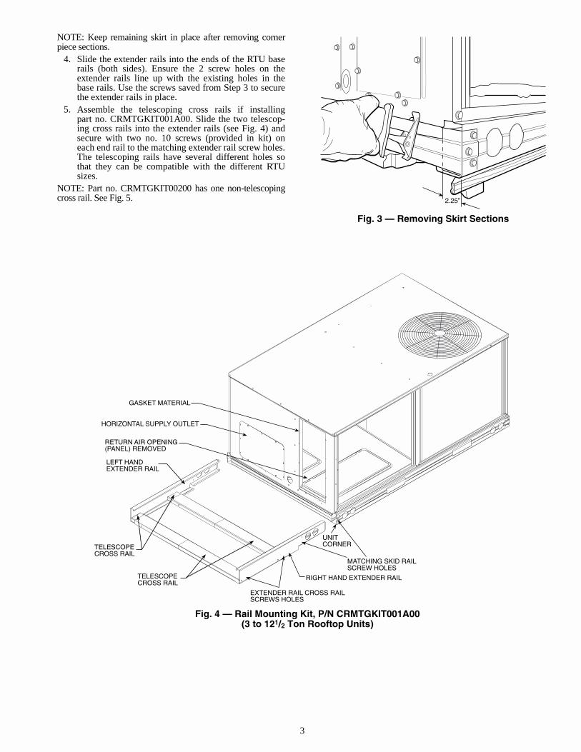
1. Two small sections on each side of the sheet metalskirt (on the supply side and return side of the RTU)must be removed to install the extender rails. Use thepaper template in the back of this installation manualto mark the location (both sides) where the cuts will bemade. See Fig. 3.
NOTE: RTU units manufactured after serial number 1499Ghave starter notches in the skirt to identify location for sawcuts.
2. Using a reciprocating saw or similar tool, saw com-pletely through the skirt from top to bottom on eachside of the unit. See Fig. 3. Use care to avoid damagingunit end panels.
3. Remove the three screws from the RTU that are hold-ing the corner piece of the skirt in place. Save screwsfor later use. Remove and discard corner piece sectionsexposing open ends of rooftop unit skirt.
ITEM QTY
CRMTGKIT001A00 CRMTGKIT002A00Crossrail 2 1Extender Rail 2 2
Return Air Baffle 1 1Return Air Side Baffle 2 2Wire Guard 1 1
No. 10 Screw 12 121/4-in. Self-Drilling Screw 18 22PVC Elbow and Nipple 1 of each 1 of each
Gasket 9 ft 14 ftHose N/A 42 in.
ITEM QTYHood Top* 2Hood Side† 4End Cap 1Aluminum Filter Screen 1Barometric Relief Damper 1Exhaust Hood Wire Guard 1Hinge 1Hinge Pin 1Exhaust Damper Limiter 1Gasket 1Sheet Metal Screw 36Knob (for thermostats) 2Small Machine Screw (for thermostats) 4
IMPORTANT: The mounting rail kit must be installedon the RTU before the Energy$Recycler unit is rigged.See Fig. 2. Package contents for the Mounting Rail Kitaccessory are listed in Table 1.
Fig. 2 — Energy$Recycler Attached to RTU
Fig. 1 — 62AQ Energy$Recycler
3
NOTE: Keep remaining skirt in place after removing cornerpiece sections.
4. Slide the extender rails into the ends of the RTU baserails (both sides). Ensure the 2 screw holes on theextender rails line up with the existing holes in thebase rails. Use the screws saved from Step 3 to securethe extender rails in place.
5. Assemble the telescoping cross rails if installingpart no. CRMTGKIT001A00. Slide the two telescop-ing cross rails into the extender rails (see Fig. 4) andsecure with two no. 10 screws (provided in kit) oneach end rail to the matching extender rail screw holes.The telescoping rails have several different holes sothat they can be compatible with the different RTUsizes.
NOTE: Part no. CRMTGKIT00200 has one non-telescopingcross rail. See Fig. 5. 2.25”
Fig. 3 — Removing Skirt Sections
LEFT HANDEXTENDER RAIL
RETURN AIR OPENING(PANEL) REMOVED
HORIZONTAL SUPPLY OUTLET
GASKET MATERIAL
TELESCOPECROSS RAIL
TELESCOPECROSS RAIL
RIGHT HAND EXTENDER RAIL
UNITCORNER
EXTENDER RAIL CROSS RAILSCREWS HOLES
MATCHING SKID RAILSCREW HOLES
Fig. 4 — Rail Mounting Kit, P/N CRMTGKIT001A00(3 to 121/2 Ton Rooftop Units)

4
Step 3 — Rig Accessory Energy$RecyclerUnit — Keep Energy$Recycler unit upright and do not drop.Spreader bars are not required if top crating (Fig. 6) is left onunit. See Table 3 and Fig. 7 and 8 for unit weight, physical data,and dimensions.
Energy$Recycler unit is heavy. Take proper safety precau-tions to avoid personal injury or unit damage when movingthe unit.
Be sure all unit panels are securely in place prior to rigging.
TOP CRATE
BOTTOMWOODENSKID
HOOD KIT
BANDINGMATERIAL
BRACKET
FILTERACCESSPANEL
SUPPLYBLOWERACCESSPANEL
Fig. 6 — Packaging Assembly
LEFT HANDEXTENDER RAIL
CROSS RAIL
RIGHT HANDEXTENDER RAIL
Fig. 5 — Rail Mounting Kit, P/N CRMTGKIT002A00(71/2 to 121/2 Ton Rooftop Units)

5
Fig
. 7 —
Bas
e U
nit
Dim
ensi
on
s, 6
2AQ
060
and
62A
Q10
0
UN
ITE
LE
CT
RIC
AL
CH
AR
AC
TE
RIS
TIC
SU
NIT
WT.
UN
IT H
EIG
HT
mm
[in
.]C
EN
TE
R O
F G
RA
VIT
Ym
m [
in.]
Lb
Kg
“A”
XY
62A
Q06
020
8/23
0-1-
6022
510
280
9.4
[31.
87]
419.
0 [1
6.50
]27
9.4
[11.
00]
62A
Q10
020
8/23
0-1-
6024
010
980
9.4
[31.
87]
419.
0 [1
6.50
]27
9.4
[11.
00]
RE
QU
IRE
D C
LE
AR
AN
CE
S T
O C
OM
BU
ST
IBL
E M
AT
L.
MIL
LIM
ET
ER
S [I
N.]
All
Sid
es. .
. . .
. . .
. . .
. . .
. . .
. . .
. . .
. . .
. . .
. . .
. . .
. . .
. . .
. . .
. .
0 [0
]
NE
C R
EQ
UIR
ED
CL
EA
RA
NC
ES
Bet
wee
n U
nit (
Con
trol
Box
/Exh
aust
Sid
e) a
ndU
ngro
unde
d S
urfa
ces
. . .
. . .
. . .
. . .
. . .
. . .
. . .
. . .
. . .
. 91
4.0
[36.
00]
And
Blo
ck o
r C
oncr
ete
Wal
ls a
nd O
ther
Gro
unde
d S
urfa
ces
. . .
. . .
. . .
. . .
. . .
. . .
. . .
. . .
. . .
. .
1066
.8 [4
2.00
]R
EQ
UIR
ED
CL
EA
RA
NC
E F
OR
OP
ER
AT
ION
AN
D S
ER
VIC
ING
Filt
er A
cces
s S
ide
. . .
. . .
. . .
. . .
. . .
. . .
. . .
. . .
. . .
. . .
. 76
2.0
[30.
00]
Sup
ply-
Air
Inta
ke .
. . .
. . .
. . .
. . .
. . .
. . .
. . .
. . .
. . .
. . .
. 91
4.0
[36.
00]
Uni
t Top
. . .
. . .
. . .
. . .
. . .
. . .
. . .
. . .
. . .
. . .
. . .
. . .
. . .
. . .
. . .
. 0
[0]
Exh
aust
Air
Sid
e .
. . .
. . .
. . .
. . .
. . .
. . .
. . .
. . .
. . .
. . .
. 91
4.0
[36.
00]
Duc
t Sid
e. .
. . .
. . .
. . .
. . .
. . .
. . .
. . .
. . .
. . .
. . .
. . .
. . .
. . .
. . .
. 0
[0]
Mus
t be
atta
ched
to
duct
wor
k or
mat
ed t
o C
arri
er u
nit
size
s (0
04-0
14)
usin
g ac
cess
ory
kit C
RM
TG
KIT
001A
00.
Dim
ensi
ons
in [
] a
re in
inch
es.
CG
C
ente
r of
Gra
vity
Dire
ctio
n of
Airf
low

6
Fig
. 8 —
Bas
e U
nit
Dim
ensi
on
s, 6
2AQ
200
and
62A
Q30
0
UN
ITE
LE
CT
RIC
AL
CH
AR
AC
TE
RIS
TIC
SU
NIT
WT.
UN
IT H
EIG
HT
mm
[in
.]C
EN
TE
R O
F G
RA
VIT
Ym
m [
in.]
Lb
Kg
“A”
XY
62A
Q20
020
8/23
0-1-
60, 2
08/2
30-3
-60,
460
-3-6
045
120
510
12.4
[39.
86]
759
.71
[29.
91]
381.
00 [1
5.00
]62
AQ
300
208/
230-
3-60
, 460
-3-6
049
322
410
12.4
[39.
86]
772
.41
[30.
41]
368.
30 [1
4.50
]
RE
QU
IRE
D C
LE
AR
AN
CE
S T
O C
OM
BU
ST
IBL
E M
AT
L.
MIL
LIM
ET
ER
S [I
N.]
All
Sid
es. .
. . .
. . .
. . .
. . .
. . .
. . .
. . .
. . .
. . .
. . .
. . .
. . .
. . .
. . .
. .
0 [0
]N
EC
RE
QU
IRE
D C
LE
AR
AN
CE
SB
etw
een
Uni
t (C
ontr
ol B
ox/E
xhau
st S
ide)
And
Ung
roun
ded
Sur
face
s. .
. . .
. . .
. . .
. . .
. . .
. . .
. . .
. . 9
14.0
[36.
00]
And
Blo
ck o
r C
oncr
ete
Wal
ls a
nd O
ther
Gro
unde
d S
urfa
ces
. . .
. . .
. . .
. . .
. . .
. . .
. . .
. . .
. . .
. .
1066
.8 [4
2.00
]
RE
QU
IRE
D C
LE
AR
AN
CE
FO
R O
PE
RA
TIO
N A
ND
SE
RV
ICIN
GF
ilter
Acc
ess
Sid
e .
. . .
. . .
. . .
. . .
. . .
. . .
. . .
. . .
. . .
. . .
762.
0 [3
0.00
]S
uppl
y-A
ir In
take
. . .
. . .
. . .
. . .
. . .
. . .
. . .
. . .
. . .
. . .
. .
914.
0 [3
6.00
]U
nit T
op .
. . .
. . .
. . .
. . .
. . .
. . .
. . .
. . .
. . .
. . .
. . .
. . .
. . .
. . .
. . .
0 [0
]E
xhau
st A
ir S
ide
. . .
. . .
. . .
. . .
. . .
. . .
. . .
. . .
. . .
. . .
. .
914.
0 [3
6.00
]D
uct S
ide
. . .
. . .
. . .
. . .
. . .
. . .
. . .
. . .
. . .
. . .
. . .
. . .
. . .
. . .
. . .
0 [0
]M
ust
be a
ttach
ed t
o du
ctw
ork
or m
ated
to
Car
rier
unit
size
s (0
08-0
14)
usin
g ac
cess
ory
kit C
RM
TG
KIT
002A
00.
Dim
ensi
ons
in [
] a
re in
inch
es.
CG
C
ente
r of
Gra
vity
Dire
ctio
n of
Airf
low

7
Table 3 — Physical Data
TXV — Thermostatic Expansion Valve
Step 4 — Attach the Energy$Recycler to theRooftop Unit (RTU)
1. Remove the screws on each end of the bottom woodenskids attached to the end of the Energy$Recycler unit.See Fig. 7-9.
2. Remove and discard the wooden skid by pulling itaway from the unit.
PREPARE THE RETURN AIR SECTION OF RTU TOACCEPT THE ENERGY$RECYCLER UNIT (Fig. 10 and11)
1. For RTU unit sizes 004-007, remove the return air ductcover. For RTU sizes 008-014, refer to Fig. 10 and 11for dimensions of piece to remove from the lower por-tion of the return air duct cover of the RTU. Drill 2pilot holes along the bottom edge of remaining pieceof the return air duct cover of the RTU, as shown inFig. 10 and 11. Save the top piece for reinstallation onthe RTU.
2. Place gasket material (provided in rail mounting kit)around the perimeter of the return opening of the RTU.See Fig. 4, 5, 10 and 11.
UNIT 62AQ
060 100 200 300OPERATING WEIGHT (lb) 225 240 451 493Accessory Mounting Kit (lb) 30 30 59 59SHIPPING WEIGHT (lb) 245 260 487 529
COMPRESSOR Rotary ReciprocatingQuantity 1 1 1 1Oil (cc) 550 550 1922 1922Suction Line Diameter (in.) 1/2 1/2 3/4 3/4Discharge Line Diameter (in.) 3/8 3/8 1/2 1/2Liquid Line Diameter (in.) 3/8 3/8 3/8 3/8
REGRIGERANT TYPE R-22 Operating Charge (lbs) 2 3 6 8
EVAPORATOR COIL (SUPPLY COIL) High-Efficiency Enhanced Copper Tubes, Lanced Aluminum FinsTXV + Acutrol™ Feed Device
Number of Circuits 2 3 4 8Rows...Fins/in. 2...15 2...15 2...15 2...15Total Face Area (sq ft) 1.4 2 3.7 5.6
EXHAUST FAN Centrifugal TypeSize (Diameter x Width) 7.12 x 6 7.12 x 6 10 x 10 10 x 10Nominal Cfm 600 1000 2000 3000Bhp 1/6 1/2 1/2 1/2Motor Frame 48 48 48 56Nominal Fan Rpm 1125 1735 1075 1750Motor Bearing Type Ball Ball Ball BallMaximum Fan Rpm 1950 1950 1950 1950Nominal Motor Shaft Diameter (in.) 1/2 1/2 1/2 5/8Type Direct Drive Fan Direct Drive Fan Direct Drive Fan BeltMotor Pulley — — 2.8 3.8Fan Pulley — — 4.5 4.5Belt — — — A37
OPTIONAL SUPPLY FANSize (Diameter x Width) 7.12 x 6 7.12 x 6 10 x 10 11 x 10Nominal Cfm 600 1000 2000 3000Hp 1/6 1/2 1/2 1Motor Frame 48 48 48 48Nominal Fan Rpm 1125 1735 1075 1040Motor Bearing Type Ball Ball Ball BallMaximum Fan Rpm 1950 1950 1200 1280Nominal Motor Shaft Diameter (in.) 1/2 1/2 1/2 1/2Type Direct Drive Fan Direct Drive Fan Direct Drive Fan Direct Drive Fan
CONDENSER COIL (EXHAUST COIL) High-Efficiency Enhanced Copper Tubes, Lanced Aluminum FinsTXV + Acutrol Feed Device
Number of Circuits 2 3 4 8Rows...Fins/in. 2...15 3...15 2...15 3...15Total Face Area (sq ft) 2 2 5.6 5.6
HIGH PRESSURE SWITCH (psig)428320
CutoutReset (Auto.)
OUTDOOR-AIR INLET SCREEN CleanableQuantity...Size (in.) 1...20x24x1 1...20x42x1
SUPPLY AND EXHAUST AIR FILTERS ThrowawayQuantity...Size (in.) 1...12x24x1 2...16x25x2
IMPORTANT: Before attaching the Energy$Recycler tothe rooftop unit, remove the rooftop unit’s condensatetrap (if previously installed) by turning it counterclock-wise and unscrewing it. Save condensate trap for lateruse. When the rooftop unit and the Energy$Recycler areconnected, the rooftop equipment’s condensate drainline will drain into the Energy$Recycler’s condensatepan.
Do not overlap gasket material, as it will cause water leaks.

8
3. Remove the rooftop equipment’s filter rack assemblyby removing the screws that hold the rack in place.Pull assembly out of cabinet and set aside.
4. Position the Energy$Recycler unit to the rooftopequipment by setting the Energy$Recycler unit’s filteraccess side base rails over the newly installed extendedrails on the filter access side of the rooftop unit. SeeFig. 12-14.
NOTE: The base rail on all Energy$Recycler units will project2 in. over the extended mounting rail on the filter access side.See Fig. 13 and 14. The base rail opposite the filter access sideon the 62AQ200 and 62AQ300 models will project 2 in. overthe extender mounting rail when installed on a large rooftopunit. See Fig. 14.
5. Pull the wire harness from the Energy$Recycler unitdirectly through the rooftop unit’s horizontal return airduct opening, sliding both units together. Plug 12-pinrooftop unit plug into plug from Energy$Recycler unit.
6. With the Energy$Recycler unit positioned, gently pullthe insulation back from the rooftop unit exposing theexisting engagement holes.
7. Fasten the units together with the 1/4-in. self-drillingscrews by drilling into the Energy$Recycler unitthrough the engagement holes around the perimeter ofthe RTU’s duct cover opening. On RTU unit sizes 008-014, two of the holes along the bottom edge of theremaining piece of the return air duct cover shouldhave been drilled in Step 1, when the return air ductcover was modified. See Fig. 10 and 11.
8. Reinstall the filter rack frame in the rooftop unit.Refasten the screws to hold the filter rack in place.
9. Reinstall the filters.10. Assemble return air baffle assembly per Fig. 15 and
16. Attach return air baffle to side baffles with screwsprovided. The wire guard has 2 wire legs that slide intoreturn air baffle predrilled holes, on top.
11. Mount return air baffle assembly into the return airsection of the rooftop equipment as shown in Fig. 15and 16. Secure with screws provided.
NOTE: Return air baffle assembly prevents circulation of airthrough the Energy$Recycler unit.
ALL PANELS MUST BE IN PLACE WHEN RIGGING.CAUTION - NOTICE TO RIGGERS:
Hook rigging shackles through holes in base rail, as shown.Use wooden top skid, when rigging, to prevent rigging strapsfrom damaging unit.
60AQ500132
MM IN MM IN MMUNIT
62AQ06062AQ100
MAX WEIGHTLB KG IN.
A B C
245260
111118
34.50 876 17.25 438 33.38 848. .
62AQ20062AQ300
487529
221240
62 1515 31 788 41.38 1050
"B"914 - 137(36" - 54")
"C"
"A"
Fig. 9 — Energy$Recycler UnitRigging Information
A
B
25 1/2”
.50 x .50 GASKET MATERIALAROUND OPENING
UPPER ENGAGEMENTHOLES
B
33 3/8”
A
0.50 x 0.50 SEAL STRIPAROUND OPENING
Fig. 10 — Preparing RTU Return-Air Opening to Accept Energy$Recycler,
62AQ060 and 62AQ100 Units
UNIT SIZE DIM A (in.)(Top Piece of Panel)
DIM B (in.)(Panel)
008, 009 93/16 3411/16
012, 014 117/8 373/8
Fig. 11 — Preparing RTU Return-Air Opening to Accept Energy$Recycler,
62AQ200 and 62AQ300 Units
UNIT SIZE DIM A (in.)(Top Piece of Panel)
DIM B (in.)(Panel)
012, 014 4 373/8

9
Step 5 — Assemble and Mount Supply-AirHood and Outside Cooling and Heating Ther-mostats for the Energy$Recycler and SetOptional Supply-Air Fan Speed — The hood kitsupplied with the Energy$Recycler unit is needed to completethis installation. See Table 2 and Fig. 17. The Energy$Recyclerunit’s supply air hood installs around its motorized damperinlet.
1. Assemble and mount supply air hood as shown inFig. 17.
2. Discard the tape that holds the thermostats behind thedamper plates. Mount thermostats to the hood sides ofthe Energy$Recycler unit into the holes provided, withthermostat terminals facing up. See Fig. 17. Mountoutside cooling set point thermostat part numberHH22HA060 (white label) on the left side of the hood.See Fig. 17.
3. Mount the outside heating thermostat part numberHH22HA065 (red label) on the right side of the hood.See Fig. 17.
NOTE: Mount the hood sides to the Energy$Recyclerunit first, and then the hood top for easier installation.The thermostats are shipped factory-wired and tapedbehind the damper blade of the 62AQ Energy$Recyclerunit. Knobs and screws are in hood package.
SUPPLYOPENING
EXHAUSTINLET
7.5-12.5 TONKNOCKOUT
3-6 TONKNOCKOUT
MOUNTING RAILS(P/N CRMTGKIT001A00)
ENERGY$RECYCLER
2”PROJECTION
FILTERACCESSSIDE
62AQ060/62AQ100 INSTALLEDON 3-6 TON UNIT
ROOFTOP UNIT
MOUNTING RAILS(P/N CRMTGKIT001A00)
ENERGY$RECYCLER
2”PROJECTION
FILTERACCESSSIDE
62AQ060/62AQ100 INSTALLEDON 7.5-12.5 TON UNIT
ROOFTOP UNIT
MOUNTING RAILS(P/N CRMTGKIT002A00)
ENERGY$RECYCLER
2”PROJECTION
FILTERACCESSSIDE
62AQ200/62AQ300 INSTALLEDON 7.5-12.5 TON UNIT
ROOFTOP UNIT
Fig. 12 — Knockout Location Fig. 14 — Top View of 62AQ200 and 62AQ300Energy$Recycler Installation
Fig. 13 — Top View of 62AQ060 and 62AQ100 Energy$Recycler Installation

10
GRILLE
RETURN AIRSIDE BAFFLE
RETURN AIRSIDE BAFFLE
RETURN AIR BAFFLE
PACKAGE UNIT FILTER RACK
VERTICAL RETURN AIR INLET
GRILLE
RETURN AIRSIDE BAFFLE
RETURN AIRSIDE BAFFLE
RETURN AIRBAFFLE
Fig. 15 — Return-Air Baffle (62AQ060, 62AQ100 Unit Shown)
Fig. 16 — Return-Air Baffle (62AQ200, 62AQ300 Unit Shown)

11
4. From the outside of the unit’s side panels fasten thethermostat(s) with two mounting screws, with thequick connect terminals face up. See Fig. 17.
5. Install thermostat knobs (provided in kit). See Fig. 17.6. Set supply air quantity (on units with optional factory-
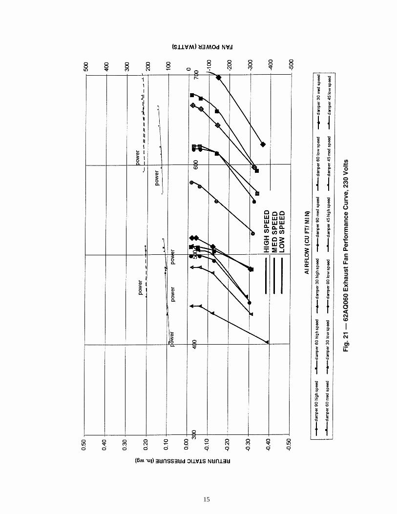
installed supply air fan (GA) or field-installed acces-sory supply air fan kit [CRFANKIT001-006A00]).Select the fan speed and damper position to obtaindesired cfm (see fan performance curve data, Fig. 18-35). Relocate damper stops to the desired position onthe damper support rail and adjust the fan speed byrelocating the wire on the supply fan motor terminalblock. Factory set position is 45 degrees for thedamper position, and medium speed for the motor.Relocate stops to top hole for 30 degrees, bottom holefor 60 degrees, and remove stops for 90 degrees (seeFig. 17).
7. Install the aluminum filter screen and end cap withscrews along the top, as shown in Fig. 17.
Step 6 — Mount the Barometric Relief Damperand Exhaust Hood Assembly and AdjustExhaust Fan — The hood kit supplied with the Ener-gy$Recycler unit is needed to complete this installation. Theexhaust air hood (that includes the barometric relief damper)must be assembled and installed on the 62AQ unit per the in-structions below. See Fig. 36.
1. Install the barometric relief damper onto theEnergy$Recycler by mounting the hinge with 2 screwsthen sliding in the hinge pin. See Fig. 36.
2. Install damper limiter for 30, 45, or 60 degree angles.Limiter pin not required for 90-degree setting (set tothe desired position based on CFM requirements andfan speed). See Fig. 36. Fan speed is adjusted by relo-cating wires on fan terminal blocks. On the 62AQ300size, adjust fan speed by changing the pulley setting.
3. Adjust exhaust fan speed (62AQ300 only). Adjustcondenser/exhaust fan speed to meet application con-ditions. Refer to Fig. 35.
To change fan speeds:a. Shut off unit power supply.b. Loosen belt by loosening fan motor mounting
nuts.c. Loosen movable pulley flange setscrew.d. Screw movable flange toward fixed flange to
increase speed and away from fixed flange todecrease speed. Increasing fan speed increasesload on motor.
e. Set movable flange at nearest keyway of pulleyhub and tighten setscrew.
To align fan and motor pulleys:a. Loosen fan pulley setscrews.b. Slide fan pulley along fan shaft.c. Make angular alignment by loosening motor from
mounting plate.To adjust belt tension:a. Loosen fan motor mounting nuts.b. Slide motor mounting plate away from fan scroll
for proper belt tension (1/2-in. deflection with onefinger) and tighten mounting nuts.
c. Adjust bolt and nut on mounting plate to securemotor in fixed position.
4. Loosen compressor bolts and remove shipping blocksfrom under compressor on the 62AQ060 and 62AQ100sizes only.
5. Install exhaust hood as shown in Fig. 36.6. Install wire guard as shown in Fig. 36.
Never operate the unit without the wire guard in place.
HOODSIDE
KNOB
END CAP
TEMPERATURE SWITCHSHIPPED WITH UNIT
ALUMINUM FILTER SCREEN
COOLING SET POINTTHERMOSTAT (WHITE LABEL)
HOOD SIDE
KNOB
DAMPER BLADE STOPSHIPPED WITH UNITIN 45° POSITION
HOOD TOP
LTLOMOUNTINGBRACKET
TEMPERATURECOOLINGLOCKOUT (LTLO)
HEATING POINTTHERMOSTAT(RED LABEL)
SCREW INSTALLATION (2)
SCREWS (2)
Fig. 17 — Supply-Air Hood Assembly

12
Fig
. 18
— 6
2AQ
060
Su
pp
ly F
an P
erfo
rman
ce C
urv
e, 2
08 V
olt
s

13
Fig
. 19
— 6
2AQ
060
Su
pp
ly F
an P
erfo
rman
ce C
urv
e, 2
30 V
olt
s

14
Fig
. 20
— 6
2AQ
060
Exh
aust
Fan
Per
form
ance
Cu
rve,
208
Vo
lts
15
Fig
. 21
— 6
2AQ
060
Exh
aust
Fan
Per
form
ance
Cu
rve,
230
Vo
lts

16
Fig
. 22
— 6
2AQ
100
Su
pp
ly F
an P
erfo
rman
ce C
urv
e, 2
08 V
olt
s

17
Fig
. 23
— 6
2AQ
100
Su
pp
ly F
an P
erfo
rman
ce C
urv
e, 2
30 V
olt
s

18
Fig
. 24
— 6
2AQ
100
Exh
aust
Fan
Per
form
ance
Cu
rve,
208
Vo
lts

19
Fig
. 25
— 6
2AQ
100
Exh
aust
Fan
Per
form
ance
Cu
rve,
230
Vo
lts

20
Fig
. 26
— 6
2AQ
200
Su
pp
ly F
an P
erfo
rman
ce C
urv
e, 2
08 V
olt
s

21
Fig
. 27
— 6
2AQ
200
Su
pp
ly F
an P
erfo
rman
ce C
urv
e, 2
30 V
olt
s

22
Fig
. 28
— 6
2AQ
200
Su
pp
ly F
an P
erfo
rman
ce C
urv
e, 4
60 V
olt
s

23
Fig
. 29
— 6
2AQ
200
Exh
aust
Fan
Per
form
ance
Cu
rve,
208
Vo
lts

24
Fig
. 30
— 6
2AQ
200
Exh
aust
Fan
Per
form
ance
Cu
rve,
230
Vo
lts

25
Fig
. 31
— 6
2AQ
200
Exh
aust
Fan
Per
form
ance
Cu
rve,
460
Vo
lts

26
Fig
. 32
— 6
2AQ
300
Su
pp
ly F
an P
erfo
rman
ce C
urv
e, 2
08 V
olt
s

27
Fig
. 33
— 6
2AQ
300
Su
pp
ly F
an P
erfo
rman
ce C
urv
e, 2
30 V
olt
s

28
Fig
. 34
— 6
2AQ
300
Su
pp
ly F
an P
erfo
rman
ce C
urv
e, 4
60 V
olt
s

29
Fig
. 35
— 6
2AQ
300
Exh
aust
Fan
Per
form
ance
Cu
rve,
208
, 230
, 460
Vo
lts

30
Step 7 — Set the Outdoor Cooling and Heat-ing Thermostats
COOLING — During the unoccupied period, the economizermode of operation is used as the first stage of cooling. Whenthe outside air temperature is below the cooling thermostat setpoint, the outside air will be used for first stage cooling. HEATING — The heating thermostat should be adjustedto the second stage balance point (heat output of theEnergy$Recycler plus the heat output of the first stage on roof-top unit equals building load at this temperature). Above thissetting, first stage heating will be the 62AQ unit and secondstage will be the first stage of the rooftop unit. Below this pointfirst stage heating will be the 62AQ unit plus first stage heatingof the rooftop unit. The second stage will be the second stage ofthe rooftop unit.
Step 8 — Install Condensate Lines and Fit-tings on Rooftop Unit62AQ060 AND 62AQ100 ENERGY$RECYCLER UNITS
1. Remove control access panel from the Energy$Recy-cler unit (see Fig. 7).
2. Install the PVC nipple and elbow (from the accessoryMounting Rail kit) in the female 3/4-in. condensatedrain outlet of the rooftop unit. Condensate from the
rooftop unit will drain through this fitting directly intothe Energy$Recycler unit’s lower coil condensate pan.
62AQ200 AND 62AQ300 ENERGY$RECYCLER UNITS1. Remove control access panel and the supply blower
access panel from the Energy$Recycler unit. SeeFig. 8).
2. Attach the threaded end of the 3/4-in. nipple (shippedin the accessory Mounting Rail kit) into the RTU.
3. Slide one end of the 3/4-in. tubing through the hole inthe coil mounting bracket. Attach to the barbed end ofthe nipple.
4. Connect the opposite end of the 3/4-in. tubing to oneend of the elbow, ensuring that the open end of theelbow will drain properly into the condensate pan.
NOTE: The condensate from the rooftop unit along with thecondensate from the upper coil will drain out of theEnergy$Recycler unit. The 62AQ condensate outlet must havea field-fabricated P-trap installed. Install the trap at least 4 in.deep and protect against freeze-up. If drain line is installeddownstream from the external trap, pitch the line away fromthe rooftop unit at 1 in. per 10 ft of run. Do not use a pipesmaller than the unit connection.
Step 9 — Make Electrical Connections
IMPORTANT: The 62AQ unit is shipped with an out-door thermostat set at 55 F which locks out mechanicalcooling on the RTU and the 62AQ compressor. If thisfeature is not desirable, the rooftop unit’s compressorcan be allowed to run by relocating both gray wires tothe same side of the Low Temperature Lockout Thermo-stat (LTLO) leaving the white wire on the opposite pole,locking out only the 62AQ compressor. The LTLO isalso accessible by removing the filter access panel andthe door of the damper mounting bracket. Refer to Trou-bleshooting section.
Unit cabinet must have an uninterrupted, unbroken electri-cal ground to minimize the possibility of personal injury ifan electrical fault should occur. This ground may consist ofelectrical wire connected to unit ground wire in powercompartment, or conduit approved for electrical groundwhen installed in accordance with NEC (National Electri-cal Code) ANSI/NFPA (American National StandardsInstitute/National Fire Protection Association) latest revi-sion, and local electrical codes. Failure to follow this warn-ing could result in the installer being liable for personalinjury of others.
HOOD SIDE
HOOD TOP
HINGE
HINGE PIN
BAROMETRICRELIEF DAMPER
60° LOCATION
HOOD SIDE
DAMPER LIMITER
WIRE GUARD
30° LOCATION
45° LOCATION
Fig. 36 — Barometric Exhaust Air Hood Assembly

31
FIELD POWER SUPPLY — All units except 208/230-vunits are factory wired for the voltage shown on the nameplate.If the 208/230-v unit is to be connected to a 208-v power sup-ply, the transformer must be rewired by disconnecting the blackwire from the 230-v tap on the transformer and relocating it tothe 208-v tap on the transformer.
Refer to unit label diagram for additional information. Pig-tails are provided for field wire connections. Use UL (Under-writers’ Laboratories) approved connector.
When installing units, provide a disconnect per the NEC.All field wiring must comply with the NEC and local
requirements.Install field wiring as follows:
1. Connect conduit to side panel opening.2. Splice power lines to pigtails in splice compartment.
During operation, voltage to compressor terminals must bewithin range indicated on unit nameplate (also see Tables 4Aand 4B).INSTALLING ACCESSORY 62AQ ON A COMMONPOWER SUPPLY WITH ALL RTUs (EXCEPT RTU SIZE014 230-V UNITS, AND 230-V 62AQ ON A 460-VPOWER SUPPLY)Perform the following steps:
1. For the combination load ratings for minimum circuitamps (MCA) and maximum overcurrent protectivedevice (MOCP), add “X” amps, found on the 62AQnameplate and Table 4B, to the values of MCA andMOCP for the RTU. If the calculated new MOCP isnonstandard, select the next lowest size for the com-bined MOCP rating. If the combined MOCP rating isnow less than the MCA, select the next higher size forthe MOCP.
2. Provide a disconnect for the 62AQ unit:• If the new MOCP is less than or equal to 60 amps,
a common non-fused disconnect for the 62AQ andRTU may be used provided that: 1) the wire size tothe 62AQ unit is at least 20 amps; and 2) the dis-connect size is at least equal to the disconnect sizemarked on the RTU plus Y marked on the 62AQnameplate and Table 4B.
• If the MOCP is greater than 60 amps, provide aFUSED DISCONNECT for the 62AQ unit sizedper the 62AQ unit nameplate and Table 4B.
3. Provide a disconnect for the RTU:• If the new MOCP is less than or equal to 60 amps,
a common non-fused disconnect sized per Step 2above may be used for the 62AQ and RTU.
• If the new MOCP is greater than 60 amps, and theold MOCP was less than or equal to 60 amps, aFUSED DISCONNECT no greater than 60 ampsmust be provided for the RTU.
• If the old overcurrent protection device is greaterthan 60 amps, a non-fused disconnect sized pernameplate marking maybe used for the RTU.
INSTALLING ACCESSORY 62AQ ON A COMMONPOWER SUPPLY WITH ALL SIZE 014 230-V RTUsPerform the following steps:
1. For the combination load ratings for minimum circuitamps (MCA) and maximum over current protective
device (MOCP), add “X” amps, found on the 62AQunit nameplate and Table 4B, to the values of MCAand MOCP for the RTU. If the calculated new MOCPis nonstandard, select the next lowest size for thecombined MOCP rating. If the combined MOCP rat-ing is now less than the MCA, select the next highersize for the MOCP.
2. Provide a FUSED DISCONNECT for the 62AQ unitsized per the 62AQ nameplate and Table 4B.
3. Provide a disconnect for the RTU:• If installing on units without electric heat a FUSED
DISCONNECT sized per nameplate is required forthe RTU.
• If installing on units with electric heat, a non-fuseddisconnect sized per nameplate marking may beused for the RTU.
INSTALLING ACCESSORY 62AQ SIZES 060 AND 100(230 V) ON A COMMON POWER SUPPLY WITH ALL460-V RTUsPerform the following steps:
1. For the combination load ratings for minimum circuitamps (MCA) and maximum over current protectivedevice (MOCP), add “X” amps, found on the 62AQnameplate and Table 4B, to the values of MCA andMOCP marked the RTU. If the calculated new MOCPis nonstandard, select the next lowest size for the com-bined MOCP rating. If the combined MOCP rating isnow less than the MCA, select the next higher size forthe MOCP.
2. Provide a disconnect for the 62AQ unit:• If the new MOCP is less than or equal to 30 amps, a
common non-fused disconnect for the 62AQ andRTU may be used provided that: 1) the wire size to62AQ is at least 10 amps; and 2) the disconnect sizeis at least equal to the disconnect size marked onthe RTU plus Y marked on the 62AQ unit name-plate and Table 4B.
• If the MOCP is greater than 30 amps, provide aFUSED DISCONNECT for the 62AQ unit sizedper the 62AQ nameplate and Table 4B.
3. Install a 460 to 230 stepdown transformer (part num-ber HT01AH853) downstream of the 62AQ unitdisconnect.
4. Provide a disconnect for the RTU:• If the new MOCP is less than or equal to 30 amps, a
common non fused disconnect sized per Step 2above may be used for the 62AQ and RTU.
• If the new MOCP is less than or equal to 60 amps, anon-fused disconnect sized per nameplate markingmay be used for this unit.
• If the new overcurrent protection device is greaterthan 60 amps, and the old overcurrent protectiondevice was less than 60 amps, a FUSED DISCON-NECT no greater than 60 amps must be providedfor this unit.
• If the old overcurrent protection device is greaterthan 60 amps, a non-fused disconnect sized pernameplate marking maybe used for this unit.

32
Table 4A — Electrical Data — 62AQ
LEGEND FOR TABLE 4A AND 4B
*Fuse or HACR circuit breaker per NEC.
†62AQ with factory-installed supply fan option or field-installedaccessory as shown below:
Table 4B — Electrical Data —62AQ MOCP Correction
*62AQ with factory-installed supply fan option or field-installedaccessory as shown below:
Light Commercial Thermidistat AccessoryGENERAL — A Light Commercial Thermidistat Accessory(part number TSTATCCPLH01-B) is available for eachEnergy$Recycler unit for field installation to control theEnergy$Recycler. See Fig. 37.
The Light Commercial Thermidistat is a 7-day programma-ble, wall-mounted, low-voltage control which combines tem-perature and humidity control in a single unit. It provides sepa-rate set points for heating and cooling, and adds dehumidifica-tion with separate set points for occupied and unoccupiedperiods. Different heating and cooling set points and times are
programmable for up to 4 periods per day and 7 days per week.The dehumidification output provides direct control of humidi-ty. During power loss an internal memory stores programs andsettings for unlimited time, and the clock continues to run for atleast 8 hours. Batteries are not used.POWER — Note that this control does not require batteriesand is not “power stealing.” It does require 24 vac (R and Cterminals) from the RTU’s low-voltage transformer to be con-nected to it for proper operation. The control will not operatewithout these 2 connections. See Fig. 38.DEHUMIDIFICATION EQUIPMENT AND CONNEC-TIONS — The dehumidification output terminals on theLight Commercial Thermidistat must be connected to thedehumidify input terminals on the 62AQ Energy$Recycler.Additionally, if the RTU is equipped with optionalMoistureMi$er™ Dehumidification accessory, a relay in theEnergy$Recycler (HM) energizes the MoistureMi$er solenoidto activate the enhanced dehumidification mode. See LightCommercial Thermidistat installation instructions for more in-formation on these and other applications.
UNITSIZE62AQ
V-PH-HzVOLTAGE RANGE COMPRESSOR
FANS MOTORPOWER SUPPLY
SUPPLY EXHAUSTMin Max RLA LRA FLA FLA MCA MOCP*
060 208/230-1-60 187 254 7 29 — 1.1 9.9 15060GA† 208/230-1-60 187 254 7 29 1.1 1.1 11.0 15
100 208/230-1-60 187 254 10.5 38 — 2.3 15.4 25100GA† 208/230-1-60 187 254 10.5 38 2.3 2.3 17.7 25
200 208/230-1-60 187 254 17.9 87 — 4.2 26.6 40200GA† 208/230-1-60 187 254 17.9 87 4.2 4.2 30.8 40
200 208/230-3-60 187 254 13.5 110 — 4.2 21.1 35200GA† 208/230-3-60 187 254 13.5 110 4.2 4.2 25.3 35
200 460-3-60 414 506 6.4 54 — 1.9 9.9 15200GA† 460-3-60 414 506 6.4 54 1.9 1.9 11.8 15
300 208/230-3-60 187 254 17.2 137 — 6.7 28.2 40300GA† 208/230-3-60 187 254 17.2 137 5.9 6.7 34.1 40
300 460-3-60 414 506 9 69 — 3.2 14.5 20300GA† 460-3-60 414 506 9 69 3.6 3.2 18.1 20
FLA — Full Load AmpsFU — FuseHACR — Heating, Air Conditioning and
RefrigerationLRA — Locked Rotor AmpsMCA — Minimum Circuit AmpsMOCP — Maximum Overcurrent ProtectionNEC — National Electrical CodeRLA — Rated Load Amps
UNIT SIZE V-PH (60 HZ) ACCESSORY FAN KITPART NUMBER
060 208/230-1 CRFANKIT001A00100 208/230-1 CRFANKIT002A00
200208/230-1 CRFANKIT003A00208/230-3 CRFANKIT003A00
460-3 CRFANKIT004A00
300208/230-3 CRFANKIT005A00
460-3 CRFANKIT006A00
UNITSIZE62AQ
INSTALLATION COMMON POWER SUPPLY62AQ 230 Volt RTU 460 Volt RTU
V-Ph (60 Hz) X Y X Y060 208/230-1 8.1 9.3 4.1 4.7
060GA* 208/230-1 9.2 11.0 4.6 5.3100 208/230-1 12.8 15.0 6.4 7.4
100GA* 208/230-1 15.1 17.0 7.6 8.7
200208/230-1208/230-3
460-3
22.117.7—
25.020.0—
——8.3
——9.5
200GA*208/230-1208/230-3
460-3
26.321.9—
30.025.0—
——
10.2
——
12.0
300 208/230-3460-3
23.9—
27.0—
—12.2
—14.0
300GA* 208/230-3460-3
29.8—
34.0—
—15.8
—18.0
UNIT SIZE V-PH (60 HZ) ACCESSORY FAN KITPART NUMBER
060 208/230-1 CRFANKIT001A00100 208/230-1 CRFANKIT002A00
200208/230-1 CRFANKIT003A00208/230-3 CRFANKIT003A00
460-3 CRFANKIT004A00
300208/230-3 CRFANKIT005A00
460-3 CRFANKIT006A00
Fig. 37 — Light Commercial Thermidistat Accessory
HEIGHT (in.) WIDTH (in.) DEPTH (in.)41/4 71/2 13/8

33
LIGHT COMMERCIAL THERMIDISTATACCESSORY INSTALLATION
Step 1 — Select Light Commercial ThermidistatLocationLight Commercial Thermidistat should be mounted:• Approximately 5 ft (1.5 m) from floor.• Close to or in a frequently used room, preferably on an
inside partitioning wall.• On a section of wall without pipes or ductwork.The Light Commercial Thermidistat should NOT be mounted:• Close to a window, on an outside wall, or next to a door
leading to the outside.• Exposed to direct light and heat from a lamp, sun, fire-
place, or other temperature-radiating object that maycause a false reading.
• Close to or in direct airflow from supply registers andreturn-air registers.
• In areas with poor air circulation, such as behind a dooror in an alcove.
Step 2 — Set DIP Switches — There is a 4-sectionDIP switch within the Light Commercial Thermidistat whichmust be properly set by the installer. It is easiest to set these 4switches before the Light Commercial Thermidistat is mountedto the wall, so complete the following steps first:
1. Open hinged Light Commercial Thermidistat cover.2. Remove cover completely by gently snapping it apart
at hinge.3. Switches are located in upper right corner of circuit
board. To change switch position, use corner of a smallscrewdriver to slide switch to opposite position.
4. After switches have been set, do not reassemble the2 halves. The rear plastic will be first mounted to wall.
SWITCH 1 — Not usedSWITCH 2 — Not used
SWITCH 3 — SMART/CONVENTIONAL RECOVERY —Selects between conventional or smart recovery from setback.Conventional recovery changes to new set point at prepro-grammed time. Smart recovery, which is active in both heatingand cooling, starts selected cycle 90 minutes earlier andsmoothly adjusts set point so room will arrive at programmedtemperature at programmed time.NOTE: The occupied output is only energized at the prepro-grammed time.To Set:OFF — for smart recovery. This is factory default.ON — for conventional recovery.SWITCH 4 — INSTALLER TEST OFF/ON — Selects aspecial installer test mode that assists with checkout and trou-bleshooting. See Step 5 — Conduct Light Commercial Ther-midistat Start-Up and Checkout.To Set:OFF — for normal operation. (Factory default setting.)ON — for Installer Test mode.
Step 3 — Install Light CommercialThermidistat
1. Turn off all power to equipment. Tag disconnect.2. If an existing thermostat is being replaced:
a. Remove existing thermostat from wall.b. Disconnect wires from existing thermostat, one at
a time.c. As each wire is disconnected, record wire color
and terminal marking.d. New or additional wire may be needed to accom-
modate added humidity outputs transformercommon.
e. Discard or recycle old thermostat.
3. Route wires through large hole in rear plastic. Levelrear plastic (separated from front plastic in Step 2 —Set DIP Switches, above). Level rear plastic againstwall (for aesthetic value only — Light CommercialThermidistat need not be leveled for proper operation)and mark wall through 2 mounting holes.
4. Drill two 3/16-in. mounting holes in wall wheremarked.
5. Secure rear plastic to wall with 2 screws and anchorsprovided. Additional mounting holes are available formore secure mounting if needed. Make sure all wiresextend through hole in mounting base.
6. Adjust length and routing of each wire to reach properconnector block and terminal on mounting base with1/4-in. extra length. Strip only 1/4 in. of insulation fromeach wire to prevent adjacent wires from shortingtogether when connected.
7. Match and connect equipment wires to proper termi-nals of each connector block. Remember R and C mustbe connected for proper operation (see Fig. 38).
Before installing Light Commercial Thermidistat, turn offall power to RTU and 62AQ units. There may be more thanone power disconnect. Electrical shock can cause personalinjury or death. Install lockout tags on disconnects.
Mercury is a hazardous waste and MUST be disposed ofproperly.
FOR MOISTUREMI$ER UNITS ONLY
LIGHTCOMMERCIALTHERMIDISTATACCESSORY
Fig. 38 — Light Commercial Thermidistat Accessory Low-Voltage Connections

34
8. Push any excess wire into wall and against rear plastic.Seal hole in wall to prevent air leaks. Leaks can affectoperation.
9. Reattach Light Commercial Thermidistat body tomounting base by first reattaching hinge.
10. Close Light Commercial Thermidistat assembly, mak-ing sure pins on back of circuit board align with sock-ets in connector.
11. Turn on power to equipment.On power up, all display segments will light for 2 seconds.
For the next 8 seconds, a 2-digit code appears on LED displaythat identifies Light Commercial Thermidistat configuration:
CP — Commercial Product
Step 4 — Set Light Commercial ThermidistatConfiguration (Fig. 39 and 40) — Configuration op-tions, like DIP switch settings, are intended to be selected at in-stallation and normally are not modified by the owner. Theseoptions must be made as part of the installation. A special pro-cedure allows entry into the Configuration mode. While in con-figuration mode, up to 10 selections can be made. A descrip-tion of each selection and how to use the Configuration modeare as follows:CONFIGURATION OPTIONS — SUMMARYOption 1 — Anticipator adjustmentOption 2 — Clean filter timer adjustmentOption 3 — English/Metric selectionOption 4 — Fan (G) ON with W selectionOption 9 — Holiday heat set pointOption 10 — Holiday cool set pointOption 11 — Holiday humidity set pointOption 13 — Room temperature offset adjustmentOption 14 — Heat cool deadband adjustmentOption 21 — Keyboard lockTO ENTER CONFIGURATION MODE — Press and holdFAN button for approximately 10 seconds until COOL setpoint display indicates a flashing “01”. The Light CommercialThermidistat is now in Configuration mode. It will automati-cally exit this mode if no button is pressed for 3 minutes. Press-ing HOLD End button will exit the Configuration modeimmediately.WHILE IN CONFIGURATION MODE — The upper small(COOL set point) display indicates selected option number andlarge display indicates selection made within that option. One ofthese will be flashing. The up and down set point buttons areused both to move between available options and to make selec-tion for each option. When option number (small display) isflashing, the up and down set point buttons allows for scrollingthrough options moving between available option numbers.After desired option number has been selected, press SETTIME/TEMP button once. The large display will now flash,indicating that up and down set point buttons now control avail-able choices within that option. Each press of SET TIME/TEMP button switches between available option (small display)and available selections within each option (large display).Option 1 — Anticipator Adjustment — This adjustment con-trols sensitivity and cycle rate of Light Commercial Thermidis-tat. Higher numbers decrease sensitivity and slow cyclerate. Lower numbers increase sensitivity and cycle rate. Antici-pator values can range from 1 to 9. Factory default is 3. Thisdefault selection provides optimum performance in nearly all
installations. Try it first; do not change setting unless there isevidence of need to do so.
Unlike conventional anticipators, this setting is not deter-mined by current draw. There is no need to measure, know, orcompensate for current draw. There is also no droop with thisLight Commercial Thermidistat. Regardless of setting andnumber of stages, both heating and cooling will control to theirrespective set points.TO ADJUST:
1. Enter Configuration mode. The upper small (COOLset point) display will be flashing 01. If not, use up anddown set point buttons to move it to 01.
2. Press SET TIME/TEMP button once to flash currentselection of 1, 2, 3, 4, 5, 6, 7, 8, or 9 on large display.Factory default is 3.
3. Use up and down set point buttons to move to desiredanticipator setting.
4. Press SET TIME/TEMP button again to flash smallupper display for selection of another option, or pressHOLD End to exit Configuration mode.
Option 2 — Clean Filter Timer — Select hours of blower op-eration (heating, cooling, or fan) before CLEAN FILTER iconis displayed. With OFF selected, icon will never come on,disabling this feature. Time selection can range from 400 to3600 blower operation hours by selecting numbers 1 through 9.(Time is 400 times number selected.) Factory default is 2 (800hr). Recommended blower operation hours selections are: dis-posable filter — 400 to 800 hr; media filter — 1200 to 1600 hr;electronic air cleaner — 1600 to 2400 hr.TO SELECT OR ADJUST:
1. Enter Configuration mode. Use up and down set pointbuttons to make small display (now flashing) indicate02.
2. Press SET TIME/TEMP button once to display currentselection of 1, 2, 3, 4, 5, 6, 7, 8, or 9 on large display.Factory default is 2.
3. Use up and down set point buttons to move betweenavailable choices.
4. Press SET TIME/TEMP button again to flash smallupper display for selection of another option, or pressHOLD End to exit Configuration mode.
Option 3 — English/Metric — Select between Fahrenheitand Celsius operation. Factory default is Fahrenheit.TO SELECT OR ADJUST:
1. Enter Configuration mode. Use up and down set pointbuttons to make small display (now flashing) indicate03.
2. Press SET TIME/TEMP button once to flash currentselection of F or C. Factory default is F.
3. Use up and down set point buttons to move between Fand C on large display.
4. Press SET TIME/TEMP button again to flash smallupper display for selection of another option, or pressHOLD End to exit Configuration mode.
Option 4 — Fan (G) On With W — This selection deter-mines whether fan (G) output is to be ON or OFF when any W(furnace or strip heat) output is ON. Most furnaces and fancoils manage their own blowers and do not require separate Gsignal. For these applications, select OFF. Some auxiliary heat-ers require separate G signal to turn on blower. In this case, se-lect ON. Factory default is OF (off).TO SELECT:
1. Enter Configuration mode. Use up and down set pointbuttons to make small display (now flashing) indicate04.
Improper wiring or installation may damage Light Com-mercial Thermidistat. Check to make sure wiring is correctbefore proceeding with installation or turning on power.Refer to wiring schematic in Troubleshooting section ofthis manual.

35
2. Press SET TIME/TEMP button once to flash largedisplay.
3. Use up or down set point buttons to alternate betweenOFF and ON on large display.
4. Press SET TIME/TEMP button again to flash smallupper display for selection of another option, or pressHOLD End to exit Configuration mode.
Option 9 — Holiday Heat Set Point — This selection deter-mines the heating set point (40 to 90 minus deadband F) whenthe HOLIDAY function is active.TO SELECT:
1. Enter Configuration mode. Use up and down buttonsto make small display (now flashing) indicate 09.
2. Press SET TIME/TEMP button once to flash largedisplay.
3. Use up or down set point buttons to select desiredtemperature.
4. Press SET TIME/TEMP button again to flash smallupper display for selection of another option, or pressHOLD End to exit Configuration mode.
Option 10 — Holiday Cool Set Point — This selection deter-mines the cooling set point (40 to 90 minus deadband F) whenthe HOLIDAY function is active.TO SELECT:
1. Enter Configuration mode if not already there. Use upand down set point buttons to make small display (nowflashing) indicate 10.
2. Press SET TIME/TEMP button once to flash largedisplay.
3. Use up or down set point buttons to select desired tem-perature.
4. Press SET TIME/TEMP button again to flash smallupper display for selection of another option, or pressHOLD End to exit Configuration mode.
Option 11 — Holiday Humidity Set Point — This selectiondetermines the humidity set point (50 to 90% rh [relative hu-midity]) when the HOLIDAY function is active.NOTE: This value can only be changed in the installer soft-ware Configuration mode.TO SELECT:
1. Enter Configuration mode. Use up and down set pointbuttons to make small display (now flashing) indicate11.
2. Press SET TIME/TEMP button once to flash largedisplay.
3. Use up or down buttons to select desired humidity.4. Press SET TIME/TEMP button again to flash small
upper display for selection of another option, or pressHOLD End to exit Configuration mode.
Option 13 — Room Temperature Offset Adjust — This op-tion allows calibration (or deliberate miscalibration) of roomtemperature sensor. There are various reasons why buildingowners may want to have displayed temperature adjusted to ahigher or lower value. The selected number is number of de-grees, plus or minus, which will be added to actual tempera-ture. The numbers can range between –5 and +5. Factory de-fault is 0. This adjusted value will be used as actual tempera-ture for both display and control action. For example, if 2 isselected, 72 F actual will read 74 F. If set point is 72 F, theroom will control to an actual temperature of 70 F which willbe displayed and acted upon as if it were 72 F. The effect is thata positive number selection will make the room temperaturelower and vice versa. The Light Commercial Thermidistat iscalibrated within an accuracy of plus or minus 1 degree when
shipped from the factory, so this adjustment will provide thebest accuracy when set to 0.TO SELECT:
1. Enter Configuration mode. Use up and down set pointbuttons to make small display (now flashing) indicate13.
2. Press SET TIME/TEMP button once to flash largedisplay.
3. Use up or down set point buttons to move between –5,–4, –3, –2, –1, 0, 1, 2, 3, 4, or 5 on large display. Fac-tory default is 0.
4. Press SET TIME/TEMP button again to flash smallupper display for selection of another option, or pressHOLD End to exit Configuration mode.
Option 14 — Heat/Cool Deadband Adjustment — This op-tion selects the minimum difference between heating and cool-ing set points. A larger difference saves energy and a smallerdifference decreases temperature difference between heatingand cooling. Factory default is 2, which means cooling setpoint must be a minimum of 2 degrees above heating set point.An attempt to move them closer will result in one “pushing”the other to maintain the required difference.
Depending on set points, moving deadband closer than2 degrees may result in regular cycling between heat and coolwhen AUTO mode is selected. However, this cycling cannotoccur more often than 1 transition every 10 minutes. The sys-tem has a built-in requirement that it cannot switch betweenheat and cool without a 10-minute “off” time between the 2 op-erations. Specifically, to switch from one mode to the other,there must be no demand for the old mode and a demand forthe new mode, and this must exist continually for 10 minutesbefore transition to the new mode will occur.TO SELECT:
1. Enter Configuration mode if not already there. Use upand down set point buttons to make small display (nowflashing) indicate 14.
2. Press SET TIME/TEMP button once to flash largedisplay.
3. Use up or down set point buttons to move between 0,1, 2, 3, 4, 5, or 6 on large display. Factory default is 2.
4. Press SET TIME/TEMP button again to flash smallupper display for selection of another option, or pressHOLD End to exit Configuration mode.
Option 21 — Keyboard Lock — This option allows the in-staller to disable the thermostat from being changed.TO SELECT:
1. Enter Configuration mode. Use up and down set pointbuttons to make small display (now flashing) indicate21.
2. Press SET TIME/TEMP button once to flash largedisplay.
3. Use up and down set point buttons to move betweenOF and ON on large display. Factory default is OF,keyboard is active.NOTE: Once the keyboard is locked the building man-ager can momentarily unlock the keyboard by pressingthe following keys sequentially, MODE, COPY PRE-VIOUS DAY, SET TIME/TEMP, and HOLD End. Thesequence must be completed within a 5-second period,and the keypad will be unlocked. The keypad willreturn to lock once the keypad is idle for a 2-minuteperiod or immediately if after exiting the Configura-tion mode.
4. Press SET TIME/TEMP button again to flash uppersmall display for selection of another option, or pressHOLD End to exit Configuration mode.

36
Step 5 — Conduct Light Commercial ThermidistatStart-Up and Checkout — The Light CommercialThermidistat is designed with a built-in installer test capability.It allows easy operation of equipment without delays or setpoint adjustments to force heating or cooling. To enable Install-er Test mode, move DIP switch no. 4 to ON position. To accessthis switch, open case as described in Step 2 — Set DIPSwitches. Use the tip of a small screwdriver to slide switch no.4 to ON position.
While in Installer Test mode, clock will display “InSt,” FANbutton will control fan, and MODE button will control heatingand cooling.TO TEST FAN:NOTE: In the Installer Test mode the fan operation is notdependent on the occupied signal.
Fan button switches FAN icon between AUTO and ON.While ON is displayed, G output will be on, turning fan on. Al-low up to 10 seconds after button is pressed for fan to turn onand off. On all 3 through 12.5 ton RTUs the fan continues tooperate for a minimum of 30 seconds after G signal isremoved.NOTE: In other than the Installer Test mode the fan will runcontinuously during the occupied periods. If auto fan isselected, the fan will come on with a heating or cooling callduring the unoccupied periods and run continuously during theoccupied periods. The fan icon AUTO will be lit if auto fan isselected and ON will be lit when the fan is on.TO TEST COOLING AND DEHUMIDIFICATION: Press MODE button until COOL icon turns on. Y1 coolingbegins within 10 seconds and remains on for 4 minutes. Twominutes after Y1 comes on, the Y2 signal is energized for2 minutes. At the end of 4-minute run, cooling stops andMODE reverts to OFF. At any time during 4-minute run time,
cooling may be turned off by pressing MODE button untilOFF appears. While cooling is on, successive presses ofHUMIDITY button turns the dehumidify output on and off.While this output is active, the “DEHUM” icon will beenergized.TO TEST PRIMARY HEATING:Press MODE button until HEAT icon turns on. W1 heatingbegins within 10 seconds and remains on for 4 minutes. This isthe Recycling mode and if the outdoor temperature is belowthe balance point it will also include first stage furnace or elec-tric heat in AC system, and heat pump heating in heat pumpsystem. W1 will be on for 2 minutes followed by second stageW2 for 2 minutes. If the outdoor temperature is above the bal-ance point, this second stage call will energize first stage fur-nace or electric heat in AC system and heat pump heating inheat pump system. If the outdoor temperature is below thebalance point this second stage call will energize second stagefurnace or electric heat in AC system and heat pump system.At the end of 4-minute run, heating stops, and MODE revertsback to OFF. At any time during 4-minute run time, heatingmay be turned off by pressing MODE button until OFFappears. While heating is on, successive presses of HUMID-ITY button turn Occupied output on and off. While this outputis active, “OC” appears in cool set point display.
Step 6 — Make Final Settings — Be sure to returnDIP switch no. 4 back to OFF position to exit Installer Testmode. Assuming the system is to be left in operation after in-stallation is complete, use MODE button to select betweenHEAT, COOL, or AUTO to provide desired operation of heat-ing, cooling, or both.
The default set points and programmed schedule are(ONLY ONE PERIOD IS PROGRAMMED):OCCUPIED 1 = OCCUPIED 2 = 7:00 AM; COOL = 76 F; HEAT = 72 FDISPLAY WILL READ OC2UNOCCUPIED 1 = UNOCCUPIED 2 = 5:00 PM; COOL = 85 F; HEAT = 65 F DISPLAY WILL READ UN2
If programmed schedule is to be used, make sure the HOLDicon is off. The schedule is energized or deenergized by push-ing the HOLD End button.
If fixed temperatures are desired, push HOLD End button toturn on HOLD icon. This will maintain set points, not allowingthem to change with programmed schedule.
During unoccupied periods the FAN button may be used toselect between AUTO (fan on only with equipment) and FAN(fan on continuously) fan modes. During occupied periods thefan is on continuously. DEHUMIDIFICATION — Dehumidification is done onlyduring cooling. A dehumidification set point is available to theowner in both occupied and unoccupied times. It can rangefrom 50 to 90 percent relative humidity. When actual humidityis higher than set point, a dehumidification demand exists. Inthe occupied period, the Light Commercial Thermidistat re-sponds by activating its dehumidify output (DEHUM) turningon the compressor in the Energy$Recycler unit; and when acall for cooling exists, energizing the MoistureMi$er™ sole-noid in the RTU (if the RTU is so equipped). The Energy$Re-cycler compressor will be started in the Occupied mode eventhough a call for cooling does not exist; thus dehumidifying theoutside air before it enters the building. In the unoccupied peri-od the humidistat will only energize the MoistureMi$er sole-noid in the main unit.
However, if the humidity is below the set point in theunoccupied period, a “mini” economizer mode will be initiatedbringing in outside air to cool the space as the first stageof cooling, provided the outdoor air thermostat in theEnergy$Recycler unit is below its set point.
COPY PREVIOUSDAY
CHANGE DAY
SET TIME/TEMP
PROGRAM MODE
HUMIDITY FAN
HOLIDAY HOLDEnd
RESETFILTER
UP
DOWN
HOLD HOLIDAYMode
OFF
HEAT
COOL
AUTOCOOL
HEATFan
ON**
AUTO
CLEAN FILTERPROGRAMMING
DEHUM
OC1 UN1 OC2 UN2
TIME AM PM
Mo Tu We Th
Fr Sa Su
Fig. 39 — Light Commercial Thermidistat Keypad
Fig. 40 — Light Commercial Thermidistat LCDon Power Up

37
HOLIDAY — A holiday selection is available specifically fortimes where the building will not be occupied for an extendedperiod. For convenience, one button selects Holiday modewhich is indicated by “HOLIDAY” icon on LED display. Holi-day mode also has an automatic hold, meaning that set pointsare not affected by the programmed schedule. While in Holi-day mode, the system provides temperature and humidity pro-tection for the building in all seasons, but not comfort.Holiday Set Points — The settings for HEAT, COOL, andDEHUM should have been done in the Configuration mode(Options 9,10, and 11).
OPERATIONAL INFORMATION
Five-Minute Compressor Time Guard®
Device — This timer prevents compressor from startingunless it has been off for at least 5 minutes. It can be defeatedfor 1 cycle by simultaneously pressing FAN and UP buttonssimultaneously.
Fifteen-Minute Staging Timer — In multistage heat-ing or cooling, this timer prevents any higher stage from turn-ing on until preceding stage has been on for 15 minutes. Thistimer is not in effect if temperature difference is greater than5° F (usually due to a large change in desired temperature).
Three-Minute Minimum On Time — In normal op-eration, when a stage turns on, it will not turn off for a mini-mum of 3 minutes.
Heat/Cool Set Points (Desired Tempera-ture) — A minimum difference of 2° F is enforced betweenheating and cooling desired temperatures. This is done byallowing one setting to “push” the other to maintain thisdifference. This difference is adjustable via ConfigurationOption 14.
Equipment On Indicators — When cooling equip-ment is on, a COOL icon preceded by a small triangle is dis-played below cooling set point. While cooling equipment is de-layed by the Time Guard timer, triangle will flash. The same istrue for HEAT icon and its preceding triangle located underheating set point.
Dehumidify Output On Indicators — The DEHUMicon is on when the dehumidification output is energized.
Auto Changeover — When auto changeover mode isselected, a change from heat to cool (or vice versa) will not oc-cur until an opposite mode demand has existed for 10 minutes.If set point is changed, the 10-minute requirement is deleted.
Power On Check — When AC power is first applied, allsegments of display are turned on for a few seconds. Followingthis, temperature display indicates model/configuration via fol-lowing 2-digit code: CP for commercial product. See Fig. 40.
Error Codes — If Light Commercial Thermidistat cannotproperly read room temperature, display will indicate twodashes (--) and all outputs (except fan, if on) will turn off.E4 — If Light Commercial Thermidistat’s internal memory
fails, “E4” will be displayed. Replace Light Commer-cial Thermidistat.
E5 — If Light Commercial Thermidistat cannot properlyread humidity, “E5” will be displayed. ReplaceLight Commercial Thermidistat.
Smart Recovery — With Smart Recovery selected (DIPSW1 is on), transition out of setback begins a fixed time periodbefore selected recovery time and gradually adjusts room tem-perature so desired temperature will be achieved at selected re-covery time. The fixed time period is 1.5 hours. It operates inboth heating and cooling.
PRE-START-UP
Proceed as follows to inspect and prepare the unit for initialstart-up:
1. Remove filter access panel, blower access panel, andcontrol panel access cover on the 62AQ unit.
2. Read and follow instructions on all WARNING,CAUTION, and INFORMATION labels attached to(or shipped with) unit.
3. Make the following inspections:a. Inspect for shipping or handling damages such as
broken lines, loose parts, or disconnected wires.b. Inspect for oil at all refrigerant tubing connections
and on unit base. Detecting oil usually indicates arefrigerant leak. Leak-test all refrigerant tubingconnections using an electronic leak detector,halide torch, or liquid-soap solution.
c. Inspect all field and factory wiring connections Besure that connections are completed and tight.
d. Inspect upper (supply) and lower (exhaust) coilsfor damage and refrigerant leaks. If fin damage isnoted, carefully straighten fins using a fin comb.
4. Tighten compressor holddown bolts to 5.5 to 6.5 ft-lbsof torque.
5. Verify the following:a. If installed, ensure optional supply and exhaust
blower wheel set screws are tight and wheels arecentered within the blower housing.
b. Make sure supply and exhaust air filters are inplace.
Failure to observe the following warnings could result inserious personal injury.
1. Follow recognized safety practices and wear pro-tective goggles and gloves when checking orservicing refrigerant system.
2. Do not operate compressor or provide any electricpower to unit unless compressor terminal cover isin place and secured.
3. Do not remove compressor terminal cover until allelectrical sources are disconnected and taggedaccordingly.
4. Relieve all pressure from system before touchingor disturbing any connections inside compressorterminal box. If refrigerant leak is suspectedaround compressor terminals, use accepted meth-ods to recover refrigerant.
5. Never attempt to repair or solder any componentswhile refrigerant system is under pressure.
6. Do not use torch to remove any component. Sys-tem contains oil and refrigerant under pressure. Toremove a component, wear protective goggles andgloves and proceed as follows:a. Shut off electrical power to unit and tag
disconnect.b. Recover refrigerant to relieve all pressure from
system, using both high- and low-pressureports.
c. Cut component connection tubing with tubingcutter, and remove component from unit.
d. Carefully unsweat remaining tubing stubswhen necessary. Oil can ignite when exposedto torch flame.

38
c. Make sure the 62AQ condensate drain is of cor-rect dimensions and primed with water to ensureproper drainage.
d. Reinstall all access panels.e. Ensure all tools and miscellaneous parts have been
removed.
START-UP
Unit Preparation — Make sure the unit has been in-stalled in accordance with installation instructions and applica-ble codes.
Supply and Exhaust Filters — Make sure filters arecorrectly installed on unit. Do not operate without filters inplace.
Outdoor-Air Inlet Screens — Outdoor-air inlet screen(s)must be in place before operating the unit.
Compressor Mounting — Compressors are internallyspring-mounted. Ensure wooden shipping block has been re-moved from under the compressor and holddown bolts are inplace.
Internal Wiring — Check all low and high voltage con-nections for proper locations. Ensure connections are tight.
Cooling — Set Light Commercial Thermidistat mode se-lection to Cooling and fan mode to Auto. Ensure thermostathas been adjusted to a setting below room temperature. Referto Table 5 for correct unit operation.
Heating — Set Light Commercial Thermidistat mode se-lection to Heating and fan mode to Auto. Ensure thermostat hasbeen adjusted to a setting below room temperature. Refer toTable 5 for correct unit operation.
Operating Sequence — Refer to Step 5 — ConductLight Commercial Thermidistat Start-Up and Checkout onpage 36, and Table 5 for 62AQ operating sequence.
SERVICE
Cleaning — Inspect the unit interior during normal preven-tive maintenance cycles, or at the beginning of each heatingand cooling season and as operating conditions warrant.EXHAUST AIR COIL (LOWER COIL)
1. Turn power off, tag disconnect with appropriatewarning.
2. Remove filter access panel and supply blower accesspanel.
3. Slide filters out of unit.4. Clean coil using a commercial coil cleaner or dish-
washer detergent in a pressurized spray canister. Washboth sides of coil and flush with clean water. Forbest results, backflush toward return-air section toremove foreign material. Flush condensate pan aftercompletion.
5. Inspect and replace air filter as necessary.6. Replace access panels.
SUPPLY AIR COIL (UPPER COIL)1. Turn power off, tag disconnect with appropriate
warning.2. Remove screws holding top panel of 62AQ unit in
place (three accessible sides). Remove filter accesspanel. Using caution, raise top panel and use filteraccess door to support top panel as shown in Fig. 41.This will support the top panel to allow for servicingcoil.
3. Clean coil using a commercial coil cleaner or dish-washer detergent in a pressurized spray canister. Washboth sides of coil and flush with clean water. Forbest results, backflush toward return-air section toremove foreign material. Flush condensate pan aftercompletion.
4. Lower top panel and secure. 5. Inspect and replace air filter as necessary.6. Replace access panels.
CONDENSATE DRAIN — Check and clean upper and low-er condensate drain pans twice yearly or during each preven-tive maintenance service. Inspect and clean P-trap external tounit. In winter, keep drain dry or protect against freeze-up.FILTERS — Inspect and clean metal outside air inlet screentwice yearly or as conditions require. Inspect or replace supply(lower) and exhaust (upper) filters at the twice yearly, duringpreventive maintenance services or sooner if conditionsrequire.OUTDOOR AIR INLET SCREEN — Inspect and cleanmetal outside air inlet screen twice yearly or as conditions re-quire. Do not use disposable filter in place of screen.
LubricationCOMPRESSOR — The compressor is charged with the cor-rect amount of oil at the factory.FAN MOTOR BEARINGS — Exhaust blower motor (lower)and optional supply motor (upper) bearings are permanentlylubricated. No further lubrication of motor is required.ELECTRICAL COMPONENTS — Make sure all low andhigh voltage electrical connections are tight and show no signof deterioration.
Refrigerant Charge — Amount of refrigerant charge islisted on unit nameplate (also refer to Table 3). Refer to CarrierHVAC Servicing Procedure Manual (020-040), RefrigerantServicing section.
Unit panels must be in place when compressor is operatingduring charging procedures.
NO SYSTEM CHARGE — Refer to Carrier HVAC Servic-ing Procedure Manual (020-040), Refrigerant Servicing sec-tion. After evacuating system to 500 microns, weigh in thespecified amount of refrigerant. Refer to Table 3.
IMPORTANT: Unit must operate a minimum of 10 min-utes before attempting to check or adjust charge.
FILTERACCESSPANEL
FILTER ACCESS
Fig. 41 — Propping Up Top CoverUsing Filter Access Panel

39
Table 5 — Light Commercial Thermidistat (LCT) Operating Sequence and System Response
LEGEND
*Unless unit compressor has been rewired as described in Step 7 (page 30).
UNOCCUPIEDCOOLING ER Comp ER Fans RT Comp 1 RT Comp 2 RT Fans RT Heat
Indoor Temperature Above 2nd Stage Set Point
Humidity Low & OAT Low On On (cyc.) On w/o MM Off On (cyc.) OffHumidity Low & OAT High Off Off On w/o MM w/o MM On (cyc.) OffHumidity High & OAT Low Off Off On w MM On w MM On (cyc.) OffHumidity High & OAT High Off Off On w MM On w MM On (cyc.) Off
Indoor Temperature Between 1st and 2nd Stage Set Points
Humidity Low & OAT Low Off On (cyc.) Off Off On (cyc.) OffHumidity Low & OAT High Off Off On w/o MM Off On (cyc.) OffHumidity High & OAT Low Off Off On w MM Off On (cyc.) OffHumidity High & OAT High Off Off On w MM Off On (cyc.) Off
Indoor Temperature Below 1st Stage Set Point Off Off Off Off Off Off
NOTE: OAT < 55° all compression off*HEATING ER Comp. ER Fans RT Comps. RT Fans RT Heat
Indoor Temperature Above 1st Set Point Off Off Off Off Off
Indoor Temperature Between 1st and 2nd Stage Set Points Off Off Off On (cyc.) On, 50%
Indoor Temperature Below 2nd Stage Set Point Off Off Off On (cyc.) On, 100%
OCCUPIEDCOOLING ER Comp ER Fans RT Comp 1 RT Comp 2 RT Fan RT Heat
Indoor Temperature Above 2nd Stage Set Point
Humidity Low & OAT Low On On On w/o MM On w/o MM On Off Humidity Low & OAT High On On On w/o MM On w/o MM On Off Humidity High & OAT Low On On On w MM On w MM On Off Humidity High & OAT High On On On w MM On w MM On Off
Indoor Temperature Between 1st and 2nd Stage Set Points
Humidity Low & OAT Low Off On Off Off On Off Humidity Low & OAT High On On On w/o MM Off On Off Humidity High & OAT Low On On On w MM Off On Off Humidity High & OAT High On On On w MM Off On Off
Indoor Temperature Below 1st Stage Set Point
Humidity Low Off On Off Off On Off Humidity High On On Off Off On Off
NOTE: OAT < 55° all compression off*HEATING ER Comp ER Fans RT Comps RT Fans RT Heat
Indoor Temperature Above 1st Stage Set Point Off On Off On Off
Indoor Temperature Between 1st and 2nd Stage Set Points
OAT >Set Pt On On Off On Off OAT <Set Pt On On Off On On, 50%
Indoor Temperature Below 2nd Stage Set Point
OAT >Set Pt On On Off On On, 50%OAT <Set Pt On On Off On On, 100%
Comp — CompressorER — Energy$RecyclerMM — MoistureMi$erOAT — Outdoor-Air TemperatureRT — Rooftop UnitSet Pt — Set Point

40
SYSTEM CHARGING — Use Charging Chart, Fig. 42 onthis page as an example for the 62AQ060 unit.NOTE: Refer to the Charging Chart Label on each unit for spe-cific data pertaining to each size.
Vary refrigerant until the conditions of the chart are met.Note that the charging charts are different from type normallyused. Charts are based on charging the units to the correct sub-cooling for various outdoor temperatures incurred during theCooling or Heating modes of operation. Accurate refrigerantpressure gage and temperature sensing device capable of read-ing copper surface temperatures are required. Run gage linethrough field entry service port (see Fig. 7 and 8).CHARGING IN COOLING MODE — Connect the pressuregage to the service port on the compressor hot gas Schraderport located on the compressor discharge line. Mount thetemperature sensing device on the liquid line at the outlet of theexhaust coil (lower coil). Insulate probe so that outdoor ambi-ent temperature does not affect the reading. Follow directionsin To Use Heating and Cooling Charging Chart section.CHARGING IN HEATING MODE — Connect the pressuregage to the service port on the compressor hot gas Schraderport located on the compressor discharge line. Mount the tem-perature sensing device on the liquid line at the outlet of thesupply coil (upper coil); insulate probe so that outdoor ambienttemperature does not affect the reading. Follow directions in ToUse Heating and Cooling Charging Chart section.TO USE HEATING AND COOLING CHARGINGCHART (Fig. 42)NOTE: Refer to the Charging Chart Label on each unit for spe-cific data pertaining to each size.
1. Record the outdoor ambient temperature. On highpressure gage, record discharge pressure. Record tem-perature of liquid line on appropriate coil.
2. Convert the high pressure reading to a temperatureusing an R-22 temperature-pressure conversion chart.This will now become the refrigerant saturationtemperature. The temperature measured by the ther-mometer is the refrigerant temperature.
3. Determine the difference between the refrigerant satu-ration temperature and the refrigerant temperature.This is the amount of measured subcooling.
4. On the charging chart, locate the outdoor temperature(numbers across the bottom).
5. Using the appropriate charging line, solid black forCooling mode and dashed gray for Heating mode,compare the required subcooling on the chart to whatwas recorded in Step 2. If the measured subcooling islower than required by the chart, add refrigerantslowly to raise. If the measured subcooling is higherthan required by the chart, recover refrigerant slowlyto lower.
6. After making refrigerant adjustment, allow system tooperate 10 minutes and reverify subcooling is correct.
Example: Cooling Mode Outdoor Temperature. . . . . . . . . . . . . . . . . . . . . . . . . . . . . . 90 FHigh Pressure . . . . . . . . . . . . . . . . . . . . . . . . . . . . . . . . . 220 psig
(Saturation temperature 108 F)Required Subcooling . . . . . . . . . . . . . . . . . . . . . . . . . . . . . . 22 FLiquid Line Temperature . . . . . . . . . . . . . . . . . . . . . . . . . . . 86 F(Liquid line temperature may vary by ± 3° F)Add refrigerant to lower liquid line temperature.Recover refrigerant to increase liquid line temperature.
COOLINGSUBCOOLING
HEATINGSUBCOOLING
COOLINGSUPERHEAT(REF ONLY)
HEATINGSUPERHEAT(REF ONLY)
CHARGING CHART62AQ060 R-22
AMBIENT TEMPERATURE (F)
SU
BC
OO
LIN
G/
SU
PE
RH
EA
T D
EG
F 70605040302010
00 10 20 30 40 50 60 70 80 90 100 110 120
Fig. 42 — 62AQ Charging Chart
Charge to subcooling. Superheat curve is for reference only and shows the superheatincreasing in the Cooling mode above 95 degrees when the TXV MOP feature starts controlling;and increasing in the Heating mode below 15 degrees when the Acutrol™ Feed Device starts controlling.

41
ENERGY$RECYCLER TROUBLESHOOTINGUse Tables 6 and 7, and Fig. 43 when troubleshooting this unit.
Table 6 — Heating and Cooling Troubleshooting
LEGEND
*Energy$Recycler uses TXVs with a 100 psig maximum operating pressure (MOP) feature to limit suction pressurein Cooling mode at high temperatures. Always consult charging chart (page 40) for correct operating pressures.
Table 7 — Supply-Air Damper Troubleshooting
LEGENDOCR — Occupied Relay
PROBLEM CAUSE REMEDYCompressor and outdoor fan will not start.
Power failure. Call power company.Fuse blown or circuit breaker tripped. Replace fuse or reset circuit breaker.Defective thermostat, contactor, transformer, con-trol relay, or capacitor.
Replace component.
Insufficient line voltage. Determine cause and correct.Incorrect or faulty wiring. Check wiring diagram and rewire correctly.Light Commercial Thermidistat program in UC1 or UC2 mode.
Check Light Commercial Thermidistat program. See Step 5 — Conduct Light Commercial Thermidistat Start-Up and Checkout on page 36.
Defective fan motor. Replace fan motor.Compressor will not start but outdoor fan runs.
Faulty wiring or loose connection in compressor circuit.
Check wiring and repair or replace.
Compressor motor burned out, seized, or internal overload open.
Determine cause. Replace compressor.
Defective run/start capacitor, overload, start relay, Time Guard® device.
Determine cause and replace.
No DEHUM signal from Light Commercial Thermidistat.
Check for DEHUM signal on Light Commercial Thermidistat LCD display.
Time Guard device not timed out. Allow time for Time Guard device to recycle unit.Compressor cycles (other than normally satisfying thermostat).
Refrigerant overcharge or undercharge. Recover refrigerant, evacuate system, and recharge to nameplate.
Defective compressor. Replace and determine cause.Insufficient line voltage. Determine cause and correct.Blocked outdoor coil or dirty air filter. Determine cause and correct.Defective run/start capacitor, overload, or start relay.
Determine cause and replace.
Faulty outdoor-fan (cooling) or indoor-fan (heat-ing) motor or capacitor.
Replace.
Restriction in refrigerant system. Locate restriction and remove.Suction pressure greater than 100 psig in Cooling mode.
Defective TXV. Replace TXV.
Excessive head pressure.* Dirty air filters. Replace filters.Dirty coils. Clean coils.Refrigerant overcharged. Recover excess refrigerant.Air in system. Recover refrigerant, evacuate system, and recharge.Condensing air restricted or air short-cycling. Determine cause and correct.
Head pressure too low.* Low refrigerant charge. Check for leaks; repair and recharge.Compressor valves leaking. Replace compressor.Restriction in liquid tube. Remove restriction.
Excessive suction pressure.* High heat load. Check for source and eliminate.Compressor valves leaking. Replace compressor.Refrigerant overcharged. Recover excess refrigerant.
Suction pressure too low.* Dirty air filters or coils. Replace filter, clean coils.Low refrigerant charge. Check for leaks; repair and recharge.Metering device or low side restricted. Remove source of restriction.Insufficient indoor airflow. Increase air quantity. Check filter and replace if necessary.
TXV — Thermostatic Expansion Valve
PROBLEM CAUSE REMEDYDamper does not open; fan(s) off. OCR not energized (thermostat in Unoccupied
mode).Check Light Commercial Thermidistat program settings (see Step 5 — Light Commercial Thermi-distat Start-Up and Checkout section, page 36).
OCR defective. Replace OCR.Damper jammed. Free damper.Damper motor defective. Replace damper motor.Loose wiring. Check wiring and correct.
Damper will not close. Damper jammed. Free damper.Motor return spring broken. Replace motor.

42
LEGENDC — ContactorCAP — CapacitorCC — Compressor ContactorCH — Crankcase HeaterCOC — Cool Changeover RelayCOH — Heat Changeover RelayCOMP — Compressor MotorCR — Cooling RelayCTD — Compressor Time DelayDB — Defrost BoardDFT — Defrost ThermostatDM — Damper MotorDR — Defrost RelayFC — Fan ContactorFU — FuseGND — GroundHM — Humidity RelayHPS — High-Pressure SwitchHR — Heating RelayLTLO — Low Temp Cooling LockoutLPS — Low-Pressure SwitchOCR — Occupied RelayOATC — Outdoor-Air Thermostat (Cool)OATH — Outdoor-Air Thermostat (Heat)RVS — Reversing Valve SolenoidTRAN — Transformer
Field SpliceTerminal (Marked)Terminal (Unmarked)SpliceSplice (Marked)Factory WiringField Control WiringField Power WiringAccessory or Optional WiringTo indicate common potential only. Not to represent wiring.
Fig. 43 — Typical Wiring Schematic, 62AQ Unit
NOTES:1. If any of the original wire furnished must be
replaced, it must be replaced with 90° C wireor its equivalent.
2. Use copper conductors only.3. TRAN is wired for 230-v unit. If unit is to be
run with 208-v power supply, disconnectblack wire from 230-v terminal and connectto 208-v terminal.
DFT OPEN OPEN
UNENERGIZED ENERGIZED
CLOSED OPEN
RVS
OF1,OF2
0 T T + 10 MINMAXIMUMLAST DEFROST
CYCLE
T= 30T= 50T= 90


Manufacturer reserves the right to discontinue, or change at any time, specifications or designs without notice and without incurring obligations.PC 111 Catalog No. 536-215 Printed in U.S.A. Form 62AQ-3SI Pg 44 5-00 Replaces: 62AQ-1SI
Copyright 2000 Carrier Corporation
Book 1 1 1 1 4 4 4 4
Tab 1a 1b 5a 10a 5a 6a 6b 12a

45
ROOFTOP BASE RAIL TEMPLATE
2.25”
2.875”
90DEGREE
BEND
.525
CUT ALONGTHIS EDGE
TOP VIEW OF UNIT
BUTT SHORT ENDUP TO BASE OFSCREW ONBASE RAIL
TEMPLATE CUT
- -
- -
- -
- -
- -
- -
- -
- -
- -
- -
- -
- -
- -
- -
- -
- -
- -
- -
- -
- -
- -
- -
- -
- -
- -
- -
- -
- -
- -
- -
- -
- -
- -
- -
- -
- -
- -
- -
- -
- -
- -
- -
- -
- -
- -
- -
- -
- -
- -
- -
- -
- -
- -
- -
- -
- -
- -
- -
- -
- -
- -
- -
- -
- -
- -
- -
- -
- -
- -
- -
- -
- -
- -
- -
- -
- -
- -
- -
- -
- -
- -
- -
- -
- -
- -
- -
-- -
- -
- -
- -
- -
- -
- -
- -
- -
- -
C
UT
ALO
NG
DO
TT
ED
LIN
EC
UT
ALO
NG
DO
TT
ED
LIN
E


Manufacturer reserves the right to discontinue, or change at any time, specifications or designs without notice and without incurring obligations.PC 111 Catalog No. 536-215 Printed in U.S.A. Form 62AQ-3SI Pg CL-1 5-00 Replaces: 62AQ-1SIBook 1 1 1 1 4 4 4 4
Tab 1a 1b 5a 10a 5a 6a 6b 12a
ENERGY$RECYCLER START-UP CHECKLIST
(Remove and Store in Job File)
I. PRELIMINARY INFORMATION
II. PRE-START-UP (insert checkmark in box as each item is completed)
� VERIFY THAT CONDENSATE CONNECTION IS INSTALLED PER INSTALLATION INSTRUCTIONS
� CHECK ALL ELECTRICAL CONNECTIONS AND TERMINALS FOR TIGHTNESS
� CHECK THAT SUPPLY AND EXHAUST AIR FILTER(S) ARE CLEAN AND IN PLACE
� VERIFY THAT UNIT IS PROPERLY ATTACHED TO RTU
� CHECK FAN WHEEL AND PROPELLER FOR LOCATION IN HOUSING/ORIFICE AND SETSCREW TIGHTNESS
� CHECK PULLEY ALIGNMENT AND BELT TENSION PER INSTALLATION INSTRUCTIONS (62AQ300 BELTDRIVE EXHAUST FAN)
III. START-UP
ELECTRICAL
TEMPERATURES
PRESSURES (IN COOLING MODE)
� VERIFY REFRIGERANT CHARGE USING CHARGING CHART LABEL ON UNIT.
ENERGY$RECYCLER MODEL NO.: SERIAL NO.:
BASE UNIT MODEL NO.: SERIAL NO.:
DATE: TECHNICIAN:
SUPPLY VOLTAGE L1-L2 L2-L3 L3-L1
COMPRESSOR AMPS L1 L2 L3
INDOOR FAN AMPS L1 L2 L3
OUTDOOR-AIR TEMPERATURE DB WB
RETURN-AIR TEMPERATURE DB WB
ENTERING SUPPLY-AIR (RTU) DB WB
REFRIGERANT SUCTION PSIG TEMP AT COMPRESSOR F
REFRIGERANT DISCHARGE PSIG TEMP AT COMPRESSOR F
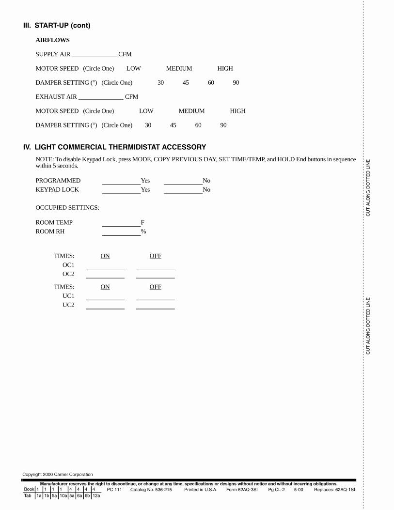
Manufacturer reserves the right to discontinue, or change at any time, specifications or designs without notice and without incurring obligations.PC 111 Catalog No. 536-215 Printed in U.S.A. Form 62AQ-3SI Pg CL-2 5-00 Replaces: 62AQ-1SI
Copyright 2000 Carrier Corporation
- -
- -
- -
- -
- -
- -
- -
- -
- -
- -
- -
- -
- -
- -
- -
- -
- -
- -
- -
- -
- -
- -
- -
- -
- -
- -
- -
- -
- -
- -
- -
- -
- -
- -
- -
- -
- -
- -
- -
- -
- -
- -
- -
- -
- -
- -
- -
- -
- -
- -
- -
- -
- -
- -
- -
- -
- -
- -
- -
- -
- -
- -
- -
- -
- -
- -
- -
- -
- -
- -
- -
- -
- -
- -
- -
- -
- -
- -
- -
- -
- -
- -
- -
- -
- -
- -
-- -
- -
- -
- -
- -
- -
- -
- -
- -
- -
C
UT
ALO
NG
DO
TT
ED
LIN
EC
UT
ALO
NG
DO
TT
ED
LIN
E
Book 1 1 1 1 4 4 4 4Tab 1a 1b 5a 10a 5a 6a 6b 12a
III. START-UP (cont)
AIRFLOWS
SUPPLY AIR CFM
MOTOR SPEED (Circle One) LOW MEDIUM HIGH
DAMPER SETTING (°) (Circle One) 30 45 60 90
EXHAUST AIR CFM
MOTOR SPEED (Circle One) LOW MEDIUM HIGH
DAMPER SETTING (°) (Circle One) 30 45 60 90
IV. LIGHT COMMERCIAL THERMIDISTAT ACCESSORY
NOTE: To disable Keypad Lock, press MODE, COPY PREVIOUS DAY, SET TIME/TEMP, and HOLD End buttons in sequencewithin 5 seconds.
OCCUPIED SETTINGS:
PROGRAMMED Yes No
KEYPAD LOCK Yes No
ROOM TEMP F
ROOM RH %
TIMES: ON OFF
OC1
OC2
TIMES: ON OFF
UC1
UC2