installation & servicing instructions - free boiler … · installation instructions e-shr...
TRANSCRIPT

INST
ALL
ATIO
N &
SER
VIC
ING
INST
RU
CTI
ON
S
8G.5
1.18
.01/
07.0
4W
e re
serv
e th
e rig
ht to
mak
e ch
ange
s
CE PIN 0063AS3538
These instructions to be retained by user.
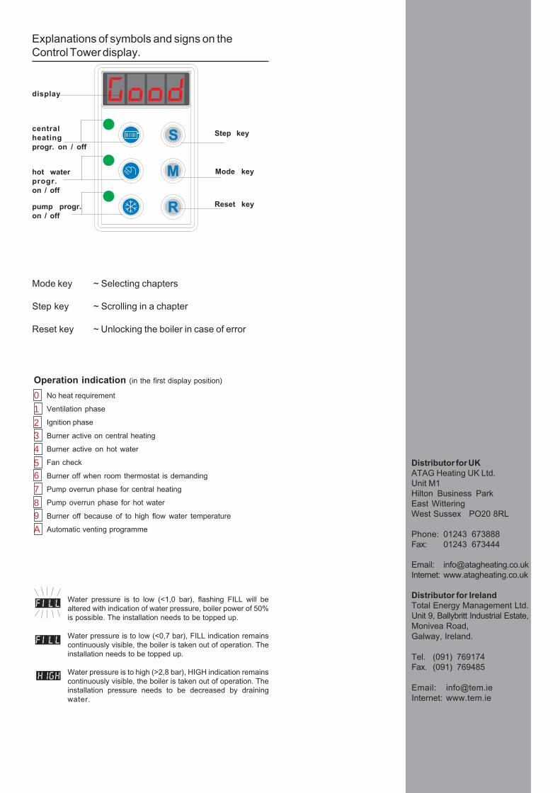
centralheatingprogr. on / off
hot waterprogr.on / off
pump progr.on / off
Reset key
Step key
display
Explanations of symbols and signs on theControl Tower display.
012
No heat requirement
Ventilation phase
Ignition phase
Burner active on central heating
Burner active on hot water
Fan check
Burner off when room thermostat is demanding
Pump overrun phase for central heating
Pump overrun phase for hot water
Burner off because of to high flow water temperature
Automatic venting programme
3456789A
Water pressure is to low (<1,0 bar), flashing FILL will bealtered with indication of water pressure, boiler power of 50%is possible. The installation needs to be topped up.
Water pressure is to low (<0,7 bar), FILL indication remainscontinuously visible, the boiler is taken out of operation. Theinstallation needs to be topped up.
Water pressure is to high (>2,8 bar), HIGH indication remainscontinuously visible, the boiler is taken out of operation. Theinstallation pressure needs to be decreased by drainingwater.
Operation indication (in the first display position)
Mode key ~ Selecting chapters
Step key ~ Scrolling in a chapter
Reset key ~ Unlocking the boiler in case of error
Mode key
Distributor for UKATAG Heating UK Ltd.Unit M1Hilton Business ParkEast WitteringWest Sussex PO20 8RL
Phone: 01243 673888Fax: 01243 673444
Email: [email protected]: www.atagheating.co.uk
Distributor for IrelandTotal Energy Management Ltd.Unit 9, Ballybritt Industrial Estate,Monivea Road,Galway, Ireland.
Tel. (091) 769174Fax. (091) 769485
Email: [email protected]: www.tem.ie

Installation instructions E-SHR series page 3
Contents1 Introduction .................................................................................................................................... 42 Regulations .................................................................................................................................... 43 Description of the appliance ........................................................................................................... 54 Scope of the supply ....................................................................................................................... 55 Mounting of the boiler ..................................................................................................................... 5
5.1 Dimensions .......................................................................................................................... 66 Connecting the boiler ..................................................................................................................... 8
6.1 Central heating system ........................................................................................................ 96.2 Expansion vessel ............................................................................................................... 106.3 Underfloor heating systems(plastic pipes) .......................................................................... 106.4 Gas connection .................................................................................................................. 106.5 Hot water supply E-SHR 24T and 35T ................................................................................ 106.6 Hot water supply E-SHR 15 and 24 .................................................................................... 116.7 Condensation drain pipe ..................................................................................................... 116.8 Flue gas exhaust system and air supply system ............................................................... 116.9 Air supply .......................................................................................................................... 12
7 Electrical connection .................................................................................................................... 138 Boiler controls .............................................................................................................................. 15
8.1 Explanation of the function keys ........................................................................................ 159 Filling and venting the boiler and installation ................................................................................. 16
9.1 Central heating system ...................................................................................................... 169.2 Hot water supply ................................................................................................................ 16
10 Commissioning the boiler ............................................................................................................ 1710.1 Central Heating system...................................................................................................... 1710.2 Hot water supply ................................................................................................................ 1710.3 Adjustments ...................................................................................................................... 17
11 Isolating the boiler ........................................................................................................................ 2012 Commissioning ............................................................................................................................ 21
12.1 Checking for contamination ................................................................................................ 2112.2 Checking the CO2 .............................................................................................................. 22
13 Maintenance ................................................................................................................................ 2313.1 The frequency of maintenance ............................................................................................ 2313.2 Maintenance activities ........................................................................................................ 2313.3 Further checks ................................................................................................................... 23
14 Technical specifications ............................................................................................................... 2415 Diagram showing various parts of the boiler .................................................................................. 2516 Example diagrams for connecting the boiler ................................................................................. 27
16.1 Radiator installation without thermostat valves.................................................................... 2716.2 Radiator installation with thermostat valves only ................................................................. 28
17 Error indication ............................................................................................................................. 2918 CE-Certificate United Kingdom ..................................................................................................... 3019 CE-Certificate Ireland ................................................................................................................... 31
The boiler should only be installed by a Competent Gas Installer.Work on the boiler must be carried out by a competent person, (Ref: Gas Safety Installationand Use ) using correctly calibrated instruments with current test certification.
����������������������� ��������������
� ����������
����������������� ����������������������������������������� ������������������������������������������������������ ����� ����� ������ ��������������� �������� ���������� ��� ����� ������ ��� ��������� ������ �
������ ����������� ��� ����� � � ��� ���� ��� ��� ���������� �������������������� ��� ����������������������������� ����������������������� ������������������������������������������ !������������ ��������������������������� ���� ��� � !����� ��� �������������� "�������������������������������� � �����������������������������������������������������������������������������#��������������$����������������� �������!���� ������ ����������������������������������������%�������� &����� ����� ���!��� ���� ����� ��� ����� ����� ���� �����������������������
������������������ �������������� �������������� ��������������������� ��������������� ��������������� �������� �����������
'���������������� � �������� ������������������������������ ������������������������!����� �������������������������� ������������� � ���������������(������������� �������� ��)��������������������
*�� ����������� ��� ���� ������������� ���� ��������� ������������������������������������� ��������������������$����������������������������������������$��� ��� ��������������� �������������� �$������������������$��������$������������������ ������ ��������� ���������!��������������� �����������!������������ ����� ������������������������������������$������������������������������������ ���������+����������,� �-������'�����.����������,� ������� �������� ������������������ � ��� ������� �������������� ��� �������� � � ��������������
� � ��������
��������� ��������������������������������������������������������������(
,������������� �/��������������"������0��������������� ����1����������������������������� ������������� ���������������������������.���������*/����� �������� ����� �����������������"�����/����������&������������������������������������� ���� �������������
���� ����������������!����������������������������������������� ��������������� ��������������''�/����������������� ����"��� � ��0"������ �������� �����1�/����������/������������ ������� ���������,�������������������� ���������+�������� �"������/���������
�������2 ��������� � �3452 6�������������������������
���� ������ '���������� �����$� /������������� ��������� � ������ ���������������� ����� �����������!����� ������� ���������������������"��� � ��
���������7����������������������� ������������� ������������� ���� ����������� �������� ������������������������������.�����.����������������������������������$���������� ������!�� ������������������������
���������7����� ��� �� ������� �������� ���� ���� ������������������� ����� �������������������������������������� ����� ���� ��� ������ ������������� ������������������������������������������������������������������� �
*���!����������� �����������������(2 ���� �$� ��� ���� ���� ���� ��$�� ������ ��� �� ���!��������
2 ����������������!����������������� �������������������)������������������� ������������������ 8��������0�����������49��� �451�
2 :�!������ ������������������������������������������������������ ���� ����
���� ��� ���� ����� ���� ���$�� ��� ����������� ������������������������������� �2�������� ����(2 "��� � ��������������;2 �����������������;2 ����������������������������������������������;2 ������������������$�����������%������$�������������
��$�� ����� ��� ���� ����� ���� ���� ������������ �� 8�������������� � (2 ���� ���� ���� ��� ����� ��� �������� ���� ���������!�����;�����������������������%��������!����������� ������ �� � ���� ������ ���� ����������� ��'����������������������������������������� ����� ��������������!������
���������� ������������ �� ����� ����������������� ������ ���� ������������� ��� ���� ������� �������������������� ��������� ���������!�
���������� ������������ �� ����� ������������������������������ ������������ ��������������������"#!�
Installation instructions E-SHR series page 5
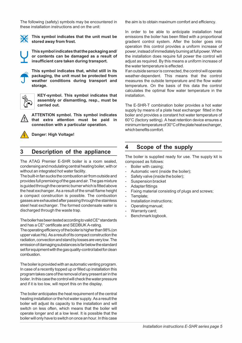
The following (safety) symbols may be encountered inthese installation instructions and on the unit:
This symbol indicates that the unit must bestored away from frost.
This symbol indicates that the packaging and/or contents can be damaged as a result ofinsufficient care taken during transport.
This symbol indicates that, whilst still in itspackaging, the unit must be protected fromweather conditions during transport andstorage.
KEY-symbol. This symbol indicates thatassembly or dismantling, resp., must becarried out.
ATTENTION symbol. This symbol indicatesthat extra attention must be paid inconnection with a particular operation.
Danger: High Voltage!
3 Description of the applianceThe ATAG Premier E-SHR boiler is a room sealed,condensing and modulating central heating boiler, with orwithout an integrated hot water facility.The built-in fan sucks the combustion air from outside andprovides full premixing of the gas and air. The gas mixtureis guided through the ceramic burner which is fitted abovethe heat exchanger. As a result of the small flame heighta compact construction is possible. The combustiongasses are exhausted after passing through the stainlesssteel heat exchanger. The formed condensate water isdischarged through the waste trap.
The boiler has been tested according to valid CE* standardsand has a CE* certificate and SEDBUK A-rating.The operating efficiency of the boiler is higher than 98% (onupper value Hs). As a result of its compact construction theradiation, convection and stand by losses are very low. Theemission of damaging substances is far below the standardset for equipment with the gas quality-control label for cleancombustion.
The boiler is provided with an automatic venting program.In case of a recently topped up or filled up installation thisprogram takes care of the removal of any present air in theboiler. In this case the control will check the water pressureand if it is too low, will report this on the display.
The boiler anticipates the heat requirement of the centralheating installation or the hot water supply. As a result theboiler will adjust its capacity to the installation and willswitch on less often, which means that the boiler willoperate longer and at a low level. It is possible that theboiler will only have to switch on once an hour. In this case
the aim is to obtain maximum comfort and efficiency.
In order to be able to anticipate installation heatemissions the boiler has been fitted with a proportionalgradient control system. After the boiler goes intooperation this control provides a uniform increase ofpower, instead of immediately burning at full power. Whenthe installation does require full power the control willadjust as required. By this means a uniform increase ofthe water temperature is effected.If an outside sensor is connected, the control will operateweather-dependent. This means that the controlmeasures the outside temperature and the flow watertemperature. On the basis of this data the controlcalculates the optimal flow water temperature in theinstallation.
The E-SHR-T combination boiler provides a hot watersupply by means of a plate heat exchanger fitted in theboiler and provides a constant hot water temperature of60°C (factory setting). A heat retention device ensures aminimum temperature of 30°C of the plate heat exchanger,which benefits comfort.
4 Scope of the supplyThe boiler is supplied ready for use. The supply kit iscomposed as follows:- Boiler with casing;- Automatic vent (inside the boiler);- Safety valve (inside the boiler);- Suspension bracket- Adapter fittings- Fixing material consisting of plugs and screws;- Template;- Installation instructions;- Operating manual;- Warranty card;- Benchmark logbook.
Installation instructions E-SHR series page 6
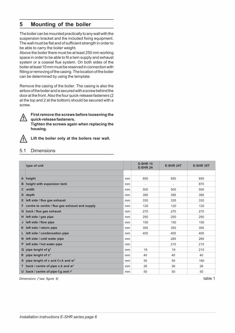
5.1 Dimensions
5 Mounting of the boilerThe boiler can be mounted practically to any wall with thesuspension bracket and the included fixing equipment.The wall must be flat and of sufficient strength in order tobe able to carry the boiler weight.Above the boiler there must be at least 250 mm workingspace in order to be able to fit a twin supply and exhaustsystem or a coaxial flue system. On both sides of theboiler at least 10 mm must be reserved in connection withfitting or removing of the casing. The location of the boilercan be determined by using the template.
Remove the casing of the boiler. The casing is also theairbox of the boiler and is secured with a screw behind thedoor at the front. Also the four quick-release fasteners (2at the top and 2 at the bottom) should be secured with ascrew.
First remove the screws before loosening thequick-release fasteners.Tighten the screws again when replacing thehousing.
Lift the boiler only at the boilers rear wall.
Dimensions (*see figure 4) table 1
tinufoepyt 51RHS-E42RHS-E T42RHS-E T53RHS-E
A thgieh mm 056 056 056B thgieh knatnoisnapxehtiw mm - - 078C htdiw mm 005 005 005D htped mm 593 593 593E tsuahxesageulf/edistfel mm 533 533 533F ylppusdnatsuahxesageulf/ertnecotertnec mm 021 021 021G tsuahxesageulf/kcab mm 072 072 072H epipsag/edistfel mm 052 052 052J epipwolf/edistfel mm 051 051 051K epipnruter/edistfel mm 053 053 053L epipnoitasnednoc/edistfel mm 504 504 504N epipretawdloc/edistfel mm 582 582P epipretawtoh/edistfel mm 512 512Q *gfothgnelepip mm 91 91 512R *cfothgnelepip mm 04 04 04S *wdnak;r;fdnacfothgnelepip mm 05 05 061T cepipfoertnec/kcab wdnak; * mm 62 62 62U *rdnag;fepipfoertnec/kcab mm 05 05 05

Installation instructions E-SHR series page 7
wal
lceiling
minimumof 250 mm
minimumof 10 mm
dimensions (in mm) figure 2
D
F
TU
C
R
K
S
JP
HN
G
Q
L
E
B A
dimensions of fastening and supporting positions (in mm) figure 3
54
332
619,
5
337supporting point
5222
0
Two points are located on the back of the boiler, whichcan be used in situations, in which the boiler is beingsuspended on a frame. In addition, the dimensions ofthe drilling holes for fastening the boiler are shown. Thedimensions of the drilling holes are also shown on thetemplate.
Installation instructions E-SHR series page 8
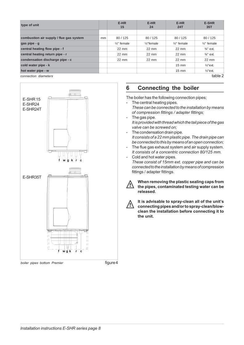
6 Connecting the boilerThe boiler has the following connection pipes;- The central heating pipes.
These can be connected to the installation by meansof compression fittings / adapter fittings;
- The gas pipe.It is provided with thread which the tail piece of the gasvalve can be screwed on;
- The condensation drain pipe.It consists of a 22 mm plastic pipe. The drain pipe canbe connected to this by means of an open connection;
- The flue gas exhaust system and air supply system.It consists of a concentric connection 80/125 mm.
- Cold and hot water pipes.These consist of 15mm ext. copper pipe and can beconnected to the installation by means of compressionfittings / adapter fittings.
When removing the plastic sealing caps fromthe pipes, contaminated testing water can bereleased.
It is advisable to spray-clean all of the unit’sconnecting pipes and/or to spray-clean/blow-clean the installation before connecting it tothe unit.
connection diameters table 2
f w g k r c
boiler pipes bottom Premier figure 4
tinufoepytRH-E
51RH-E
42RH-E
T42RHS-E
T53
metsyssageulf/ylppusrianoitsubmoc mm 521/08 521/08 521/08 521/08
g-epipsag elamef"½ elamef"½ elamef"½ elamef"½
f-epipwolfgnitaehlartnec mm22 mm22 mm22 .txe"¾
r-epipnrutergnitaehlartnec mm22 mm22 mm22 .txe"¾
c-epipegrahcsidnoitasnednoc mm22 mm22 mm22 mm22
k-epipretawdloc mm51 .txe"½
w-epipretawtoh mm51 .txe"½
f w g k r c
E-SHR 15E-SHR24E-SHR24T
E-SHR35T

Installation instructions E-SHR series page 9
6.1 Central heating system
The boiler pipes can be connected to the installation bymeans of compression fittings. Reducers should be usedfor connecting to thick-walled pipe (welded or threaded).
The boiler has a self-adjusting and self-protecting controlsystem for the load capacity. By this means the temperaturedifference between the flow and return water is checked. Thecirculation pump will be able to supply the given waterdisplacement with an installation resistance of up to 18 kPa,for this see table 3.
If the capacity of the boiler pump is insufficient, an extraexternal pump can be installed in series with the boiler.The electrical side of this external circulation pump canbe connected in the Control Tower, by which means thispump switches at the same times as the boiler pump.The maximum absorbed current consumption of theexternal circulation pump may be 230 W (1 Amp).
If the installation resistance is higher than the stated valuethe load will be adjusted until an acceptable temperaturedifference between flow and return water has beenobtained. If, after this, the temperature difference remainstoo much then the boiler will switch itself off and wait untilan acceptable temperature has arisen.If an unacceptable temperature is detected, then thecontrol will repeatedly try to achieve water flow, and if thisdoes not work then the boiler will switch off.
available water flow at full load table 3
external installation pump in series figure 6
tinufoepytpmuP
epyt
etarwolfretaw� C°02T
elbissimrepnoitallatsniecnatsiser
nim/l h/l aPk rabm
51RHS-E 05-02SPU 3,01 026 33 033
42RHS-E 05-02SPU 1,51 089 02 002
T42RHS-E 05-02SPU 1,51 089 02 002
T53RHS-E 06-02PU 22 4231 81 081
pump index lines graph 1Q(m³/h)
Pumpcharacteristic UP 20-60 24T
/35T
15/
24Pumpcharacteristic
UPS 20-50 (pos. 1)
H(m)
As standard the boiler is provided with a water filter in thereturn pipe of the boiler. With this, possible contaminationof the central heating water is prevented from ending upin the boiler. The boiler is also provided with an internalsafety valve set at 3 bar. This is connected by means ofa combination waste to the condensate discharge.
If all, or a large number of radiators are providedwith thermostatic radiator valves it is advisable touse a pressure difference control (bypass) in order toprevent flow problems in the installation.
The boiler is designed to be used on sealedsystem only.
Additives in the installation water are onlypermitted in consultation with the countrydistributor.
7
6
5
4
3
2
1
00 0,5 1 1,5 2 2,5
Pumpcharacteristic
UPS 20-50 (pos. 2)
Installation instructions E-SHR series page 10
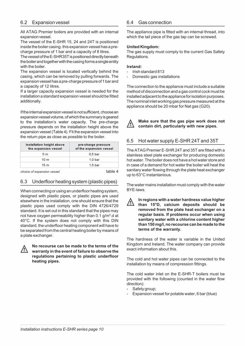
6.2 Expansion vessel
All ATAG Premier boilers are provided with an internalexpansion vessel.The vessel of the E-SHR 15, 24 and 24T is positionedinside the boiler casing. this expansion vessel has a pre-charge pressure of 1 bar and a capacity of 8 litres.The vessel of the E-SHR35T is positioned directly beneaththe boiler and together with the casing forms a single entitywith the boiler.The expansion vessel is located vertically behind thecasing, which can be removed by pulling forwards. Theexpansion vessel has a pre-charge pressure of 1 bar anda capacity of 12 litres.If a larger capacity expansion vessel is needed for theinstallation a standard expansion vessel should be fittedadditionally.
If the internal expansion vessel is not sufficient, choose anexpansion vessel volume, of which the summary is gearedto the installation’s water capacity. The pre-chargepressure depends on the installation height above theexpansion vessel (Table 4). Fit the expansion vessel intothe return pipe as close as possible to the boiler.
6.4 Gas connection
The appliance pipe is fitted with an internal thread, intowhich the tail piece of the gas tap can be screwed.
United Kingdom:The gas supply must comply to the current Gas SafetyRegulations.
Ireland:- Irish standard 813- Domestic gas installations
The connection to the appliance must include a suitablemethod of disconnection and a gas control cock must beinstalled adjacent to the appliance for isolation purposes.The nominal inlet working gas pressure measured at theappliance should be 20 mbar for Nat gas (G20).
Make sure that the gas pipe work does notcontain dirt, particularly with new pipes.
6.5 Hot water supply E-SHR 24T and 35T
The ATAG Premier E-SHR 24T and 35T are fitted with astainless steel plate exchanger for producing domestichot water. The boiler does not have a hot water store andin case of a demand for hot water the boiler will heat thesanitary water flowing through the plate heat exchangerup to 63°C instantanious.
The water mains installation must comply with the waterBYE-laws.
In regions with a water hardness value higherthan 15°D, calcium deposits should beremoved from the plate heat exchanger on aregular basis. If problems occur when usingsanitary water with a chlorine content higherthan 150 mg/l, no recourse can be made to theterms of the warranty.
The hardness of the water is variable in the UnitedKingdom and Ireland. The water company can provideexact information about this.
The cold and hot water pipes can be connected to theinstallation by means of compression fittings.
The cold water inlet on the E-SHR-T boilers must beprovided with the following (counted in the water flowdirection):- Safety group;- Expansion vessel for potable water, 6 bar (blue)
6.3 Underfloor heating system (plastic pipes)
When connecting or using an underfloor heating system,designed with plastic pipes, or plastic pipes are usedelsewhere in the installation, one should ensure that theplastic pipes used comply with the DIN 4726/4729standard. It is set out in this standard that the pipes maynot have oxygen permeability higher than 0.1 g/m³.d at40°C. If the system does not comply with this DINstandard, the underfloor heating component will have tobe separated from the central heating boiler by means ofa plate exchanger.
No recourse can be made to the terms of thewarranty in the event of failure to observe theregulations pertaining to plastic underfloorheating pipes.
choice of expansion vessel table 4
��������������������������� �����
������� ��������� ��������� �������
�� ������
��� ������
��� ������
Installation instructions E-SHR series page 11
6.6 Hot water supply E-SHR 15 and 24
Depending of the comfort preferences different externalhot water cylinders can be connected to E-SHR 15 and24 solo boiler. The choice of the cylinder depends on thecoil output. The coil output must be compatible with theboiler output. The E-SHR 15 and 24 are provided with aninternal DHW control. The electrical connection can bemade on the connection terminal in the Control Tower.See the wiring diagram on page 13 and 14.
6.7 Condensation drain pipe
The collective condensation drain pipe should beconnected to the drain by means of an open connection(Tundish Break). Removing the possibility of foul draingases and water backing up into the boiler. The drainconnection should have a minimum diameter of 25 mm.
The following components are connected to the combi-nation condensation drain pipe:- Condensation discharge;- Safety valve;
Draining of the condensation water to theexternal rain guttering is not permitted inview of the danger of freezing.
Before putting the boiler into operation fill thesiphon with 300 ml of water.
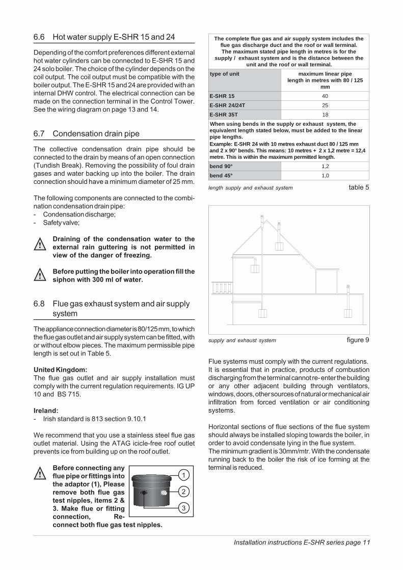
6.8 Flue gas exhaust system and air supplysystem
The appliance connection diameter is 80/125 mm, to whichthe flue gas outlet and air supply system can be fitted, withor without elbow pieces. The maximum permissible pipelength is set out in Table 5.
United Kingdom:The flue gas outlet and air supply installation mustcomply with the current regulation requirements. IG UP10 and BS 715.
Ireland:- Irish standard is 813 section 9.10.1
We recommend that you use a stainless steel flue gasoutlet material. Using the ATAG icicle-free roof outletprevents ice from building up on the roof outlet.
Before connecting anyflue pipe or fittings intothe adaptor (1), Pleaseremove both flue gastest nipples, items 2 &3. Make flue or fittingconnection, Re-connect both flue gas test nipples.
Flue systems must comply with the current regulations.It is essential that in practice, products of combustiondischarging from the terminal cannot re- enter the buildingor any other adjacent building through ventilators,windows, doors, other sources of natural or mechanical airinfiltration from forced ventilation or air conditioningsystems.
Horizontal sections of flue sections of the flue systemshould always be installed sloping towards the boiler, inorder to avoid condensate lying in the flue system.The minimum gradient is 30mm/mtr. With the condensaterunning back to the boiler the risk of ice forming at theterminal is reduced.
supply and exhaust system figure 9
length supply and exhaust system table 5
ehtsedulcnimetsysylppusriadnasageulfetelpmocehT.lanimretllawrofoorehtdnatcudegrahcsidsageulf
ehtrofsisertemnihtgnelepipdetatsmumixamehTehtneewtebecnatsidehtsidnametsystsuahxe/ylppus
.lanimretllawrofoorehtdnatinu
tinufoepyt epipraenilmumixam521/08htiwsertemnihtgnel
mm
51RHS-E 04
T42/42RHS-E 52
T53RHS-E 81
eht,metsystsuahxeroylppusehtnisdnebgnisunehWraenilehtotdeddaebtsum,wolebdetatshtgneltnelaviuqe
.shtgnelepipmm521/08tcudtsuahxesertem01htiw42RHS-E:elpmaxE
4,21=ertem2,1x2+sertem01:snaemsihT.sdneb°09x2dna.htgneldettimrepmumixamehtnihtiwsisihT.ertem
°09dneb 2,1
°54dneb 0,1
1
2
3
Installation instructions E-SHR series page 12
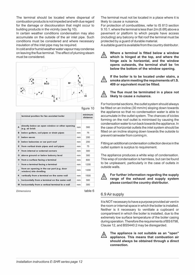
The terminal should be located where dispersal ofcombustion products is not impeded and with due regardfor the damage or discolouration that might occur tobuilding products in the vicinity (see fig 10).In certain weather conditions condensation may alsoaccumulate on the outside of the air inlet pipe. Suchconditions must be considered and where necessaryinsulation of the inlet pipe may be required.In cold and/or humid weather water vapour may condenseon leaving the flue terminal. The effect of pluming steammust be considered.
The terminal must not be located in a place where it islikely to cause a nuisance.For protection of combustibles, refer to IS 813 section9.10.1. where the terminal is less than 2m (6.6ft) above apavement or platform to which people have access(including) any balcony or flat roof the terminal must beprotected by a guard of durable material.A suitable guard is available from the country distributor.
Where a terminal is fitted below a windowwhich is hinged at the top, and where thehinge axis is horizontal, and the windowopens outwards, the terminal shall be 1mbelow the bottom of the window opening.
If the boiler is to be located under stairs, asmoke alarm meeting the requirements of I.S.409 or equivalent must be fitted.
The flue must be terminated in a place notlikely to cause a nuisance.
For horizontal sections, the outlet system should alwaysbe fitted on an incline (30 mm/m) sloping down towardsthe appliance so that no condensation water is able toaccumulate in the outlet system. The chances of iciclesforming on the roof outlet is minimised by causing thecondensation water to run back towards the appliance. Inthe case of horizontal outlets the inlet system should befitted on an incline sloping down towards the outside toprevent rainwater from coming in.
Fitting an additional condensation collection device in theoutlet system is surplus to requirement.
The appliance produces a white wisp of condensation.This wisp of condensation is harmless, but can be foundto be unpleasant, particularly in the case of outlets inoutside walls.
For further information regarding the supplyrange of the exhaust and supply systemplease contact the country distributor.
6.9 Air supply
It is NOT necessary to have a purpose provided air vent inthe room or internal space in which the boiler is installed.Neither is it necessary to ventilate a cupboard orcompartment in which the boiler is installed, due to theextremely low surface temperature of the boiler casingduring operation. Therefore the requirements of BS 6798,Clause 12, and BS5440:2 may be disregarded.
The appliance is not suitable as an "open"appliance. This means that combustion airshould always be obtained through a directconnection.
figure 10
��������������������� ����������������
��� ������������� ��������������
������������� ��
� �� ������� ���������������� �� �
� ���������� �� ���
� ������� ����������������� �� ���
�� ������� �������������� �� �
! ������������������������ �� ��
" ���������������������������� �� ��
# ����������������������� �� ���
$ ���������������������� �� ����
%������������ �������� ������
��������&������ ����
' �������������������������������� �� ����
( �����������������������������)��� �� ��
* �������������������������������)��� �� ��
Dimensions table 6
Installation instructions E-SHR series page 13
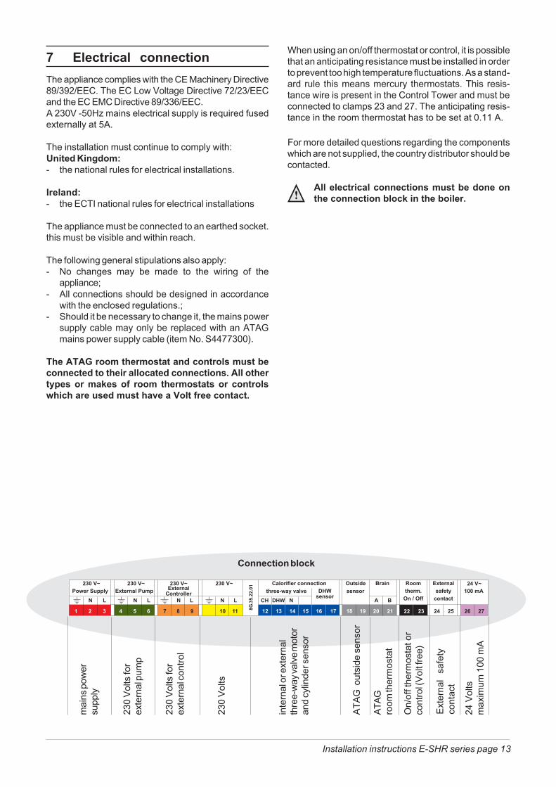
7 Electrical connectionThe appliance complies with the CE Machinery Directive89/392/EEC. The EC Low Voltage Directive 72/23/EECand the EC EMC Directive 89/336/EEC.A 230V -50Hz mains electrical supply is required fusedexternally at 5A.
The installation must continue to comply with:United Kingdom:- the national rules for electrical installations.
Ireland:- the ECTI national rules for electrical installations
The appliance must be connected to an earthed socket.this must be visible and within reach.
The following general stipulations also apply:- No changes may be made to the wiring of the
appliance;- All connections should be designed in accordance
with the enclosed regulations.;- Should it be necessary to change it, the mains power
supply cable may only be replaced with an ATAGmains power supply cable (item No. S4477300).
The ATAG room thermostat and controls must beconnected to their allocated connections. All othertypes or makes of room thermostats or controlswhich are used must have a Volt free contact.
230
Volts
for
exte
rnal
pum
p
mai
ns p
ower
supp
ly
230
Volts
for
exte
rnal
cont
rol
230
Volts
inte
rnal
or e
xter
nal
thre
e-w
ay va
lve m
otor
and
cylin
der s
enso
r
ATAG
room
ther
mos
tat
On/
off t
herm
osta
t or
cont
rol (
Volt f
ree)
Connection block
ATAG
out
side
sen
sor
Exte
rnal
sa
fety
cont
act
24 V
olts
max
imum
100
mA
When using an on/off thermostat or control, it is possiblethat an anticipating resistance must be installed in orderto prevent too high temperature fluctuations. As a stand-ard rule this means mercury thermostats. This resis-tance wire is present in the Control Tower and must beconnected to clamps 23 and 27. The anticipating resis-tance in the room thermostat has to be set at 0.11 A.
For more detailed questions regarding the componentswhich are not supplied, the country distributor should becontacted.
All electrical connections must be done onthe connection block in the boiler.
Installation instructions E-SHR series page 14
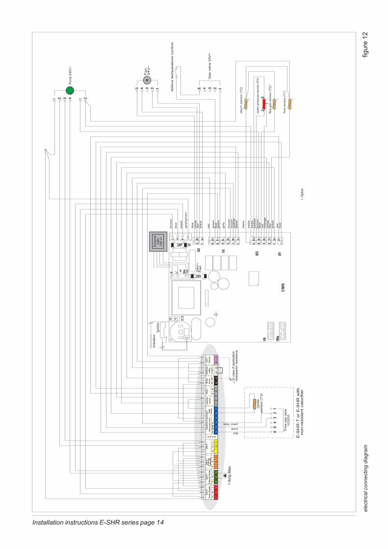
elec
trica
l con
nect
ing
diag
ram
fig
ure
12

Installation instructions E-SHR series page 15
8 Boiler controlsThe boiler is provided with a fully automatic microprocessorcontrol. This control simplifies operation by undertaking allmajor control functions. Initially when power to the unit isswitched on it will remain on standby. The control paneldisplay will show the relevant state. The various parame-ters can be called up in two ways:
The state.In this state the display will show during all normaloperating functions of the appliance. Should a faultdevelop this will be shown on the display.
The technical read out.Start from the state by pressing the Step key for5 seconds. Returning from this to the display isdone in the same way. From the technical read out a moreextensive read out can be obtained e.g. the boiler flowtemperature and the water pressure in the central heatingsystem.
When the system has been filled and the automatic ventingprogram starts, when a program has been selected, theprogram takes 15 minutes and stops automatically. Afterthis the unit will function normally.
On a call for heating or hot water the control system willselect the required water control temperature. This watertemperature is called the T-set value. On a call for centralheating the boiler ignites first at low input. The input is thenchanged slowly to match the load required. The boileroperates in this way to avoid excessive water noises andtemperature overshoot. On a call for hot water supply theT-set value of central heating return water temperature ismonitored. Depending on the amount of sanitary waterwhich is withdrawn from the DHW facility, the centralheating return water temperature, from which the input isadjusted, will vary.
8.1 Explanation of the function keys
Key functions from the and the extensiveindication are:
- Central Heating program key, see chapter 9.1;- Hot Water program key, see chapter 9.2;- PC program key, adjusts the pump to continuous
water circulation in the central heating system, oraccording to the pump overrun times on the relevantprograms;
- Step key, after briefly pressing, the water pressurecan be retrieved and pages per chapter can beretrieved. After pressing for 5 seconds it switches from
indication to technical indication and the otherway round;
- Mode key, after briefly pressing, a selection of thedata chapters can be retrieved. After pressing for 5seconds it is possible to enter the code as describedin chapter 9.3;
- Reset key, after briefly pressing, for:unlocking errors;ending the access code;ending the automatic venting program, only when theaccess code is entered and the reset key is pressedbriefly.After pressing for 5 seconds an operating stop ismade, for example, for activating the automaticventing program.
Other key functions from the other indications are:
- Central Heating key then has the + function;- Hot Water key then has the - function;- PC key then has the store function, which means
that by means of this key a modified setting isconfirmed;
- Step key for scrolling in a data chapter.

Installation instructions E-SHR series page 16
9 Filling and venting the boilerand installation
Filling of the system is carried out in the normal way. Inorder to read out the central heating water pressure theelectrical supply must be switched on.
The circulation pump will not begin to operate as long asthe operating lamps are off. The control display will showa indication, which means that the control issignalling insufficient water pressure. If the installation isfilled and the water pressure rises then the water pressurewill automatically be shown with an alternating text.If the water pressure rises to above 1.5 bar then after a short“stop” text the indication will appear, which meansthe water pressure is sufficient and the boiler is ready foroperation.In order to be able to read out a constant water pressure theStep key should be pressed in and in order to obtain aconstant readout the Step key should be pressedbriefly again.
If the water pressure in the boiler becomes to high (>2,8bar) a text appears, by which means the burner isswitched off. After draining the water from the installation,by which means the water pressure arrives below 2,5 bar,the text disappears and the burner is activated.
In order to go from a read-out to a technical readout the Step key should be pressed for 5 seconds.This read-out can be selected if the user requires atechnical read out. In order to return to the read-out the Step key must be pressed again for 5 seconds.
9.1 Central heating system
To fill the central heating system use the filling and drainvalve provided.
Fill the system as follows.- Turn on the electrical supply and leave the operational
lamps off;- Connect the mains filling loop (not supplied);- Open the cold water supply tap on the filling loop and
allow the system to fill slowly;- The boiler has an automatic vent which removes the air
which is present;- Bring the installation pressure up to between 1.5 and
2.0 bar after all radiators and pipes have been vented;- Close the mains filling loops main inlet tap, remove
filling loop and cap supplies;- Activate the automatic venting program by pressing
the pump key which means the pump lamp will beilluminated. Allow the control to finish its ventingprogram. The pump will circulate a number of timesaround the boiler as well as the central heatinginstallation.
Also, if a three-way valve is present, this will beadjusted to the boiler and central heating installationa number of times. The pump will be stopped regularlyin order to allow possible present air to escape.
- Check the water pressure and if required top up. Theworking pressure in the installation should be between1.5 and 2 bar in cold state.
- After finishing the automatic venting program the key can be switched off again.
It can take several days before all the air isremoved from a freshly filled installation.Especially in the first week noises can beheard which indicate the presence of air. Theautomatic air vent in the boiler will eventuallyremove the air, from the system during thisperiod the water pressure in the system maybe deduced, if so it would be necessary to topup the system with water to the nominalpressure (1.5-2.0 bar) when cold.
9.2 Hot water supply
Open the main cold water supply valve to the DHW facilityand open the safety group.
Vent the plate exchanger and the hot water installation byopening a hot water tap. Leave the tap open for as long asrequired until all air has disappeared from the cylinder andthe pipes and only water is flowing from the tap.

Installation instructions E-SHR series page 17
10 Commissioning the boilerBefore the boiler is fired, ensure that the boiler and thesystem are well vented and free of air. Purge the gas linebetween the gas meter and the boiler and carry out a gassoundness test as specified in the current Gas SafetyRegulations.The boiler does not require adjustment of the burnerpressure and air quantity because it is self adjusting andis factory set at the correct value.
10.1 Central Heating system
Provided there is a heat requirement from the thermostator control, the central heating program will be put intooperation by means of the key (central heatingprogram). The circulation pump will start circulating andthe boiler will start the burner.
10.2 Hot water supply
Provided there is a heat requirement from the cylinder thehot water program will be put into operation by means ofthe key (hot water program).
10.3 Adjustments
In the Control Tower a number of adjustments can bemade. These adjustments can be fed in easily by meansof the keys on the boiler. However, a distinction is madebetween adjustments which are done by the user andadjustments done by the installer.At users level adjustments can only be made from thetechnical read-out in other words from the display read-out with the operating function and the water temperature.Adjustments can not be made from the indication.
The next two chapters are accessible after pressing theMode key:Chapter 1 The normal operating functions such as the simple
read out or the technical with the read out.
Chapter 2 The chapter in which adjustments can be made.
����������������������� ���������������
����� 8����������� ������������� ���!������������������������ ��!��� ���� ���� �� ������� ��������������������� ������ ��������������� ���� ���������� ����������� ������������������� �����&������� ��������� 2������������"����$������<������ ������� ������������������������� ����� ������������� ���������� ����3������ ���� ����� �������������9������ ���������������������.� ��$����������� �����������=� 8�������>����������� ������� ������������������)�� �����������������"����$�������������� 8������������������������ ���� 8���������������)� �!������������� ������������������?@%������?2%�$������������������������� ������������ ��� ��������"����$���
$�%&%'�(���)����������*�������������+ ����������������������������,���� -� ���� .� ��� ���������� ����� �����,�������� ����� ���� (���)� ���� ����� ,��������������,������(���)�������������������������,����+ ������*���������������������,��-�����,���/ ������,������(���)������ �������������� ����� ����� ��� ���� (���)������������������������(���)�������������������������� ���
���� �� ��������������� ��� ����� 8����������������������!����������������� �������������� ���������&���������������� ����������������!����������� ����
7��������.� ��$������<������ ���������)�������� �������� ��������� ��������������������� ������������������������@�������2�$��������� �
���������� ����������������������"����$�������� ������������ �������������� �����������������!����������������� �
������)���������������� ������������������.� ��$��(
�������5������������ ��������������������������!� �
�������A��������������� ������ 8����������������� ������!�����������
�������<��������������� �������� ���������������!� �
����� �������� � ���������� ��������B
stnemtsujdaretemarapresUpetS noitpircsed yrotcaf egnar1 gnitaehlartnec.pmetretawwolfmumixam C°58 C°09-022 metsysgnitaehlartnecfoepyt 10 4-1
10 srotcevnoc;gnitaehria;srotaidarretawwolfxamT C°58 .motuaenilgnitaehrotcafK 3.2 .motua
tneidarg nim/C°5 .motualaitnereffidraeg C°6 .motua
20 lanoitiddasagnitaehroolfrednurosaeraecafrusegralhtiwsrotaidargnitaeh
retawwolfxamT C°07 .motuaenilgnitaehrotcafK 8.1 .motua
tneidarg nim/C°5 .motualaitnereffidraeg C°5 .motua
30 gnitaehlanoitiddasasrotaidarhtiwgnitaehroolfrednuretawwolfxamT C°06 .motuaenilgnitaehrotcafK 5.1 .motua
tneidarg nim/C°4 .motualaitnereffidraeg C°4 .motua
40 gnitaehroolfrednullufretawwolfxamT C°05 .motuaenilgnitaehrotcafK 0.1 .motua
tneidarg nim/C°3 .motualaitnereffidraeg C°3 .motua
*01 erutarepmetyadenilgnitaehtnemtsujdaenif 0 5tot5-*11 erutarepmetthginenilgnitaehtnemtsujdaenif 0 5tot5-32 erutarepmetytefastsorf C°3- C°01tot02-
13 rednilyclanoitiddafoerutarepmetffo-hctiwsreliobRH-Shtiw C°36 C°08-04
* eeS tatsomrehtQniarBGATA
������������������ �����9
������������������� ���
����
��
���
����
�� �
��
����������������������� ���������������
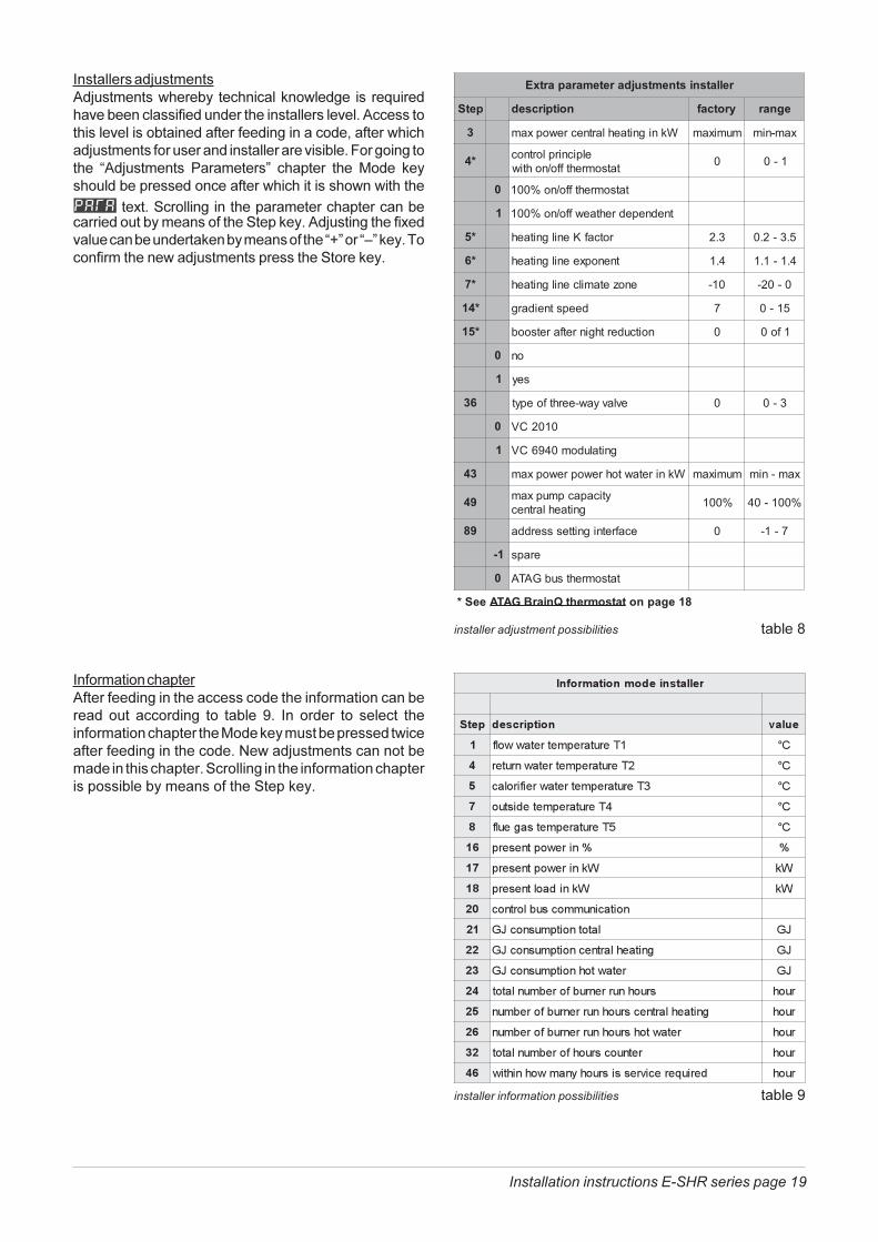
����������� 8�������� 8�������� ����������������$�� �� �������#�� ��!���������������� �� ������������������!��������������������!������������� ��������� ����������� �������� ����� 8���������������� �������������!��������&�������������� =� 8�������� 7�������>� ������� ����.� �� $������ ��������� ����������� �������������� �� �������
���)���"���������������������������������������� ��������������������"����$����� 8������������)� !������������ ���$�������������������=@>���=C>�$������������������� �� 8�����������������"����$���
������������������ ���������� ������3
rellatsnistnemtsujdaretemarapartxE
petS noitpircsed yrotcaf egnar
3 Wknignitaehlartnecrewopxam mumixam xam-nim
*4 elpicnirplortnoctatsomrehtffo/nohtiw 0 1-0
0 tatsomrehtffo/no%001
1 tnednepedrehtaewffo/no%001
*5 rotcafKenilgnitaeh 3.2 5.3-2.0
*6 tnenopxeenilgnitaeh 4.1 4.1-1.1
*7 enozetamilcenilgnitaeh 01- 0-02-
*41 deepstneidarg 7 51-0
*51 noitcuderthginretfaretsoob 0 1fo0
0 on
1 sey
63 evlavyaw-eerhtfoepyt 0 3-0
0 0102CV
1 gnitaludom0496CV
34 Wkniretawtohrewoprewopxam mumixam xam-nim
94 yticapacpmupxamgnitaehlartnec %001 %001-04
98 ecafretnignittessserdda 0 7-1-
1- eraps
0 tatsomrehtsubGATA
eeS* tatsomrehtQniarBGATA 81egapno
������������������������� �������������������� ������������������������� ���� ���� ���� ��� ������ D�� ��� � �� ��� ������� �������������������������.� ��$��������������� �� ����������� ������������� ���:� �� 8�������������������� ������������������"������������������������������������������������������������"����$���
������������ ��� ��� ���������� ������D
�������������������
���� ��������� �����
� ������������������ ��
� ���������������������� ��
� ������������������� ������ ��
� ������������������� ��
� ������������������ ��
�� �������������� �
�� ��������������� ��
�� ��������������� ��
�� ���������������������
�� ����������������� ��
�� ������ ������������������� ��
�� ������ ������������ ��
�� ���� ��������� ����������� ���
�� ������ ����������� ��������� ������ ���
�� ������ ���� ��������� ������ ���
�� ����������� ����������� ���
�� �����!�����"��������� #��� �� �� ���
����������������������� ���������������
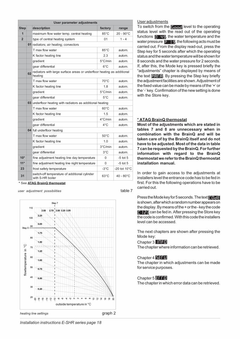
"�!����������������������������� ������������� ���������������������������������������� 8����������������!���������������������������!�����������0������4E1������ �����������������!���������������.� ��$������������������ �5�F�������� �������������������� �������������������"���$����������������������� ������� � ����������)��*�������������������@���2�$������#�� ����������!�������������������������������� � �������������������������������� "���� A� ��� ��� ��������� ��� ����!���� ���� ��� ���������������������������@�$�������� �����������)��=��>�������������� �������������������������� � �������������4�D������ �� ���� ��������� ������� �� ����� ��7�������������������������������
'��������������������������� ������������� ��������'����������������� �0������441������ ����������������'�����������������������������������.� ��$���A�F��������� ������������������� �������������������"����$��������������������� �� ����� ������� � �������������� ��������������������������������� ����������� ��������������������)����������������� �����������
���� ���������������������������������� ���� ��������� ��������������� � ���������������� ������"��� ������������������#���� ����������������.� ��$������������� ������ ��������)������ ��� ������������ �������������������� 2���*���� ������������������=��� >��� 2�������������������������9E����������������!����������������$������!�������� �
������������������ ���������� ������4E
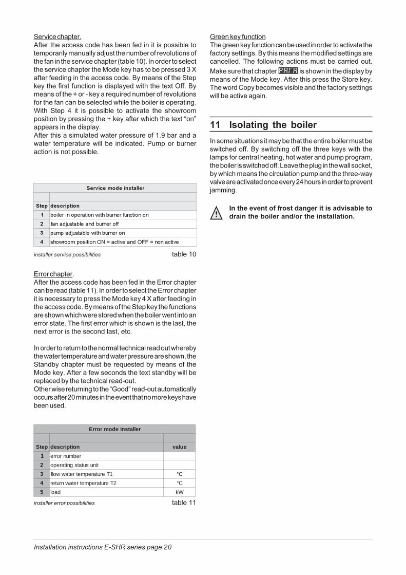
������������ ��� ���������� ������44
rellatsniedomrorrE
petS noitpircsed eulav
1 rebmunrorre
2 tinusutatsgnitarepo
3 1Terutarepmetretawwolf C°
4 2Terutarepmetretawnruter C°
5 daol Wk
������������������
���� ���������
� ��������� ������ �������������������
� �����������������$����
� �������� ���������$�����
� �"�������%&&'����"����%('������������ �
�����$�������������������$�������������������� ����� ���������!�������������������������������������������� ���� �������������������� ����������� ����������������������� ����
.�$����������������� ������� ��������� ����������������������.� ��$�����������������������"����$������� � ��������������!��������� �������������������� �����������!��������
�� ��������� �� � ��� �
�������������������������������������������������������� ����� ���������� ���������������������$���� ������������������������������������ ������ ������������������������� ����� ������,��!����������������� �������$������ ������������������������������� ���������2 ��!��!���������!��� �������!���9A��������� �������!���8�������
�������������������������������������,��������������,��������0�������������������
Installation instructions E-SHR series page 21
12 CommissioningWork on the boiler must be carried out by acompetent person, (Ref: Gas SafetyInstallation and Use ) using correctlycalibrated instruments with current testcertification.
The casing is fixed by 4 quick release clamps and 5screws (4x 1 clamp and 1 behind door). After removing thescrew, unlock the clamps, now the casing can beremoved.
With the E-SHR settings such as burner pressure andadjustment of the air quantity are unnecessary, due to thefact that the boiler operates with a so-called zero pressurecontrol. By this means the correct gas quantity iscontrolled by the suction operation of the fan. The fineadjustment which is carried out at the factory is once-only, which means that adjusting of these values isunnecessary.
Following maintenance or other activities;always check the installation of all parts throughwhich gas flows (using leak-search spray).
12.1 Checking for contamination
In order to be able to check the boiler forcontamination in the following running yearsit is advisable to measure the maximum airdisplacement in the boiler when putting theboiler into operation. This value can be diffe-rent with each type of boiler.
In order to be able to measure this value the followingoperations must be carried out:- in order to enter the service chapter feed in the access
code as described on page 18-20;- select the manual fan setting without burner action
Step , by means of the Step key which willindicate that the fan is off ;
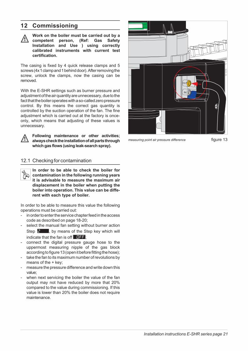
- connect the digital pressure gauge hose to theuppermost measuring nipple of the gas blockaccording to figure 13 (open it before fitting the hose);
- take the fan to its maximum number of revolutions bymeans of the + key;
- measure the pressure difference and write down thisvalue;
- when next servicing the boiler the value of the fanoutput may not have reduced by more that 20%compared to the value during commissioning. If thisvalue is lower than 20% the boiler does not requiremaintenance.
measuring point air pressure difference figure 13
Installation instructions E-SHR series page 22
13 MaintenanceMaintenance or changes to the unit may onlybe carried out by an authorised technician.
13.1 The frequency of maintenance
We advise to carry out an inspection to the boiler everytwo years and an overhaul every four years. When doingthis the circumstances of the boiler’s location must betaken into account, From this one can determine whetherto deviate from this advice.
13.2 Maintenance activities
If it is necessary to clean the boiler the following actionsto the following components must be carried out:
The air unit (casing of the boiler)Dirt which is sucked in by the air supply pipe will end upat the bottom of the casing. This dirt can be cleaned witha cloth with a simple (non-abrasive) cleaning agent.
The burner ceramic bricks and heat exchangerThese components should only be cleaned if it isdetermined that the maximum Pa is no longer obtained asdescribed in chapter 12.1.
The fan unit must be removed in order to beable to inspect the heat exchanger.
In this case the following actions must be carried out:- close the gas valve and isolate the boilers electrical
supply;- loosen the nut of the gas pipe under the gas block;- loosen the small crosshead screw on the red
electrical connection adaptor of the gas block;- remove the electrical connection plug from the fan
motor;- loosen the front crosshead screw of the black plastic
air inlet damper;- after this turn the two clamping rods ¼ turn and remove
them by pulling them forward;- slightly lift the fan unit and remove it towards the front
of the heat exchanger;- the fan unit and the air inlet damper can be checked
for contamination and if necessary cleaned;- now remove the burner ceramic bricks by slightly
lifting them upward and removing them in the samedirection as the heat exchanger fan unit;
- the burner ceramic bricks and the heat exchanger canbe cleaned by means of a soft brush;
Do not flush the heatexchanger through withwater
Refitting of the components is done in reverse.
12.2 Checking the CO2
The CO2 percentage is factory-set. This has tobe checked during check up, service anderror intervalls.
- remove the black cover from the gas valve by meansof unscrewing the by paint sealed screw.
- put the boiler into operation by means of the servicechapter as described in chapter 10.3;
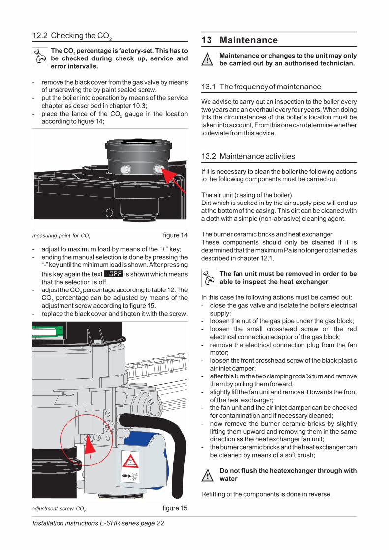
- place the lance of the CO2 gauge in the locationaccording to figure 14;
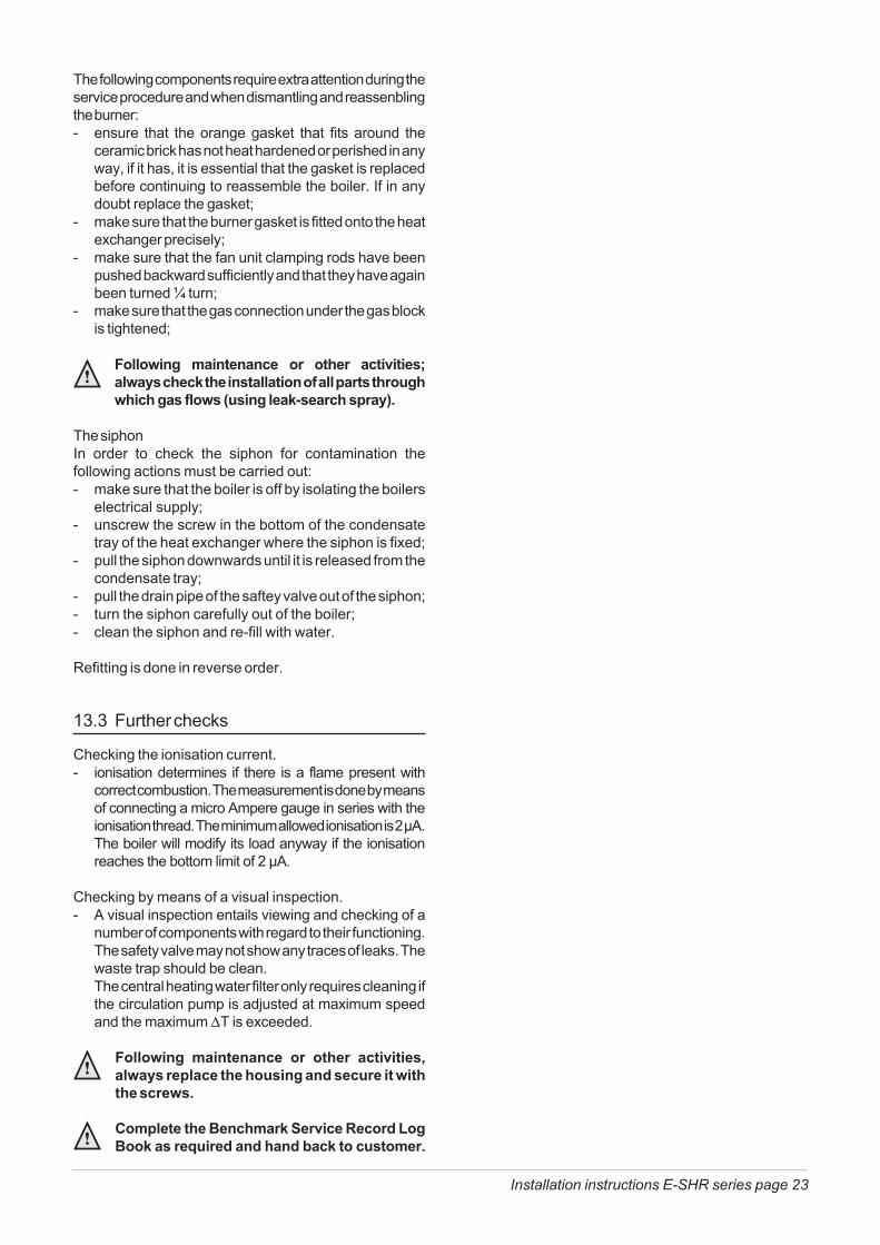
adjustment screw CO2 figure 15
measuring point for CO2 figure 14
- adjust to maximum load by means of the “+” key;- ending the manual selection is done by pressing the
“-” key until the minimum load is shown. After pressingthis key again the text is shown which meansthat the selection is off.
- adjust the CO2 percentage according to table 12. TheCO2 percentage can be adjusted by means of theadjustment screw according to figure 15.
- replace the black cover and tihgten it with the screw.
Installation instructions E-SHR series page 23
The following components require extra attention during theservice procedure and when dismantling and reassenblingthe burner:- ensure that the orange gasket that fits around the
ceramic brick has not heat hardened or perished in anyway, if it has, it is essential that the gasket is replacedbefore continuing to reassemble the boiler. If in anydoubt replace the gasket;
- make sure that the burner gasket is fitted onto the heatexchanger precisely;
- make sure that the fan unit clamping rods have beenpushed backward sufficiently and that they have againbeen turned ¼ turn;
- make sure that the gas connection under the gas blockis tightened;
Following maintenance or other activities;always check the installation of all parts throughwhich gas flows (using leak-search spray).
The siphonIn order to check the siphon for contamination thefollowing actions must be carried out:- make sure that the boiler is off by isolating the boilers
electrical supply;- unscrew the screw in the bottom of the condensate
tray of the heat exchanger where the siphon is fixed;- pull the siphon downwards until it is released from the
condensate tray;- pull the drain pipe of the saftey valve out of the siphon;- turn the siphon carefully out of the boiler;- clean the siphon and re-fill with water.
Refitting is done in reverse order.
13.3 Further checks
Checking the ionisation current.- ionisation determines if there is a flame present with
correct combustion. The measurement is done by meansof connecting a micro Ampere gauge in series with theionisation thread. The minimum allowed ionisation is 2 µA.The boiler will modify its load anyway if the ionisationreaches the bottom limit of 2 µA.
Checking by means of a visual inspection.- A visual inspection entails viewing and checking of a
number of components with regard to their functioning.The safety valve may not show any traces of leaks. Thewaste trap should be clean.The central heating water filter only requires cleaning ifthe circulation pump is adjusted at maximum speedand the maximum �T is exceeded.
Following maintenance or other activities,always replace the housing and secure it withthe screws.
Complete the Benchmark Service Record LogBook as required and hand back to customer.
Installation instructions E-SHR series page 24
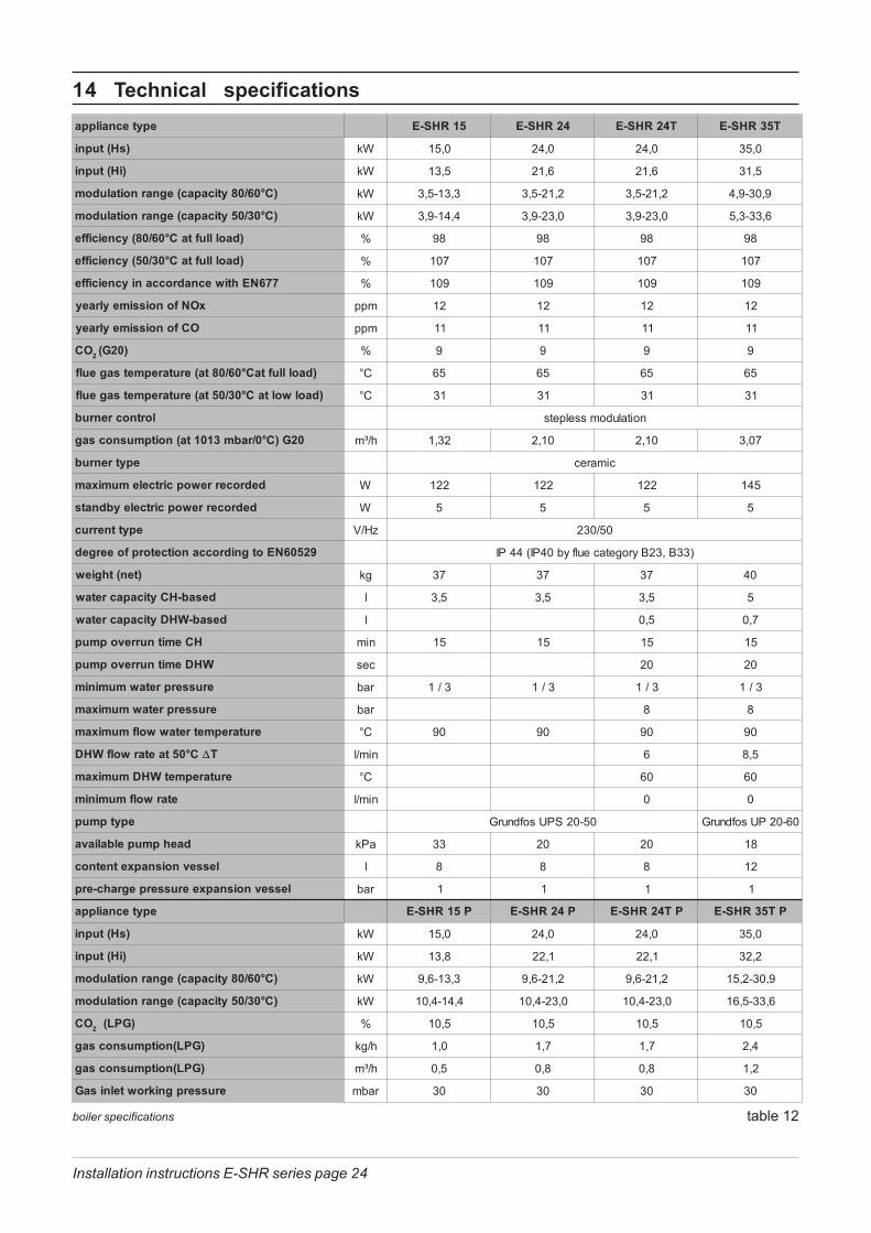
14 Technical specifications
boiler specifications table 12
epytecnailppa RHS-E 51 RHS-E 42 T42RHS-E T53RHS-E
)sH(tupni Wk 51 0, 0,42 0,42 0,53
)iH(tupni Wk ,31 5 6,12 6,12 5,13
)C°06/08yticapac(egnarnoitaludom Wk -5,3 3,31 2,12-5,3 2,12-5,3 9,03-9,4
)C°03/05yticapac(egnarnoitaludom Wk 4,41-9,3 0,32-9,3 0,32-9,3 6,33-3,5
)daollluftaC°06/08(ycneiciffe % 89 89 89 89
)daollluftaC°03/05(ycneiciffe % 701 701 701 701
776NEhtiwecnadroccaniycneiciffe % 901 901 901 901
xONfonoissimeylraey mpp 21 21 21 21
OCfonoissimeylraey mpp 11 11 11 11
OC 2 )02G( % 9 9 9 9
)daollluftaC°06/08ta(erutarepmetsageulf C° 56 56 56 56
)daolwoltaC°03/05ta(erutarepmetsageulf C° 13 13 13 13
lortnocrenrub noitaludomsselpets
02G)C°0/rabm3101ta(noitpmusnocsag h/³m 23,1 01,2 01,2 70,3
epytrenrub cimarec
dedrocerrewopcirtcelemumixam W 221 221 221 541
dedrocerrewopcirtceleybdnats W 5 5 5 5
epyttnerruc zH/V 05/032
92506NEotgnidroccanoitcetorpfoeerged 04PI(44PI yrogetaceulfyb )33B,32B
)ten(thgiew gk 73 73 73 04
desab-HCyticapacretaw l 5,3 5,3 5,3 5
desab-WHDyticapacretaw l 5,0 7,0
HCemitnurrevopmup nim 51 51 51 51
WHDemitnurrevopmup ces 02 02
muminim erusserpretaw rab 3/1 3/1 3/1 3/1
mumixam erusserpretaw rab 8 8
erutarepmetretawwolfmumixam C° 09 09 09 09
C°05taetarwolfWHD �T nim/l 6 5,8
erutarepmetWHDmumixam C° 06 06
etarwolfmuminim nim/l 0 0
epytpmup sofdnurG -02SPU 50 sofdnurG -02PU 60
daehpmupelbaliava aPk 33 02 02 81
lessevnoisnapxetnetnoc l 8 8 8 21
lessevnoisnapxeerusserpegrahc-erp rab 1 1 1 1
epytecnailppa P51RHS-E P42RHS-E PT42RHS-E RHS-E 53 PT
)sH(tupni Wk 0,51 0,42 0,42 0,53
)iH(tupni Wk 8,31 1,22 1,22 2,23
)C°06/08yticapac(egnarnoitaludom Wk 3,31-6,9 2,12-6,9 2,12-6,9 9,03-2,51
)C°03/05yticapac(egnarnoitaludom Wk 4,41-4,01 0,32-4,01 0,32-4,01 6,33-5,61
OC 2 )GPL( % 5,01 5,01 5,01 5,01
)GPL(noitpmusnocsag h/gk 0,1 7,1 7,1 4,2
)GPL(noitpmusnocsag h/³m 5,0 8,0 8,0 2,1
erusserpgnikrowtelnisaG rabm 03 03 03 03
Installation instructions E-SHR series page 25
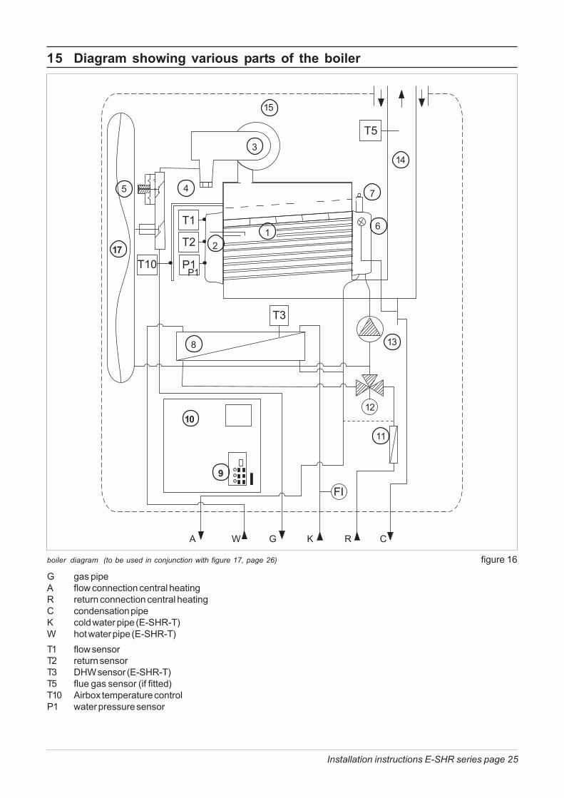
G gas pipeA flow connection central heatingR return connection central heatingC condensation pipeK cold water pipe (E-SHR-T)W hot water pipe (E-SHR-T)T1 flow sensorT2 return sensorT3 DHW sensor (E-SHR-T)T5 flue gas sensor (if fitted)T10 Airbox temperature controlP1 water pressure sensor
15 Diagram showing various parts of the boiler
boiler diagram (to be used in conjunction with figure 17, page 26) figure 16
A W G K R C
P1
8
3
15
7
14
21
45
6
11
13
1210
9
17
Installation instructions E-SHR series page 26
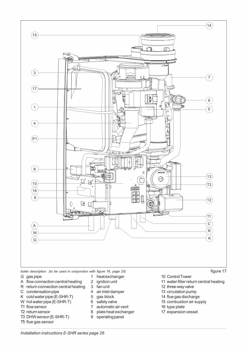
1 heat exchanger2 ignition unit3 fan unit4 air inlet damper5 gas block6 safety valve7 automatic air vent8 plate heat exchanger9 operating panel
boiler description (to be used in conjunction with figure 16, page 25) figure 1710 Control Tower11 water filter return central heating12 three-way valve13 circulation pump14 flue gas discharge15 combustion air supply16 type plate17 expansion vessel
G gas pipeA flow connection central heatingR return connection central heatingC condensation pipeK cold water pipe (E-SHR-T)W hot water pipe (E-SHR-T)T1 flow sensorT2 return sensorT3 DHW sensor (E-SHR-T)T5 flue gas sensor
13
14
12
10
9
7
6
5
4
3
P1
17
15
8
R
C
G
W
A
11
T316
1
K
Installation instructions E-SHR series page 27
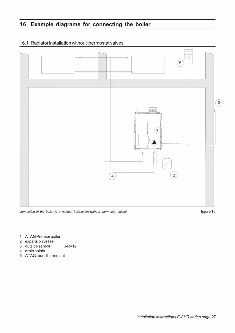
1 ATAG Premier boiler2 expansion vessel3 outside sensor ARV124 drain points5 ATAG room thermostat
16 Example diagrams for connecting the boiler
16.1 Radiator installation without thermostat valves
connecting of the boiler to a radiator installation without thermostat valves figure 18
1
2
3
4
5
Installation instructions E-SHR series page 28
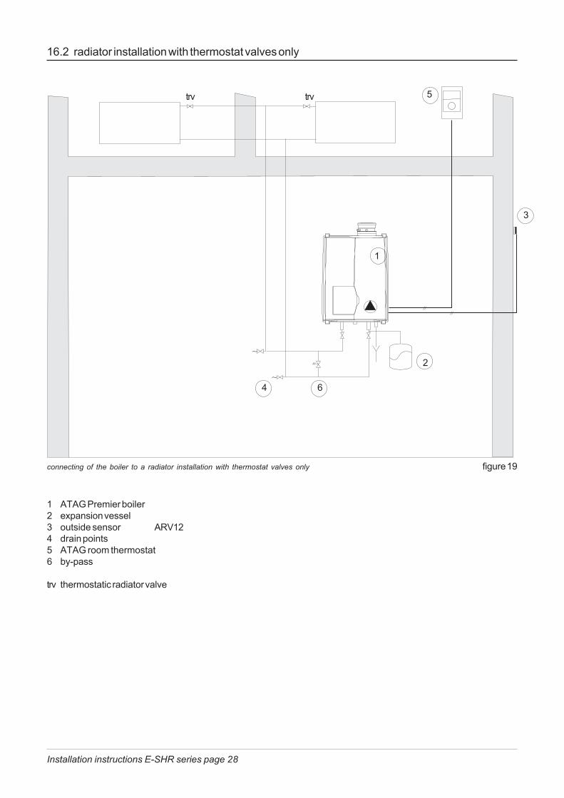
16.2 radiator installation with thermostat valves only
connecting of the boiler to a radiator installation with thermostat valves only figure 19
1
2
3
4
5
6
1 ATAG Premier boiler2 expansion vessel3 outside sensor ARV124 drain points5 ATAG room thermostat6 by-pass
trv thermostatic radiator valve
trv trv
Installation instructions E-SHR series page 29
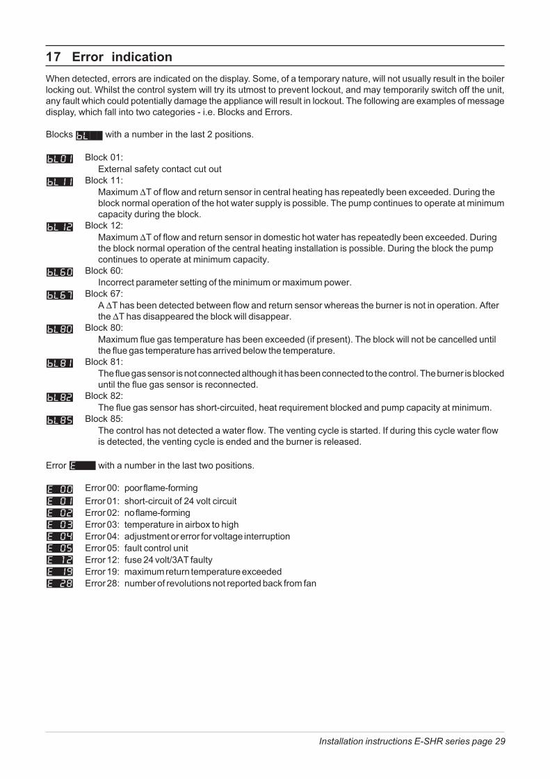
17 Error indicationWhen detected, errors are indicated on the display. Some, of a temporary nature, will not usually result in the boilerlocking out. Whilst the control system will try its utmost to prevent lockout, and may temporarily switch off the unit,any fault which could potentially damage the appliance will result in lockout. The following are examples of messagedisplay, which fall into two categories - i.e. Blocks and Errors.
Blocks with a number in the last 2 positions.
Block 01:External safety contact cut out
Block 11:Maximum �T of flow and return sensor in central heating has repeatedly been exceeded. During theblock normal operation of the hot water supply is possible. The pump continues to operate at minimumcapacity during the block.
Block 12:Maximum �T of flow and return sensor in domestic hot water has repeatedly been exceeded. Duringthe block normal operation of the central heating installation is possible. During the block the pumpcontinues to operate at minimum capacity.
Block 60:Incorrect parameter setting of the minimum or maximum power.
Block 67:A �T has been detected between flow and return sensor whereas the burner is not in operation. Afterthe �T has disappeared the block will disappear.
Block 80:Maximum flue gas temperature has been exceeded (if present). The block will not be cancelled untilthe flue gas temperature has arrived below the temperature.
Block 81:The flue gas sensor is not connected although it has been connected to the control. The burner is blockeduntil the flue gas sensor is reconnected.
Block 82:The flue gas sensor has short-circuited, heat requirement blocked and pump capacity at minimum.
Block 85:The control has not detected a water flow. The venting cycle is started. If during this cycle water flowis detected, the venting cycle is ended and the burner is released.
Error with a number in the last two positions.
Error 00: poor flame-formingError 01: short-circuit of 24 volt circuitError 02: no flame-formingError 03: temperature in airbox to highError 04: adjustment or error for voltage interruptionError 05: fault control unitError 12: fuse 24 volt/3AT faultyError 19: maximum return temperature exceededError 28: number of revolutions not reported back from fan

Installation instructions E-SHR series page 30
18 CE-Certificate United Kingdom

Installation instructions E-SHR series page 31
19 CE-Certificate Ireland

This renewed publication cancels all previous installation instructions.The company reserves the right to change the specifications and dimensions without prior notice
E. & O. E.