installation & service manual - harmar...• joint pins and joint brackets (two-piece rail only)...
TRANSCRIPT

31JAN2020 | P/N: 75403 Rev C
PINNACLE STAIR LIFTSL600 HD
INSTALLATION & SERVICE MANUAL


HEAVY DUTY STAIR LIFT TABLE OF CONTENTS
SL600HD Heavy Duty Stair Lift: Installation & Service Manual31JAN2020 | P/N: 75403 REV C
3
Table of ContentsINTRODUCTION .............................................. 4
Device Name: Pinnacle SL600HD Stair Lift ...............4Read and Understand .....................................................4Technical Specifications ................................................. 4
SAFETY ................................................................ 5Safety Definitions ............................................................5Required Practices ...........................................................5
PREPARATION .................................................. 6Required Tools .................................................................6Unpacking the Lift ...........................................................6Checking the Box Contents ...........................................7Included Parts ..................................................................7
PREPARATION .................................................. 8Determine Overall Rail Length .................................... 8
INSTALLATION .................................................. 9Rail Installation ............................................................... 9Chassis Installation ..................................................... 10Final Rail Installation .................................................. 11Footrest & Seat Installation ...................................... 12
Remote Control Programming ................................. 14Final Testing .................................................................. 15
SL600HD Heavy Duty Stair Lift: Installation & Service Manual31JAN2020 | P/N: 75403 REV C
4
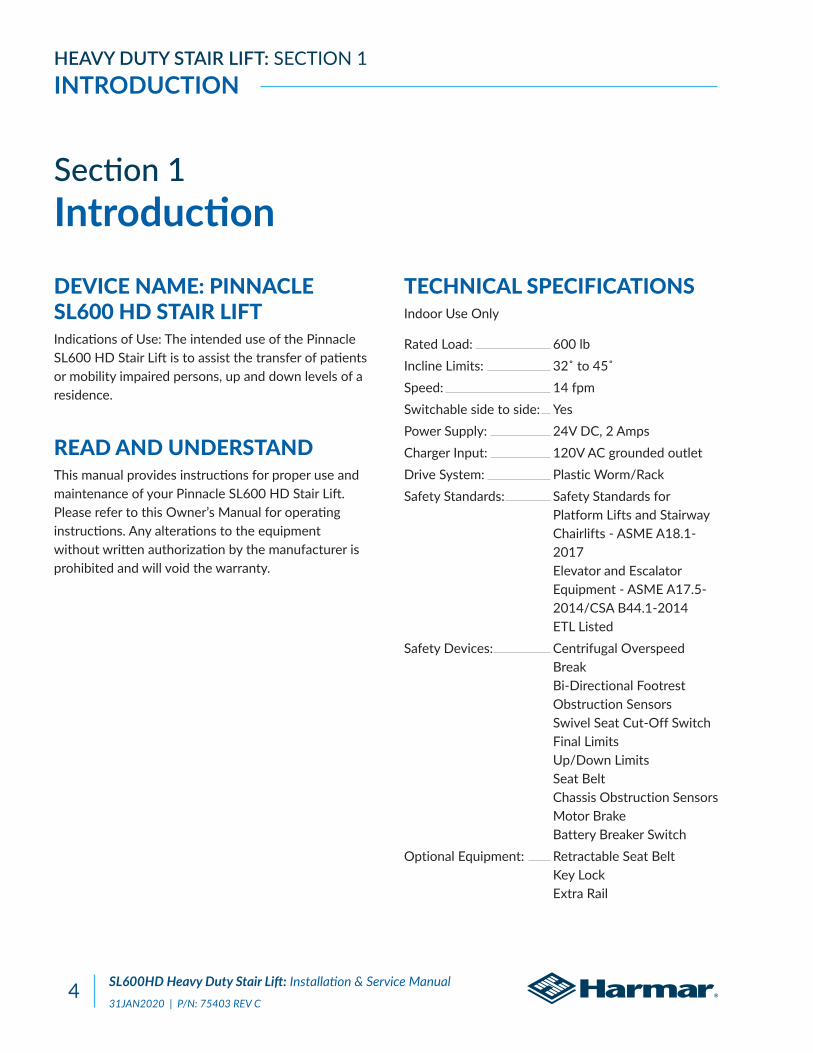
HEAVY DUTY STAIR LIFT: SECTION 1INTRODUCTION
Section 1IntroductionDEVICE NAME: PINNACLE SL600 HD STAIR LIFTIndications of Use: The intended use of the Pinnacle SL600 HD Stair Lift is to assist the transfer of patients or mobility impaired persons, up and down levels of a residence.
READ AND UNDERSTANDThis manual provides instructions for proper use and maintenance of your Pinnacle SL600 HD Stair Lift. Please refer to this Owner’s Manual for operating instructions. Any alterations to the equipment without written authorization by the manufacturer is prohibited and will void the warranty.
TECHNICAL SPECIFICATIONSIndoor Use Only
Rated Load: 600 lbIncline Limits: 32˚ to 45˚Speed: 14 fpmSwitchable side to side: YesPower Supply: 24V DC, 2 AmpsCharger Input: 120V AC grounded outletDrive System: Plastic Worm/RackSafety Standards: Safety Standards for Platform Lifts and Stairway Chairlifts - ASME A18.1- 2017 Elevator and Escalator Equipment - ASME A17.5- 2014/CSA B44.1-2014 ETL ListedSafety Devices: Centrifugal Overspeed Break Bi-Directional Footrest Obstruction Sensors Swivel Seat Cut-Off Switch Final Limits Up/Down Limits Seat Belt Chassis Obstruction Sensors Motor Brake Battery Breaker SwitchOptional Equipment: Retractable Seat Belt Key Lock Extra Rail

SL600HD Heavy Duty Stair Lift: Installation & Service Manual31JAN2020 | P/N: 75403 REV C
5
HEAVY DUTY STAIR LIFT: SECTION 2SAFETY
Section 2SafetySAFETY DEFINITIONS
This safety alert symbol appears with safety statements. It means attention, become alert, your safety is involved! Please read and abide by the message
that follows the safety alert symbol.
NOTE: Indicates a condition that should be followed in order for the lift to function in the manner intended.
REQUIRED PRACTICESNOTE: Installation of this lift requires one person, as long as the one person follows installation instructions, has completed training, has obtained certification on installation, is able to instruct the user on the correct operation and has established a safety and maintenance schedule.
Environmental ConditionsThe technician shall assess the surrounding conditions and verify that the location is acceptable before performing installation and/or servicing tasks.
NOTE: If you do not understand any portion of the installation or operation procedures, please consult our Technical Service Department or authorized dealer. Do not attempt to install or use this lift if you have any hesitation or question. Serious injury or damage can result if proper procedures are not followed.
!
Indicates a hazardous situation that, if not avoided, could result in death or serious injury.
WARNING!
Indicates a hazardous situation that, if not avoided, could result in minor or moderate injury.
CAUTION!
Indicates a situation which can cause damage to the lift and/or the environment, or cause the lift to operate improperly.
NOTICE

SL600HD Heavy Duty Stair Lift: Installation & Service Manual31JAN2020 | P/N: 75403 REV C
6
HEAVY DUTY STAIR LIFT: SECTION 3PREPARATION
Section 3PreparationInstallations may vary to some degree, but below are the basic tools to have on hand for a Pinnacle Stair Lift installation.
If you have any questions, concerns or comments, please contact our Technical Service Department at 800-378-6648 or [email protected].
REQUIRED TOOLS• Allen Wrench:
• 5/64"
• 5/32"
• 3/16"
• 5/16"
• Cordless Drill
• Nut Driver:
• 3/8"
• 5/16"
• 6"-10" Driver Extension
• Level
• Hack Saw or Chop Saw
• SAE Socket Set
• SAE Wrenches
• Tape Measure
UNPACKING THE LIFT
Never attempt to pick up the lift from the box, ground or on/off a vehicle alone.

SL600HD Heavy Duty Stair Lift: Installation & Service Manual31JAN2020 | P/N: 75403 REV C
7
HEAVY DUTY STAIR LIFT: SECTION 3PREPARATION
CHECKING THE BOX CONTENTSBefore installing the lift, review each part against the packaging checklist to ensure that all parts have been included. If any parts are missing or damaged, immediately contact the dealer who sold the lift. DO NOT attempt to install or use a lift that has missing or damaged parts.
INCLUDED PARTS• Chassis Box:
• Chassis
• Call/Send Parts
• 2 Call/Send Hand Controls
• Battery Charger
• Installation Manual
• Owner’s Manual
• Rail Bracket Box:
• Rail Brackets (2, 3, 4, or 6 per set)
• Wood Screws (#14 x 2" (4 per rail bracket)
• Chair Box:
• Chair
• Back Rest
• Seat Belt
• Footrest Box:
• Footrest complete with Swivel Slide Rails and Swivel Pin Bracket
• Rear Seat Support
• Rail Box:
• Bottom Rail Pre-installation with Bottom End Plate and Charge Strip Wire Harness
• Bottom Limit Cam
• Joint Pins and Joint Brackets (two-piece rail only)
• Plastic Gear Rack
• Top Rail Pre-installed with Charge Strip Wire Harness
• Rail Accessories (Plastic Bag) with Top End Plate and Compression Bolts (2 sizes)
• Self-cutting screws ( 1/4" - 20 x 1")
• Torx T30 Driver Bit
• Rail Parts (Plastic Bag) with Extra Plastic Racks (2 or 3) and Top Limit Cam

SL600HD Heavy Duty Stair Lift: Installation & Service Manual31JAN2020 | P/N: 75403 REV C
8
HEAVY DUTY STAIR LIFT: SECTION 3PREPARATION
DETERMINE OVERALL RAIL LENGTH (ONLY IF TRACK DID NOT COME PRE-CUT TO LENGTH)
1. Determine obstructions that will affect the position and length of the rail, such as walls, doors, hallway orientation, etc.
2. Measure the overall length of the stairs from the nose at the top landing to the floor (nose to floor measurement). See Figure 3-1.
Figure 3-1
3. For a normal stairway with adequate landing space, add 7" to the nose to floor measurement. This will provide enough rail length to allow the stair lift to be adjusted so that the floor-to-seat height will be the same at both the top and the bottom.
4. If the top landing has restrictions (i.e. a wall or a doorway), use the chart to determine the length of extensions needed. See Figure 3-2.
Figure 3-2
5. To cut the rail, use a standard 12" chop saw, with a blade designed to cut aluminum.
Extension 7" 9" 11" 13"
Horizontal intrusion on top landing 3.9" 5" 6.1" 7.2"
Do not cut the rail inside the house (aluminum chips are very hard to remove from carpets).
NOTICE
Do not cut the end of the rail that contains the joint holes. Remove the charger strips and wire harness before cutting.
WARNING!

SL600HD Heavy Duty Stair Lift: Installation & Service Manual31JAN2020 | P/N: 75403 REV C
9
HEAVY DUTY STAIR LIFT: SECTION 4INSTALLATION
Section 4Installation RAIL INSTALLATION
1. Open the rail box and remove its contents.
2. Position the bottom rail (with end plate attached) directly on the stairs with the end plate towards the bottom of the stairs and the plastic rack facing up. Place an object the measures between 3/4" and 1" between end plate and floor.
NOTE: Use the chair box or another heavy object, like a toolbox, at the bottom to prevent the rail from sliding down the stairs.
3. Position the two ends of the track close together. Locate and connect the plug on the ends of the two charger harness inside the two track pieces.
4. With the plastic rack facing up, sliding the top rail into the bottom rail and guide them together using the pre-installed pins. Gently tap the top rail if necessary to get them close together. Be cautious not to pinch the charger harness.
5. Install two joint fasteners and firmly tighten with 3/16" Allen wrench. Then slide rack pieces down to cover joint. See Figure 4-1.
Figure 4-1
6. Turn over joined rails and install the remaining two join fasteners and firmly tighten with 3/16" Allen wrench. Then slide track pieces down to cover the joint.
7. Install the rail brackets by loosing the screws and snapping each bracket edge into the slot, or slide the brackets on from the top of the rail. See Figure 4-2.
Figure 4-2
8. For double rails, tighten the first rail brackets in place so, when it’s turned over, the back of the bracket touches the rear of the bottom step. Place and tighten the second and third brackets on the steps on each side of the rail joint, again so the back of the bracket touches the rear of the step. Place the fourth and final bracket on the top step before the landing, again tightening it so it touches the front of the last step. See Figure 4-3.
Figure 4-3
Tighten the first rail bracket in place so when turned over the back of the bracket touches the rear of the first step from the bottom landing.

SL600HD Heavy Duty Stair Lift: Installation & Service Manual31JAN2020 | P/N: 75403 REV C
10
HEAVY DUTY STAIR LIFT: SECTION 4INSTALLATION
Place the other rail on the last step before the top landing, again tightening it so it touches the rear of the last step. See Figure 4-4.
Figure 4-4
9. Turn the rail right side up with the plastic side facing up. See Figure 4-5.
Figure 4-5
10. Measure any obstruction from the wall (this may include handrails, molding, light switches, etc.) and adjust the edge of the brackets and equal distance from the wall. The edge of the track needs to be 7" from the wall or any obstruction. See Figure 4-6.
Figure 4-6
11. The underside of the rail must be at least 2" above the stair tread nose to provide clearance for the footrest. To achieve this 2" clearance move the rail and bracket forward. Once the clearance is 2" tighten all bracket nuts to hold the brackets in position. To maintain the 2"
clearance, and hold the rail in place, secure the bottom bracket to the first step from the floor with two 2" wood screws, using a 3/8" nut driver on a 6"-10" extension of a cordless drill.
CHASSIS INSTALLATION
1. Remove the plastic bag from the chassis box. Lift the chassis with the manual override hole (on bottom) facing the downhill side of the stairs and gently slide the chassis onto the rail until it makes contact with the plastic rack. DO NOT LET THE CHASSIS FALL DOWN THE RAIL. See Figure 4-7.
Figure 4-7
2. Remove the safety tie and turn the red “On/OFF” switch to the “ON” position. See Figure 4-8.
Figure 4-8
Remove two pieces of gear rack from the top end of the track before installing the chassis.
NOTICE
Be careful not to trap fingers between the rail and the chassis.
CAUTION!

SL600HD Heavy Duty Stair Lift: Installation & Service Manual31JAN2020 | P/N: 75403 REV C
11
HEAVY DUTY STAIR LIFT: SECTION 4INSTALLATION
3. Use the installation switch (the black switch on the top of the chassis) to move the chassis at least two feet down the rail, pushing gently on the chassis to ensure the chassis does not pull any rack to the top. See Figure 4-9.
Figure 4-9
FINAL RAIL INSTALLATION1. Install the remaining plastic rack pieces in the
upper rail. See Figure 4-10.
Figure 4-10
2. Use a hacksaw or chop saw to cut the last plastic rack piece flush with the rail end. Place something on the floor to catch debris or mark and cut the rack outside. The exposed, cut end of the plastic rack should face the top end of the rail (the factory-cut side should butt against the lower rack). See Figure 4-11.
Figure 4-11
3. Slide the top limit cam into one of the cam slots (either side), and tighten the pre-inserted Allen screw with a 5/64 Allen wrench. This will be used to set the final upper limits for the stair lift. See Figure 4-12.
Figure 4-12
4. Remove the charging strip from the rail box. Connect charging strip connector to the charger wire that runs through the center of the rail from the lower charging strips.
Insert the two charger strips into the keyed slots at the top of the rail (while standing on the top landing looking down). The charging strip with the red wire should be inserted into the left slot with the metal strip facing out. The charging strip with the black wire should be inserted into the right slot with the metal strip pointing out.
Bend the red and black wire tabs in toward the center of the rack.
Insert excess cable into the rail, leaving the pigtail with the Molex connector.
5. Install the end plate to the top of the rack with the four self-cutting Torx screws using the supplied T30 Torx bit. See Figure 4-13.
Do not ride on the chassis or lift until the install is complete.
CAUTION!

SL600HD Heavy Duty Stair Lift: Installation & Service Manual31JAN2020 | P/N: 75403 REV C
12
HEAVY DUTY STAIR LIFT: SECTION 4INSTALLATION
Figure 4-13
6. Install one of the rack pre-compression screws in the threaded hole in the top rail plate; tighten as firmly as possibly by hand with a 5/32" Allen wrench. See Figure 4-14.
There are three kinds of pre-compression screws: • 1" for tracks under 6' • 1 1/4" for tracks between 6' and over
Figure 4-14
7. Plug in the battery charger at either end of the rail, choosing the closest or most convenient location of a wall power supply. Minimize wire length and intrusion.
FOOTREST & SEAT INSTALLATION1. Remove footrest from box and use the
installation switch to drive the chassis downward to a position about 6" clear of the floor. This provides a safe area to install and adjust the footrest. Do not drive the unit into the bottom stop. See Figure 4-15.
Figure 4-15
2. Turn the red “On/Off” switch located on the top of the chassis to the “OFF” position.
3. Position the footrest onto the two seat-leveling bolts on the outside of the chassis by aligning the large opening at the slot ends of the footrest See Figure 4-16.
Figure 4-16
4. Ensure the footrest if fully engaged.
5. Position the rear seat support onto the two seat-leveling bolts on the backside of the chassis by aligning the large opening at the slot ends of the footrest. See Figure 4-17.
Too much torque applied to these screws may result in damage. Take your time and apply grease to threads.
CAUTION!

SL600HD Heavy Duty Stair Lift: Installation & Service Manual31JAN2020 | P/N: 75403 REV C
13
HEAVY DUTY STAIR LIFT: SECTION 4INSTALLATION
Figure 4-17
Secure the rear seat support to the footrest/seat support using the two hex-head bolts and washers. See Figure 4-18.
Figure 4-18
Secure the rear of the slider rails to the rear support using the two socket bolts. See Figure 4-19.
Figure 4-19
Ensure that the seat support is level and tighten the two front and two rear leveling bolts. See Figure 4-20.
Figure 4-20
6. Connect the footrest cable to the 6-pin connector on the chassis. See Figure 4-21.
Figure 4-21
NOTE: When the 6-pin footrest and the 8-pin chair cables are both connected to the chassis, the black installation switch on the chassis is disabled and will not function.
7. Align the seat rollers with the slider rails and slide the seat half way back. See Figure 4-22.
Figure 4-22
8. Swivel seat approximately 45˚ to one side. See Figure 4-23.
Figure 4-23
9. Attach the swivel pin bracket with the flat side towards the footrest support using the two hex head bolts and washers. Ensure that one of the swivel pins is engaged into the slot in the swivel cam. See Figure 4-24.

SL600HD Heavy Duty Stair Lift: Installation & Service Manual31JAN2020 | P/N: 75403 REV C
14
HEAVY DUTY STAIR LIFT: SECTION 4INSTALLATION
Figure 4-24
10. Connect the seat cable to the 8-pin connector on the chassis. See Figure 4-25.
Figure 4-25
11. If the lift is equipped with the optional key lock, ensure that the key switch on the armrest control is in the locked position; the key should be in the vertical position. See Figure 4-26.
Figure 4-26
12. Turn the red “ON/OFF” switch located on the top of the chassis to the “ON” position. You should hear a single beep and the LED indicator light on the armrest control should cycle through a test sequence, showing red, yellow and green respectively. If any of the system controls or safety sensors are engaged the LED indicator light will turn to yellow.
13. If the LED indicator light is not green, check the safety sensors. If the LED indicator light is still
not green after testing sensors, turn the unit off and re-check all wire plugs. Turn the unit on again and re-check the LED indicator light cycle. When the LED indicator light remains green, the lift is ready to operate. See Figure 4-27.
Figure 4-27
REMOTE CONTROL PROGRAMMING
All call/send controls are factory programmed. Re-programming is not normally necessary during installation. In the event that the remove call/send control needs to be re-programmed, it is essential to program BOTH controls in one programming cycle. Do so by completing the following.
1. Start with the red “ON/OFF” switch in the “Off” position.
2. Disconnect the 6-pin footrest and 8-pin chair wire harness from the chassis.
3. Press and hold the install switch (located on the
Seat swivel sensorSeat should be in the locked position
Footrest lower sensorCheck by pushing in on the safety pan on the footrest
Upper foot pan safety sensor
Check by pushing on the safety pan on the footrest
Front foot pan safety sensor
Check by pushing on the safety pan on the footrest
Uphill safety sensorEnsure nothing is blocking upward passage
Downhill safety sensorEnsure nothing is blocking downward passage

SL600HD Heavy Duty Stair Lift: Installation & Service Manual31JAN2020 | P/N: 75403 REV C
15
HEAVY DUTY STAIR LIFT: SECTION 4INSTALLATION
top of the chassis) in either direction.
4. Turn the red “ON/OFF” switch to the “ON” position, and then release the install switch.
5. The lift will begin to beep rapidly (this means the first remove control is ready to program).
6. Press and release the “UP” or “DOWN” button of the first remote control (the first remote control is now programmed).
7. Press and release the “UP” or “DOWN” button of the second remote control (the second remote control is now programmed).
8. Upon completion, two beeps will indicate that both remote controls have been programmed.
9. Turn the “ON/OFF” switch to the “OFF” position.
10. Connect the 6-pin footrest and 8-pin chair wire harness to the chassis and then turn the red “ON/OFF” switch to the “ON” position.
11. Test each remote control in both the up and down directions.
FINAL TESTING
Test Armrest Control Switch1. Ensure that the unit travels correctly by
operating the armrest control switch while standing in front of the unit.
2. Depress the switch in the upstairs direction to move up. The lift will beep, wait three seconds and begin to smoothly accelerate upwards. The lift will continue to move upwards as long as the switch is depressed.
3. Release the switch and the lift will come to an immediate stop.
4. Depress the switch in the downstairs direction to move down. The lift will beep, wait three seconds and begin to move downwards.
5. Release the switch and the lift will come to an immediate stop.
6. Run the chair all the way up and down the rail to ensure that the top of the seat back has at least a 1/2" clearance from the wall and any obstructions.
Tighten Brackets1. Install and fully tighten the rail bracket mounting
screws (four screws per bracket). For hardwood stairs, drill a pilot hole first. For plywood or particle board stairs, take care to prevent stripping.
Set Upper and Lower Travel Limits1. Test the lower travel limit by operating the lift
downward, keeping the switch depressed. The unit should begin to decelerate about 3" from its final resting position and stop clear of the floor.
2. The final stopped position can be adjusted to accommodate the height of the user by repositioning the limit cam located in a slot in the rail.
3. Use a 5/64" Allen wrench to loosen the set screw in the limit cam. Adjust the limit cam up or down and retighten the set screws. Repeat the above steps until the lift stops in the desired position.
4. Repeat the above steps to set the upper limits. For safety, the footrest should be set at least level with the upper landing.
5. The optimum position is met when the seat height above the floor is the same at the top and bottom of the stairs.
Test Safety Stop Switches1. Safety stop switches are located in both the
upward and downward ends of the chassis

SL600HD Heavy Duty Stair Lift: Installation & Service Manual31JAN2020 | P/N: 75403 REV C
16
HEAVY DUTY STAIR LIFT: SECTION 4INSTALLATION
providing protection from obstructions on the rail.
2. Safety stop switches are located in the footrest bottom pan providing protection from obstructions and trapping hazards on the stairs.
3. A safety stop switch is part of the swivel seat mechanism and prevents the lift from operating when the swivel is in use.
4. Test all the safety stop switches by driving the lift down and touching the downward end of the chassis, the lower edge of the footrest, and the underside of the footrest in both its folded and unfolded positions.
5. In each of the above cases the unit should come to an immediate halt. The LED indicator light on the armrest control should turn to orange and the unit should beep intermittently.
6. When the control switch is released, the unit should NOT be able to be driven in the direction that the lift initially engaged the obstacle. Test this condition.
7. Test to ensure that the lift can only be driven away from the obstruction. The LED indicator light will turn to green and stop beeping indicating a safe operating condition.
8. Repeat the above tests while driving the lift in opposite direction.
9. If any safety condition does not function properly, carefully review all installation instructions, reset the “ON/OFF” switch and check that the LED indicator light is green. Repeat the above tests.
10. If any safety stop switch fails to immediately stop the lift and/or a red LED indicator light appears, remove the key to prevent further use of the lift and immediately call the manufacturer for assistance in diagnosing and repairing the problem. DO NOT USE THE LIFT.
Additional System Checks1. After the successful testing of all safety
switches, secure the seat belt, sit on the lift and operate to the top of the stairs. Keeping the control switch depressed continuously, the lift should gently decelerate and then stop at the top of the track.
2. As a final adjustment, sit on the lift and do two complete up trips and stop with the chair at the bottom. Then tighten the compression screw in the top end plate, then run the chair to the top and again tighten the compression screw. Run the chair to the middle and do a final tightening of the compression screw.
3. Drive the lift to the bottom, keeping the control switch depressed all the time, and check that the lift gently decelerate and stops so the footrest pan is clear off the floor. If necessary adjust the limit cams with a 5/64" Allen wrench.
4. Move the lift about three (3) feet from either the top or bottom of the rail. After 30 seconds the armrest LED indicator light will show orange and beep indicating that the lift is not positioned on a charge point. The beep will stop after 30 seconds, but the armrest LED indicator light will continue to flash orange.
5. Test the seat swivel at the top by using the levers and swiveling the seat towards the landing and stop the seat at 35 and 85 degrees. The seat swivel levers will release into a locked position at each of these angles. The lift will not operate in any of these positions if the control switch is depressed, and the LED indicator light will turn orange. Return the seat to its normal position and the LED indicator light will turn green and the lift will now operate normally.
6. Drive to the top or bottom and check the battery charging light. If the light is orange or red, the batteries are being charged.

SL600HD Heavy Duty Stair Lift: Installation & Service Manual31JAN2020 | P/N: 75403 REV C
17
NOTES

SL600HD Heavy Duty Stair Lift: Installation & Service Manual31JAN2020 | P/N: 75403 REV C
18
NOTES

SL600HD Heavy Duty Stair Lift: Installation & Service Manual31JAN2020 | P/N: 75403 REV C
19
NOTES

2075 47th Street | Sarasota, FL 34234800.833.0478
harmar.com