installation & service instructions osprey cf 125 –...
TRANSCRIPT

Installation & Service Instructions Osprey CF125 – 220
About the Boiler See inside cover for models covered by these instructions.This Floor Standing Cast Iron Gas Boiler is available as Conventional Flue.This boiler is for use with Natural Gas (G20) at 20mbar or Propane Gas (G31) at 37mbar andfor use in GB & IE.
About Safety The Gas Safety (Installation and Use) Regulations 1994 (As Amended) & The GasSafety(Installation and Use) (Amendment) Regulations 1996.
‘‘ In your own interest, and that of safety, it is law that all gas appliances are installed bycompetent persons, in accordance with the above regulations. Failure to install appliancescorrectly could lead to prosecution.’’
Installation must be in accordance with the Installation & Service Instructions and the rules inforce.
Leave these instructions with the user for use on future calls.

Contents - Page 2
Technical Data ................................................................. 3The models covered by these instructions are:-
Introduction...................................................................... 5 Osprey 125 - G.C. No. 41 589 33Health & Safety Information ...................................... 5 Osprey 150 - G.C. No. 41 589 44Codes of Practice...................................................... 5 Osprey 180 - G.C. No. 41 589 45
Osprey 220 - G.C. No. 41 589 621. Installation Requirements ...................................... 6
1.1 Gas Supply ....................................................... 61.2 Electricity Supply .............................................. 61.3 Location of Boiler.............................................. 61.4 Air Supply ......................................................... 7 The boiler model and serial number are given1.5 Flue System...................................................... 8 on the boiler data label which is located on the1.6 The System ...................................................... 9 front outer casing fixing bracket.
2. Installation ............................................................. 132.1 Prepare the Boiler........................................... 132.2 Connect the Gas Supply................................. 142.3 Connect the Water Supply.............................. 142.4 Connect the Power Supply Cable................... 152.5 Install the Room Thermostat........................... 162.6 Install the Flue ................................................ 16
3. Commissioning ..................................................... 173.1 Commission the Boiler.................................... 183.2 Final Adjustments ........................................... 193.3 Instruct the User ............................................. 193.4 Advise the User .............................................. 19
4. Service & Replacement of Parts .......................... 204.1 General Access .............................................. 214.2 Control Panel.................................................. 214.3 TTB Thermostat.............................................. 224.4 Boiler Thermostat ........................................... 224.5 Overheat Thermostat...................................... 224.6 Burner Assembly ............................................ 224.7 Gas Valve ....................................................... 234.8 Pilot Interrupter ............................................... 234.9 Pilot Assembly ................................................ 234.10 Burner............................................................. 234.11 Cleaning Heat Exchanger............................... 23
5. Wiring Diagrams...................................................... 24
6. Fault Finding ........................................................... 26
7. Short List of Spares................................................. 29Fig. 1
SAFETY, PERFORMANCE & QUALITY
Osprey boilers have been assessed by a Governmentappointed Notified Body and shown to meet the 'EssentialRequirements' of the European Gas Appliance Directive.The Directive lays down requirements for the safety and
efficiency of the appliance, together with its design,construction, and use of materials.
It also requires the production process to be covered by anapproved and monitored system of quality assurance.

Technical Data - Page 3
Heat Input & Efficiency figures arequoted as gross
Boiler models
Maximum Rate 125 150 180 220
Output kW 35.0 43.0 52.8 64.5Btu/h 119,420 146,716 180,154 220,074
Input kW 43.09 53.12 64.79 79.77Btu/h 147,020 181,245 221,063 272,171
Gas rate (G20) m3/h 4.10 5.06 6.17 7.60ft3/h 145 179 218 268
Injector Size mm 2.6 2.6 2.6 2.6Burner Pressure mbar 12.8 12.2 13.3 13.8
Permanent Pilot mm 2 Holes Ø 0.29InjectorCombustion g/s 30.56 33.89 39.44 47.50Product RatePrimary Flue Temp. °C 170 165 150 155
LPG Gas Rate(G31) kg/h 3.01 3.7 4.6 5.6Injector Size mm 1.75 1.75 1.75 1.75Burner Pressure mbar 36.5 36.5 36.5 36.5
Permanent Pilot mm 1 Hole Ø 0.24Injector
Efficiency (Gross) % 81.2 80.9 81.5 80.9Injector Size mm 1.75 1.75 1.75 1.75
Water Content Litres 24 29 33 38Appliance Weight kg 135 165 195 225Nominal flow l/min 45.6 56.0 68.8 84.0for temp. diff. of 11KPressure Loss mbar 9.7 18.7 27.5 55.9for temp. diff. of 11K
Maximum Working Head 30m (3 bar)Minimum Working Head 0.5mGas Supply Pressure G20 - 20mbar G31 - 37mbarGas Supply Connection 22mm Copper pipe with female compression fittingMaximum Flow Temperature 85°CFlow Connection 11/4/" Steel pipe, taper threadReturn Connection 11/4" Steel pipe, taper threadElectricity Supply 230v ~ 50Hz Fused at 3APower Consumption 10 Watts (excluding pump)Classifications CAT 11 2H 3P - B11Bs - IP20

TECHNICAL DATA - Page 4
Fig. 2
Introduction - Page 5
The Gas Safety (Installation and Use) Regulations 1994 (AsAmended) & The Gas Safety (Installation and Use)(Amendment) Regulations 1996.
This appliance must be installed and serviced by acompetent person, in accordance with the above regulations.
In the UK 'Corgi' Registered Installers (including the regionsof British Gas Plc) undertake to work to a safe andsatisfactory standard.
Failure to install appliances correctly could lead toprosecution.
It is in your own interest, and that of safety, to ensure thatthe regulations are complied with.
Osprey boilers are fully automatically controlled, floorstanding, conventional flued appliances using a cast ironheat exchanger and are available in outputs ranging from35.0 - 64.5 kW.
The boilers are designed for use on fully pumped openvented or sealed water systems with an indirect hot watercylinder.
THEY MUST NOT BE CONNECTED TO A DIRECTCYLINDER.
The boilers are for use on Natural Gas (G20) and LPG(G31).
Samples of the Potterton Osprey gas boilers have beenexamined by Ctif, a France Notified Body. The range iscertified to comply with the essential requirements of theGas Appliance Directive 90/396/EEC, the Low VoltageDirective 72/23/EEC and shows compliance with the ElectroMagnetic Compatibility Directive 89/336/EEC and aretherefore permitted to carry the CE Mark.
Delivery & Kits Available
The unit is delivered in one package, the boiler with fittingsand the flue spigot.
Health and Safety Information for the Installer andService Engineer
Under the Consumer Protection Act 1987 and Section 6 ofthe Health and Safety at Work Act 1974, we are required toprovide information on substances hazardous to health.
Small quantities of adhesives and sealants used in theproduct are cured and present no known hazards.
The following substances are also present.
Insulation and Seals
Material - Ceramic Fibre. Alumino - Silicone Fibre.
Description - Boards, Ropes, Gaskets.
Known Hazards - Some people can suffer reddeningand itching of the skin. Fibre entry into the eye willcause foreign body irritation. Irritation to respiratorytract.
Precautions - People with a history of skin complaintsmay be particularly susceptible to irritation. High dustlevels are only likely to arise following harsh abrasion.In general, normal handling and use will not causediscomfort, follow good hygiene practices. Wash handsbefore consuming food, drinking or using the toilet.
First Aid - Medical attention must be sought followingeye contact or prolonged reddening of the skin.
Codes of Practice
The boiler must be installed in accordance with: The GasSafety (Installation and Use) Regulations 1994 (AsAmended) & The Gas Safety (Installation and Use)(Amendment) Regulations 1996. and the current issue of:-
The Building Regulations, Building Standards (Scotland)Regulations, Local Building Regulations, Model and localWater Undertaking Bye-laws, IEE Wiring Regulations andHealth & Safety Document No. 635 "The Electricity at WorkRegulations 1989".
IMPORTANT
This appliance has been certified for safety. It is therefore important that no external control device (e.g. flue dampers,economisers, etc.) be directly connected to the appliance unless covered by these Installation & Service Instructionsor otherwise recommended in writing.
Any direct connection of a control device not approved by Potterton Myson Ltd, could invalidate theCE Certification and normal appliance warranty.
1. Installation Requirements - Page 6
1.1 Gas Supply
The meter and supply pipes must be capable of deliveringthe required quantity of gas in addition to the demand fromany other appliances in the house and must be governed atthe meter.
If this is not achieved the local gas supplier must becontacted.
A minimum 22mm gas supply pipe should be used up to theinlet connection of the gas cock on the boiler. The pipediameter required will depend upon the length - see Section2. and BS 5449: 1990 - Appendix B.
The complete installation must be tested for gas soundnessand purged as described in BS6891.
1.2 Electricity Supply
230V ~ 50Hz via a fused double pole switch with a contactseparation of at least 3 mm in both poles adjacent to theboiler. Power consumption is approximately 10W. Theremust be only one common isolator for the boiler and itscontrol system and it must provide complete electricalisolation. A plug complying with the requirements of BS 1363(if fitted) must be accessible to the user after installation ofthe appliance.
Fuse the supply at 3 A. The minimum requirement for thepower supply cable is that it should be a PVC sheathed cordat least 0.75 mm2 (24 x 0.2 mm) (code designation HO5 VV-F or HO5 VVH2-F) as specified in table 16 of BS6500:1984.
All wiring external to the boiler shall comply with the latestIEE Wiring Regulations, and any local regulations whichapply.
WARNING: THIS APPLIANCE MUST BE EARTHED.
In the event of an electrical fault after installation of theboiler, preliminary electrical systems checks must be carriedout i.e. Earth Continuity, Short Circuit, Polarity andResistance to Earth.
1.3 Location of Boiler
The boiler is not suitable for external installation. The boilermust stand firm and level on a non combustible surface. Nospecial floor protection is needed, but finishes which softenwhen warm e.g. linoleum and plastic floor tiles should beremoved or may be protected by an insulating sheet at least10mm thick.
The boiler must be installed so that the draft diverter is infree air according to the clearance dimensions shown inFig. 2.
The flue duct should not be closer than 25 mm tocombustible material. A metal sleeve should be installed tosurround the flue duct to provide a 25mm annular space.Further guidance is given in BS5440:1:1990, sub-clauses3.3 and 4.2.5.
If the boiler is to be installed in a timber framed building itshould be fitted in accordance with the British Gaspublication- Part 19 - Building and Kitchen Work. If in doubtadvice must be sought from Potterton Myson.
Conventional flue boilers can be installed either in a kitchenor utility room or (125 and 150 models only) inside a suitablyventilated, purpose designed or modified compartment.
Where the installation of the boiler will be in an unusualposition, special procedures may be necessary and BS6798and BS5546 give detailed guidance on this aspect.
A compartment used to enclose the boiler is only allowed ifthe clearances shown in Fig. 2 and the air requirements ofBS 5440 Part 2 are followed to allow correct functioning ofthe draft diverter (125 and 150 models only).
If the boiler is to be fitted in a run of kitchen units it isrecommended that the boiler is fitted first or the adjacentunits removed.
The boiler requires the clearances shown in Fig. 2.
Installation Requirements - Page 7
Conventional Flue Models
1.4 Air Supply
The air requirements must meet BS 5440 Part 2 & BS 6644.
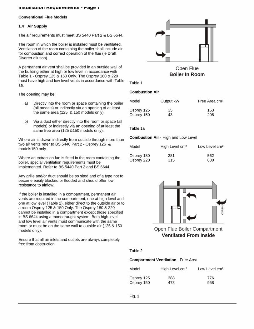
The room in which the boiler is installed must be ventilated.Ventilation of the room containing the boiler shall include airfor combustion and correct operation of the flue (ie DraftDiverter dilution).
A permanent air vent shall be provided in an outside wall ofthe building either at high or low level in accordance withTable 1 - Osprey 125 & 150 Only. The Osprey 180 & 220must have high and low level vents in accordance with Table1a.
The opening may be:
a) Directly into the room or space containing the boiler(all models) or indirectly via an opening of at leastthe same area (125 & 150 models only).
b) Via a duct either directly into the room or space (allmodels) or indirectly via an opening of at least thesame free area (125 &150 models only).
Where air is drawn indirectly from outside through more thantwo air vents refer to BS 5440 Part 2 - Osprey 125 &models150 only.
Where an extraction fan is fitted in the room containing theboiler, special ventilation requirements must beimplemented. Refer to BS 5440 Part 2 and BS 6644.
Any grille and/or duct should be so sited and of a type not tobecome easily blocked or flooded and should offer lowresistance to airflow.
If the boiler is installed in a compartment, permanent airvents are required in the compartment, one at high level andone at low level (Table 2), either direct to the outside air or toa room Osprey 125 & 150 Only. The Osprey 180 & 220cannot be installed in a compartment except those specifiedin BS 6644 using a monodraught system. Both high leveland low level air vents must communicate with the sameroom or must be on the same wall to outside air (125 & 150models only).
Ensure that all air inlets and outlets are always completelyfree from obstruction.
Open FlueBoiler In Room
Table 1
Combustion Air
Model Output kW Free Area cm²
Osprey 125 35 163Osprey 150 43 208
Table 1a
Combustion Air - High and Low Level
Model High Level cm² Low Level cm²
Osprey 180 281 562Osprey 220 315 630
Open Flue Boiler CompartmentVentilated From Inside
OS
PR
017A
Table 2
Compartment Ventilation - Free Area
Model High Level cm² Low Level cm²
Osprey 125 388 776Osprey 150 478 958
Fig. 3

Installation Requirements - Page 8
Fig. 4
1.5 Flue Systems
A flue system (lined throughout its length) must be providedto evacuate the flue products of combustion from the boiler.Reference should be made to the building regulations andBS 5440:1. and the flue system efficiency should be checkedin accordance with BS 5440 and BS 6644.
Ideally a flue should rise vertically and any terminal ortermination point shall be positioned so that combustionproducts can disperse safely at all times. Therefore forpractical purposes, the flue should have the shortestpossible run to external atmosphere within the limit of theminimum length of 1 metre, with as near vertical rise aspossible, 90° bends should be avoided. The terminal mustbe at least above roof level and of a type approved by BritishGas.
There should be at least 1000mm of vertical flue from theboiler flue socket.
Horizontal runs should be avoided, however if a nearhorizontal flue run is unavoidable, the total vertical heightnecessary should be calculated in accordance with BS5440:1 and BS 6644.
If an existing chimney is used, ensure that it is thoroughlyswept before lining or connecting the boiler.Care should be taken to avoid condensation in the flue.
In the case of a pre-lined chimney, it must be connected tothe socket of the boiler flue hood with a length of purposemade flue.
Where a chimney lined with a vitreous enamelled flue liner isused, connect and seal a short length of purpose made flueinto the base of the pre-lined flue, to connect to the boiler.
The flue diameter should never be less than the diameter ofthe flue spigot on the draft diverter.
Note: A separate 6 - 8" flue adaptor is supplied with theboiler.

Installation Requirements - Page 9
1.6 The System
When installing the boiler on an existing system, the systemshould be chemically cleaned prior to installation.
The boiler must be used on INDIRECT hot water systemsonly. It is suitable for use only on fully pumped systemswhich may be sealed or open vented.
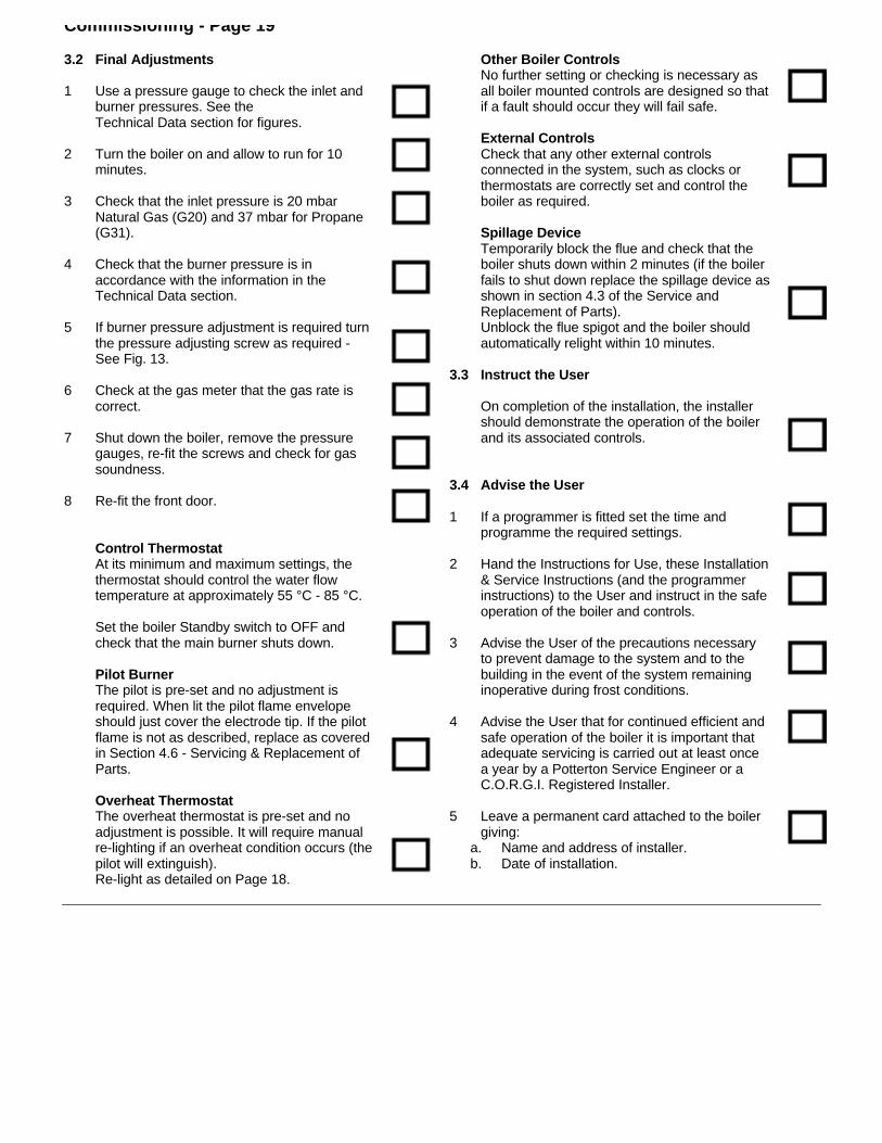
The system should be designed so that the maximum statichead does not exceed 30m and a minimum of 500mm. SeeFig. 6.
The pump should preferably be fitted in the flow, thoughinstallation in the return is acceptable providing care is takento ensure air is not drawn into the system due to thenegative pressure effects of the pump. Isolating valves mustbe fitted as close as possible to allow replacement withoutsystem draining.
Drain off taps should be fitted in the pipework close to theboiler and in the low points of the system.
Fully Pumped Systems
The pump must be wired directly to the terminal block(See Fig. 12) as it will allow the pump to be controlled bythe over-run device. This will ensure that the pump willcontinue to run after boiler shuts down thus preventingnuisance operation of the overheat thermostat.
Systems fitted with controls which allow the boiler tooperate when both the hot water and central heatingcircuits are closed i.e. mechanically operatedthermostatic control valves, must be fitted with a by-passcircuit capable of:-
1. Dissipating a minimum of 2kW.2. Maintaining a minimum water flow through the boiler
of 8 L/min.
A suggested method of meeting these requirements byusing a bathroom radiator fitted with two lockshieldvalves is shown in Figs. 6 & 7.
Diagrammatic layouts of a fully pumped open systemand a fully pumped sealed system are shown in Figs. 6& 7. The central heating should be designed as suchthat the minimum flow through the boiler is above 8L/min.
Sealed Systems (Fully Pumped)
Installation
The installation must comply with the requirements ofBS 6798: 1987 and BS 5449: 1990. The British Gaspublication "British Gas Specification for Domestic WetCentral Heating Systems" should also be consulted.
Safety Valve
A non-adjustable spring-loaded safety valve, preset tooperate at 3 bar (45lbf/in2) shall be used. It mustcomply with BS 6759: Pt 1. and include a manualtesting device. It shall be positioned in the flow pipeeither horizontally or vertically upwards and close to theboiler. No shut-off valves are to be placed between theboiler and the safety valve. The valve should beinstalled into a discharge pipe which permits the safedischarge of steam and hot water such that no hazardto persons or damage to electrical components iscaused.
Pressure Gauge
A pressure gauge incorporating a fill pressure indicator,covering the range 0 - 4 bar (60 lbf/in2) shall be fitted tothe system. It should be connected to the system,preferably at the same point as the expansion vessel.Its location should be visible from the filling point.
Expansion Vessel
A diaphragm type expansion vessel to BS 4814: Pt 1.shall be fitted close to the inlet side of the pump on theflow from the boiler before any valves. The connectingpipework should not be less than 15mm. Pipeworkconnecting the expansion vessel should not incorporatevalves of any sort. Methods of supporting the vesselare supplied by the vessel manufacturer. The nitrogenor air charge pressure of the expansion vessel shall notbe less than the hydrostatic head, (height of the toppoint of the system above the expansion vessel).
Installation Requirements - Page 10
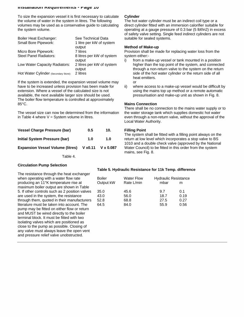
To size the expansion vessel it is first necessary to calculatethe volume of water in the system in litres. The followingvolumes may be used as a conservative guide to calculatingthe system volume.
Boiler Heat Exchanger: See Technical DataSmall Bore Pipework: 1 litre per kW of system
outputMicro Bore Pipework: 7 litresSteel Panel Radiators: 8 litres per kW of system
outputLow Water Capacity Radiators: 2 litres per kW of system
outputHot Water Cylinder (Secondary Store): 2 litres
If the system is extended, the expansion vessel volume mayhave to be increased unless provision has been made forextension. Where a vessel of the calculated size is notavailable, the next available larger size should be used.The boiler flow temperature is controlled at approximately85°C.
The vessel size can now be determined from the informationin Table 4 where V = System volume in litres.
Vessel Charge Pressure (bar) 0.5 10.
Initial System Pressure (bar) 1.0 1.0
Expansion Vessel Volume (litres) V x0.11 V x 0.087
Table 4.
CylinderThe hot water cylinder must be an indirect coil type or adirect cylinder fitted with an immersion calorifier suitable foroperating at a gauge pressure of 0.3 bar (5 lbf/in2) in excessof safety valve setting. Single feed indirect cylinders are notsuitable for sealed systems.
Method of Make-upProvision shall be made for replacing water loss from thesystem either:-i) from a make-up vessel or tank mounted in a position
higher than the top point of the system, and connectedthrough a non-return valve to the system on the returnside of the hot water cylinder or the return side of allheat emitters.or
ii) where access to a make-up vessel would be difficult byusing the mains top up method or a remote automaticpressurisation and make-up unit as shown in Fig. 8.
Mains ConnectionThere shall be no connection to the mains water supply or tothe water storage tank which supplies domestic hot watereven through a non-return valve, without the approval of theLocal Water Authority.
Filling PointThe system shall be fitted with a filling point always on thereturn at low level which incorporates a stop valve to BS1010 and a double check valve (approved by the NationalWater Council) to be fitted in this order from the systemmains, see Fig. 8.
Circulation Pump Selection
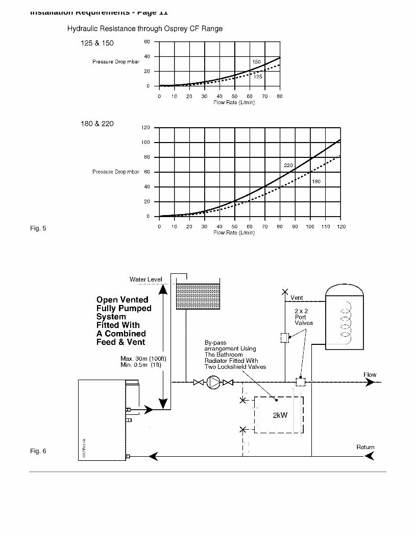
The resistance through the heat exchangerwhen operating with a water flow rateproducing an 11°K temperature rise atmaximum boiler output are shown in Table5. If other controls such as 2 position valvesare used in the system, the resistancethrough them, quoted in their manufacturersliterature must be taken into account. Thepump may be fitted on either flow or returnand MUST be wired directly to the boilerterminal block. It must be fitted with twoisolating valves which are positioned asclose to the pump as possible. Closing ofany valve must always leave the open ventand pressure relief valve unobstructed.
Table 5. Hydraulic Resistance for 11k Temp. difference
Boiler Water Flow Hydraulic ResistanceOutput kW Rate L/min mbar m
35.0 45.6 9.7 0.143.0 56.0 18.7 0.1952.8 68.8 27.5 0.2764.5 84.0 55.9 0.56
Installation Requirements - Page 11
Fig. 5
Fig. 6

Installation Requirements - Page 12
Fig. 7
Fig. 8

2. Installation - Page 13
2.1 Prepare the boiler
These instructions assume you have decided on where theboiler will be located.
1. Carefully unpack the boiler.
2. Do not discard any packaging until all the items areaccounted for.
3. Position the boiler to ensure the draft diverter is therequired distance from the wall.
4. Remove the top panel - 2 screws.
5. Remove the front door - unhook and lift off.
6. Fit the flue spigot (supplied separately inside the case)to the draft diverter.
Fig. 9

Installation - Page 14
Fig. 10
2.2 Connect the Gas Supply
1. Ensure that the gas supply is isolated.
2. Connect the gas supply to the gas cock using a 22mmcopper pipe, sliding it in from the back panel to the gascock.
The pipe diameter required will depend on the boilermodel and the pipe length from the gas meter. Ensurethat the gas supply pipe is selected in accordance withBS 6891 so that an adequate gas supply to the boiler isprovided.
Do not turn the gas supply on at this stage.
2.3 Connect the Water System
1. Connect system pipework to the boiler. Arrangepipework to ensure correct venting of pipes and boiler.
The pipe diameter required will depend on boiler modeland system design and may not be the same as boilerflow and return tappings.
Note: Drain off taps should be installed at the lowestpoints in the system.
The flow and return pipes on the boiler are made of steelwith a conical 11/4/" male thread.

Installation - Page 15
2.4 Connect the Power Supply Cable
1. The mains supply should be 230V 50Hz and fused at3A.
2. The mains wiring to the boiler has to be connectedinside the control panel
Access to the Control Panel Wiring Block
a. Open the top panel of the boiler by unscrewing therear screws.
b. Turn the blocking bracket 'A' to the inside of theboiler.
c. Open the control panel and turn as shown in Fig.11.
d. Remove the 2 screws 'B'.
e. Lift metallic strip to enable access to the wiringblock 'C'.
3. Cable clamping is provided on the side panel andcontrol panel. Feed the cables through the cable holderand clamps, and into the terminal connection.
Note: When connecting the power supply cable, ensurethat the length of the earth wire is such, that if thepower supply cable pulls out of the cable clamp the liveand neutral wires become taut before the earth wire.
4. The pump wiring should be routed as the mains wiring,through the cable clamps and connected to the terminalconnections PL and PN - Fig. 12.
5. Take up excess slack in the cables between theterminal block and the cable clamp, then tighten thecable clamp screws.Ensure sufficient slack is available to the cable clampsto allow the control panel to hinge freely. Check byopening the control panel.
6. Close the back panel of the control board and secureusing the two screws - see Fig. 12.
7. Close the control panel by turning it upwards andpushing it onto hinge D.
8. Carry out preliminary electrical system checks i.e. EarthContinuity, Short Circuit, Polarity and Resistance toEarth.
Frost Thermostat:If a Frost Thermostat is to be fitted, the connectionsshould be made in the wiring external to the boiler.
Do not switch on the electricity supply at this stage.
Fig. 11

Installation - Page 16
Fig. 12
2.5 Install the Room Thermostat
1. If a Room Thermostat is to be fitted, the connectionsshould be made in the wiring external to the boiler.
2.6 Install the flue
1. Install the natural draft flue according to BS 5440 andFig. 4.
2. The boiler is fitted with a spillage device that will trip theboiler out under adverse conditions.

3. Commissioning - Page 17
Fig. 13
Important
The commissioning and boiler adjustment must only becarried out by a suitably qualified personnel. PottertonMyson Ltd. offer this service on a chargeable basis.
Important
When purging and testing the gas supply for gassoundness open all windows and doors in the room.
Extinguish all naked lights, cigarettes, pipes, etc.

Commissioning - Page 18
3.1 Commission the Boiler
Open Vented Systems - Remove the pumpand flush the system thoroughly with coldwater. Re-fit the pump. Fill and vent thesystem then check for leaks.
Sealed Systems - The system can be filledusing a sealed system filler pump with a breaktank or by any other method approved by theLocal Water Authority. Refer to Section 1.6,'The System' on Page 9 of these instructions.
Remove the pump and flush the systemthoroughly with cold water. Re-fit the pump. Filland vent the system until the pressure gaugeregisters 1.5 bar (21.5 lbf/in2) and check forleaks. Raise the pressure until the safety valvelifts, this should occur within ± 0.3 bar of thepreset lift pressure of 3 bar. Release water toattain the correct cold fill pressure.
Step by Step Commissioning (tick box when done)
1 The whole of the gas installation must bechecked for soundness and purged inaccordance with BS 6891.
2 Check the water system for leaks and rectifyas necessary.
3 Preliminary electrical system checks must becarried out. They are:- Earth Continuity, ShortCircuit, Polarity & Resistance to Earth.
4 Re-fit the front cover and controls panel.
5 Set the rotary boiler switch on the usercontrols to its minimum position and boilerStandby switch to 'O' Off.
6 If a programmer is fitted, set to the 'Off'position.
7 Turn the boiler gas service cock to the 'On'position and then turn On the main gas supply.
8 Ensure the system is full of water and that thepump, radiator and any other isolating valvesare open.
9 Switch On the main electricity supply at theisolating switch or plug and socket.
10 If a programmer is fitted set it to the 'On'position and check that the room and cylinderthermostats, where fitted are set to hightemperatures.
11 i. Press control knob in lightly and turn. Align
off position with marker .ii. Press control knob in lightly and turn. Align
ignition position with marker .iii. Press control knob in firmly and hold, at the
same time press the ignition button. Thepilot flame should be visible at the pilotwindow. If not press the ignition button untilthe flame is established.
iv. When the flame is established hold thecontrol knob in for approximately 20seconds before releasing. The pilot flameshould remain alight.
v. Press control knob in lightly and turn, align
full flame position with marker .vi. Switch the boiler Standby switch to On.
12 With the main burner running, check for gassoundness around the boiler using leakdetection fluid.
13 Allow the system to reach maximum workingtemperature and examine for leaks. Set theboiler Standby switch to 'O' and drain thesystem whilst still hot.
Note: Should the boiler fail to operate correctlyrefer to the Fault Finding Guide on Page 26, and theboiler wiring diagram on Page 24 for furtherinformation.
14 Re-fill and vent the system making a final checkfor leaks.
On sealed systems adjust to the correct cold fillpressure. Set the pressure gauge pointer to thesystem design pressure.
If a by-pass circuit is fitted the by-pass valveshould be adjusted with the boiler operatingunder minimum load conditions to maintainsufficient water flow through the boiler toensure that the overheat thermostat does notoperate under normal conditions.
Commissioning - Page 19
3.2 Final Adjustments
1 Use a pressure gauge to check the inlet andburner pressures. See theTechnical Data section for figures.
2 Turn the boiler on and allow to run for 10minutes.
3 Check that the inlet pressure is 20 mbarNatural Gas (G20) and 37 mbar for Propane(G31).
4 Check that the burner pressure is inaccordance with the information in theTechnical Data section.
5 If burner pressure adjustment is required turnthe pressure adjusting screw as required -See Fig. 13.
6 Check at the gas meter that the gas rate iscorrect.
7 Shut down the boiler, remove the pressuregauges, re-fit the screws and check for gassoundness.
8 Re-fit the front door.
Control ThermostatAt its minimum and maximum settings, thethermostat should control the water flowtemperature at approximately 55 °C - 85 °C.
Set the boiler Standby switch to OFF andcheck that the main burner shuts down.
Pilot BurnerThe pilot is pre-set and no adjustment isrequired. When lit the pilot flame envelopeshould just cover the electrode tip. If the pilotflame is not as described, replace as coveredin Section 4.6 - Servicing & Replacement ofParts.
Overheat ThermostatThe overheat thermostat is pre-set and noadjustment is possible. It will require manualre-lighting if an overheat condition occurs (thepilot will extinguish).Re-light as detailed on Page 18.
Other Boiler ControlsNo further setting or checking is necessary asall boiler mounted controls are designed so thatif a fault should occur they will fail safe.
External ControlsCheck that any other external controlsconnected in the system, such as clocks orthermostats are correctly set and control theboiler as required.
Spillage DeviceTemporarily block the flue and check that theboiler shuts down within 2 minutes (if the boilerfails to shut down replace the spillage device asshown in section 4.3 of the Service andReplacement of Parts).Unblock the flue spigot and the boiler shouldautomatically relight within 10 minutes.
3.3 Instruct the User
On completion of the installation, the installershould demonstrate the operation of the boilerand its associated controls.
3.4 Advise the User
1 If a programmer is fitted set the time andprogramme the required settings.
2 Hand the Instructions for Use, these Installation& Service Instructions (and the programmerinstructions) to the User and instruct in the safeoperation of the boiler and controls.
3 Advise the User of the precautions necessaryto prevent damage to the system and to thebuilding in the event of the system remaininginoperative during frost conditions.
4 Advise the User that for continued efficient andsafe operation of the boiler it is important thatadequate servicing is carried out at least oncea year by a Potterton Service Engineer or aC.O.R.G.I. Registered Installer.
5 Leave a permanent card attached to the boilergiving:
a. Name and address of installer.b. Date of installation.

4. Service & Replacement of Parts - Page 20
Read these: To ensure continued efficient operation of the appliance, it is recommended that it is checked andcleaned as necessary at regular intervals.
The frequency of servicing will depend upon the particular installation conditions and usage but ingeneral once per year should be adequate.
It is the law that any service work must be carried out by a competent person who is C.O.R.G.I.Registered.
Before servicing, fire the appliance and check that the flames are blue. Yellow flame and excessive liftingindicate poor combustion.
WARNING: Before commencing work set the boiler standby switch to 'O' Off and allow the appliance to cool, isolatethe electricity supply.
If the gas valve is to be removed turn off the gas supply at the appliance service cock.
IMPORTANT: Always test for gas soundness after completing any servicing of gas carrying components and carry outfunctional checks of controls.
IMPORTANT: Ensure that the outer white case is correctly fitted.
Notes on Cleaning Boiler Components
Heat ExchangerPlace a sheet of paper under the heat exchanger (after removing the burner assembly) then using the brush (Suppliedwith the boiler), scrape the flueway fin surfaces in a downward movement. This will ensure that most of the deposits willbe collected on the paper.
BurnerBrush the burner top and check that the flame ports are clear. Any blockage may be removed with a fine wire brush.Turn the burner upside down and tap gently to remove any debris (Protect the electrode).
ElectrodeIf the electrode requires cleaning wipe the surface using a cleaning fluid.
Main InjectorsOmit this operation if the gas rate is correct, otherwise clean by blowing through. Do NOT clear the injectors with a pinor wire.
FlueInspect the draft diverter and flue tube for blockage, condensation and integrity, rectify if necessary.

Service & Replacement of Parts - Page 21
4.1 General Access
Warning: Before attempting to remove any component fromthe appliance first disconnect the mains electricity supply byremoving the plug from the wall socket or by switching offthe appliance at the external isolating switch and isolate thegas supply.
Note: The 'O' (Off) position on the boiler standby switch willleave parts of the boiler Live.
If the appliance gas valve is to be removed it will benecessary to isolate the gas supply at the appliance isolatingvalve.
Important: After removal or replacement of any gas carryingcomponent a test for gas soundness must be made andfunctional check of the controls carried out.
Re-assemble all parts in reverse order.
1. Remove the front door by pulling forward then lifting up,see Fig. 15.
2. Remove the top panel - 2 screws at rear, pull upwardsand lift off.
3. Lift control panel onto hinges, drop forward, remove 2screws and pivot forwards.
4. Lift off the metal shield.
4.2 Control Panel
• Gain General Access - See 4.11. Disconnect gas valve and boiler stat & TTB connector.2. On re-assembly refer to Fig. 12.
Fig. 14

Service & Replacement of Parts - Page 22
Fig. 15
Fig. 16
4.3 TTB Thermostat
• Gain General Access - See 4.11. Disconnect the TTB connector, unscrew the TTB
thermostat from the draft diverter and open the cableclamp. Unscrew earth connection, see Fig. 16.
2. Re-assemble in reverse order.
Note: This device is a safety feature and as such it shouldnot be disabled or interfered with. Only Potterton partsshould be used for replacement. If the unit continues to tripthen the flue should be checked for spillage. Always checkthe operation of the TTB after every service.
4.4 Boiler Thermostat
• Gain General Access - See 4.11. Open the control panel.2. Remove spring clip on the outside of the thermostat
pocket and pull it clear of the heat exchanger.3. Remove the user thermostat control knob.4. Unscrew the user thermostat, note the wire connections
(each wire is numbered) and remove the wires.5. Re-assemble in reverse order.
4.5 Overheat Thermostat
• Gain General Access - See 4.11. Disconnect the wires from the thermostat.2. Unscrew the thermostat from the conducting 'Pocket'.3. Re-assemble in reverse order.
4.6 Burner Assembly
• Gain General Access - See 4.11. Close the gas cock.2. Disconnect the gas pipe from the gas valve.3. Disconnect the wiring to the control panel and the
overheat thermostat.4. Remove the igniter.5. Unscrew the burner plate - 2 nuts.6. Remove the gas valve/burner assembly and lift over the
location peg.7. Pull the assembly forwards, check the condition of the
burner and thermocouple - replace if necessary.8. Re-assemble in reverse order.
Injector: Use a 12mm spanner to remove the injector,use a new sealing washer on re-assembly.

Service & Replacement of Parts - Page 23
4.7 Gas Valve• Gain General Access - See 4.11. Remove burner assembly - See 4.62. Disconnect gas valve lead.3. Unscrew pilot tube and thermocouple.4. Remove inlet and outlet plates.5. Re-assemble in reverse order.6. Check burner pressure and gas rate against the data
badge using the pressure test point and gas meter,shown in Fig. 13.
4.8 Pilot Interrupter• Gain General Access - See 4.11. Remove interrupter wires from overheat thermostat.2. Unscrew thermocouple.3. Re-assemble in reverse order.
4.9 Pilot Assembly• Gain General Access - See 4.11. Unscrew igniter.2. Unscrew thermocouple and pilot tube.3. Remove 2 screws and remove pilot assembly.4. Re-assemble in reverse order.
4.10 Burner• Gain General Access - See 4.11. Remove burner assembly - See 4.62. Remove burner insulation.3. Unscrew 3 screws in burner plate and remove burner.4. Re-assemble in reverse order.
4.11 Cleaning Heat Exchanger• Gain General Access - See 4.11. Remove burner assembly - See 4.62. Remove 4 wing nuts holding top panel on.3. Remove brush from holder and clean as required.4. Re-assemble in reverse order.
Note: If insulation is to be removed wet first to reduce fibrebreakdown.
Important: After any work carried out involving gas carryingcomponents a full gas soundness test procedure should becarried out in accordance with BS 6891.

5. Wiring Diagrams - Page 24
Fig. 17

Wiring Diagrams - Page 25
Fig. 18

6. Fault Finding - Page 26

Fault Finding - Page 27

Fault Finding - Page 28
Fig. 19

7. Short List Of Spare Parts - Page 29

7. Short List Of Spare Parts - Page 30
Item No. Catalogue No. Description Quantity G. C. No.
1 8000856 Gas Valve - SIT 1 E03-6502 8000854 Burner Bar - Polidoro A/R E03-6143 8000860 Injector A/R E03-6534 8000859 Injector Washer A/R E03-6525 8000909 Thermostat 1 E03-6836 8000871 Limit Thermostat 1 E03-7187 8000830 Pilot Burner 1 E03-6398 8000832 Spark Electrode 1 E03-6319 8000835 Pilot Injector 1 E03-64310 8000838 Thermocouple 1 E03-64211 8001171 TTB Spillage Thermostat Assembly 1 E03-685
Back Page