installation, operations and user’s manual095973ba7a9bfb39d656-eb4f2a56f8b42124408f8ba93d4… ·...
TRANSCRIPT

Fully Aboveground Instal lat ions
Part ial ly In-Ground Instal lat ions
Fully In-Ground Instal lat ions
INSTALLAT ION , OPERAT IONS AND USER ’ S MANUAL
Original Endless Pool
The entire Endless Pool system is ETL listed, Ref. #2001779 and conforms to UL Standard #1563. Individually, all electrical com-ponents of the Endless Pool are UL and/or CSA approved. As defined by the International Residential Code (IRC), the EndlessPool is considered an aboveground or an in-ground pool depending on the installation. That is to say, customers can install our End-less Pool Kit above-ground on a garage or basement floor or in the backyard or they can sink it partially or fully in-ground. The unitis completely self-supporting. As required by the IRC the Endless Pool meets all the following standards: ANSI/NSPI Standards#3 (Permanently Installed Residential Spas), #4 (Aboveground/On-ground Residential Swimming Pools), #5 (Residential In-groundSwimming Pools), and #6 (Portable Spas). The appropriate governing standard is dependent on the installation method and the re-quirements and definitions used by the local governing bodies.
All electrical connections should be made by a licensed electrician in accordance with the current national and local electrical codes.
All pool equipment including the 4 kW electric heater, circulating pump and 5 HP hydraulic power unit runs off one 30 amp, singlephase, GFCI protected, 220 volt service. A minimum of 10AWG wire should be used for all field wiring. We recommend you installa shut off within 5’ of where you intend to place your power unit.
Please read this Owner’s Manual and all associated Supplemental Guides prior to beginning your project.
Installation Instruction Booklet Information
Installation Instructions Table of Contents
Pool Arrival and Inspection . . . . . . . . . . . . . . . . . . . . . . . . . 2Site Preparation . . . . . . . . . . . . . . . . . . . . . . . . . . . . . . . . . . 2Assembly of Pool Panels (Overview) . . . . . . . . . . . . . . . . . 2Automatic Retractable Security Cover. . . . . . . . . . . . . . . . . 2Optional Insulation. . . . . . . . . . . . . . . . . . . . . . . . . . . . . . . . 2Liner Hanger . . . . . . . . . . . . . . . . . . . . . . . . . . . . . . . . . . . . 3Optional Liner Hangers . . . . . . . . . . . . . . . . . . . . . . . . . . . . 4Liner Underlayment . . . . . . . . . . . . . . . . . . . . . . . . . . . . . . . 5Liner . . . . . . . . . . . . . . . . . . . . . . . . . . . . . . . . . . . . . . . . . . . 6Thru-Wall Connections . . . . . . . . . . . . . . . . . . . . . . . . . . . . 7Swim Current Component Assembly. . . . . . . . . . . . . . . . . . 7Thru-Wall Connections . . . . . . . . . . . . . . . . . . . . . . . . . . . . 7Water Quality System. . . . . . . . . . . . . . . . . . . . . . . . . . . . . . 9Skimmer-Filter Installation . . . . . . . . . . . . . . . . . . . . . . . . 11Keypad Installation . . . . . . . . . . . . . . . . . . . . . . . . . . . . . . 14Power Unit . . . . . . . . . . . . . . . . . . . . . . . . . . . . . . . . . . . . . 14
Wiring. . . . . . . . . . . . . . . . . . . . . . . . . . . . . . . . . . . . . . . . . 15Bonding and Grounding . . . . . . . . . . . . . . . . . . . . . . . . . . . 18Heater/Controller . . . . . . . . . . . . . . . . . . . . . . . . . . . . . . . . 18Water Quality Isolation Cover . . . . . . . . . . . . . . . . . . . . . . 19Hydraulic Hose Connections . . . . . . . . . . . . . . . . . . . . . . . 19Optional Antenna Extension. . . . . . . . . . . . . . . . . . . . . . . . 19Optional Retractable Security Cover System. . . . . . . . . . . 20Optional UV Sanitizer . . . . . . . . . . . . . . . . . . . . . . . . . . . . 20Optional Treadmill . . . . . . . . . . . . . . . . . . . . . . . . . . . . . . . 20Optional Hydrotherapy Jets System. . . . . . . . . . . . . . . . . . 20Optional Underwater Lights System . . . . . . . . . . . . . . . . . 20Optional Corner Step . . . . . . . . . . . . . . . . . . . . . . . . . . . . . 21Optional Interior Stair . . . . . . . . . . . . . . . . . . . . . . . . . . . . 21Optional Swim Mirror . . . . . . . . . . . . . . . . . . . . . . . . . . . . 21Optional Synthetic Coping System . . . . . . . . . . . . . . . . . . 21Endless Pool Warranty . . . . . . . . . . . . . . . . . . . . . . . . . . . . 29
Operations and Maintenance Table of Contents
Overview . . . . . . . . . . . . . . . . . . . . . . . . . . . . . . . . . . . . . . 21Filling Your Endless Pool. . . . . . . . . . . . . . . . . . . . . . . . . . 21Pool Equipment and Startup. . . . . . . . . . . . . . . . . . . . . . . . 22Balancing the Pool Water . . . . . . . . . . . . . . . . . . . . . . . . . . 24How to Swim in an Endless Pool . . . . . . . . . . . . . . . . . . . . 25
Maintenance and Use of Your Endless Pool . . . . . . . . . . . 25Draining Your Endless Pool . . . . . . . . . . . . . . . . . . . . . . . . 26Winterizing Your Endless Pool. . . . . . . . . . . . . . . . . . . . . . 26Poolside Water Quality System Troubleshooting. . . . . . . . 27Keypad Functions and Troubleshooting. . . . . . . . . . . . . . . 28
1

1. Pool Arrival and Inspection
The Standard Endless Pool® arrives in three packages: a skid ofpool panels weighing approximately 850 lbs., a 4' x 8' x 4' highcrate weighing about 1,150 lbs and a pair of 6 5/8" wide steel re-inforcing channels. Most shipping companies will lower the con-tainers to the ground with a hydraulic lift gate on their truck. Thepool can remain in the containers until you are ready to begin in-stallation. Please contact our shipping department prior to ship-ment to answer any questions you may have. Since every deliveryis slightly different, and depends to a large extent on site condi-tions, it is important to speak with our shipping department wellin advance to reduce the chance of surprises.
Upon arrival, the packages should be inspected for external dam-age. Should there be visible damage, you must complete a dam-age-claim report provided by the truck driver. Please call theEndless Pools shipping department immediately at (800) 732-8660. The pool components are not damaged by freezing condi-tions and may be stored outside under a tarp for an extendedperiod prior to installation.
To begin installation, or to move pool components, begin un-packing the pool. Using a hacksaw or tin snips, remove the steelpacking straps encircling the pool panel skid. The wooden topand sides of the crate may be removed with a phillips-head screwdriver.
2. Site Preparation
It is important that your Endless Pool® be installed over asmooth, level concrete slab that is capable of supporting 260pounds per square foot. The thickness and the quality of the con-crete slab will affect the anchoring method.
If you are using the anchor bolt kit or you are installing a Custom Deeper Pool, then the floor must contain no voids orbumps and shall be relatively smooth and level. For customdeeper pools, the walls of the deeper section must also containno voids or bumps. The corners at the depth change should beeased slightly (approx 1/4"). Custom deeper pools must use theAnchor Bolt Kit. Anchoring the pool is discussed in more detaillater in these instructions as well as in a Supplemental Guide. Anoptional Tension Strap and Floor Leveling Kit is available forout-of-level or non-smooth sites.
If a new slab is poured, consult your local electrical codes regarding grounding and bonding. Many areas require a bonding wire to be attached to the reinforcing bar that is buriedin the concrete.
Drainage should be provided at the pool. It is ideal to install afloor drain in the area just outside of the front pool panel, but notdirectly under the panel or pool itself. In installations where thisis not possible, installation of a secondary containment system tohelp divert water to a more desirable location is recommended.Please call the Customer Service Department if you need any as-sistance in the design of a containment system.
It is extremely important to ensure that any water that may reachthe bottom flange of the pool panel, by splashing, run off, or ac-cidental leakage, be drained away immediately. With the bottomflange of the pool panel standing in water, corrosion may occurover time.
It is worth the time and effort now to install a drainage systemrather than be unprepared in the event of a mishap.
3. Assembly of Pool Panels
Provided with this Installation and User’s Manual will be the ap-propriate panel assembly Supplemental Guide for the Swim Cur-rent that has been chosen.
This Guide will take you through assembling the panels, anchoringthe panels, and drilling the appropriate holes into the panels. It iscritical that this Guide be referenced at this point. Any requiredhole must be drilled before proceeding with the installation.
4. Options
An Endless Pool® is usually customized to meet the needs of theend user. Pools of different lengths and widths are selected as wellas deeper pools. Naturally, the installation will vary depending onthe options selected so it is important to understand exactly whathas been supplied. On the day your pool ships, you will receive anemail with a customized owner’s manual containing the appro-priate Supplemental Guides for the options that were purchased.A hard copy of that same owner’s manual will be packaged in thepool crate. Please review all appropriate Supplemental Guide be-fore proceeding with the installation to ensure that selected op-tions have been considered.
Additionally, the placement of the Water Quality System keypad needs to be considered. The majority of our customer’splace the keypad in the coping of the pool. However the keypadcan be mounted in the skirting or on a nearby wall as an alterna-tive. Please refer to the Keypad Section of these installation in-structions for a more detailed description.
5. Automatic Retractable Security Cover
If you have purchased a Below Deck Automatic Retractable Se-curity Cover (BDARSC) then the installation must begin at thistime. The cover mechanism and bracket will be attached directlyto the pool panels.
The BDARSC must be mounted at the front of the pool. Aminimum of 24" horizontal clearance is required at the front ofthe pool for the Drive Mechanism. The combination in-wallcover track and liner hanger will raise the coping off the rein-forcing channel by 2-1/8". The coping or other finish materialcovering the front edge of the pool must be constructed so tonot interfere with the operation of the cover. At a minimum,access must be maintained in the finished work for the trackend guides at the front corners of the pool. Ideally, there shouldbe access to the entire cover mechanism.
For more detailed information on the assembly and installationof this option, please refer to the Below Deck Automatic Re-tractable Security Cover Supplemental Guide.
6. Optional Insulation (by others)
To conserve heat and reduce operating costs we strongly recom-mend that the Endless Pool be insulated with rigid foam. Simple2" thick rigid foam insulation boards are usually adequate and areavailable from any building supply house. Check with your supplierfor a recommended adhesive appropriate for the type of rigid in-sulation that they supply. Be sure to leave access to all of the panelcutouts when you are installing the insulation. Be sure to considerthe danger of freezing for any pipes running outside the insulation.
2

Refer to the appropriate Supplemental Guide if you pur-chased one of our optional Skirting Kits (Fig 6).
If you have selected the hydrotherapy jet option and yourpool is exposed to freezing conditions, please refer to Hy-drotherapy Jet Supplemental Guide for additional insulat-ing measures.
7. Liner Hanger
The aluminum liner hanger installs around the perimeterof the pool panel enclosure. The liner hangs from this ex-trusion using a bead that is heat welded into the top edgeof the liner. The liner hanger system is packaged in the pool.Self-drilling fasteners are included in the kit along with anut driver attachment for your drill (Fig 7).
Because the height of the 2 steel reinforcing channels isslightly higher than the surrounding top flange, we providePVC shims inside the kit to place under the liner hangerand to shim the hanger up to the level of the channels tokeep the whole system level. The shims can be cut with ahacksaw or scored with a utility knife and snapped to fit thesize of the pool. Over the channels, the fasteners should bedrilled through the channel and the flange. You may use apilot hole if you wish. Elsewhere, the fasteners must bedrilled through the shims and the panel flange.
Take the four 8' lengths of liner hanger that have beennotched in the center, and bend these pieces so that theywill fit and be secured in each corner. Measure to ensurethe corner piece is centered in the corner. Use two selfdrilling fasteners and PVC shims to secure the small cornerlength first, by drilling through the back corner of the linerhanger flange, then secure the rest of the hanger to the endand side panels, using shims when not securing through thechannel. The hanger pieces should be flush with the insideof the reinforcing channel and will protrude into the poolthe thickness of the channel everywhere else.
Once the corner lengths are secured, install the remainingtwo lengths of liner hanger along the side of the pool. Thesepieces vary in length, depending upon your pool size, sothey may need to be trimmed. It is important that the gapat any joint between two liner hanger pieces be no greaterthan 1/8".
Caulk the gap between the liner hanger and the panel toensure that no water falling on the top flange of the poolpanel can work its way down behind the liner. (With thesame objective in mind, later caulk the joint between thetop of the liner hanger and the coping that you install overthe entire top flange of the pool.)
3
18 " ABS SHIM OR
18 " GALVANIZED
STEEL REINFORCING CHANNEL
6 12 "
34 " SELF-DRILLING SCREW
GALVANIZED STEEL POOL PANEL
LINER HANGER
SILICONE SEALANT AROUND PERIMETEROF LINER HANGER, BY OTHERS
28-MIL PVC LINER
Fig. 6
Fig. 7

8. Optional Liner Hangers
Optional Bullnose Coping SystemTypically used when the pool is installed fully in-ground, theOptional Bullnose Coping System allows the installer to fin-ish with concrete and/or tile right up to the water’s edge. Thealuminum bullnose coping system acts as both a liner hangerand a finished edge. Endless Pools, Inc. supplies precut piecesto fit the specific pool size ordered. Included in the kit areradius corners and straight pieces to provide a finished look.These extrusions are fastened down to the top flange of thepool panels through the PVC shims and the reinforcingchannels in the same fashion as the regular liner hanger sys-tem. The installer is responsible for building a proper perime-ter substrate for the concrete or tile (Fig 9).
Optional Wood Receiver Coping SystemTypically used when the pool is installed fully in-ground, theOptional Wood Receiver Coping System allows the installerto finish with wood or synthetic decking right up to thewater’s edge. The aluminum Wood Receiver Coping Systemacts as both a liner hanger and a finished edge, which caneasily accept 2" wood coping. Endless Pools, Inc. suppliesprecut pieces to fit the specific pool size ordered. Included inthe kit are mitered corners and straight pieces to provide a
4
1Bend notched liner hanger into placeas shown. Repeat for all 4 corners.
2The ends of 2 adjacent liner hanger sections shouldmeet at this point. Repeat for the other side.
4
3 Cut the liner hanger with a hacksaw at the point where 2 sections overlap. Repeat at every point labeled "A."
Attach the liner hanger to the panelwith the provided self-drilling screws. Use 2 screws per notched section andapprox. every 18" along the sides.
A A
A
A
GALVANIZED STEEL POOL PANEL
28-MIL PVC LINER
BULLNOSE RECEIVER COPING WITH INTEGRAL LINER HANGER
612 "
21 2
"
25 16
"
SILICONE SEALANT AROUND PERIMETEROF COPING, BY OTHERS
Fig. 9
Fig. 8
7. Liner Hanger

finished look. These extrusions are fastened down to the topflange of the pool panels through the PVC shims and the re-inforcing channels in the same fashion as the regular linerhanger system. The installer is responsible for building aproper perimeter substrate for the decking material (Fig 10).
Optional Aluminum Coping SystemThe Endless Pools Aluminum Coping Option offers a con-venient method to finish off the top edge of your Endless Pool,either indoors or out. The coping, which also acts as a linerhanger, is 1-3/8" thick and comes in a sand textured white fin-ish. The pieces are precut to fit your pool size and fit securelyover the steel channel. The coping system is delivered with yourpool. It may be ordered later and shipped by UPS ground foran additional shipping charge. The kit’s weight depends on thepool size and comes in 5 boxes (Fig 11).
Each coping kit contains pre-fabricated corners and straightaluminum pieces cut to match your pool size. These cornersare either square or mitered based on your order. The 8" wideprofile of the coping makes it ideally suited for pools that arefreestanding or partially recessed. The coping is secured tothe top of the wall panel with tek screws, which are concealedbeneath the aluminum snap strip of the same finish as thecoping. As an alternative the 6-3/8" snap strip can be elimi-nated and a 6" accent tile can be installed. Joints between theadjacent coping pieces are covered with an aluminum coverstrip with the same finish as the coping.
The front panel will need to be extended or packed out withcustomer supplied finished materials to extend beyond theequipment mounted on the front panel. See Technical Spec-ification for details.
9. Liner Underlayment
If it is possible, finish the rest of the pool area, especiallythe ceiling over the pool, before proceeding. This will helpensure that the liner is not damaged, and also keep the poolwater, skimmer, and filter free of construction debris.
Vacuum the pool floor carefully, and make sure there are nosharp bumps that might damage the liner. Take special careto remove any metal chips that may have fallen on the floor.
If you have purchased the Anchor Bolt Kit, then that willcome with a roll of closed cell foam. Install the protectivefoam underlayment on the floor of the pool. The foam kitcomes in a box with the four foam corners and a can ofspray adhesive. The foam is 3.5' x 32'. For wider pools cutpieces as appropriate to cover the floor of the pool. Placeseams near the walls of the pool, so that they will be coveredby the Water Return Channels. Secure the foam to the floorwith the spray adhesive provided. With deeper pool instal-lations and larger pools, a second and sometimes even athird box of foam has been provided. Secure the foam tothe bottom and walls of the deeper area as well as to thefloor of the pool.
If you have purchased the Floor Leveling Kit, then that willcome with loose fill vermiculite and sheets of plastic floor-ing. The vermiculite will be used to level the floor filling invoids or covering bumps. The plastic floor will be cut to fitand placed over the vermiculite and will be taped to them-selves and to the base of the panels.
5
GALVANIZED STEEL POOL PANEL
28-MIL PVC LINER
WOOD/TILE RECEIVER COPING WITH INTEGRAL LINER HANGER
612 "
21 8
"
SILICONE SEALANT AROUND PERIMETER OF COPING, BY OTHERS
11 2
"
GALVANIZED STEEL POOL PANEL
28-MIL PVC LINER
ALUMINUM COPING WITH INTEGRAL LINER HANGER
ALUMINUM SNAP-IN STRIP
8"
1 14 "
612 "
11 2
"
ALUMINUM COPING CORNER DETAIL
LINER HANGER SUPPORT
TOP FLANGE OFGALVANIZED STEELPOOL PANELS
COPING
Fig. 10
Fig. 11
to be cut so they are 3" shorter than the panel height.
1/8" plastic sheets (cut to fit) if floor leveling kit was purchased or closed-cell foam (cut to fit) if anchor bolt kit was chosen.
Foam Corners
Liner Underlayment
Fig. 12

Do not attach foam to the steel walls of the pool. Securethe foam inserts in the 4 corners at the bottom. Foam cor-ners are not installed in the 4 corners of the deeper sectionof a custom deep-end pool (Fig 12).
10. Liner
Standard flat bottom pool liners are usually packaged in acardboard box in the pool crate. Liners for deeper pools andcustom-sized pools are sent separately by UPS Ground.Check to see if your liner was backordered at the time ofshipment. If you have any questions call Customer Serviceabout the status of your liner.
All work around your pool should be completed before youinstall your liner. Take a moment to be sure you have allnecessary work completed. Prepare for the liner installation.Be sure that the liner hanger, corners, panel joints and panelto base material are sealed with silicone. Tape off all holesin the pool wall (lights, jets and front panel holes) from theoutside. Place a vacuum hose through the highest thru-wallcutout or leave a small section of liner bead out of the linerhanger and insert the vacuum hose down from the top.Make sure that the vacuum hose opening is sealed with ducttape. The hose should be 3" - 4" off of the bottom of thepool floor foam (Fig 13).
Install the liner by starting at the center of the front panel.Spread the liner in the pool enclosure. Shoes should be re-moved for this and all future work in the pool to avoid dam-aging the liner. Find the vertical seam in the liner and centerit at the front of the pool. Place the four bottom corners ofthe liner in the four corners of the pool. While standing inone corner, fit the top bead of the liner into the slot in theliner hanger. For easiest install, fit the liner bead at bothcorners of an end of the pool, then fit the other two cornersat the opposite end. Work your way around the pool, fittingthe bead evenly into the hanger. We recommend not endingin a corner. Smooth the liner on the floor, pushing anywrinkles toward the walls (Fig 14).
After verifying that the vacuum hose is off of the bottom,turn the vacuum on. When the liner is drawn back, checkto see that the corners are positioned properly. If not, turnthe vacuum off and reposition the liner. With the vacuumrunning, smooth out all of the wrinkles. When you are sat-isfied with the placement of the liner, start to fill with water.
Keep the vacuum running until there is about 6" of waterin the shallowest portion of the pool. Turn the vacuum offand remove all tape and the vacuum hose. Do not fill be-yond 6" at this time.
Included in the box with the liner are No Diving signs.Please post these in prominent locations around the pool.The Endless Pool is shallow and must never be used fordiving. Diving into the pool is a very serious hazard andthese stickers are intended to warn children of the risks.Naturally, adult supervision is also critical whenever chil-dren use the pool.
6
4
3
2
1Seal any hole in the panels with duct tape (from the outside)
Seal the liner hanger, panel seams, and where the panels meet the floor with silicone
Feed the vacuum hose through the top-most hole in the panel.
Make sure the end of the vac hose is at least 3" off of the floor.
Fig. 13
Vinyl LinerVertical seam of liner centered on the front panel.
Fig. 14

11. Thru-Wall Connections (Part 1)
This step only should only be followed if the Optional Hydraulic Treadmill or Optional Hydrotherapy Jets is beinginstalled. Otherwise, proceed to the next section.
Hydraulic Treadmill:
If you are installing a hydraulic treadmill then the thru-wallfittings for that option will have to be installed at this time.Use a sharp utility knife to cut a round hole in the liner,using the hole in the panel as a template. Install the thru-wall fitting as shown in Fig 15.
Proceed to next section.
Hydrotherapy Jets:
If you have purchased the hydrotherapy jet option and youhave cut the holes in the panel for the jet suction in the“Ideal” location (10” up from base of the panel), then theyhave to be installed at this time as well. Use a sharp utilityknife to cut a round hole in the liner, using the hole in thepanel as a template. Install the suction thru-wall fitting asshown in Fig 16. Repeat this process for the remaining jetsuction fitting.
The plumbing between the suction fittings and the jetpump should be completed prior to starting to fill again asdetailed in the Jet Supplemental Guide. Once this is completed, close the ball valve. This will allow you to continue filling the pool without having to plug the suctionfittings from inside the pool.
Once this is completed, proceed to the next section.
12. Swim Current Component Assembly
Provided with this Installation and User’s Manual will bethe appropriate Supplemental Guide for the type of SwimCurrent that has been purchased.
This guide will take you through the assembly of the pri-mary internal components of the pool. Additional Supple-mental Guides will be provided, and will have to bereferenced, should any optional internal components (eghydraulic treadmill, corner steps, bench seats, etc.) havebeen purchased.
13. Thru-Wall Connections (Part 2)
Once the water level is three inches below the next lowestthru-wall (above the benches), stop filling the pool so thatthe remaining holes in the liner can be cut. At a minimumthere are four holes to be cut; the Water Quality Systemsuction & return and the Swim Current high & low-pres-sure hydraulic lines. Note: if you are installing an Elite orDual Propulsion Endless Pool, then there will be two sets(total of 4) hydaulic lines. Use a sharp utility knife to cut around in the liner, using the hole in the panel as a template.Install the thru-wall fitting as shown in Fig 18.
7
(Suction cover must be screwed to fitting prior toinstalling)
Jet SuctionFitting
Rubber Gasket
Pool Liner
Rubber Gasket
Pool Panel
Cork Gasket
VGB ApprovedSuction Cover
Lock Nut
Rubber Gasket
Rubber Gasket
Thru-Wall Fitting
Pool Liner
Pool Panel
Lock Nut
Cork Gasket
Fig.15
Fig. 16
Swim Current High-Pressure Fitt
Swim Current Low-Pressure Fitt
Water QualitySystem Return Fitting
Water QualitySystem Suction Fitting
Fig. 17
Rubber Gasket
Rubber Gasket
Thru-Wall Fitting
Pool Liner
Pool Panel
Lock Nut
Cork Gasket
Fig. 18

The hose with the red tape wrapped around the fitting isthe low-pressure hose and should inserted into the lower ofthe two swim current thru-walls. The high-pressure hose isto be inserted into the higher fitting.
Install the Water Quality System pre-plumbed thru-wallassemblies as shown in Fig 19. Make sure to secure one ofthe insert elbows into the Water Quality Suction fitting.The elbow must be facing down and away from the propul-sion housing (Fig 20).
Optional Underwater LED Lights
If the optional underwater LED lights have been pur-chased, then the lens barrel should be installed at this timeas well. Use a sharp utility knife to cut a round in the liner,using the hole in the panel as a template. Install the lensbarrel as shown in Fig 21.
Optional Hydrotherapy Jets
If the jet suction holes in the panel have been cut the panelin the “Alternate” position (above the benches) then installthat fitting at this time. Use a sharp utility knife to cut around in the liner, using the hole in the panel as a template.Install the thru-wall fitting as shown in Fig 16.
The plumbing between the suction fittings and the jetpump should be completed prior to starting to fill again asdetailed in the Jet Supplemental Guide. Once this is com-pleted, close the ball valve. This will allow you to continuefilling the pool without having to plug the suction fittingsfrom inside the pool.
The four jet fittings can now be installed as well. Use asharp utility knife to cut a round in the liner, using the holein the panel as a template. Install the thru-wall fitting asshown in Fig 22.
Before installing the four jets, refer to the Endless Pool JetHydrotherapy Supplemental Guide. The 1/2" venturi piping will need to be secured to the jet body prior to permanently installing them.
8
Jet Bulkhead
ClearGasket
Pool Liner
WhiteGasket
Pool Panel
JetBody
Clear GasketLight Lens
Pool Liner
Pool Panel
LensLocknut
Pre-plumbed thru-wall assemblies
WQSReturnWQS
Suction
(Red tape wrapped around the fitting)
Attach insert elbow to the suction thru-wall prior to securing to the pool wall
High-Pressure Hose
Low-Pressure Hose
Fig. 19
Fig. 20
Fig. 21
Fig. 22

14. Water Quality System
Note: If you have purchased the Optional UV Sanitizer,then refer to that Supplemental Guide at this time as theseinstructions will have been modified to accept this option.
The Water Quality thru-wall assemblies should be installedby this point. Attach the pre-plumbed suction assembly tothe suction thru-wall. Make sure to wrap Teflon tapearound the threads of the adapter that is glued into thethru-wall. The union of the pre-plumbed suction can betaken apart to make this step easier (Fig 23).
Attach the circulating pump to the bottom of the pre-plumbed suction assembly. Make sure that the pump uniono-ring is seated properly prior to installing (Fig 24).
Next attach the pump-to-heater pre-plumbed assembly tothe pump as shown. Again, make sure that the pump uniono-ring is seated properly prior to installing (Fig 25).
9
Pump Union O-Ring
Circulating Pump
Pre-plumbedSuctionAssembly
Pump to HeaterPre-plumbed Assembly
Pump Union O-Ring
Fig. 23
Fig. 24
Fig. 25

This next step is best done with a helper. Align the heater-controller with the pump-to-heater pre-plumbed assembly.Make sure the T-gasket is seated properly prior to tightening the heater-controller union nut. The raise section of the T-gasket will sit in the groove of the tailpiece.Once the heater-controller is securely attached to theplumbing, makes sure that it is level. Use the provided self-drilling screws to attach the mounting board to the Z-brace (panel stiffener). Use a minimum of 2 screws.When the mounting board hits more than one Z-brace, attach with two screws along the top. In the instances whenit lands on only one Z-brace, attach with one screw alongthe top and one screw through the bottom slotted tab as shown in Figure 26.
At the outlet of the heater-controller attach the singleheater-controller tailpiece. Again, make sure the T-gasketis seated properly prior to tightening the heater-controllerunion nut (Fig 27).
Attach the pre-plumbed return assembly to the WaterQuality System thru-wall. Make sure to wrap Teflon tapearound the threads of the adapter that is glued into thethru-wall. The union of the pre-plumbed return can betaken apart to make this step easier.
Take a measurement from the edge of the heater-controllertailpiece to the vertical pipe of the pre-plumbed return as-sembly. Add 1-1/4" to that dimension (the 1-1/4" is thedepth of the tailpiece socket. Transfer this total dimensiononto the provided flexible PVC and cut it to that length.Use the provided PVC cleaner and cement to glue the cutpipe into the tailpiece socket. Make sure to apply cleanerthen cement to both faces of the glue joint.
10
T-Gasket
Heater-ControllerTailpiece
Heater-Controller Assembly
A mimimum of 2 screws should be used to attach assembly to the panel Z-Brace
T-Gasket
1-1/4" = the depth of thetailpiece socket
1-1/4"
Tailpiece
X+ 1-1/4’’
Fig. 26
Fig. 27
Fig. 28

11
14. Water Quality System (cont.)
Cut the excess pipe off of the pre-plumbed return assemblyso that the end of the vertical pipe is just above the top mostedge of the horizontal pipe (Fig 29).
Finally, glue the slip x slip elbow onto both the vertical andhorizontal pipe. Make sure to apply PVC cleaner then ce-ment to both faces of each glue joint. Either the heater-controller union or pre-plumbed return assembly union canbe broken to make this step easier (Fig 30).
15. Skimmer-Filter Installation
If not done so already, attach the PVC angle bracket to the right side of the propulsion housing with the provided screws (Fig 31).
These connections can be undoneto make gluing elbow into place easier
x2B
Fig. 29
Fig. 30
Fig. 31

15. Skimmer-Filter Installation (cont.)
Remove the lock ring from the filter body. Loosely place theskimmer body into the shroud top. Re-install the lock ring.The lock ring should be tightened to the point where theskimmer body is seated firmly against the shroud top, butloose enough so that the skimmer body can rotate (Fig 32).
Glue the PVC straight nut into the "IN" port at the bottomof the skimmer body. Glue the 1-1/2" slip x 1-1/2" femalepipe thread adapter into the "OUT" port. Then thread thesuction fitting into the straight nut and thread the insertelbow into the adapter (Fig 33).
Attach the skimmer-filter shroud side to the shroud top with the provided screws as shown. The elbow attachedto the bottom of the skimmer is to be closer to the housing.Spin the shroud top (pre-attached to the skimmer-filter) as necessary (Fig 34).
12
Lock Ring
Glue joint
Apply Teflon Tape to threadsprior to installing
"IN" Port"OUT" Port
1/2" Stainless 1/2" Stainless Steel ScrewSteel Screw
Fig. 32
Fig. 33
Fig. 34

15. Skimmer-Filter Installation (cont.)
Connect the provided suction hose to the two insert elbows(1 attached to the skimmer-filter and 1 attached to the thru-wall fitting). Secure the hose with the provided plastichose clamps (Fig 35).
Note: If installing into a Dual Propulsion Pool, then the skimmer-filter assembly will be attached to the rightpropulsion housing.
Next, insert each of the tabs in the bottom of the shroudinto its corresponding slot in the wing cap. The excess hoseshould be place behind and to the right of the skimmer-filter body.
Secure the shroud top to the PVC angle bracket with theprovided 1/2" stainless steel screws (Fig 36).
Restart filling the pool. Once the water level is just belowthe Housing Lid, temporarily remove the Housing Lid. Usethe provided 1" self-drilling screw to attach the housing tothe pool wall. Make sure to wrap the bond wire (exiting thetop of the housing) around one of the screws prior to tight-ening (Fig 37).
If you have purchased a Raised Rear Bench Seat, then thatoption should be installed at this time as well. Refer to theRaised Bench Seat for a 48" & 54" Pool for more detailedinformation.
After the the Skimmer-Filter has been installed, continuefilling the pool until the top row of the honeycomb grill (ofthe propulsion housing) has been covered.
13
Tabs of shroud side are to be inserted into slot in wing caps
Connect the suction hose to each insert elbow prior to placing skimmer-filter assembly
Wrap bond wire around mounting screw prior to tightening
1/2" Stainless Steel Screw
Position suction hoseinside skimmer-filter housing as shown
Fig. 35
Fig. 36
Fig. 37

14
16. Keypad
Additionally, the placement of the keypad needs to be con-sidered. The majority of our customers place the keypad inthe coping at the front of the pool. However, the keypad canbe placed anywhere in the pool coping or the outside verticalfinish. The only constraint is the length of the cord betweenthe keypad and the poolside water quality system.
When installing the keypad, drill two 1" diameter holes at2-5/8" from center to center. Then with an appropriate saw,cut out the piece between the two holes.
Next, peal off the adhesive protection on the backside of thekeypad. Feed the keypad cord through the cutout. Firmlypress the keypad into place. Then, feed the bracket throughthe cord and push the bracket all the way up to the undersideof the coping. Make sure that the bracket is placed over thetwo threaded studs on the back of the keypad. Once that iscompleted, thread the two wing nuts over the threaded studsand hand tighten them.
If you are going to have your keypad in a horizontal surfacethat is deeper than the threaded studs, then simply cut yourholes, remove the adhesive protection, feed the cord into thehole, and firmly press the keypad into place. When pickinga location for the keypad in your finish work, it is importantto make sure it is within 10' of the Heater/Controller.
17. Power Unit
The power unit should be placed on flat and level surface. Ifthe power unit is to be placed outside, we recommend selectingour Outdoor Power Unit with Weather Guard to protect itagainst everyday elements. Whether placed indoors or out-doors, this is an air-cooled unit and must have ample ventila-tion. Therefore, a minimum of 12" of air spaced must beprovided on all sides of the power unit. In addition, the powerunit needs to be check periodically for maintenance andshould be accessible.
The power unit is heavy; take care when placing the power unit.
Once the power unit is in place, connect the run hoses. Thelow-pressure hose, lowest hydraulic hose on the front panel,gets connected to the connection on the black fill cap. Thehigh-pressure hose gets connected to the fitting on the high-pressure manifold (Fig 39).
Endless Pools, Inc. supplies a special vegetable-based hydraulicfluid created for this application and this equipment. Do notuse a substitute hydraulic fluid. Extra hydraulic fluid is pro-vided for longer hose runs. Any excess fluid should be retainedfor future use.
Make sure that the power is turned off to the power unit. Re-move the fill black fill cap and remove the oil filter by liftingit out of fill opening. Use the provided paper funnels and fillthe reservoir to with in 2" of the top. Once filled, replace theoil filter and ensure that it is seated properly before puttingthe fill cap back on. If you have selected a longer run hose, wehave provided extra fluid. In this case, turn the unit on and letit run for one minute to fill the run hoses. Turn the power off,remove the fill cap and oil filter, and add fluid as needed.Again, you want to fill the reservoir to within 2" of the top.
The power unit controller comes equipped with an automatictimer shutting off the system 30 minutes after receiving its lastcommand. Because the controller “remembers” the last speedat which is turned off, it will return to that same pace when itis turned back on.
2 5/8''1''
Gasket with adhesive
1''25,4mm
1''
1''25,4mm
2 5/8''66mm
Fig. 38
WirelessController
Antenna Connection
Fill Cap
Low-Pressure Connection
High-PressureConnection
Fig. 39

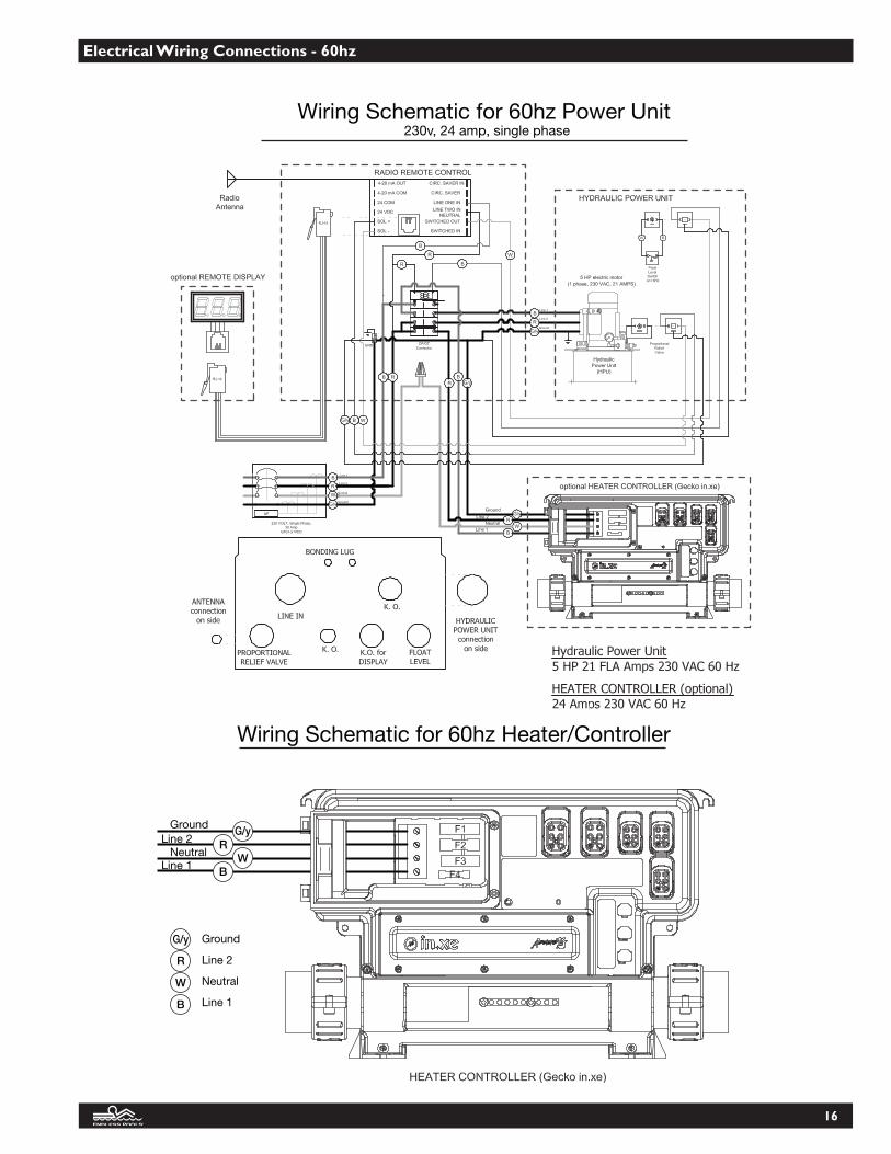
18. Electrical Wiring Connections - 60hz
The following is for the U.S. and countries with a similar power supply.
One 220 volt 30 amp GFCI circuit is all that is required to operate the Endless Pool. A minimum of 10AWG wire should be usedfor all field wiring. All connections should be made by a licensed electrician. An electrical whip to connect the power unit to theheater/controller is provided. The length of this whip is based on the length of your hydraulic hose specified in your order
We recommend that you have your electrician install a shut off within 5' of where you intend to place your power unit. You canhave your electrician install this prior to your pool being delivered.
Power is supplied to the system by connecting the existing whip on the power unit control box to the shut off installed by your elec-trician.
Power the poolside heater controller by connecting the whip supplied to both the power unit control box and the heater-controllerthrough the appropriate knockouts in these respective units. Specifically, inside the power unit control box, connect the black wire toterminal R2 on the line (left) side of the contactor, connect the red wire to R3 on the load (right) side of the contactor, connect thegreen wire to the ground bus bar, and the white wire junctions with the white wire coming from the shut off using a wire nut.
Connect the heater controller by attaching the black wire to the L1 terminal, the red wire to the L2 terminal, the white wire to theN terminal, and the green wire to the G terminal.
19. Electrical Wiring Connections - 50hz
The following is for the U.K. and countries with a similar power supply.Two 220 volt 30 amp RCD circuits are required to operate the Endless Pool. A minimum of 10AWG wire should be used for all fieldwiring. All connections should be made by a licensed electrician. We recommend that you have your electrician install one shut off within 5' of the location of your hydraulic power unit and anothershut off to accommodate the heater/controller installed on the front panel. You can have your electrician install this prior to your poolbeing delivered. Please consult all appropriate national and local codes.Power is supplied to the hydraulic system by connecting the existing whip on the hydraulic power unit control box to the shut off in-stalled by your electrician.Power to the poolside heater controller is supplied by connecting the second shut-off and the heater-controller through the appropriateknockouts in these respective units. This must be hard wired.Once the Water Quality System has been installed and your electrician has completed the wiring, you should install the Water QualitySystem Cover. Place the cover over the entire water quality system. Use the screws provided to attach the cover to the mounting plate.
15
16
Electrical Wiring Connections - 60hz

17
Electrical Wiring Connections - 50hz

18
20. Bonding and Grounding
All of the electrical equipment that we supply is UL or CSA ap-proved and must be installed in accordance with local electriccodes by a licensed local electrician. Bonding and Grounding isan important part of that process. All electrical components havebonding lugs and should be bonded together and to the steelpool panels. A bonding conductor shall be solid copper notsmaller than 8 AWG and may be insulated, covered or bare. Ifnew construction is involved where reinforcing rods are installedin the concrete under or adjacent to the pool this should be in-cluded in the bonding circuit. Each of the pieces of equipmentshould be separately grounded.
A #8AWG bare copper wire and bonding kit will be providedin the hydraulic hose/electrical whip box. This wire will be thesame length as your electrical whip. Connect this wire to yourpower unit and run it, with your hydraulic hose and whip, to thefront of the pool. Inside the bonding kit there will be a machinescrew and nut, a bonding lug, and a drill bit. Attach the bondinglug to the Z brace just under the heater controller. Feed thebonding wire through the bonding lug on the Z brace, throughthe opening in the heater controller mounting board, and con-nect it to the bonding bar on the heater controller.
21. Heater-Controller Plug-In Connections
The Heater-Controller (In.xe) features in.links connectors withcolored and tagged polarizers. This plug and connector technol-ogy has been specifically designed for easy and safe assembly.The tags are interchangeable depending on the output; the po-larizers are designed to avoid misconnections.
In.link connectors are easily and conveniently accessible fromthe front of the Heater-Controller offering a wide range of pos-sible connection configurations. In.link connectors come in 3sizes (HC, LC and low voltage) for all types of inputs and outputdevices.
They all include an integrated latch that keeps them safely in place and provides audible and tactile feedback when properly connected.
Finally, colored and tagged polarizers provide a definite advan-tage in easily configuring output devices. Refer to Figure 41 forspecific connections for the provided equipment.
Tabs of shroud side are to be inserted into slot in wing caps
Connect the suction hose to each insert elbow prior to placing skimmer-filter assembly
Fig. 40
Fig. 41 Jet Pump FuseUnused Fuse
Circulation Pump and UV FuseTransformer Fuse
Jet PumpConnection
UnusedConnection
Circulating PumpConnection
UV Connection
Unused Connection
Lights Connection
Keypad Connection

22. Water Quality System Isolation Cover
Now that the Water Quality System has been installed andyour electrician has completed the wiring, you should installthe Water Quality System Cover. Place the cover over the entire water quality system. Use the provided 1/2"screws to attach the isolation cover to the heater controllermounting board (Fig 42).
23. Hydraulic Hose Connections
Install the long hydraulic hoses between the Power Unit andhydraulic hoses at the front of the pool. These hoses are sup-plied by Endless Pools, Inc. to the length specified. Oftenthey are not shipped with the pool as the exact length is un-known at the time of shipment. Please order these hoses aweek before they are needed to allow shipment by UPSground. Two hoses up to 25 feet in length are supplied at noadditional charge. It is best to use hoses close to the lengthyou need rather than simply going with the standard 25 feet.There is an additional charge for lengths in excess of 25 feet.
Remove the protective plugs and connect the 2 hydraulichoses to the 2 ports on the Power Unit and tighten firmly.Do not over-tighten. The hose connecting to the fill cap onthe Power Unit is the return (low pressure) hose, which getsconnected to the lowest hydraulic hose at the front panel.The high-pressure hose, which is connected to the fittingon blue high pressure manifold, connects to the higher hoseat the front of the pool*. Adapters have been provided inthe hydraulic hose/electrical whip box to connect the hy-draulic run hose to the hoses penetrating the front panel.The hoses that go through the panels are a smaller diameterthan your run hose, you will find adapters in the ElectricalWhip box to make these connections. If the hoses you or-dered are too short and you need longer hoses, call Cus-tomer Service. Extra care should be taken that these hosesare cushioned when they pass by anything that could rever-berate. This will ensure a quieter installation. Use simplepipe insulation and clips for this purpose.
*See Figure 45 on page 20.
24. Optional Antenna Extension
Your swim current remote operates by radio waves. Shouldthe power unit be placed far away from your pool, the re-mote control may not operate efficiently. In order to correctthis, you should install the Antenna Extension Kit.
If your antenna has already been installed, disconnect itfrom the side of control box. Install the antenna extensionwire finger tight onto the control box connection. Once theantenna has been positioned closer to the pool, connect theother end of the extension wire to the antenna. Should youneed a longer wire than what was provided, you can pur-chase coaxial cable locally.
19
21
Tabs of Isolation cover will nest into the slots of the Mounting Board
Secure Isolation Coverto the Mounitng Board with the provided 1/2" screws
Fig. 42

25. Optional Retractable Security Cover Systems
Our most popular option and strongly recommended, the Re-tractable Security Cover system protects children and pets fromthe pool while keeping in temperature and humidity. With someinstallations, suitable access for this roll-up cover system is com-plex and should be discussed with an Endless Pool design profes-sional during the planning stage. The Supplemental Guidedescribes the cover installation more fully. If your pool is to beoutside, we can provide you with a cover pump to remove any rainwater that may accumulate.
The most popular configuration for this system is to have thecover roll off the rear of the pool. Other alternatives are possibleif space is limited. These are discussed in more detail in the Sup-plemental Guide. The kit includes the roller mechanism for thewidth of pool purchased, appropriate lengths of track, an alu-minum leading edge, and the rugged fabric which floats on thewater surface suspended between the parallel tracks. Two steelbrackets to mount the roller mechanism at one end of the poolare available.
The optional Retractable Security Cover system is manually pow-ered. We believe that this system is optimal for our compact pooland when installed correctly provides a simple means of coveringthe pool.
The aluminum track on either side of the pool is a requirement ofthe retractable security cover option. Covering this track is possiblebut increases complexity and will add to the cost of installation.
Optional Automatic Retractable Security Cover SystemOffered in two versions, the Automatic Retractable Security CoverSystem is rapidly becoming one of our most popular options. Op-erated with the turn of the key, the cover retracts easily making itideal for people who want the convenience of automation or lackthe strength to operate one manually.
The Below Deck version can be fully integrated into any custom
finish. The cover mechanism must be mounted at the front of thepool. Please refer to the Supplemental Guide for more informa-tion on this option.
The Above Deck can be mounted at either the front or the backof the pool and is compatible with any of our coping options. TheAbove Deck version comes with a convenient bench cover offeredin a variety of colors to compliment any decor. Please refer to theSupplemental Guide for more information on this option.
Optional Solar Blanket Roll Up SystemEndless Pools, Inc. supplies a Solar Blanket for all Endless Poolsizes, if the Retractable Security Cover has not been chosen. Forthose who wish it to serve as a permanent cover, a simple PVCpipe may be used to roll up the blanket for storage when the poolis in use. For this purpose, we supply PVC clips and PVC pipelong enough for your pool width. Depending on the width of thepool the PVC pipe will come in one or two pieces with a couplingattached to one end of the one piece of pipe. Using the PVCcleaner and PVC cement you received in your plumbing kit, glue the second piece of pipe into the open end of the coupling.Alternatively, the roller mechanism from the retractable securitycover may be used in conjunction with a length of 3" diameterPVC pipe to roll up the blanket. This optional solar blanket roll up system is available from the Endless Pools, Inc. CustomerService Department.
26. Optional UV Sanitizer
Ultra-violet water purifiers provide a chemical-free method ofmaintaining your pool by destroying organic pollutants as the waterpasses through the treatment chamber. This reduces the need forchemical sanitizers such as chlorine. Our UV system is particularlysuitable for users who are sensitive to the usual swimming pool dis-infectants, heavy metals from ionic purifiers or allergic to chlorine.
UV still needs to be used in conjunction with a sanitizer to “burnoff ” the dead organic matter killed by the UV system. We recom-mend simply using trace amounts (0.5 - 1 ppm) of regular household bleach, such as Clorox or other generic brands. This level is lower than the EPA recommended chlorine level fordrinking water.
27. Optional Treadmill (Manual or Hydraulically Driven)
Turn your Endless Pool into a complete home gym with the ad-dition of an Aquatic Treadmill.
Use the treadmill with the current on or off to vary the intensityof your walk or jog. Take it to the next step and use the aquatictreadmill to cross-train in the Endless Pool. Alternate betweenswimming and walking or jogging to get a full body workout! Ournew Aquatic Treadmills offer a spacious 20" wide belt for walkingor running. Both manual and hydraulically powered versions areavailable. Our underwater treadmills are typically installed in poolswith deeper panels.
28. Optional Hydrotherapy Jets System
By providing a supplementary pump that is operated by the heatercontroller and using the secondary suction and four venturi-typejets through the wall of an Endless Pool, the user can enjoy thetherapy benefits of jets in addition to the variable speed swim cur-rent. Installation is relatively straightforward but roughly doublesthe plumbing work required. The kit provided by Endless PoolsInc, includes everything necessary with the exception of the 1-1/2"schedule 40 PVC pipe. Detailed instructions are included in theSupplemental Guide along with a typical layout drawing. Whenjets are installed it is important to leave access to the outside of thepool panel for service. The holes for the jets should be cut beforeinstalling the liner. If the pool is located outdoors where freezingis an issue, care must be taken with the jet system plumbing. Ad-ditional insulation should be considered under these conditions.Call Customer Service with any questions about this limitation.
29. Optional Underwater Lights System
Underwater Lights are an important aesthetic option. Typicallylocated on either the side or the end wall of the pool, these twolights thread into in niches that are installed after the liner is inplace. The holes for these niches are cut using the holesaw pro-vided before the foam and the liner are installed. Directions comewith the lights which are packaged in the pool crate. These direc-tions are also found in the Supplemental Guide. Each light con-sists of a dry niche which serves as a porthole. The low-voltagelight threads into this porthole outside the pool. For outdoor in-stallations a weather resistant can is provided for added protection.A 22' cord connects these lights and plugs directly into the heatercontroller. The lights are then operated by the pool-side controls.
20

30. Optional Corner Step
To assist with access to the Endless Pool, optional Corner Stepsare available inside the Endless Pool in any of the four corners.For a more complete discussion about access to an Endless Poolplease refer to the Planning Guide. These optional steps are ap-proximately 11” high and are secured to the internal Water Re-turn Channel. They are easily installed using a phillipsscrewdriver. If you wish to order them after the pool has shipped,contact the Customer Service Department and they will shipone to the address provided. The optional Corner Step is de-scribed more fully in the Supplemental Guide.
31. Optional Interior Stair
For those needing an easier route into the pool our Optional In-terior Stair provides easy access. Typically installed with fully in-ground Endless Pools, the Interior Stair allows the user togradually enter the water from deck height. Interior stair con-figurations depend on the panel height purchased Optional In-terior Stairs are described more fully in the appropriateSupplemental Guides. The Interior Stairs should be orderedwith the pool to avoid substantial additional freight charges dueto the size and weight of the box needed to ship the steps.
32. Optional Swim Mirror
The Swim Mirror helps with stroke technique and makes yourswimming workout fun. The Swim Mirror, described more fullyin the Supplemental Guide, is made from durable stainless steeland is attached with three stainless steel screws which are alreadyattached to the housing just below the swim propulsion housing.When a deeper pool is selected, make sure that the shallowerarea extends at least 13" beyond the front Water Return Channelto accommodate the Swim Mirror. Swim Mirrors are easily sentby UPS ground and may be ordered later.
33. Optional Synthetic Coping System
An ideal solution for indoor installations, the Synthetic CopingSystem finishes off an Endless Pool quickly and easily. Typicallyused when the pool is installed partially or fully aboveground,
the Optional Synthetic Coping System provides a finished 9-3/4” wide waterproof edge to your pool. Made of syntheticboards and corner pieces with shiplapped joints, the systemcomes in a variety of colors. Please refer to Supplemental Guidefor additional installation information.
Operations and Maintenance User’s Manual
Included with your Endless Pool and packaged with your WaterQuality System (WQS) are products to help with start-up andon-going maintenance. These include:
(1) Container calcium hardness increaser(1) Container water clarifier(1) Container pH decreaser(1) Container pH increaser(1) Container total alkalinity increaser(1) Container vinyl cleaner(1) Pool patch kit “wet”(1) Container stabilized chlorine (outdoor pools)(1) Nature 2 cartridge(1) Spa Wand(1) Test kit
1. Overview
The Endless Pool is a combination of several independent sys-tems. The “swim current system” is comprised of a 16” propellerthat rotates at variable speeds and is adjusted by remote control.The operation of the swim current system is described later in thisstart-up section. A second system maintains the water quality bycirculating, filtering, heating, and purifying the water. This “WaterQuality System” (WQS) is comprised of the pump, filter, Nature2 purifiers, and heater. The Hydrotherapy jets and a supplemen-tary pump comprise a third system.
Endless Pools will provide toll free technical support during theinstallation and start-up of your swimming machine. We encour-age you to become familiar with the equipment and components,in order to properly maintain the pool.
2. Filling Your Endless Pool
Your Pool WaterAs with any swimming pool, an Endless Pool requires waterchemistry monitoring. The water quality system, which includesautomated recirculating, heating, filtration and purification, doesmost of the work for you. However, balancing and maintainingyour pool water is essential to the life and health of your equip-ment.
Your Source of WaterEndless Pools, Inc. recommends testing a sample of water beforeyou begin to fill the pool. Doing so will give you an idea of howsuitable your water source is for swimming pool use. Testing thewater can be done by using your Taylor test kit. A local swimmingpool supply store can also test your water at a minimal charge.Take a copy of the “Water Chemistry Testing Log” with you.
Well WaterCertain geographic areas are high in mineral content. For poolswhere well water is to be the water source, strong considerationshould be given to having water tanked in. Well water often hashigh iron, calcium, and mineral content which is not ideal for yourswimming pool. If well water is the only available source, pleasecall our Customer Service Department, or seek advice from a localpool store.
21

“Hard” Water and Water SoftenersThe phrase “hard” water refers to having high levels of calcium inthe water. Many homes that have “hard” water will often have awater softener installed in their homes that lowers the level of cal-cium in the water. For ideal water conditions in a vinyl liner pool,the calcium hardness level should be between 180-250 ppm.Please call us to discuss your options if you have a water softenerand/or high calcium in your water supply.
Nature 2Sanitation of your pool water is partly accomplished by placingone Nature2 purifier into the filter-cartridge at the front of yourpool. The Nature 2 system included in your pool kit significantlyreduces the amount of chlorine you’ll need to use by adding silverand copper to the pool, which will kill bacteria and algae in thewater. This cartridge should be replaced about every four months.
Oxidation and Chlorine RequirementsNature2 works well as a pool sanitizer, however it does not oxidizeor “burn-up” small particles of debris in the pool. Maintaining aminimum level of 0.5 ppm free chlorine in your pool at all timesis necessary. Adding 1/2 cup of Clorox a day will add about 0.5ppm of free chlorine to a standard sized pool. How quickly thatchlorine is consumed depends upon water temperature, batherload, and the amount of direct sunlight the pool receives.
Chlorine Stabilizer and Outdoor PoolsYour Taylor test kit comes equipped with testing procedures forcyanuric acid. Cyanuric acid is a chlorine stabilizer, meaning itprotects chlorine from getting broken down by sunlight. If yourpool is located outdoors, we recommend using the granular formof stabilized chlorine (Should have an active ingredient of sodiumdichlor) instead of Clorox. Another option would be to supple-ment Clorox by adding cyanuric acid. Either method will neces-sitate testing for cyanuric acid every two weeks. These chemicalsare readily available at any pool supply store.
Chlorine Stabilizer and Indoor PoolsMany customers are sold a stabilized chlorine product for use intheir indoor Endless Pool. Endless Pools would not recommendthis practice, as Clorox bleach is ideal for this setting. Using a sta-bilized chlorine source is more expensive, and it also requires theperiodic testing for cyanuric acid levels. If the level gets too high,it can render the chlorine ineffective, and it may necessitate thepartial draining of the pool in order to lower the levels.
Alternatives to Chlorine and Nature2Although some alternative Sanitization systems can be used withan Endless Pool, the following precautions must be followed:
• Under NO circumstances can salt chlorine-generating systems be used in an Endless Pool.
• Bacquacil systems damage clear plastic products. Light lenses and pump strainer lids will crack.
• Bromine can be used, but not in conjunction with Nature2.• Please call Customer Service with any questions about
alternate systems.
3. Pool Equipment Start-Up & Operation
The pool is full when the water level completely covers the hon-eycomb grills where the current is produced. A water level 1/2”or more lower than this can cause air to get pulled through theskimmer-filter and into the WQS plumbing lines. This can leadto problems with the filter, and can also cause your heater to workintermittently. A water level 1" or more higher than the top ofthe grills can lead to water getting splashed out of the pool.
Once the pool is full and all connections are made, the water qual-ity system can be started. Verify that the Nature 2 cartridge is in-stalled inside the skimmer-filter cartridge.
When power is first introduced to the system, the heater-con-troller will go through a boot-up cycle (which can last 2-5 min-utes). During this boot-up cycle it is important that no buttonson the keypad are pushed. At the end of the boot up cycle thekeypad should display the temperature of the water.
If the keypad is flashing, “FLO” then air may need to be bled outof the system. Turn the power off and slowly unthread one of thepump unions, allowing any air to escape the system. When bleeding the system you will loose some water so it is importantto take this into account. Once the air has been bled out, retightenthe union.
After the system is turned on and the heater-controller has veri-fied proper water flow (to avoid heater activation in dry condi-tions), the heater will automatically turn on to reach and maintainthe water temperature set point.
Your heater-controller has been programmed to run your circu-lating pump continuously, meaning that your pool is receiving au-tomated circulation and filtration (through the skimmer/filter) 24hours a day. The temperature of your pool is controlled by the upand down keys on your keypad (Refer to the following section formore information on the heater-controller features).
The Heater-Controller has a freeze protection feature called SmartWinter Mode. Smart Winder Mode senses the ambient temper-ature around the heater-controller and turns on the optional hy-drotherapy jet pump as the temperature drops. The colder thetemperature, the more frequently the pump will turn on.
The Smart Winter Mode indicator light (see Keypad Functionsection) is illuminated when this feature is activated.
The heater-controller also is programmed to turn the optional hy-drotherapy jet pump on 4 times daily, for 60 seconds.
Heater-ControllerThe in.xe is a heater controller used by Endless Pools to controlthe following water quality features:
• Water temperature can be set between 59ºF and 104ºF. Defaultset point at 84ºF. The set point is changed with the up and downkeys.
• The Circulating Pump, CP, is always on. The heater can onlyturn on when CP is on.
• Pressing the light key will turn lights on/off with an on time of120 minutes.
• Optional Pump #1 is for a single speed Jet pump. Pressing thefirst key turns pump 1 on/off, with a run time of 30-minutes.The heating element is turned off when Pump #1 is activated.To aid in filtration there are 4-purges per day.
• Optional UV always on except when Pump #1 is on and remainsoff or 30-minutes after pump #1 is turned on.
• Holding first key for 5-seconds will turn off all devices for 30minutes to allow for servicing. Pressing again will return to nor-mal operation.
(in.xe) UL/CSA electrical specifications: Input rating: 120/240 VAC
(2-phase required, with neutral) 48 A maximum, 60Hz. Softwarelimited to 24A. Install on a 30A GFCI circuit.
22

Output ratings:Output Voltage Current Typical Device
Out 1 120/240V 17FLA Pump 1Out 3 120/240V 0.8 A Circulation
Pump(CP)/BlowerOut 4 120/240V 1 A Ozone GeneratorOut 5 120/240V 5 A Audio/Video deviceL1 Light, 12VAC, 0.1 ACO Communications port *C1 Top side controller *
*CO: Comm.connector (in.stik).
UL/CSA Standards:UL 1563 Fifth Ed.
File: E182156CSA No. 22.2 - 218.1-M89.
TUV Standards:EN/IEC 60335 - 2 - 60
EN55014-1EN55014-2
EN61000-3-2EN61000-3-3
Circulating PumpThe circulating pump has been provided with an integral dry runprotection thermostat feature, that turns the pump off when thepump runs dry (thermostat off at 212ºF + 10ºF). If left unat-tended, the thermostat will automatically reset within a relativelyshort amount of time when the unit cools down, thereby allowingthe pump to again begin operation (at 176ºF + 13ºF). Dependingon the system conditions, many times one or two of these off/oncycles will correct an air bound dry run condition by itself withno harm done to the pump, thereby allowing continued troublefree operation. However, if the off/on cycling persists then meas-ures should be taken to correct the problems in the circulation sys-tem causing the on/off cycling.
Floating Thermal CoverEndless Pools, Inc. provides a lightweight cover for the EndlessPool, if a retractable security cover has not been purchased. Thiscover floats on the water surface, insulating the pool while pre-venting evaporation. Consistent use of this cover will keep thewater cleaner, save energy, and help control humidity. The covershould be completely removed from the water before the machineis used. With standard width Endless Pools (7' inside dimension)the cover is shipped in a box with clips along with a 1-1/4" PVCpipe. Replacement covers are available from our Customer ServiceDepartment. The cover, once cut to size and installed on the PVCpipe, rolls out onto the water surface.
Nature 2 InstallationThe Nature 2 purification system will be placed inside of the filtercartridge. A retention strap has been provided to prevent the Na-ture 2 (slotted yellow cartridge) from falling out of the filter.
Remove the Nature 2 and retention strap from its packaging.Pass the strap through the Nature 2 so that the locking mecha-nism of the strap is facing up.
Loop the strap over onto itself and interlock the strap end intoits locking mechanism. The strap end should be inserted intothe locking mechanism no more than 4-5 positions.
Next, pull the cylindrical floating cage out of the filter body. Re-move the filter cartridge from the filter body inside the pool, bygrabbing the top and unthreading the cartridge.
Insert the Nature 2 into the opening in the bottom of the car-tridge so that the retention strap is facing down.
Reinstall the filter cartridge and then place the floating skimmercage over top the cartridge.
Fig 51
Fig 51
Fig 51
23

24
Every two months:Remove and clean the filter that is located inside your pool (at-tached to the propulsion housing). First, turn the Water QualitySystem off by pressing and holding the 1 Key (see section Key-pad Functions) until the display reads, “OFF.” Then remove thecylindrical filter cage from the filter body. Grab the filter insideand unthread it from the filter body. Once out, the filter can becleaned by simply rinsing it off or by using a filter-specific de-tergent. If your filter is being cleaned with a detergent, then re-move the Nature 2 from the cartridge. Insert the cleaned filterback into the filter body and thread into place. Reinstall the fil-ter cage over the cartridge. The circulation pump will automat-ically turn back on after 30 minutes.
After several uses the cartridges will have to be replaced. Re-placement cartridges can be purchased on our Customer Servicewebsite, www.myendlesspool.com.
4. Balancing the Pool Water
Test your pool water now with the kit provided and/or take a sam-ple of water to a local pool professional for testing. The test kitprovided by Endless Pools tests for chlorine, pH, total alkalinity,calcium hardness and cyanuric acid. While the test kit may firstseem intimidating, simply follow the instructions on the undersideof the test kit lid. These instructions walk you through each of thetests step by step, and they are color coded with the appropriatereagent bottles to use for that test.
When performing the water quality tests, write down your resultson the log sheet provided at the end of this bulletin. We wouldstrongly urge you to make copies of these blank logs for use in thefuture. Any observations, chemical additions, or actions takenshould also be noted. While it may seem a bit tedious, all of thisinformation will prove invaluable in the event of a water qualityproblem, or when you go to make similar adjustments to the waterchemistry in the future.
During this start-up period, which will last a few days, you willneed to “Balance” the pool water by following the instructionslisted below. After this initial start-up period, the testing proce-dures and emphasis are a little bit different, and they are explainedin the “Maintaining your Endless Pool” instructions a few pageslater in this manual.
The following steps need to be followed when the pool is firstfilled, as well as anytime the pool is partially drained and refilled.They will walk you through testing and adjusting the factors af-fecting the “balance” of the water i.e., the water’s total alkalinity,pH and calcium hardness levels.
The level of chlorine inside the pool, as long as it is not above5ppm, will not significantly affect the following tests and proce-dures used to balance the pool water. Therefore, if there is no chlo-rine in the pool at this time, add some. Add 1-2 cups of liquidbleach (any brand is fine as long as it does not have an added scentto it) to an indoor pool. If you have an outdoor pool, add the ap-propriate amount of granules out of the bag of “stabilized” chlo-rine. Test for chlorine in a day or two and add more if necessary.
1) Balance Total Alkalinity (TA)Ideal reading: 100ppmAcceptable range: 80-120ppmRaise with: Sodium Bicarbonate (TA increaser)Lower with: Sodium Bisulfate (pH decreaser)
Method of chemical application:• Adjusting the level of TA in the pool requires that the
chemical be “slugged” i.e. pour chemical in four different spots around the pool with the water calm. Letthe water remain calm until the next filtration cycle.
• Retest TA and adjust again if necessary.• Add less chemical than you think is necessary to effect the
desired change. Keep track of how much chemical it took to make that change.
Notes:Many regions of the country and world will have water with a TAhigher than our recommended range. In a lot of cases, it will be de-sirable to leave the TA alone as any adjustment to it will also tend toaffect the pH. The TA is mainly serving as a buffer for the pH. If itis above 120ppm, but lower than 200-250ppm, leave the level alone.It will simply over-stabilize the pH, which is not a problem, especiallyif the pH is within range or close to being within range.
If the TA is lower than our recommended range, though, we wouldrecommend increasing it to at least 80ppm. Once again, the TAserves mainly as a buffer for the pH and if the TA is too low, the pHlevel in the pool can change very rapidly causing bather discomfortand damage to the pool and pool equipment.
Once the TA is within a tolerable range, move on to adjusting thepH in the pool. You should find that the TA will be slow to change—for this reason, test for it once a week as detailed in the “Maintenanceand Use of your Endless Pool” instructions found later in this guide.
2) Balance pH
Ideal reading: 7.5Acceptable range: 7.4-7.8Raise with: sodium carbonate (pH increaser)Lower with: sodium bisulfate (pH decreaser)
Method of chemical application:
• Measure out and pour your dosage of chemical directly into theswim current. Afterwards, make sure you wash some water on thepropulsion housing to ensure that no granules are resting on thebenches. Test and apply more chemical as necessary.
Notes:It is very important to keep the pH within range. If the level is toolow, severe damage can occur to the pool liner and the submerged hy-draulic motor, and the pool equipment. If the level is too high, dam-age can occur to the liner, and it can make the water prone to “scaling,”when minerals and metals dissolved in the water will be dropped outof solution and on to the benches and liner. Having the pH too highor too low may cause bather discomfort in the form of eye or skin ir-ritation.
The pH will change slowly over the course of a week or two. Thenumber of bathers and the type of chlorine used are just two factorsthat will cause the pH to change. For this reason, pH should be testedthree times a week and adjusted as needed. See the “Maintenanceand Use of your Endless Pool” instructions found later in this guidefor further details.
Once the pH is within range, move on to adjusting the calcium hard-ness.
3) Balance Calcium Hardness (CH)
Ideal reading: 180ppmAcceptable range: 175-250ppmRaise with: calcium chloride (calcium hardness increaser)Lower with: water containing less calcium (softened water)

Method of chemical application:
• Fill a clean, five gallon bucket with pool water and dissolve thedosage of calcium into this water. Do not mix this solution withyour hands. Pour the solution in to the swim current, and let thecurrent circulate the water in the pool for a few minutes. Wait afew hours, test again, and add more calcium if necessary. Onceagain, always add less chemical than you think will be necessaryto effect the desired change.
Notes:As with TA, many regions will have higher CH than what is specifiedby our recommended range. If it is available, partially filling the poolwith softened water will dilute the calcium content and essentiallylower the CH level inside the pool. If softened water is unavailable,perhaps water tanked-in from an outside source would be the bestoption for you. If this not possible either, we would strongly suggestadding the “sequestering agent” sent with the pool. This chemicalhelps the water hold all of its dissolved materials in solution, includingmetals and calcium content. The main concern with having CH levelstoo high is that the calcium may deposit out of solution—a seques-tering agent will help prevent this.
Calcium hardness will tend to slowly increase over time as water evap-orates from the pool and leaves its calcium behind. Periodic testingof CH is detailed in the “Maintenance and Use of your Endless Pool”instructions below.
5. How to Swim in an Endless Pool
Your swim current is operated via a remote control. Two remotecontrols have been provided with your system and have been pack-aged inside the power unit control box along with the antenna kit.
Upon initial start up you will find that unit has been set to its low-est speed; which is a barely perceptible current. You will need topress and HOLD the FASTER button to increase the speed.
The swim current is turned on through the use of a remote con-trol, which also adjusts the speed of the current faster or slower.When changing speed, you must press and hold the buttons onthe remote, then wait a few seconds for the current to adjust. Ourstandard pool’s top speed is roughly equivalent to a 1:08 100 yardpace — a speed for expert swimmers only. Set the water speed ata comfortable level for your needs. Remember, since you don’thave to turn in an Endless Pool, your workout is continuous andyou will tire faster than when swimming laps in a traditional pool.
To stop swimming, simply press the on/off button on the remote.If left running, the power unit will turn off automatically afterthirty minutes and can be restarted by pressing the on/off buttonagain. Once you have found an optimal speed for yourself, youmay leave the system at that setting. The controller for the swimmachine is designed with a “ramp-up” feature which forces theswim machine to start slowly, but will increase to the last settingat which someone swam.
When you are first learning to swim in the swim current, it is oftenuseful to allow yourself to drift back to the rear of the pool. Letyour feet rest on the rear bench and then swim forward into po-sition. By starting from the back, you can get a feel for just howmuch room you have. When swimming, center your outstretchedarm about one foot from the front grill.
6. Maintenance and Use of Your Endless Pool
Your Nature2 copper/silver purification system will help disinfect thewater but it will not keep the pool clean and clear by itself. Nature2is designed to be used in conjunction with chlorine. We recommendgetting into a routine that involves adding a measured amount ofchlorine either after you swim or at the very least every other day. Thismeasured amount depends on pool use. One person swimming everyday for 30 minutes might add 1/2 cup of Clorox after each swim. Thissmall amount should maintain the required 0.5 to 1.5 ppm chlorineresidual. Heavier use and use by children generally requires more chlo-rine. Adding 1 cup of Clorox bleach to a standard-sized Endless Poolraises the chlorine level by about 1 ppm. It is safe to swim in any poolwhere the chlorine level is between 0.5 to 3.0 ppm free chlorine.
Recommended Maintenance Schedule
Daily:• Test for free chlorine (FC) after you swim, or at least a few times a
week. Add chlorine to maintain FC levels between 0.5 - 1.5 ppm.As you become familiar with the chlorine demand for your pool,you will find that you may not have to test for chlorine as frequentlyin order to maintain a minimum level of 0.5ppm.
Twice a week:• Check and adjust water level. Water should completely cover the
honeycomb grill where the current is produced. Water 1/2” lowerthan this can create a choppy current and may cause your skimmerto draw air into the plumbing lines. Having the water level 1” ormore higher that honey comb grill will cause more water to getsplashed out of the pool, and may cause the air relief port on the topof the skimmer body to leak water.
• Test for pH at least twice a week. Broadcast (i.e. pour chemical intocurrent) pH increaser or pH decreaser to maintain levels between7.4-7.8.
Weekly:• Test for total alkalinity (TA) once a week. Slug (i.e. pour chemical
in 4 spots around pool with water calm) TA increaser or pH de-creaser to maintain levels between 80-120. If TA is too high, it isusually not necessary to decrease as it merely serves as a buffer forthe pH and will not cause damage in the pool.
• Test for total chlorine (TC) once a week. If the test for TC yieldsa result that is significantly higher than level of FC (i.e. the solutiongets noticeably more pink) then you have a significant amount ofcombined chlorine (CC) in the pool water. Combined chlorine gen-erates a heavy chlorine odor, and can cause bather discomfort in theform of eye and skin irritation. If you have significantly more totalchlorine than you do free chlorine, then it is time to shock the pool(i.e. add enough chlorine to get the FC between 3-5ppm, but don’tswim until FC falls below 3ppm). Shocking the pool should burnoff the combined chlorine.
Every two weeks:• Test for calcium hardness (CH) once every two weeks. Predissolve
calcium hardness increaser (i.e. fill a 5-gallon bucket with pool waterand dissolve calcium in bucket) then pour the solution into the currentto keep levels between 175-250 ppm. If CH is too high, it can onlybe decreased by adding water with less calcium (i.e. softened water).
• If you have an outdoor pool, or if you use stabilized chlorine (i.e.sodium dichlor or sodium trichlor), test the cyanuric acid (CYA)level every two weeks. Maintain levels between 20-50 ppm. If CYAis above 80 ppm, the pool should be partially drained and refilled,or un-stabilized chlorine should be temporarily used in place of thestabilized. If CYA is above 100ppm, the pool should be partiallydrained and refilled.
25

26
Every two months:• Remove and clean the filter that is located inside your pool (at-
tached to the propulsion housing). First, turn the Water Qual-ity System off by pressing and holding the 1 Key (see sectionKeypad Functions) until the display reads, “OFF.” Then re-move the cylindrical filter cage from the filter body. Grab thefilter inside and unthread it from the filter body. Once out, thefilter can be cleaned by simply rinsing it off or by using a fil-ter-specific detergent. If your filter is being cleaned with a de-tergent, then remove the Nature 2 from the cartridge. Insertthe cleaned filter back into the filter body and thread into place.Reinstall the filter cage over the cartridge. The circulationpump will automatically turn back on after 30 minutes.
• After several uses the cartridges will have to be replaced. Re-placement cartridges can be purchased on our Customer Serv-ice website, www.myendlesspool.com.
Every four months:• Remove the Nature2 cartridge located in your skimmer/filter, dis-
card, and install a new one. Because this needs to be done every fourmonths, it is best to coordinate this around the cleaning of your filtercartridges (see “Every two months” above). New Nature2 cartridgescan be purchased on our customer website, www.myendlespool.com.
Every five years: • After five years of operation, we will send you a letter detailing our
recommendation that the submerged hydraulic motor be changed.This procedure does require the pool to be drained to 6” in the stan-dard-depth section of the pool. This may also be a convenient timeto replace the propeller or front grill in the pool; a list of recom-mended and optional replacement parts is supplied with the tune-up letter.
As Needed:• Clean the water line around the perimeter of the pool and the un-
derside of the cover as needed. Body oils and mold may build upslowly in these areas and should be cleaned off periodically.
• The spa wand we provided with your pool can be used to help re-move any debris that has settled on the floor of the pool floor. If youhave an outdoor pool, you may need to remove front grill (fromwhere the swim current is generated) with a Phillips-head screw-driver and clean as necessary. Replace grill before restarting ma-chine. The Endless Pool must not be operated with this front grillremoved.
• If you happen to get cloudy water, or if the liner feels slippery, itlikely means that you have algae in the pool. A vinyl liner pool brushand pole may be purchased in order to wipe down all the surfacesin the pool, Increasing free chlorine level temporarily to 5 ppm willhelp, as will maintaining the free chlorine level in the pool at 3 ppmuntil the water is clear. Test the chlorine level frequently during thistime.
• If you have selected the gas heater for your Endless Pool, we wouldencourage you to have the heater serviced on a yearly basis. This isvery important if you have elected to put the gas heater outdoors orif the pool is drained for extended periods of time.
7. Draining Your Endless Pool
1) Disconnect electrical power to all pool equipment.
2) Begin to drain down pool water by placing a suitable sumppump in the pool, or by setting up a siphon using a garden hose.If using a siphon, two or more hoses may be used simultane-ously in order to expedite the process.
3) If you have full depth stairs, they should be unfastened fromthe panel and shifted away from the corner enough to a) re-move the corner cover underneath, and b) allow the liner to pullin toward the pool a little bit. If you have a corner step, removethe step as the water level lowers to the top of that step. Oncethe water is within an inch or two from the top of the benches,remove the (4) corner covers located in the corners of the pool.These covers should be removed by unscrewing the (4) machinescrews found on the tops of all the covers.
4) Continue draining pool until 6" of water is remaining in thestandard depth portion of the pool, i.e. the water is half way upthe benches. Do not drain further than this as the liner needsthis much water in order to be held stretched out and in place.If you are leaving the water like this for an extended period oftime, add chlorine and possibly an algaecide in order to mini-mize the clean-up required before refilling the pool.
5) When you are ready, refill the pool using a garden hose with a“bobby filter” on the end to screen out debris and fine sediment.If you do not have one of these filters, contact Endless PoolsCustomer Service. If you have high calcium content and/orhigh metal content in you area, you should also add some “se-questering agent” to the pool water to help prevent scaling/staining. You may also be able to find both of these items at alocal pool store.
6) When the water has risen to the top of the benches, reinstallthe four corner covers. Be careful not to push the covers againstthe liner or hit the liner with the edges of the corner covers.Doing so may cause a leak.
7) The pool is full when the water completely covers the grill atthe front of the pool. Reestablish electrical power to the poolequipment, and start balancing the pool water. Shock the poolto 3.0 ppm free chlorine. Turn on your WQS in order to getyour new body of water filtered, circulated, and heated.
8. Winterizing Your Endless Pool
An Endless Pool may be used year round, even in colder climates.If you will not be using the pool during the winter in an areawhere freezing is a problem, special consideration must be takento protect the pool and ancillary equipment if either is locatedoutside. If you have any questions regarding precautions to takeagainst freezing, please call our Customer Service Department at(800) 910-2714.

27
11. Poolside Water Quality System Troubleshooting Symptom Possible Cause Solution
No power to controller 1.) Tripped breaker 1.) Reset breaker2.) Disconnect turned off 2.) Turn disconnect to ON position3.) Improperly wired controller 3.) Verify wiring of controller
No Keypad Display 1.) No power to controller 1.) See above diagnosis2.) Keypad cord not attached 2.) Plug in keypad cord. Plug must
"lock" into place.3.) Pins in display receptacle are bent 3.) Straighten pins to allow cord to
properly attach4.) 1/2 amp fuse blown in heater controller 4.) Check for continuity on fuse and
replace if necessary
FLO Reading 1.) Pump housing not filled with water 1.) Remove air from housing on Display (prime pump)
2.) Water level too low 2.) Add water to pool (should be 1/2 way up skimmer opening)
3.) Filter is dirty 3.) Clean filter(s)4.) Ball valve is closed or return 4.)Open valve or remove plug
line is plugged5.) Circulating pump is not plugged in 5.) Plug pump in. Plug must "lock"
into place6.) Swim current turned on 6.) Condition is normal7.) Circulating pump turned off at keypad 7.) Turn pump back on by pressing key 1 on
keypad or wait 30 minutes for auto restart of circulating pump
8.) 10amp fuse in heater controller 8.) Check for continuity and replace has blown if necessary
9.) No power to pump receptacle on 9.) 10 amp fuse may be blown insideheater controller heater controller. If fuse notblown, turn off breaker for 5 minutes and reset.If still no voltage to receptacle replace heatercontroller
Circulating Pump 1.) Debris in impeller 1.) Remove pump from system, take apart pump Makes Noise and clean ceramic ball that the impeller sits on
2.) Air trapped in housing 2.) Remove air from housing (prime pump)
3.) Rotor bearing worn 3.) Replace pump
Pool taking long 1.) Heater not turning on 1.) Controller not calling for heat-checktime to heat thermostat set point
2.) Heat indicator on, no heat gain 2.) Check element continuity (14ohms). Replace if not in this range
3.) Losing heat from pool 3.) Insulate pool. Keep pool covered when not in use. Refer to “Retaining Heat” Service Instruction

28
98
key 1 Light key Up key Down Key
Smart winter mode indicator
Jet Pumpindicator
Lightindicator
Filterindicator
Heatindicator
Set Pointindicator
Smart Winter Mode Indicator
Jet PumpIndicator
Light Indicator
Filter Indicator
Heat Indicator
Set Pointindicator
Key 1
Light key
Up key
Down Key
9. Keypad Functions and Troubleshooting
10. Troubleshooting Error Codes
Key 1Press Key 1 key twice to turn the optional jetpump on. Press a third time to turn jets off.
A built-in timer automatically turns pump offafter 20 minutes, unless pump has been manu-ally deactivated first.
The “Pump 1” indicator lights up whenPump 1 is on.
Light KeyPress Light key to turn light on. Press a secondtime to turn light off. A built-in timer automat-ically turns light off after 2 hours, unless it hasbeen manually deactivated first.
The “Light” indicator lights up when light is on.
Up/Down KeysUse Up or Down key to set desired water temperature. The temperature setting will bedisplayed for 5 seconds to confirm your new selection.
The “Set Point” icon indicates that thedisplay shows the desired temperature,NOT the current water temperature!
Off ModeThis mode allows you to stop all outputs for 30minutes to perform a quick spa maintenance.
Press and hold Key 1 key for 5 secs to activate the Off mode. Quick press Key 1 key to reacti-vate the system before the expiration of the 30-minute delay.
While the Off mode is engaged, the display will toggle between OFF and the water temperature.
98
98
98
HL
AOH
FLO
OH
UPL
OFF
HrAn internal hardware error has beendetected in in.xe. Contact CustomerService.
HLThe system has shut the heater downbecause the temperature at the heaterhas reached 119°F (48°C). Do notenter the water! Remove the spa coverand allow the water to cool down, thenshut power off and power your spa upagain to reset the system.
AOHTemperature inside the spa skirt is toohigh, causing the internal temperaturein the in.xe to increase above normallimits. Open skirt and wait until errorclears.
FLOThe system does not detect any waterflow while the primary pump is run-ning. Check and open water valves.Check for water level. Clean filter. Ifthe problem persists, call CustomerService.
PrrA problem is detected with the tem-perature probe.Call Customer Service.
OHThe water temperature in the spa hasreached 108°F (42°C). Do not enterthe water! Remove the spa cover andallow the water to cool down to alower temperature. Call CustomerService if problem persists.
UPLNo low level configuration software hasbeen installed into the system. CallCustomer Service.

ENDLESS POOL® LIMITED WARRANTY
FITNESS MACHINES, LLC WARRANTS TO THE ORIGINAL PURCHASER OF THE ENDLESS POOL MANUFACTURED BY US TO BE FREE FROM DEFECTS IN MATERIALS AND WORKMANSHIP UNDER NORMALUSE FOR TWO YEARS FROM PURCHASE.
Our obligation under the warranty shall be limited to the repair or exchange (at our option) of any part or parts which may thus provedefective under normal use within two years from date of purchase by the original purchaser, and which our examination shall discloseto our satisfaction to be thus defective. All labor costs for removal and re-installation of the defective part and all freight charges shallbe paid by the purchaser and will not be reimbursed by Fitness Machines, LLC. This warranty is expressly in lieu of all other warrantiesexpressed or implied including the warranties of merchantability and fitness for use and of all other obligations or liabilities for alldamages direct or consequential to person, property or business whether or not occasioned by our negligence, and we neither assumefor us any other liability in connection with the sale of this Endless Pool.
IN ADDITION, ENDLESS POOLS OFFERS A TEN-YEAR STRUCTURAL WARRANTY ON THE STEEL WALLPANEL SYSTEM. If a panel should deteriorate beyond structural use in this ten-year period, we will repair or replace the panel at ouroption after receipt and inspection of the defective panel. The structural warranty is voided when suitable drainage is not provided,and/or panels are not properly bonded, as stipulated in the installation instructions.
THIS WARRANTY SHALL NOT APPLY TO THIS ENDLESS POOL OR ANY PART THEREOF, WHICH HAS BEEN SUBJECT TO SALT CHLORINE GENERATORS, ACCIDENT, NEGLIGENCE, FREEZING, IMPROPER INSTALLATION OR OPERATION, ALTERATION, ABUSE OR MISUSE. THIS INCLUDES, BUT IS NOTLIMITED TO, FLOW RESTRICTIONS OR OBSTRUCTIONS ON ALL WATER AND HYDRAULIC SYSTEMS AND NOT MAINTAINING PROPER WATER CHEMISTRY (pH level must be maintained between 7.4 and 7.8 and total alkalinity between 80 and 120 ppm. Total dissolved solids (TDS) must be no greater than 3,000 ppm).
All orders are FOB Aston, PA. We will NOT be liable for any costs or losses due to changes in shipping schedules, or delivery times.It is the responsibility of the Customer to supply safe and proper site preparation, installation and operation for all Endless Pool Swim-ming Machines. This includes, but is not limited to, adequate drainage at any pool and/or equipment site, to control humidity, to postnecessary safety signage and to ensure safe and proper use of all Endless Pool Swimming Machines. Customer shall be responsible forany and all building permits, fees, licenses, and authorizations necessary to comply with local building codes or requirements. Customertakes all responsibility for site preparation including, but not limited to, any slab or foundation. Any Endless Pools product installedabove grade must be placed on a properly engineered structure, which is the responsibility of the customer.
We make no warranty whatsoever in respect to accessories or parts not supplied by Fitness Machines, LLC directly. The term “original purchaser”, as used in this warranty, shall be deemed to mean the person for whom the Endless Pool was originally installed. We DO NOT warrant this machine to meet requirements of any safety code of any state, municipality, or other jurisdiction. Purchaser assumes all risk and liability whatsoever resulting from the use thereof.
In order to claim this warrant, original purchaser must promptly notify our Customer Service Department in writing of the existence of the claim and then follow our written instructions regarding the procedures for remedying the defect. Endless Pools,shall not be responsible for cartage, transportation, removal and/or reinstallation labor or any other such costs relating to performanceof the warranty. In the event any portion of this warranty shall be deemed unenforceable by a court of law, the remainder of this warrantyshall remain in full force and effect as if the voided portion were never included.
Prepaid returns of all Endless Pool products are accepted less a 10% restocking fee, up to 30 days from the date of purchase if undamaged and in its original shipping containers. Accessories, options and equipment that have been used are non-refundable. Before returning any product, you must call our Customer Service Department to receive proper return authorization.
Fitness Machines, LLC, 1601 Dutton Mill Rd., Aston, PA 19014 800-910-2714
29

Fitness Machines, LLC • 1601 Dutton Mill Rd • Aston, PA 19014-2931800-910-2714 • 610-497-8693 fax • www.myendlesspool.com
D40055 0912© 2012 Endless Pools
2008 VGB Compliant