installation operation maintenance - trane · installation operation maintenance . contents...
TRANSCRIPT
Scroll chillers and heat pumps Models CGA/CXA
May 2015 CG-SVX031A-GB
Original instructions
Installation Operation Maintenance
Contents Overview 3 Reference and certifications 4 Installation 8 Electrical connections 9 Hydraulic diagrams 12 Tank mounting instructions 14 Start-up procedures 17 Start-up 20 Maintenance 23 Recommended spare parts 23
Overview Warranty
A. Warranty is based on the general terms and conditions of the manufacturer. The warranty is void if the equipment is repaired or modified without the written approval of the manufacturer, if the operating limits are exceeded or if the control system or the electrical wiring is modified. Damage due to misuse, lack of maintenance or failure to comply with the manufacturer’s instructions or recommendations is not covered by the warranty obligation. If the user does not conform to the rules of this manual, it may entail cancellation of warranty and liabilities by the manufacturer. B. Warranty is twelve (12) months as from the date of first start up at installation place or eighteen (18) months after delivery at the project or other delivery location indicated by the customer. The date the unit is operated for the first time means the date reported in the “1st start up form” contained into the “unit log book”. This form should be filled in and sent, within 8 days from the start up, to Trane. C. The warranty is valid if all the installation and start-up instructions have been adhered to (both those which may have come from Trane and those coming from current practice), if the “1st start up form” has been filled in and sent to the Trane after sales department. D. The warranty is subject to any faults or defects being reported within eight days from their discovery. The warranty will only be applied if and when the purchaser suspends use of the equipment as soon as a defect has been found. E. The warranty is valid if the first running of the unit is carried out by a Trane authorized assistance center. F. The warranty is subject to regular maintenance of the unit which is appropriately indicated in the “unit log book” locat-ed inside the electrical panel. G. Warranty automatically ends in case of payments not fulfilled, non-performance of the contract and even if the units show tampering without TRANE written approvals. Receiving the unit On receiving the unit, it is up to the customer to check that there is no obvious damage or pieces missing. If this is so, an immediate complaint must be made to the carrier for damage or for not-delivery and the Receiving Card to be found inside the unit electrical panel must be filled in. Photographic evidence must be provided for macroscopic damage. The card must be sent to Trane within 8 days of receiving the goods: if it is not sent back or delayed, the complaint will not be accepted. Factory inspection Units are inspected in the factory, in appropriate areas, in accordance with internal procedures. Each performance test carried out on the unit is possible only if the same conditions are reproduced and maintained (charge consistency, constant temperature and evaporation - condensation and recovery capacity, quality and tolerance of the measuring instruments etc.) in the test rooms.
The inspection conditions are those indicated by the customer in the ordering phase: if not otherwise specified, reference should be made to the nominal performance indicated in the product catalog in force at the date of the Confirmation of the Order. Improper uses
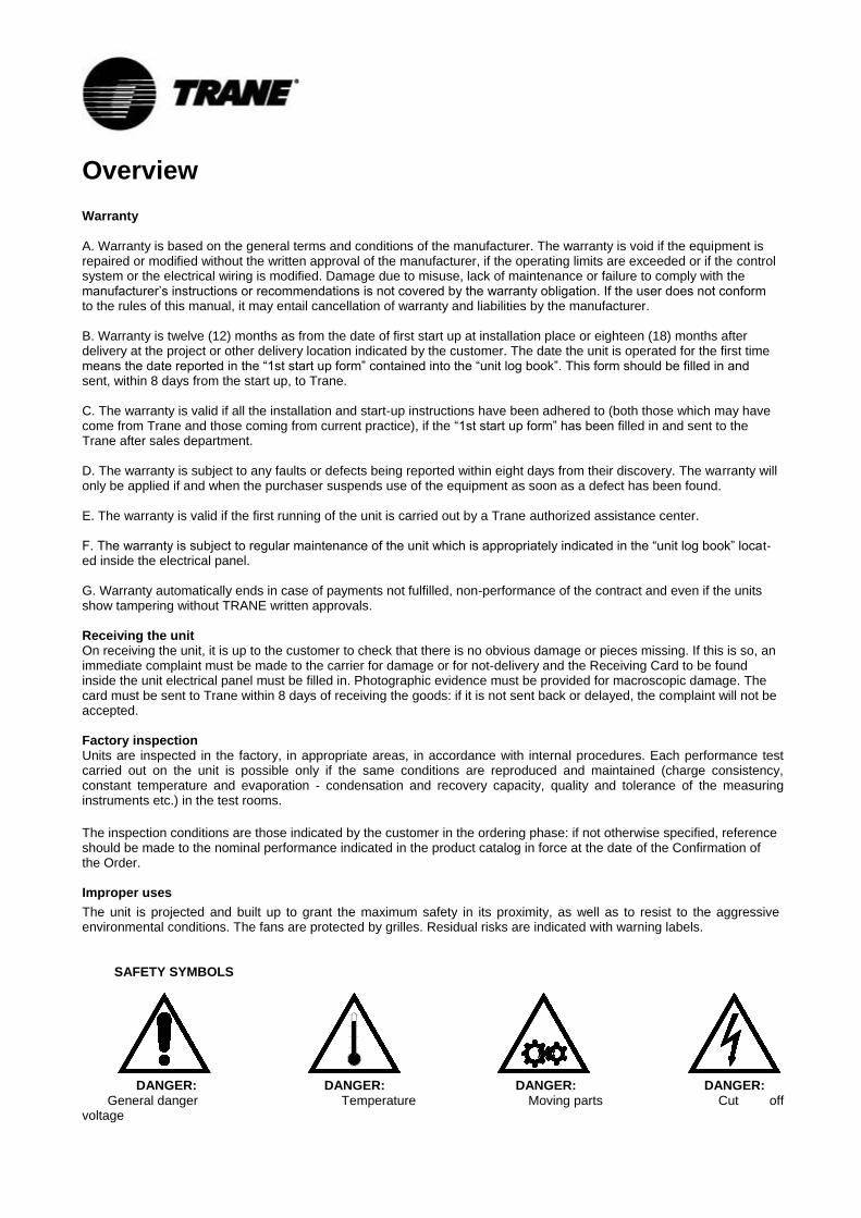
The unit is projected and built up to grant the maximum safety in its proximity, as well as to resist to the aggressive environmental conditions. The fans are protected by grilles. Residual risks are indicated with warning labels.
SAFETY SYMBOLS
DANGER: DANGER: DANGER: DANGER: General danger Temperature Moving parts Cut off voltage
Reference and certifications Reference standards
PRESSURE EQUIPMENT DIRECTIVE (97/23/EC)
UNI EN ISO 3744 ACOUSTIC REGULATION
UNI-EN-ISO 9001:2008: QUALITY MANAGEMENT SYSTEMS
LOW VOLTAGE DIRECTIVE (LVD) 2006/95/EC
MACHINERY DIRECTIVE 2006/42/EC
DIRECTIVE FOR ELECTROMAGNETIC COMPATIBILITY 2004/108/CE
CEI-EN 60204-1 DIRECTIVE (CEI44-5; CEI EN 62061) MACHINERY SAFETY – ELECTRIC MACHINERY –
EQUIPMENTS
ERP DIRECTIVE (ENERGY-RELATED-PRODUCTS ECODESIGN 2009/125/CE)
UNI EN 14511-1-2-3-4 TESTING CONDITIONS
Certifications
PED RELEASED FROM IMQ SPA - NOTIFIED BODY FOR REGULATION 97/23/EC (NO. 0051) ACCORDING TO THE
FOLLOWING STATEMENTS:
• DECLARATION OF QUALITY SYSTEM APPROVAL - FORM H1 (QUALITY ASSURANCE WITH DESIGN CONTROL
AND MONITORING OF FINAL CHECK DETAIL): CERTIFICATE N. PEC-0051-1105003.
• CERTIFICATES OF EXAMINATION OF THE PROJECT N. 0051-PEC-1105004/05/06/07/08.
QUALITY CERTIFICATION ACCORDING TO THE STANDARD UNI EN ISO 9001:2008 ISSUED BY CSQ (ACCREDIT-
ED BY ACCREDIA).
PERFORMANCE CERTIFICATION OF THE UNIT WITH THE PRESENCE OF RINA SPA DURING THE TESTING
PROCESS (OPTIONAL). GOST CERTIFICATION - (OPTIONAL) FOR PRESSURE RECIPIENTS OF THE RUSSIAN FEDERATION.
Definitions
Owner: The legal representative of the company, body or natural person who owns the plant in which the Trane unit is installed: he or she is responsible for the control and respect of all the safety regulations indicated in this manual as well as the national ones in force. Installer: The legal representative of the company appointed by the owner to position and hydraulically, electrically etc. connect the Trane unit to the plant: he or she is responsible for moving and the correct installation of the unit in accordance with the indications in this manual and with the national regulations in force. Operator: A person authorised by the owner to carry out all the operations of regulation and control on the Trane unit which are specifically mentioned in this manual. He or she should keep to actions described in the manual and limit his or her action to what is explicitly allowed. Technician: A person who is directly authorised by Trane or, secondarily, for all EU countries except for Italy, by the distributor of the Trane product, under their own responsibility, to carry out all ordinary or extraordinary maintenance operations, as well as regulations, controls, repairs and parts replacement which may be necessary during the lifetime of the unit.
Access to dangerous areas The access to the unit dangerous areas is usually obstructed through protection panels, which are removable, by using a tool. Axial fans are protected with accident prevention grilles. Finned coil, for units not equipped with coil protection grilles, is completely accessible with danger for cuts and abrasions. In these cases technicians and operators must be aware about this risk. For all the units which allow access to the cooling piping or to the packaged condensing coils with fins, without security gratings (optional) or closing panelling, the following precautions must be taken
mark the areas with contact risks.
apply warning signs The danger zone must be of a suitable size to avoid any contact, even accidental contact. In the presence of safety valves without relevant remote controls, the operating area must be of a size which considers a range of action of the discharge flow of 3 metres. Trane declines any responsibility for damage to things and unauthorised personnel in case of absence of clear and static limiting systems of the risk areas and of the relevant warning and danger signs. General precautions
The operator must only intervene on the unit controls. He or she must not open any panels except for the one which gives access to the control module. The installer must only intervene on the connections between the plant and the machine. He or she must not open any machine panels nor carry out any commands. The following precautions should be made when approaching or working on the unit: • do not wear jewellery, baggy clothes or any other accessory which can get caught up. • Use appropriate protection (gloves, glasses etc.) when using an open flame (welding) or compressed air. • If the unit is located in a closed environment, wear hearing protection. • before disconnecting, removing tubes, filters, joints or other line parts intercept the connection tubes, empty them until the pressure reaches that of the atmosphere. • do not use your hands to check for possible pressure losses. • always use tools which are in good condition; make sure the instructions have been fully understood before using them. • make sure that any tools, electrical cables or other loose objects have been removed before closing the unit and starting it up again.
Precautions against risks due to the refrigerant
Precautions against residual risks Prevention from risks due to the command system • make sure the instructions for use have been understood before carrying out any work on the control panel • always keep the instruction manual close at hand when working on the control panel • start up the unit only after having certified that it is correctly connected to the plant • inform the technician promptly of any alarms which appear on the unit • do not reset the alarms to manual restart without having first identified the cause and removed it
Prevention against residual mechanical risks • install the unit in accordance with the provisions of the following manual • carry out all the maintenance operations provided for by this manual regularly
Safety data R410a
Toxicity Not important
Risks for skin touching
Splashes or sprinkles can cause chill burns. The risk of absorptions through the skin is not relevant.
Those refrigerants could take some lightly irritating effects and in liquid stage they have a strong skinning effect. In this case it is necessary to rinse with fresh water the contaminated parts of the skin
The refrigerant in liquid stage in contact with wet clothes causes freezing and adherence to the skin. In this case it is neces-sary to take off the contaminated clothes to avoid freezing. Contact a doctor in case of irritation of the contaminated parts.
Risks for contact with the eyes
Vapors don’t take any effect. Splashes or sprinklers can cause chill burns. In those cases it is necessary to rinse eyes with water or with solution for ocular washings for 10 minutes. The intervention of a doctor is needed.
Risks for ingestion Should it happen, it causes chill burns. It does not cause vomiting. The person must be kept awake. It is needed to rinse the mouth with fresh water and to drink almost 0,25 liters. The intervention of a doctor is useful.
Risks for inhalation
High concentration of vapours in air can lead to anaesthetic effects up to a loss of conscience. Long exposures could give rise to cardiac arrhythmia and sometimes even to death.
High concentrations can create a reduction of oxygen in air, with consequent possibility of suffocation. Should it happen the person must be taken to the open air and let him to take a rest.
Administer oxygen if needed. In case the breathing has interrupted or become irregular, it is necessary to apply the artificial breathing. In case of cardiac arrest a heart massage must be applied. Contact a doctor immediately.
Conditions to avoid
Use in presence of exposed flames, and of high levels of humidity.
Dangerous reactions Possibility of violent reactions with the sodium, the potassium, the barium and with other alkaline substances, incompatible materials and all the alloys containing more than 2% of magnesium.
Protection wearing - Behav-ior in case of losses or leaks
Wear protection apparel and self respirators. Insulate the source of the loss, if this operation can be done in safety condi-tions. Small quantitative of refrigerant escaped at liquid state can be allowed to evaporate only if the room is well ventilated. In case of great losses ventilate the room immediately. Plug the loss with sand, soil or other absorbent material; avoid that the liquid refrigerant can enter in water-drainages or losing pools.
Disassembly The best procedure is the recovery and the recycle. If this is not possible the refrigerant must be conferred to an accredited system for its destruction in order to neutralize acid and toxic by-products.
• wear a protective helmet before entering inside the unit • before opening a machine panel make sure that it is firmly connected by means of a hinge • do not touch the air condensation coils without having first put on protective gloves • do not remove the protections to the moving parts while the unit is running • before restarting the unit make sure that the moving part protections are in the correct position
Prevention against residual electrical risks • connect the unit to the mains in accordance with the provisions of this manual • carry out all maintenance operations regularly • before opening the control panel disconnect the unit from the mains by means of the external knife switch • check that the unit has been earthen correctly before starting it up • control all the electrical connections, the connection cables paying particular attention to the state of isolation; replace the cables which are clearly worn or damaged • carry out periodic checks of the wiring inside the panel • do not use cables with an inappropriate section or flying connections not even for a limited period or in an emergency
Prevention against residual risks of a different nature • Residual risks due to pressure are mainly coming from non-functioning of the safety devices. To prevent them it is necessary to follow checks and replacements as following (§12.1 and 13)
• To protect from safety devices exhaust it is not allowed to remove the protections while the unit is in operation and to approach the unit without wearing the right protections. In case of accidental contact with refrigerant due to the safety valves exhaust it is necessary to follow the above (§2.5) • carry out the plant connections to the unit by following the indications reported on the following manual and on the panels of the unit itself • if a part is disassembled, make sure that it is correctly reassembled before restarting the unit • do not touch the discharge line of the compressor, the compressor itself or any other tube or component which is inside the machine without putting on protective gloves • keep a fire extinguisher which is able to put out fires on electrical equipment near the machine • on units installed inside, connect the refrigerant circuit shut off valve to a network of tubes which are able to lead the possible spillage of refrigerating fluid outside • eliminate any fluid loss inside or outside the unit • collect the discharge liquid and clean up any possible oil leakage • periodically clean the compressor casing of the accumulated dirt deposits • do not keep inflammable liquids near the unit • do not dispose of the refrigerant fluid and the lubricating oil in the environment • welding should only be carried out on empty tubes; do not approach the tubes containing refrigerant fluid with flames or other sources of heat • do not bend or strike tubes containing pressurised fluids
Precautions to be observed during maintenance operations Authorised technicians may only carry out maintenance operations. Before carrying out any maintenance the following must be performed: • isolate the unit from the mains electricity by using the external knife switch • place a notice on the external knife switch which says “do not use - maintenance in progress” • make sure that any possible on-off commands are disabled • use appropriate safety equipment (helmet, isolating gloves, protective glasses, safety shoes etc.) If measurements or controls must be carried out which require the machine to be running the following observations must be followed: • operate with the electrical panel open for as short a time as is possible • close the electrical panel as soon as the individual measurement or control has been carried out • for units which are located outside, do not carry out interventions in dangerous atmospheric conditions such as rain, snow, fog etc. The following precautions should also be taken at all times: • never dispose of fluids contained in the refrigerant circuit into the environment • when replacing an EPROM or electronic card always use appropriate equipment (extractor, anti-static bracelet, etc.) • if a compressor, the evaporator, the condensation coils or any other heavy part is to be replaced, make sure that the lifting equipment matches the weight to be lifted • in the air cooled units with an independent compressor compartment, do not open the ventilator compartment without having first isolated the machine using the knife switch on the side of the panel and only after having placed a sign which says “do not use - maintenance in progress” • if modifications must be carried out to the cooling, hydraulic or electrical circuit of the unit, as well as to its command logic, contact Trane • if particularly complicated assembly or disassembly operations are to be carried out contact Trane
• always use original spare parts bought directly from Trane or from official dealers of the companies reported in the list of recommended spare parts • if the unit is to be moved after a year of being in the site or if it has to be dismantled contact Trane
Manual alarm reset If there is an alarm the unit must not be manually reset before having located and eliminated the cause of the fault. Repeated manual resets may cause the guarantee to be void Operating range The operating ranges are indicated on the plate placed on the unit
Installation
Moving and positioning the unit The units have been designed to be lifted from above by means of eyebolts and holes in the base members. Use retractor bars to keep the lifting wires or chains away from the unit. Lifting procedures provided with the unit have to be respected.
CAUTION! Do not use forklift trucks to lift the unit from below. If equipment for lifting from above is not available, use rollers to move the unit. The surface on which the unit is placed must be flat and strong enough to withstand the weight of the unit while running. In order to reduce the transmission of vibrations to the supporting structures, fit shock absorbers in every fastening point. Rubber shock absorbers are recommended for units installed on the ground, spring shock absorbers for units installed on roofs. Open spaces around the unit must be provided for in order to allow for the passage of necessary airflow and in order to allow normal maintenance to be carried out (as shown on general catalogues). NOTE: if two units have to be installed side by side, the safety distance must be doubled. After the unit has reached the final position, fix the ant-vibration bolts. Precautions for dominant winds Avoid obstacles on suction and discharge sides of the units. Respect the safety distances as shown on the units dimensional drawings. In case of presence of dominant winds in the installation area it is strictly necessary to avoid (for units with horizontal flow fans) that such winds blow in front of the unit (fans discharge side). In case of unit with vertical flow fans it is strictly necessary to avoid installations where the dominant winds could cause rejected hot air to come back to the condensing coils. Precautions against direct sunshine Direct solar radiation can raise the temperature of condensation until it causes the unit shutdown or failure start-up of the same by action of the high pressure switch. Precautions against the presence of fireplaces and exhaust hot air Avoid installation of the machines downwind of chimneys, smokestacks and different effluent discharges. Precautions against the presence of foliage and foreign bodies Avoid installing the unit in the immediate vicinity of plants that can prevent proper intake and discharge air. Control of compressor fastening The compressors are fitted on shock absorbers. For fixing through spring ant vibration mounts, it is necessary to remove blockages put to fasten the compressors, as indicated on the label on compressors body.
Electrical connections
Electrical power supply The mains power supply characteristics have to match the unit’s absorption. The mains power supply tension must correspond to the nominal value ± 10%, with a maximum difference between the phases of 3%.
Power connections Protect the unit electric box power supply circuit with protection devices (not included in the supplied equipment) Connect the line terminals with a three-core cable of a section, which is appropriate to the machine absorption. The switch and the fuses like all the power connections must comply with the regulations in force.
Unbalance between the supply tension phases Do not run the electrical motors when the voltage unbalance between the phases is more than 3%. Use the following formula to check: % Voltage unbalance = Max voltage deviation from average * 100 Voltage average
Important! If the mains voltage has an unbalance of above 3%, contact the company which distributes the electrical energy. If the unit functions with a unit voltage unbalance between the phases of above 3% the warranty is invalid.
Evaluation of harmonic components and total harmonic distortion THD value The bridge rectifier of an inverter requires from the mains a current that is not purely sinusoidal. In fact, due to the pres-ence of the diodes (non-linear components), the current absorbed by a bridge rectifier presents frequency components higher than the mains frequency. These components are called harmonics; in case of power supply at 50 Hz is called the fundamental harmonic component at 50 Hz, the second harmonic is the component to 100 Hz, the third harmonic is the component at 150 Hz and so on (in the case of power 60Hz to the fundamental component is at 60Hz, the second har-monic is 120Hz, 180Hz in the third and so on).
Since the bridge rectifier sees in front of him one stage direct current, the current drawn is practically, in phase with the voltage. However it is no longer true the relationship between the classical electrical quantities: because the higher harmonics to the fundamental components do not contribute to the active power. We must therefore define different sizes:
Displacement Power Factor (power factor lag)
Power Factor (total power factor)
The Power Factor takes into account both the phase shift that the harmonic content, expressed as the ratio between the fundamental component of the current I1, and the overall RMS value. It expresses how much of braids of the input cur-rent is converted into active power. It is worth noting that, in the absence of inverters or devices electronics in general, DPF and PF are the same. Moreover, the majority of entities in the electric energy distribution take account only of the DPF, as the harmonic content is not measured, but only the absorption of active and reactive energy.
Another index of measurement of harmonics fed into the grid is given by THDi THD (Total Harmonic Distortion) so de-fined:
In an inverter without expedients harmonic distortion can reach values higher than 100% (i.e. the components
Harmonics can, on the whole have a width greater than the fundamental component). In order to reduce the harmonic content of the current (and therefore the THD) units object of this manual are equipped with appropriate limitation sys-tems. Since the harmonic content depends on the ratio between the current required by the inverter and the short-circuit current at the point of connection, the THD for a given plant varies depending on the absorption of the machine.
It should also be said that the harmonic distortion is reduced in value if the connection point (CCP) are also connected
other loads: the greater the weight of these utilities, the lower the current distortion. The total harmonic distortion at the point where the unit is connected to the network is a function of the ratio between short-circuit current circuit at the point of connection (ISC) and the current drawn by the unit (IL) and the percentage of power drawn the unit compared to the total power supplied by the network at the connection point. The harmonic distortion in the connection point can 'assume values very low (less than 5%) if the short circuit current is less than 20 times the current of unity and this constitutes a percentage not more than 20% of the total load of the network. In any case, the harmonic distortion introduced by the unit must be determined by reference to the specific application after a detailed analysis of the entire network of power and loads supplied.
Water connections for air-water
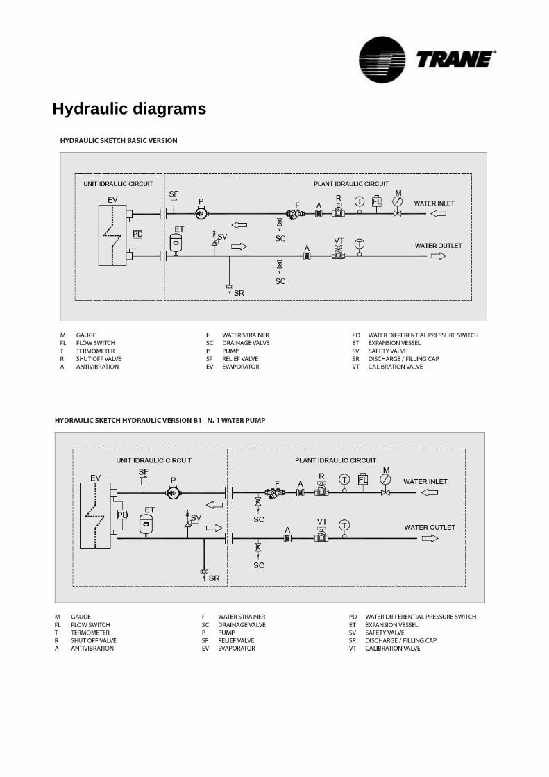
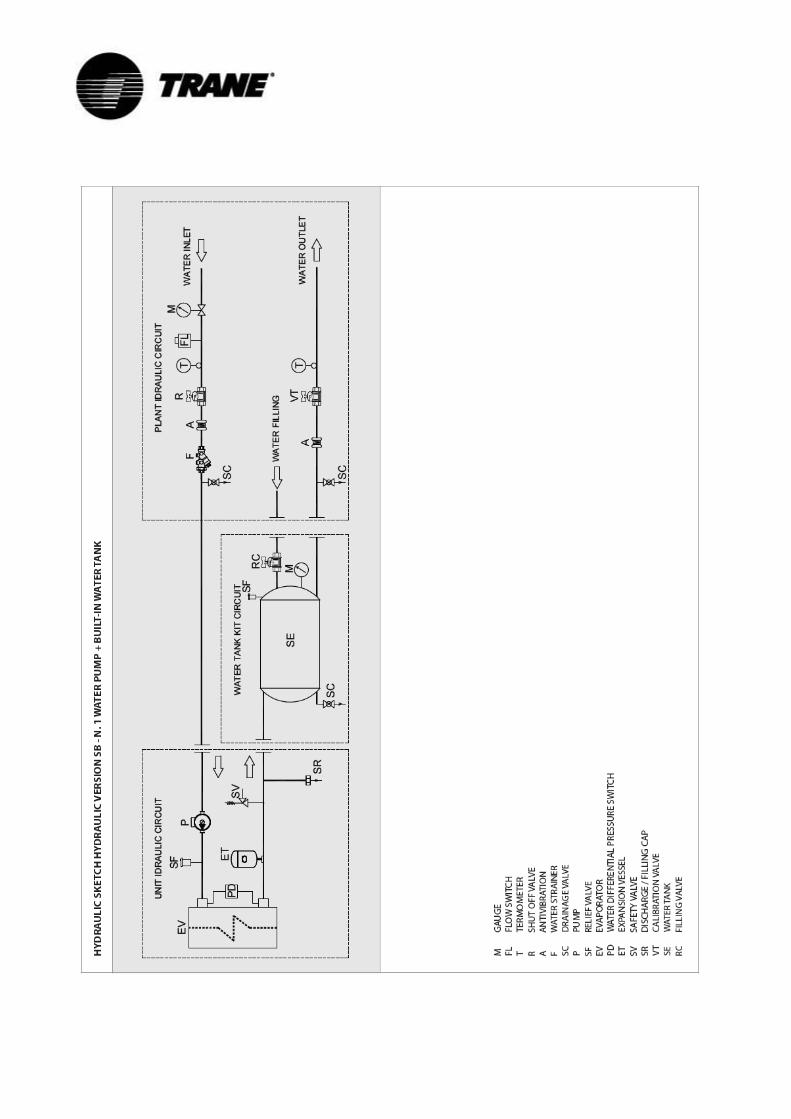
Evaporator The connection tubes have to be supported in order that their weight does not damage the plant. The following parts have to be installed on the water circuit of the evaporator: 1. Two pressure gauges of adequate scale (in and out of the unit) 2. Two shock-absorbing joints (inlet and out of the unit) 3. One shut off valve (normal one inlet) 4. One setting valve (in outlet) 5. Two thermometers (inlet and outlet) 6. One circulation pump 7. One safety valve on the water buffer (if not equipped in the unit) 8. One automatic air vent valve (if not equipped in the unit) 9. One expansion vessel (if not equipped in the unit and one in addition depending on the volume of water in the
plant) 10. An inlet filter placed as near as possible to the evaporator connection. 11. One flow switch
The above-mentioned installation indications represent necessary conditions for the guarantee to be valid. Trane is at your disposal to examine any different requirements, which have to be approved before starting up the chiller. It is necessary that the water flow rate to the unit is compatible with the evaporator one. It is also necessary that the water flow rate is kept uniform while the unit is running: it is suggested to use always a pump system dedicated to the unit and independent from the remaining part of the plant. Before storing units in temperatures around 0°C evacuate the exchanger with compressed air in order to avoid breakages due to ice. Condenser Condenser piping must follow the same installation procedures as for the evaporator. Condensing temperature and water flow rate have to be in accordance with nominal values, unless the acknowledgement order shows different indications. It is necessary that in the presence of condenser side dirty or aggressive water, an intermediate heat exchanger must be installed before the chiller condenser. The above-mentioned installation suggestions represent the necessary condition to keep warranty validity. Calculation of minimum water content and flow rates To achieve perfect operation, the machine needs water content achievable using the following formula: CHILLER: OPTIMAL V= Qev/20 MINIMUM V= Qev/35 HEAT PUMP OPTIMAL V= Qcond/7 MINIMUM V= Qcond/20
Qev = EVAPORATOR FLOW RATE Qcond = CONDENSER FLOW RATE V = WATER VOLUME in cubic meters The permitted tolerance for flow rates is equal to 10% of the nominal provided in product catalog. Water circuit regulation equipment
Centrifugal motor water pump: Assures the discharge and the prevalence necessary to supply tube nest evaporator, the tank and the utility.
Automatic filling unit: Assures the water pressure in the plant is maintained at least 1.5 bar, automatically resetting it when necessary.
Safety valve: Takes care of opening the unit in atmosphere if the pressure exceeds the calibration value.
Expansion tank (if not equipped in the unit and one in addition depending on the volume of water in the plant): Takes care of compensating small water hammering and variations of volume for different temperatures.
Check valves: Take care of intercepting the pump for possible maintenance.
Hydraulic diagrams

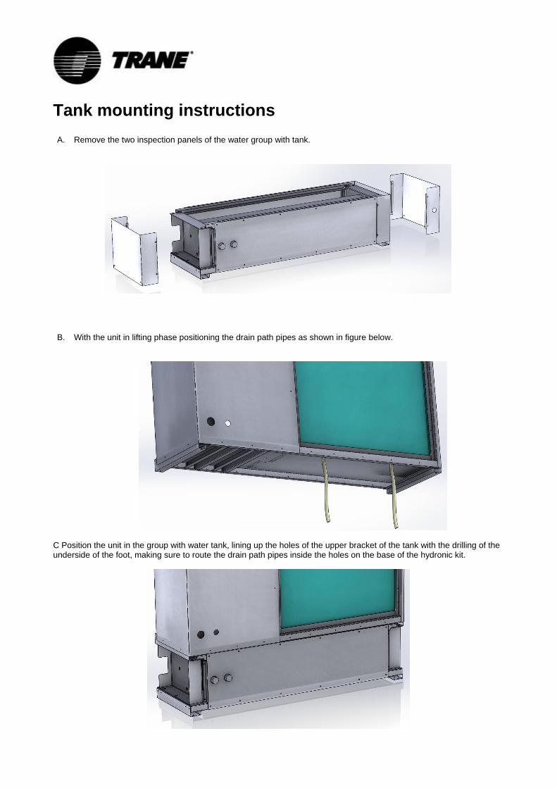
Tank mounting instructions A. Remove the two inspection panels of the water group with tank.
B. With the unit in lifting phase positioning the drain path pipes as shown in figure below.
C Position the unit in the group with water tank, lining up the holes of the upper bracket of the tank with the drilling of the underside of the foot, making sure to route the drain path pipes inside the holes on the base of the hydronic kit.
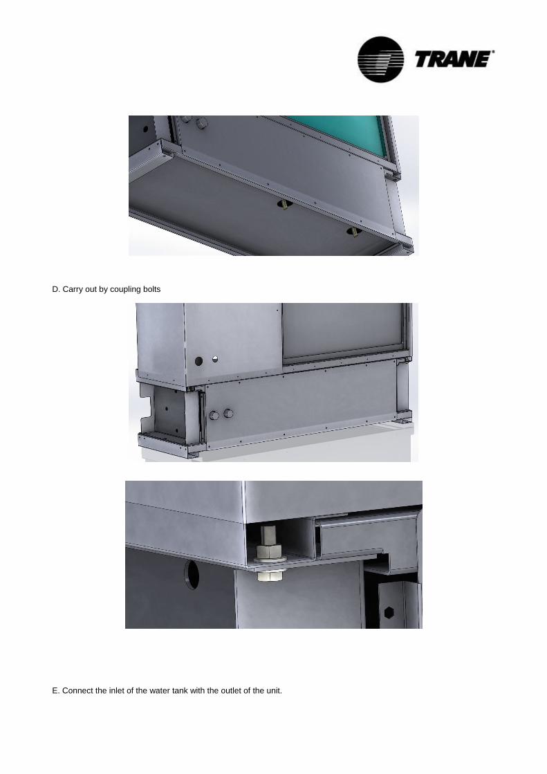
D. Carry out by coupling bolts
E. Connect the inlet of the water tank with the outlet of the unit.
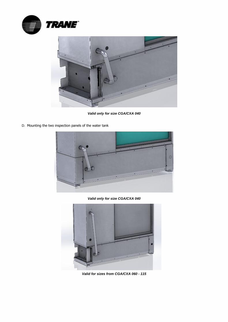
Valid only for size CGA/CXA 040
D. Mounting the two inspection panels of the water tank
Valid only for size CGA/CXA 040
Valid for sizes from CGA/CXA 060 - 115
Start-up procedures
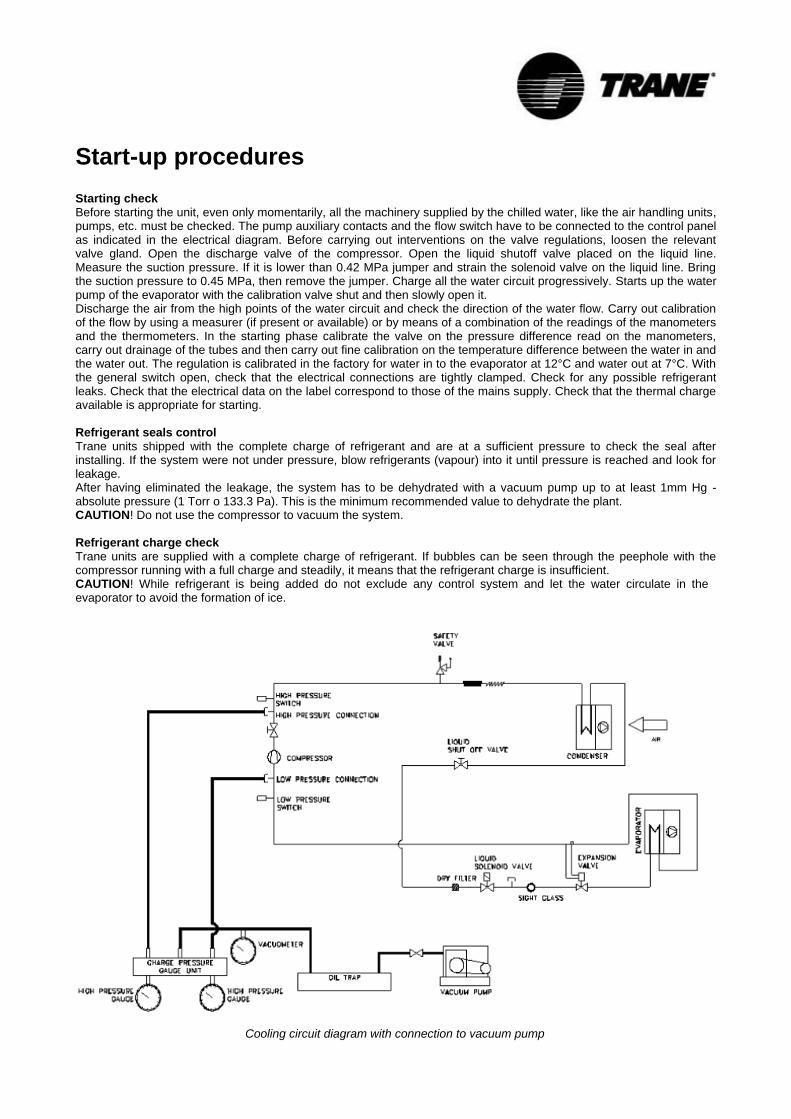
Starting check Before starting the unit, even only momentarily, all the machinery supplied by the chilled water, like the air handling units, pumps, etc. must be checked. The pump auxiliary contacts and the flow switch have to be connected to the control panel as indicated in the electrical diagram. Before carrying out interventions on the valve regulations, loosen the relevant valve gland. Open the discharge valve of the compressor. Open the liquid shutoff valve placed on the liquid line. Measure the suction pressure. If it is lower than 0.42 MPa jumper and strain the solenoid valve on the liquid line. Bring the suction pressure to 0.45 MPa, then remove the jumper. Charge all the water circuit progressively. Starts up the water pump of the evaporator with the calibration valve shut and then slowly open it. Discharge the air from the high points of the water circuit and check the direction of the water flow. Carry out calibration of the flow by using a measurer (if present or available) or by means of a combination of the readings of the manometers and the thermometers. In the starting phase calibrate the valve on the pressure difference read on the manometers, carry out drainage of the tubes and then carry out fine calibration on the temperature difference between the water in and the water out. The regulation is calibrated in the factory for water in to the evaporator at 12°C and water out at 7°C. With the general switch open, check that the electrical connections are tightly clamped. Check for any possible refrigerant leaks. Check that the electrical data on the label correspond to those of the mains supply. Check that the thermal charge available is appropriate for starting.
Refrigerant seals control Trane units shipped with the complete charge of refrigerant and are at a sufficient pressure to check the seal after installing. If the system were not under pressure, blow refrigerants (vapour) into it until pressure is reached and look for leakage. After having eliminated the leakage, the system has to be dehydrated with a vacuum pump up to at least 1mm Hg - absolute pressure (1 Torr o 133.3 Pa). This is the minimum recommended value to dehydrate the plant. CAUTION! Do not use the compressor to vacuum the system.
Refrigerant charge check Trane units are supplied with a complete charge of refrigerant. If bubbles can be seen through the peephole with the compressor running with a full charge and steadily, it means that the refrigerant charge is insufficient. CAUTION! While refrigerant is being added do not exclude any control system and let the water circulate in the evaporator to avoid the formation of ice.
Cooling circuit diagram with connection to vacuum pump
Refrigerant charge
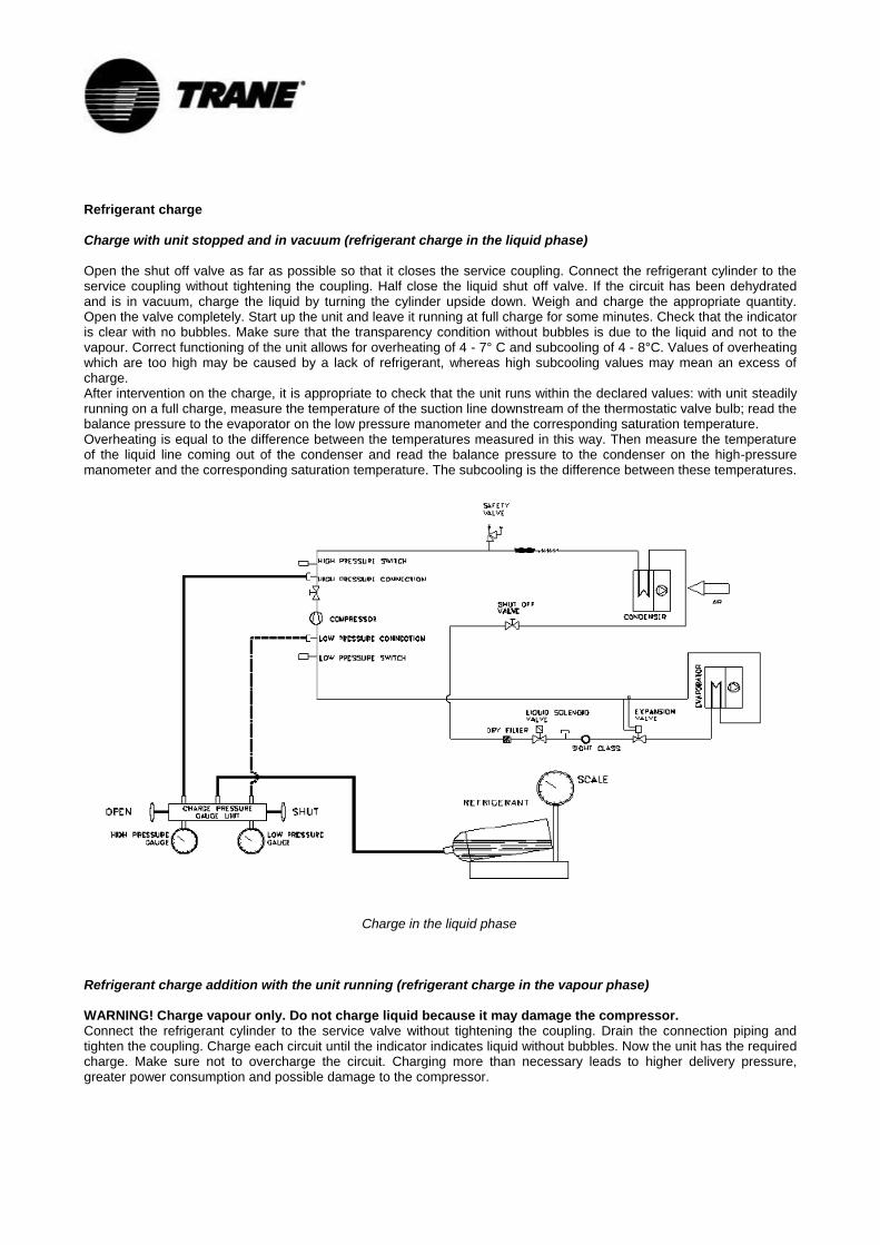
Charge with unit stopped and in vacuum (refrigerant charge in the liquid phase)
Open the shut off valve as far as possible so that it closes the service coupling. Connect the refrigerant cylinder to the service coupling without tightening the coupling. Half close the liquid shut off valve. If the circuit has been dehydrated and is in vacuum, charge the liquid by turning the cylinder upside down. Weigh and charge the appropriate quantity. Open the valve completely. Start up the unit and leave it running at full charge for some minutes. Check that the indicator is clear with no bubbles. Make sure that the transparency condition without bubbles is due to the liquid and not to the vapour. Correct functioning of the unit allows for overheating of 4 - 7° C and subcooling of 4 - 8°C. Values of overheating which are too high may be caused by a lack of refrigerant, whereas high subcooling values may mean an excess of charge. After intervention on the charge, it is appropriate to check that the unit runs within the declared values: with unit steadily running on a full charge, measure the temperature of the suction line downstream of the thermostatic valve bulb; read the balance pressure to the evaporator on the low pressure manometer and the corresponding saturation temperature. Overheating is equal to the difference between the temperatures measured in this way. Then measure the temperature of the liquid line coming out of the condenser and read the balance pressure to the condenser on the high-pressure manometer and the corresponding saturation temperature. The subcooling is the difference between these temperatures.
Charge in the liquid phase
Refrigerant charge addition with the unit running (refrigerant charge in the vapour phase)
WARNING! Charge vapour only. Do not charge liquid because it may damage the compressor. Connect the refrigerant cylinder to the service valve without tightening the coupling. Drain the connection piping and tighten the coupling. Charge each circuit until the indicator indicates liquid without bubbles. Now the unit has the required charge. Make sure not to overcharge the circuit. Charging more than necessary leads to higher delivery pressure, greater power consumption and possible damage to the compressor.
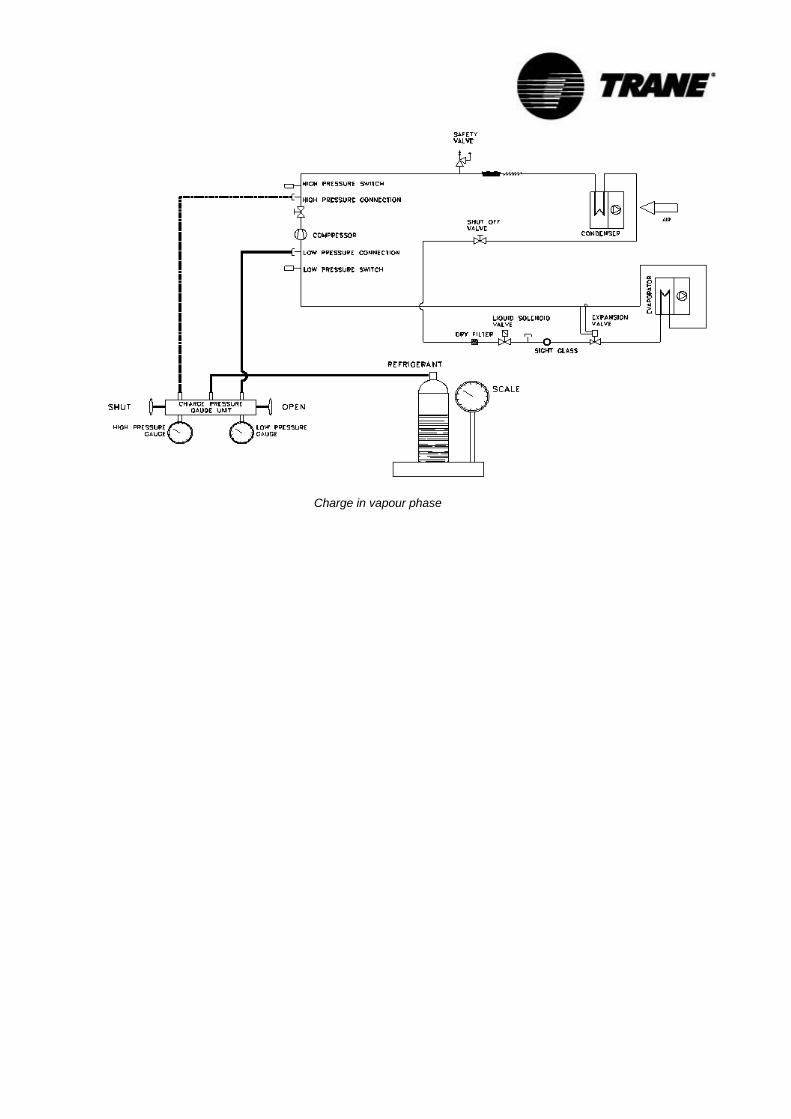
Charge in vapour phase
Start-up
Preliminary controls Before starting up the equipment it is very important to check that all the operations described in the paragraph “SETTING FOR START UP” have been carried out correctly. Moreover check that all the mechanical and electric equipment has been tightened perfectly. Particular attention should be paid to the main components (compressor, exchangers, ventilators, electrical motors, and pump) if loose fastenings are found tighten them well before starting up the machine. The oil heaters have to be inserted at least 8 hours before starting up. Ensure that the compressors’ carter is hot. Open the compressor valve and the cooling circuit one, which may have been shut for charging. Control all the machinery connected to the unit.
Starting up Start up the unit by pressing the ON/OFF button. About 20 seconds pass from the moment in which the start up request of the unit is given to the moment in which the (first) compressor starts. Three hundred and sixty seconds will pass from the last shut down to the next start-up of the same compressor. Check the rotation direction of the fans and rotary compressors. If it is not the right one, invert two supply phases. Ensure that all the safety and control equipment is functioning correctly. Control the temperature of the water coming out of the evaporator and regulate the control setting if necessary. Control the oil level. Warm up of the plant for air-to-water units In order to keep all the machine components in good condition and to optimise their use, during the warm up it is necessary to bring the circuit to the right temperature before releasing cooling energy to the utilities. The following steps must be followed for this to be carried out:
start up the machine
wait for the water in temperature to reach the running temperature
start up the consumers Follow the above mentioned procedure every time the plant is stopped long enough for the water temperature contained in it to rise.
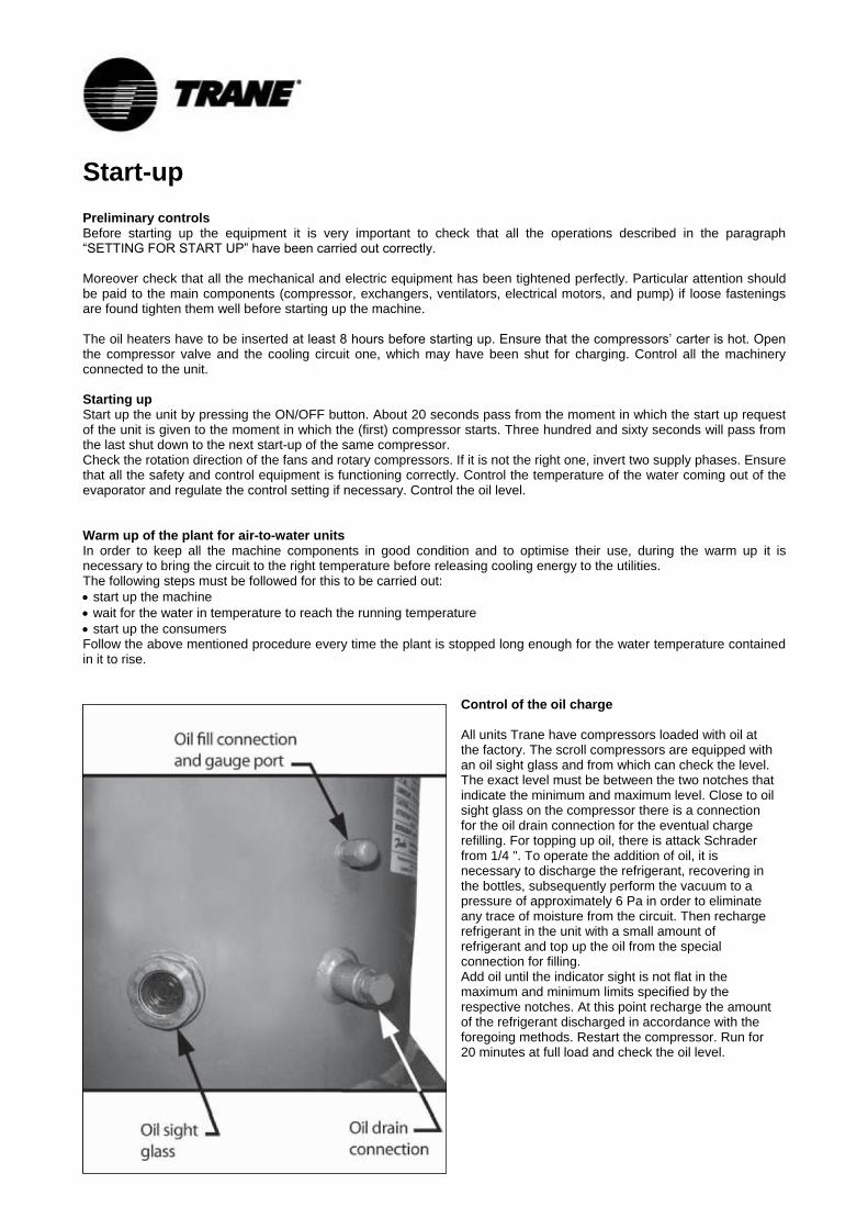
Control of the oil charge All units Trane have compressors loaded with oil at the factory. The scroll compressors are equipped with an oil sight glass and from which can check the level. The exact level must be between the two notches that indicate the minimum and maximum level. Close to oil sight glass on the compressor there is a connection for the oil drain connection for the eventual charge refilling. For topping up oil, there is attack Schrader from 1/4 ". To operate the addition of oil, it is necessary to discharge the refrigerant, recovering in the bottles, subsequently perform the vacuum to a pressure of approximately 6 Pa in order to eliminate any trace of moisture from the circuit. Then recharge refrigerant in the unit with a small amount of refrigerant and top up the oil from the special connection for filling. Add oil until the indicator sight is not flat in the maximum and minimum limits specified by the respective notches. At this point recharge the amount of the refrigerant discharged in accordance with the foregoing methods. Restart the compressor. Run for 20 minutes at full load and check the oil level.
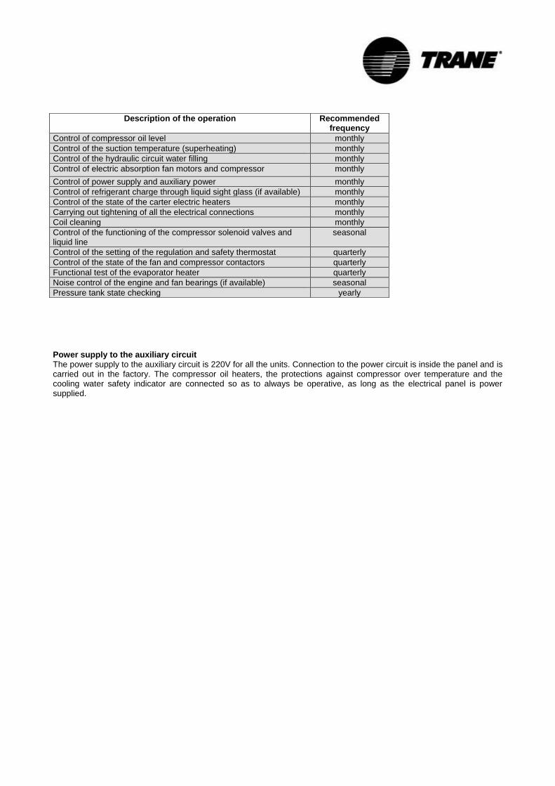
Power supply to the auxiliary circuit The power supply to the auxiliary circuit is 220V for all the units. Connection to the power circuit is inside the panel and is carried out in the factory. The compressor oil heaters, the protections against compressor over temperature and the cooling water safety indicator are connected so as to always be operative, as long as the electrical panel is power supplied.
Description of the operation Recommended frequency
Control of compressor oil level monthly
Control of the suction temperature (superheating) monthly
Control of the hydraulic circuit water filling monthly
Control of electric absorption fan motors and compressor monthly
Control of power supply and auxiliary power monthly
Control of refrigerant charge through liquid sight glass (if available) monthly
Control of the state of the carter electric heaters monthly
Carrying out tightening of all the electrical connections monthly
Coil cleaning monthly
Control of the functioning of the compressor solenoid valves and liquid line
seasonal
Control of the setting of the regulation and safety thermostat quarterly
Control of the state of the fan and compressor contactors quarterly
Functional test of the evaporator heater quarterly
Noise control of the engine and fan bearings (if available) seasonal
Pressure tank state checking yearly
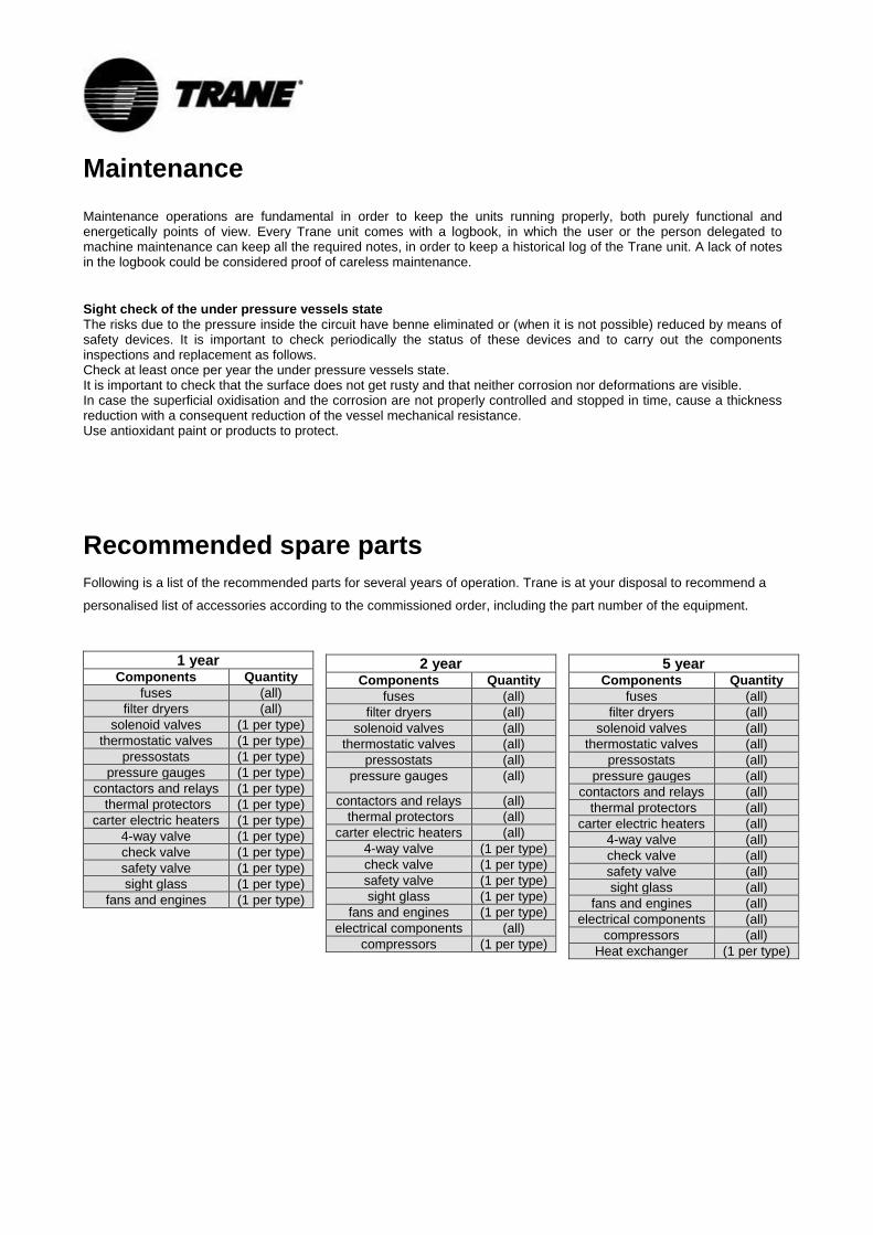
Maintenance
Maintenance operations are fundamental in order to keep the units running properly, both purely functional and energetically points of view. Every Trane unit comes with a logbook, in which the user or the person delegated to machine maintenance can keep all the required notes, in order to keep a historical log of the Trane unit. A lack of notes in the logbook could be considered proof of careless maintenance.
Sight check of the under pressure vessels state The risks due to the pressure inside the circuit have benne eliminated or (when it is not possible) reduced by means of safety devices. It is important to check periodically the status of these devices and to carry out the components inspections and replacement as follows. Check at least once per year the under pressure vessels state. It is important to check that the surface does not get rusty and that neither corrosion nor deformations are visible. In case the superficial oxidisation and the corrosion are not properly controlled and stopped in time, cause a thickness reduction with a consequent reduction of the vessel mechanical resistance. Use antioxidant paint or products to protect.
Recommended spare parts
Following is a list of the recommended parts for several years of operation. Trane is at your disposal to recommend a
personalised list of accessories according to the commissioned order, including the part number of the equipment.
1 year Components Quantity
fuses (all)
filter dryers (all)
solenoid valves (1 per type)
thermostatic valves (1 per type)
pressostats (1 per type)
pressure gauges (1 per type)
contactors and relays (1 per type)
thermal protectors (1 per type)
carter electric heaters (1 per type)
4-way valve (1 per type)
check valve (1 per type)
safety valve (1 per type)
sight glass (1 per type)
fans and engines (1 per type)
2 year Components Quantity
fuses (all)
filter dryers (all)
solenoid valves (all)
thermostatic valves (all)
pressostats (all)
pressure gauges (all)
contactors and relays (all)
thermal protectors (all)
carter electric heaters (all)
4-way valve (1 per type)
check valve (1 per type)
safety valve (1 per type)
sight glass (1 per type)
fans and engines (1 per type)
electrical components (all)
compressors (1 per type)
5 year Components Quantity
fuses (all)
filter dryers (all)
solenoid valves (all)
thermostatic valves (all)
pressostats (all)
pressure gauges (all)
contactors and relays (all)
thermal protectors (all)
carter electric heaters (all)
4-way valve (all)
check valve (all)
safety valve (all)
sight glass (all)
fans and engines (all)
electrical components (all)
compressors (all)
Heat exchanger (1 per type)
Trane optimizes the performance of homes and buildings around the world. A business of Ingersoll Rand, the leader in creating and sustaining safe, comfortable and energy efficient environments, Trane offers a broad portfolio of ad-vanced controls and HVAC systems, comprehensive building services, and parts. For more information, visit www.Trane.com. Trane has a policy of continuous product and product data improvement and reserves the right to change design and specifications without notice. © 2015 Trane All rights reserved CG-SVX031A-GB May 2015