installation, operation & maintenance - lewco, inc operation & maintenance ... alert...
TRANSCRIPT

Installation, Operation & Maintenance Manual
Model MDSWM Medium Duty Slider Bed Flat Wire Mesh
Effective: July, 2012
Rev: 01 Copyright© 2012 LEWCO, Inc
www.lewcoinc.com An ISO 9001:2008 Registered Company
LEWCO, Inc. 706 Lane Street Sandusky, Ohio 44870 Phone 419.625.4014 Fax 419.625.1247 www.lewcoinc.com
Installation, Operation & Maintenance
Page 2 Copyright® 2006 LEWCO, Inc.
Warranty
NOTE: This warranty supersedes all previous editions.
Seller’s warranty as stated herein shall be effective only upon payment in full by the Buyer for the affected goods and/or services. Every LEWCO, Inc. product has been carefully inspected before shipment and we guarantee to correct any defect caused by faulty material or workmanship. Seller's obligation under this warranty is for one year or 4000 hours of use, whichever comes first, after shipment of products or equipment. The Seller warrants that the equipment furnished and the material used in its manufacturing shall be of good quality and free from defects. Subject to the conditions stated herein, the Seller will replace (F.O.B. Sandusky, OH) or repair any equipment proving defective in material or workmanship. Defect(s) to be verified by Seller's inspection upon receiving products or equipment at Seller's plant. Cost for shipping of defective and/or replacement parts to be incurred by Buyer. Credit for return shipping charges may be issued to the Buyer after any and all inspections are concluded. Failure due to abuse, overloading, maintenance neglect, exposure to corrosive or abrasive materials, or improper use shall not be subject to said warranty. Any modification to equipment or systems without Seller’s written consent voids this warranty. Component parts not of Seller's manufacture (such as motors, fans and reducers) will be covered by the original manufacturer's warranty and not by Seller. In the case of failure during the warranty period, contact your Seller’s representative or the nearest authorized service representative of the manufacturer. Standard warranty does not include labor to remove and/or install defective equipment. If a Seller’s Representative is required for additional assistance, contact our Customer Service Department. Labor will be charged at a prevailing rate, plus travel expenses. Seller shall not be liable for loss of profits, delays or expenses incurred by failure of said parts, whether incidental or consequential. Except as stated herein, the Seller makes no other warranties, expressed or implied, including warranties of merchantability and fitness for a particular purpose. There are no warranties, which extend beyond the description on the face thereof. Buyer's exclusive remedy for claims arising hereunder shall be for damages. The Seller's alleged liability for defective products or equipment, irrespective of whether such defects are discoverable or latent, shall in no event exceed the cost to the Seller of repairing, at the Seller's option, the defective or damaged products or equipment. In no event, including in the cost of a claim of negligence, shall the Seller be liable for incidental or consequential damage. The Seller makes no warranties or representations, express or implied, with respect to the product or any service, advice or consultation, if any, furnished to the Buyer by any other party, by the Seller or its representatives. Seller shall not be liable for any loss, personal injury or property damage directly or indirectly arising from the use of its product, advice or service, or for incidental, consequential or punitive damages of any description, whether any such claim be based on warranty, contract, negligence, strict liability or other tort, or otherwise. No deviation from these standard Terms and Conditions of Warranty will be recognized or allowed unless prior written authorization is obtained by Buyer, from Seller.

Installation, Operation & Maintenance
Page 3 Copyright® 2006 LEWCO, Inc.
Contents
Warranty……………………………………………………………………………………………………………………….2 Safety .........................................................................................................................................................................4 Hazard Labels ...........................................................................................................................................................4 Safety Considerations ..............................................................................................................................................4
Guards and Guarding .............................................................................................................................................4 Operation & Use .....................................................................................................................................................5 Maintenance & Troubleshooting ............................................................................................................................6 Before Re-Starting the Conveyor ...........................................................................................................................6
Support Installation ..................................................................................................................................................6 Conveyor Set Up .......................................................................................................................................................7 Belt Alignment and Tracking Procedure ................................................................................................................7 Pre-Startup Checks ............................................................................................................................................... 10 Maintenance ........................................................................................................................................................... 11
Maintenance Intervals ......................................................................................................................................... 11 Maintenance Procedures .................................................................................................................................... 12 Sprocket and Chain Maintenance ....................................................................................................................... 12 Belt ...................................................................................................................................................................... 12 Motor and Reducer .............................................................................................................................................. 12 Rollers and Bearings ........................................................................................................................................... 12 Conveyor Bed and Supports ............................................................................................................................... 12 Cleaning .............................................................................................................................................................. 12
Troubleshooting .................................................................................................................................................... 13 Replacement Parts ................................................................................................................................................ 14 How to Order .......................................................................................................................................................... 14

Installation, Operation & Maintenance
Page 4 Copyright® 2006 LEWCO, Inc.
Safety
Hazard Labels
To reduce the possibility of injury to personnel operating or in the vicinity of LEWCO conveying
equipment, warning signs are posted at potential hazard points on the equipment. Examine this
equipment and become familiar with potential hazard areas.
Instruct all personnel to heed these potential hazard areas.
The following illustrations represent the typical hazard signs found at hazardous areas on LEWCO
Conveyors.
Safety Considerations
Guards and Guarding
All LEWCO standard conveyor equipment is equipped with standard machine guarding methods. It is the responsibility of the owner, however, to ensure that proper guarding methods are present to comply with OSHA
Installation, Operation & Maintenance
Page 5 Copyright® 2006 LEWCO, Inc.
Standards – 29 CFR – 1910.212 Machinery and Machine Guarding. Special consideration should be given to areas where multiple pieces of equipment interface.
1910.212(a)
Machine guarding.
1910.212(a)(1)
Types of guarding. One or more methods of machine guarding shall be provided to protect the operator and other employees in the machine area from hazards such as those created by point of operation, ingoing nip points, rotating parts, flying chips and sparks. Examples of guarding methods are barrier guards, two-hand tripping devices, electronic safety devices, etc.
1910.212(a)(2)
General requirements for machine guards. Guards shall be affixed to the machine where possible and secured elsewhere if for any reason attachment to the machine is not possible. The guard shall be such that it does not offer an accident hazard in itself.
1910.212(a)(3)
Point of operation guarding.
1910.212(a)(3)(i)
Point of operation is the area on a machine where work is actually performed upon the material being processed.
1910.212(a)(3)(ii)
The point of operation of machines whose operation exposes an employee to injury, shall be guarded. The guarding device shall be in conformity with any appropriate standards thereof, or, in the absence of applicable specific standards, shall be so designed and constructed as to prevent the operator from having any part of his body in the danger zone during the operating cycle.
1910.212(a)(3)(iii)
Special hand tools for placing and removing material shall be such as to permit easy handling of material without the operator placing a hand in the danger zone. Such tools shall not be in lieu of other guarding required by this section, but can only be used to supplement protection provided.
Operation & Use
Only experienced and trained personnel should operate the conveyor.
Personnel should be trained in operation under normal and emergency conditions.
Personnel on or near the conveyor should be instructed as to the location and operation of stopping
devices.
Keep starting and stopping controls free from obstructions, and instruct personnel working at or near the
conveyor of their locations.
Do not wear loose clothing while operating the conveyor. Long hair and jewelry are potential hazards of
entanglement.
Watch for hazardous conditions—sharp edges and protruding parts, etc.
Use the conveyor to transport only material it is capable of being handled safely.
Keep area around loading and unloading points free from obstructions.
Prohibit personnel from riding on the conveyor.
Before turning the conveyor ON, inspect it for foreign objects that could injure personnel or damage the
equipment.
Alert personnel in the area prior to starting conveyor.
Check belt tracking to make sure it is running straight on the conveyor.
Installation, Operation & Maintenance
Page 6 Copyright® 2006 LEWCO, Inc.
After startup, make sure all areas of the conveyor are operating properly.
Maintenance & Troubleshooting
Only experienced and trained personnel should perform maintenance, including lubrication and
adjustments.
A maintenance program should be established to insure that all conveyor components are maintained in
a condition which does not constitute a hazard to personnel.
Turn OFF and lockout the main power switches to the conveyor, following lockout/tagout procedures.
Do not perform any work on the conveyor while it is running unless the nature of the maintenance
absolutely requires operation of the conveyor. If the conveyor must be operated to perform maintenance
procedures, allow only experienced conveyor maintenance personnel to do the work.
Do not wear loose clothing while performing maintenance on an operating conveyor.
Use extreme care when using mechanical aids such as hoists, cables, and other equipment to perform
maintenance. They can cause damage to the conveyor and cause a dangerous condition when the
conveyor is turned on.
Poor housekeeping practices cause accidents and inefficient conveyor operation. Keep area and
conveyor clean from spilled lubricants and other materials. Make sure no material is caught or lodged in
the movable parts of the conveyor unless necessary during maintenance.
Before Re-Starting the Conveyor
Inspect the conveyor and make certain all safety devices and guards are in place.
Make sure all tools and/or maintenance equipment have been removed from the conveyor area.
Make sure no material is caught or lodged in the movable parts of the conveyor.
Make sure all personnel are clear of the conveyor and are alerted that the conveyor is about to be started.
Allow only authorized personnel to start the conveyor following maintenance or any emergency shut-off.
Support Installation
Bolts for attaching the supports to the
bed sections are shipped in a bag
attached to the supports or in a
separate box.
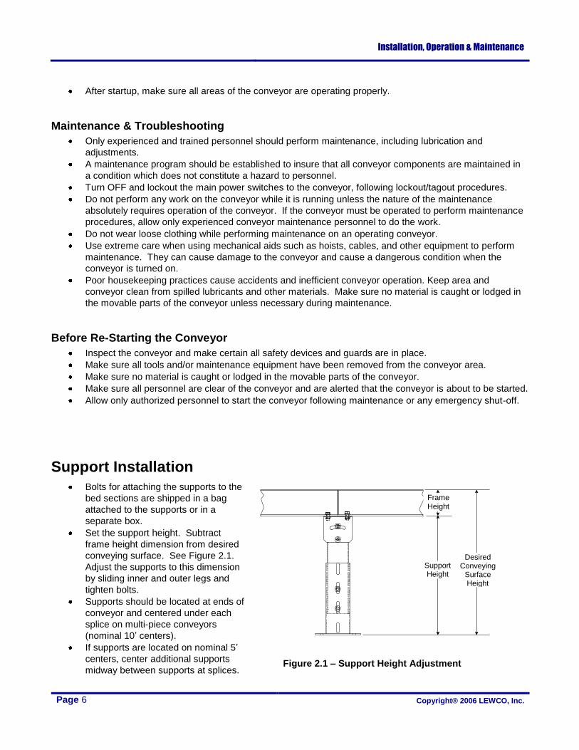
Set the support height. Subtract
frame height dimension from desired
conveying surface. See Figure 2.1.
Adjust the supports to this dimension
by sliding inner and outer legs and
tighten bolts.
Supports should be located at ends of
conveyor and centered under each
splice on multi-piece conveyors
(nominal 10’ centers).
If supports are located on nominal 5’
centers, center additional supports
midway between supports at splices. Figure 2.1 – Support Height Adjustment
Frame Height
Support Height
Desired Conveying
Surface Height

Installation, Operation & Maintenance
Page 7 Copyright® 2006 LEWCO, Inc.
Conveyor Set Up
Mark a chalk line on floor to locate center of the conveyor.
Place the drive section in position.
Install remaining sections in order. Conveyor sections have a section number label, which includes the
Sales Order number, Line Item number, and Section Assembly number (last two digits). Conveyors made
up of more than one section are to be assembled in ascending numerical order, starting with Section
Assembly 01 at the product infeed end.
Check that conveyor is level across both width and length of conveyor. Adjust supports if necessary.
Check all bed sections for square. See Figure 3.1. Use a string stretched from opposing corners at edge
of bed to aid in straightening conveyor. Ensure that both dimensions are the same. Adjust or shim
supports as required. Both sides of the conveyor must be in the same plane (bed not twisted).
Tighten all butt couplings and support
mounting bolts and lag conveyor to floor.
Install and track belt.
Belt Alignment and Tracking Procedure
Since the majority of belting problems are alignment related, it is extremely important to have a properly aligned conveyor system. Improperly aligned systems will result in excessive wear and edge damage. Misaligned systems can also lead to premature wearing of the sprockets and have been known to cause damage to the product being conveyed.
If a good alignment is not completed before using a flat wire belt, longitudinal pitch can be permanently distorted causing the belt to track to one side. Improper handling of the belt before and during installation can also damage the belt so as to create alignment problems. Properly aligning a conveyor system prior to running the belt, along with periodic inspections will lead to a longer belt life.
A rule of thumb to follow is the belt will move to the side of the conveyor it contacts first. • If a belt is running over rollers and one is skewed, the belt will track to whichever
side is skewed toward the tail end of the conveyor. • If the conveyor bed is not level, the belt will track to the higher side. • If there is a build-up of material between the bed and the belt on one side, the belt
will track to that side.
A second rule of thumb is that the belt will run in a direction perpendicular to the roll over which it passes. Lewco Inc. also recommends that the total belt length to width ratio be no less than 5:1 as tracking problems are more likely to occur with wide belts which have a short length.
Figure 3.1 Check the bed for square

Installation, Operation & Maintenance
Page 8 Copyright® 2006 LEWCO, Inc.
Aligning a System
1. Align the head and tail shafts (or rolls) so that they are level, perpendicular to the direction of belt travel, and parallel to each other. Check the parallelism of the shafts by comparing the distance between the centers of the shafts in a straight line and on the diagonal. The straight line distance on the left side should equal the straight line distance on the right side, as should the diagonal distances from left to right and from right to left. After these shafts have been aligned, they should be fixed and pinned in place. Never use the head or tail shafts to track the belt.
2. Next adjust the conveyor bed or rolls so that
they are level and parallel to the drive and tail shafts. This should be done on both the loaded side and the return side of the conveyor. Conveyor rolls should be level to ±1/32”. All rollers should be flat faced.
3. Inspect the rolls for debris, excessive wear, and roundness. All rolls should turn freely and should be neither bent nor bowed.
4. Any surfaces over which the belt will travel should be checked for sharp edges or obstructions. Any edges should be filed smooth. These surfaces should also be level and parallel to each other and the direction of belt travel.
5. Lewco Inc. does not recommend the use of alignment guides contacting the edges of a flat wire belt, as they can cause premature wear. If the conveyor does have edge guides, enough clearance should be provided for the belt to shift without catching or rubbing on the edge guides.
Tracking a Belt
The best way to track a flat wire belt is to use several adjustable support rolls on the return side of the conveyor just before the tail shaft. These rolls can be skewed either forward or backwards, on a horizontal plane to track the belt. The belt will track so it runs perpendicular to the roll.
NEVER USE THE DRIVE OR TAIL SHAFTS (END ROLLS) TO TRACK THE BELT. This can cause the belt to stretch on one side leading to permanent tracking problems.
Sprocket Driven Configurations
Sprocket driven systems provide a positive drive of the belt that prevents slippage between the belt and the sprockets and results in less power loss. The sprocket teeth also help maintain belt alignment.
Sprocket driven systems use a very simple arrangement where the belt wraps around the sprocket anywhere from 135° to 180°. The amount of belt wrap will affect the life of the drive sprockets. With a larger belt wrap, more sprocket teeth will engage the belt and distribute the drive tension over a greater number of teeth. However, if the belt wraps around the sprockets more than 150°
the belt may resist releasing from the sprocket. Therefore it may be necessary to use a stripper roll or plate to strip the belt from the sprocket. Even with a stripper roll, do NOT increase the belt wrap beyond 180°.
Figure 4.1 Check the bed for square
Installation, Operation & Maintenance
Page 9 Copyright® 2006 LEWCO, Inc.
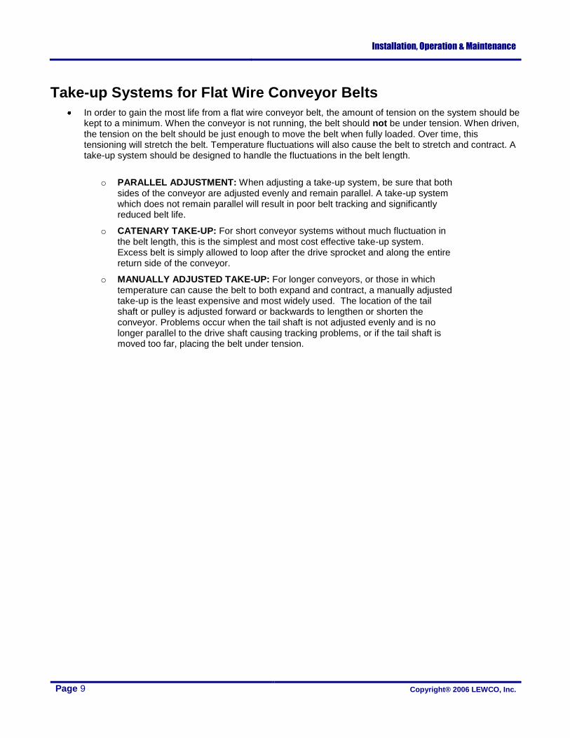
Take-up Systems for Flat Wire Conveyor Belts
In order to gain the most life from a flat wire conveyor belt, the amount of tension on the system should be kept to a minimum. When the conveyor is not running, the belt should not be under tension. When driven, the tension on the belt should be just enough to move the belt when fully loaded. Over time, this tensioning will stretch the belt. Temperature fluctuations will also cause the belt to stretch and contract. A take-up system should be designed to handle the fluctuations in the belt length.
o PARALLEL ADJUSTMENT: When adjusting a take-up system, be sure that both
sides of the conveyor are adjusted evenly and remain parallel. A take-up system which does not remain parallel will result in poor belt tracking and significantly reduced belt life.
o CATENARY TAKE-UP: For short conveyor systems without much fluctuation in the belt length, this is the simplest and most cost effective take-up system. Excess belt is simply allowed to loop after the drive sprocket and along the entire return side of the conveyor.
o MANUALLY ADJUSTED TAKE-UP: For longer conveyors, or those in which temperature can cause the belt to both expand and contract, a manually adjusted take-up is the least expensive and most widely used. The location of the tail shaft or pulley is adjusted forward or backwards to lengthen or shorten the conveyor. Problems occur when the tail shaft is not adjusted evenly and is no longer parallel to the drive shaft causing tracking problems, or if the tail shaft is moved too far, placing the belt under tension.
Installation, Operation & Maintenance
Page 10 Copyright® 2006 LEWCO, Inc.
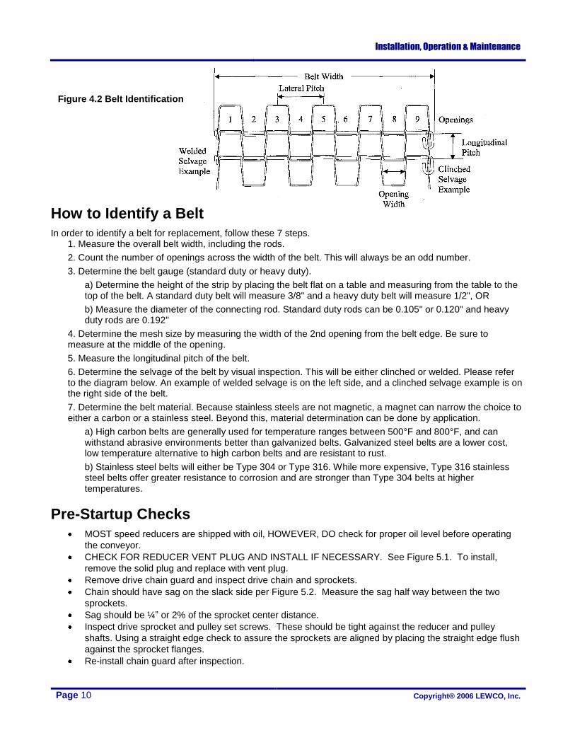
How to Identify a Belt
In order to identify a belt for replacement, follow these 7 steps. 1. Measure the overall belt width, including the rods.
2. Count the number of openings across the width of the belt. This will always be an odd number.
3. Determine the belt gauge (standard duty or heavy duty).
a) Determine the height of the strip by placing the belt flat on a table and measuring from the table to the top of the belt. A standard duty belt will measure 3/8" and a heavy duty belt will measure 1/2", OR
b) Measure the diameter of the connecting rod. Standard duty rods can be 0.105" or 0.120" and heavy duty rods are 0.192"
4. Determine the mesh size by measuring the width of the 2nd opening from the belt edge. Be sure to measure at the middle of the opening.
5. Measure the longitudinal pitch of the belt.
6. Determine the selvage of the belt by visual inspection. This will be either clinched or welded. Please refer to the diagram below. An example of welded selvage is on the left side, and a clinched selvage example is on the right side of the belt.
7. Determine the belt material. Because stainless steels are not magnetic, a magnet can narrow the choice to either a carbon or a stainless steel. Beyond this, material determination can be done by application.
a) High carbon belts are generally used for temperature ranges between 500°F and 800°F, and can withstand abrasive environments better than galvanized belts. Galvanized steel belts are a lower cost, low temperature alternative to high carbon belts and are resistant to rust.
b) Stainless steel belts will either be Type 304 or Type 316. While more expensive, Type 316 stainless steel belts offer greater resistance to corrosion and are stronger than Type 304 belts at higher temperatures.
Pre-Startup Checks
MOST speed reducers are shipped with oil, HOWEVER, DO check for proper oil level before operating
the conveyor.
CHECK FOR REDUCER VENT PLUG AND INSTALL IF NECESSARY. See Figure 5.1. To install,
remove the solid plug and replace with vent plug.
Remove drive chain guard and inspect drive chain and sprockets.
Chain should have sag on the slack side per Figure 5.2. Measure the sag half way between the two
sprockets.
Sag should be ¼” or 2% of the sprocket center distance.
Inspect drive sprocket and pulley set screws. These should be tight against the reducer and pulley
shafts. Using a straight edge check to assure the sprockets are aligned by placing the straight edge flush
against the sprocket flanges.
Re-install chain guard after inspection.
Figure 4.2 Belt Identification

Installation, Operation & Maintenance
Page 11 Copyright® 2006 LEWCO, Inc.
Maintenance
Effective operation and useful life of any equipment is directly related to the care and service it receives. A pre-determined maintenance schedule, including inspection, lubrication and cleaning should be established for each conveyor. Establish and maintain “Log Sheets” on each conveyor to record date and results of inspections, lubrication, and parts replacements. General inspections of all conveyors should be performed at regular intervals depending on use and service conditions.
Maintenance Intervals
The following chart gives a brief overview of what maintenance should be performed on a periodic basis.
COMPONENT ACTION SCHEDULE
WEEKLY MONTHLY QUARTERLY
MOTOR
Check noise.
Check temperature.
Check mounting bolts.
REDUCER
Check noise.
Check temperature.
Check oil level.
DRIVE CHAIN
Check tension.
Lubricate.
Check for wear.
SPROCKETS
Check for wear.
Check set screws and keys.
BELT
Check tracking.
Check tension.
Check lacing.
BEARINGS (Pulleys & rollers)
Check noise.
Check mounting bolts.
STRUCTURAL General check: Loose bolts etc. tightened.
Figure 5.2 Drive Chain Sag
Figure 5.1 Reducer Vent Plug Installation
Chain Too Tight
Approx. ¼" or 2% of sprocket centers
Sprocket Centers
Correct Slack Chain Too Loose
Installation, Operation & Maintenance
Page 12 Copyright® 2006 LEWCO, Inc.
Maintenance Procedures
Sprocket and Chain Maintenance
Remove drive chain guard and inspect drive chain and sprockets.
Chain should have ¼” or 2% sag when measured on the lower run of chain half way between the two
sprockets. See “Pre-Startup Checks”.
A loose chain can jump the drive sprockets and can cause sprocket wear and failure. A tight chain
requires excessive motor power, and can cause chain and sprocket failure.
Inspect drive sprocket and pulley set screws for tightness against the reducer and pulley shafts.
Check sprocket alignment. Misalignment causes wear on one side of the sprocket. Check for a
misaligned shaft or a sprocket off center.
Check shaft bearing set screws.
Lubricate the drive chain with SAE-30 oil approximately every 40 hours of operation. Lubricate more
frequently under extreme ambient conditions. Rinse chain in solvent before lubricating.
Re-install chain guard after inspection and maintenance.
Belt
Check front, back, and edges of belt for wear, breaks, and dirt accumulation. Clean belt with detergent
and water. Replace belt as required.
Check belt tension under load. The belt should be just tight enough to prevent excess slack with a rated
load. Loose belts cause jerky load movement. Tight belts cause breakage, web failure, and excessive
motor draw.
Check belt for broken, bent, loose, or missing clips and pins. Replace as required.
Motor and Reducer
Make sure the reducer is filled to the proper level with oil. Make sure breather hole is clean and the orifice
is open.
Inspect reducer for leaks.
Use only oil recommended by the reducer manufacturer.
Rollers, Belt Sprockets and Bearings
Check drive sprockets for broken teeth and/or key and/or keyway. Replace sprockets or keys as required.
Check all rollers for tightness. All rollers must rotate freely. If roller does not turn freely check for dirt
accumulation in bearing area and clean.
Check take-up belt sprockets. Only (1) should be keyed to shaft, the others should be able to rotate
(float) freely on the shaft.
Lubricate all flange type bearings that have grease fittings. Use a NLGI Grade 2 Lithium base grease,
Shell Alvania EP2, or equal. Snub roller and return roller bearings are not regreasable.
Listen to bearing for excessive noise. Replace as required.
Conveyor Bed and Supports
Check conveyor frame, splices, supports, and bearings for loose or missing hardware. Replace hardware
as required.
Cleaning
Periodically remove drive chains and clean by immersing in solvent and scrubbing with a wire brush.
Rinse thoroughly and re-lubricate. Verify proper chain tension.
Clean chain box and keep free of all debris.

Installation, Operation & Maintenance
Page 13 Copyright® 2006 LEWCO, Inc.
Troubleshooting
TROUBLE CAUSE SOLUTION
Conveyor does not start or motor stalls.
Motor overloaded. Check conveyor loading against design parameters.
Motor drawing excessive current. Check circuit breaker.
Excessive wear on drive chain and/or sprockets.
Lack of lubrication Lubricate chain.
Sprockets out of alignment. Align sprockets.
Loose drive chain. Correct chain slack (see Pre Startup Checks)
Loud popping and/or grinding noise. Defective bearing. Replace bearing.
Loose drive sprocket set screw. Tighten sprocket set screws and check key.
Loose drive chain. Correct chain slack (see Pre Startup Checks)
Motor or reducer overheating. (Note: many motors and reducers can be hot to the touch and still be operating within normal parameters.)
Conveyor overloaded. Check conveyor loading against design parameters.
Low voltage to motor. Correct voltage level as stated on motor name plate.
Reducer lubricant level low. Fill reducer reservoir.
Belt runs to one side of conveyor at a given point.
Idler rolls just prior to the trouble point are not perpendicular to the belt travel.
Adjust the idler rolls so they are perpendicular to the travel.
Idler rolls just prior to the trouble point are not level. Adjust the idler rolls so they are level within +/- 1/32”.
Idler rolls just prior to the trouble point are sticking or built up with debris.
Clean and lubricate the idlers.
Conveyor frame bent or not level. Check the level and straightness of the conveyor frame and fix if necessary.
Same section of belt runs to one side at all points of conveyor.
That section of belt has become damaged. Replace the section of belt which is causing the problem.
Belt wearing along one side. Conveyor not aligned properly. Check the alignment of the conveyor (see the section on alignment and tracking). Belt not tracked properly.
Belt tracking to one side along entire conveyor.
Conveyor not aligned properly. Belt not tracked properly.
Check the alignment of the conveyor (see the section on alignment and tracking).
Uneven loading of belt. Adjust the loading on the belt.
Distance from the return rollers to the tail shaft is too large.
Reduce the distance or provide support for the belt across this distance.
Belt stretching on one side. Drive and tail sprockets not parallel. Check the alignment of the drive and tail sprockets (see section on alignment and tracking).
Belt stretching. Excessive heat. Reduce temperature or choose belt material more suited to temperature.
Belt tension too high. Reduce the load on the belt. The belt should not be tensioned on the return side.
Sprocket teeth wearing. Belt tension too high. Reduce the load on the belt. The belt should not be tensioned on the return side.
Belt tracking to one side and riding on sprocket teeth.
Check the alignment of the conveyor (see the section on alignment and tracking
Sprockets not mounted so they engage the belt in the center of the openings.
Tighten set screws (drive sprockets). Place shaft collars on both sides of sprockets to hold in place (tail sprockets).
Not enough sprockets. Add more sprockets.
Sprocket teeth not engaging belt. Keyway of shaft driving sprockets not cut straight. Replace shaft.
Sprockets not mounted with facing same direction.
Remount sprockets so all the hubs are facing the same direction.
Shaft driving sprockets is bowing.
Replace with larger shaft or add additional support bearings.

Installation, Operation & Maintenance
Page 14 Copyright® 2006 LEWCO, Inc.
TROUBLE CAUSE SOLUTION
Belt not releasing from drive sprockets.
The belt is wrapping more than 150 degrees around the drive sprockets.
Limit belt wrap to 150 degrees. Add a stripper roll to pull the belt from the sprocket.
Belt tension too high. Reduce the load on the belt. The belt should not be tensioned on the return side.
Belt riding up on sprocket teeth.
Belt tension too high. Reduce the load on the belt. The belt should not be tensioned on the return side.
Longitudinal pitch of conveyor belt too short. Check the longitudinal pitch (distance from one connecting rod to the next rod). East coast pitch is 1.084”. West coast pitch is 1.054”. For true 1/2” x 1/2” belt it is 0.542”.
Belt or support surface is wearing. Sprockets for a standard duty belt are being used to drive a heavy duty belt.
S-series sprockets for standard duty belts will not work on a heavy duty belt.
There is too much friction between the belt and the support surface.
Lubricate the support surface to reduce the friction.
The support surface is rough, causing the belt to wear.
Check for debris between the belt and the supports. Debris of even relatively soft materials can have sharp edges which will cause a belt to wear quickly.
The belt and the support surface are made of the same or similar materials. Change the support bed to lower friction, dissimilar material.
Longitudinal supports are wearing grooves into the underside of the belt.
Add more supports across the width of the belt or stagger the supports. See the section on belt supports.
Replacement Parts
How to Order
Provide the MODEL NUMBER, and SERIAL NUMBER [located on unit label], when ordering parts for your LEWCO Conveyor. There is one unit label on each section of conveyor. To order parts please contact your local LEWCO distributor. If unable to contact your local distributor or the original distributor that supplied the equipment, please contact LEWCO, Inc. by phone at 419-625-4014, or Fax 419-625-1247. Ask for the conveyor sales parts department.
LEWCO, Inc. Serial No.: 026563-001
Model No.: MDSWM-12-120-60-36-36-B20-D28-G99-M99- A11-SCC10-P94
Section No.: 026563-001-01
Figure 7.1 Location of Serial Number, Model Number, and Section Number on Typical Unit Label

Installation, Operation & Maintenance
Page 15 Copyright® 2006 LEWCO, Inc.
ITEM PART NO. DESCRIPTION
1 CVP0702-LG RAIL,STYLE N,INT,11GAX7.25X1.5
2 CVS1518-LG CROSSTIE,CHAN,WELDMENT,MDRWM
3 PCP1224 ROLLER SLIDE CLIP,HAT SHAPE,7/16
4 CVS0003-BRG-LG-ROLCOV ROLLER,R1916,A11 BEARING
5 CVP1313-LG WEAR STRIP,UHMW,MDSWM,3"WIDE 1/4THK
6 CVP0127-LG CROSSTIE,ANGLE,35 TIE
ITEM PART NO. DESCRIPTION
1 CVP0732 DRIVE PL,END,6 SPRKT,MDRWM\MDSWM
2 PCP0200 BEARING,2 BOLT FLG,ECC LOCK,1-3/16
3 CVP0734-LG SHAFT,DRIVE,1-3/16" W/FULL KWY
4 PCP0484 SPROCKET,FLAT WIRE,1/2X1,18TH,KEY
5 PCP0484 SPROCKET,FLAT WIRE,1/2X1,18TH,KEY
6 PCP0719 KEYSTOCK,SQUARE,1/4 SQ X 1 LONG
7 CVP0127-LG CROSSTIE,ANGLE,35 TIE
ITEM PART NO. DESCRIPTION
1 CVS0714 TKUP PL WD,RH,6 SPRKT,MDRWM\MDSW
2 CVS0713 TKUP PL WD,LH,6 SPRKT,MDRWM\MDSW
3 CVP0261 BEARING SLIDE CLIP,LH,F206,1/4 PLT
4 CVP0228 BEARING SLIDE CLIP,RH,F206,1/4 PLT
5 PCP0200 BEARING,2 BOLT FLG,ECC LOCK,1-3/16
6 PCP0484 SPROCKET,FLAT WIRE,1/2X1,18TH,KEY
7 PCP0500 SPROCKET,FLAT WIRE,1/2X1,18TH,NOKEY
8 PCP0719 KEYSTOCK,SQUARE,1/4 SQ X 1 LONG
9 CVP0733-LG SHAFT,TAKE-UP,1-3/16 W/6.5" KWY
10 CVP0127-LG CROSSTIE,ANGLE,35 TIE
Figure 8.1 MDSWM Conveyor (less drive and supports)
Standard Spare Part Listings
Figure 8.2 Drive Pulley
Figure 8.3 Takeup Pulley

Installation, Operation & Maintenance
Page 16 Copyright® 2006 LEWCO, Inc.
ITEM PART NO. DESCRIPTION
1 CVS0171-CASE-LG DRIVE MOUNT,CHAN WELD,GROVE,BTM MNT
2 CVP0278 GUARD MOUNTING BRKT,ANG,8-3/8
3 CVP0264-CASE DRIVE TENSIONER,GROVE REDUCER
4 PCP0128-30-3-56C REDUCER,GROVE BM226,SINGLE REDTN
PCP0128-RATIO-OS-MOUNT REDUCER, OTHER
5 CVS0177-21 DRIVE GRD ASS'Y,NOM. 8" DIA
CVS0177-GC DRIVE GRD ASS’Y, OTHER
6 PCP0267-13-1.250 SPROCKET,#50 B STYLE,KWY & 2 SS
PCP0267-TH-BORE SPROCKET, OTHER
7 PCP0267-22-1.187 SPROCKET,#50 B STYLE,KWY & 2 SS
PCP0267-TH-BORE SPROCKET, OTHER
8 PCP0719 KEYSTOCK,SQUARE,1/4 SQ X 1 LONG
9 PCP0156 MOTOR,1/2HP,230-460/3/60,56C,TEFC
ABBREVIATION DESCRIPTION
BF BETWEEN FRAME
LG LENGTH
BRG BEARING
OAW OVERALL WIDTH
SPKT SPROCKET STYLE
TH NO. OF TEETH
ROLCOV ROLLER COVER
PTCH NO. OF PITCHES
CASE REDUCER CASE SIZE
NS NO. OF STRANDS
RATIO REDUCTION RATIO
OS OUTPUT SHAFT ASSY
MOUNT MOTOR MOUNT SIZE
TH NO. OF TEETH
GC GUARD CENTER TO CENTER
BORE BORE SIZE
CC CHAIN CENTER
BW BELT WIDTH
RCC ROLLER CENTER TO CENTER
Figure 8.5 Side Drive
D24 Right Side
D25 Left Side (Shown Above
Figure 8.4 End Drive
D28 Right Side (Shown Above)
D29 Left Side
Note: Motor, speed reducer, driver, and driven sprockets will vary
depending on drive option, conveyor speed and motor horsepower.
Contact our parts department for specific components listed by the
assigned serial number.
ABBREVIATION KEY
Figure 8.6 Side Drive
D26 Right Side (Shown Above)
D27 Left Side