installation, operation and maintenance … · level of safety during installation, start-up, opera...
TRANSCRIPT

INSTALLATION, OPERATION AND MAINTENANCE INSTRUCTIONS
Screw Compressor Water-Cooled Liquid Chillers
30HXC 080-375
Original instructions
Nominal cooling capacity 30HXC: 286-1300 kW 50 Hz / 60Hz
2
CONTENTS
1 - INTRODUCTION ..................................................................................................................................................................... 41.1 - Installation safety considerations ........................................................................................................................................... 41.2 - Equipment and components under pressure ......................................................................................................................... 51.3 - Maintenance safety considerations ......................................................................................................................................... 51.4 - Repair safety considerations ................................................................................................................................................... 7
2 - PRELIMINARY CHECKS ...................................................................................................................................................... 82.1 - Check equipment received ...................................................................................................................................................... 82.2 - Moving and siting the unit ....................................................................................................................................................... 9
3 - DIMENSIONS, CLEARANCES, WEIGHT DISTRIBUTION ....................................................................................... 103.1 - 30HXC 080-190 ....................................................................................................................................................................... 103.2 - 30HXC 200-375 ...................................................................................................................................................................... 113.3 - Multiple chiller installation ................................................................................................................................................... 12
4 - PHYSICAL AND ELECTRICAL DATA - STANDARD 50HZ APPLICATION ....................................................... 134.1 - Physical data 30HXC ............................................................................................................................................................. 134.2 - Electrical data 30HXC ........................................................................................................................................................... 144.3 - Compressor electrical data 30HXC ...................................................................................................................................... 154.4 - Electrical data for 30HXC units with high condensing temperatures (option 150/150A) ............................................. 154.5 - Compressor electrical data 30HXC + option 150/150A ..................................................................................................... 16
5 - PHYSICAL AND ELECTRICAL DATA - OPTIONAL 60HZ APPLICATION (OPTION 60/61) ......................... 175.1 - Physical data - 30HXC + option 60 (460V-3ph-60Hz) ....................................................................................................... 175.2 - Electrical data - 30HXC + option 60 .................................................................................................................................... 185.3 - Electrical data - 30HXC + option 60 with high condensing temperature (options 150/150A) ..................................... 195.4 - Physical data - 30HXC + option 61 (380V-3ph-60Hz) ....................................................................................................... 205.5 - Electrical data - 30HXC + option 61 .................................................................................................................................... 215.6 - Electrical data - 30HXC + option 61 with high condensing temperature (options 150/150A) ..................................... 225.7 - Compressor electrical data - 30HXC + option 60/61 ......................................................................................................... 225.8 - Compressor electrical data - 30HXC + option 60/61 + option 150/150A ........................................................................ 23
6 - UNIT CHARACTERISTICS FOR 30HXC UNITS WITH VERY LOW TEMPERATURE OPTION (OPTION 6 - OUT OF CE MARKING) .............................................................................................................................. 236.1 - Options and accessories ......................................................................................................................................................... 236.2 - Operating range, 30HXC units with very low temperature option .................................................................................. 236.3 - Evaporator water flow (l/s) for 35% ethylene glycol ......................................................................................................... 246.4 - Evaporator pressure drop curve, units for very low temperature ..................................................................................... 25
7 - APPLICATION DATA ........................................................................................................................................................... 267.1 - Unit operating range ............................................................................................................................................................... 267.2 - Minimum chilled water flow .................................................................................................................................................. 267.3 - Maximum chilled water flow .................................................................................................................................................. 267.4 - Variable flow evaporator ........................................................................................................................................................ 277.5 - System minimum water volume ............................................................................................................................................ 277.6 - Cooler flow rate (l/s) ............................................................................................................................................................... 277.7 - Condenser flow rate (l/s) ........................................................................................................................................................ 277.8 - Evaporator pressure drop curve ............................................................................................................................................ 287.9 - Condenser pressure drop curve ............................................................................................................................................. 28
8 - ELECTRICAL CONNECTION ............................................................................................................................................ 298.1 - Electrical connections 30HXC units .................................................................................................................................... 298.2 - Power supply ........................................................................................................................................................................... 308.3 - Voltage phase imbalance (%) ............................................................................................................................................... 308.4 - Recommended wire sections ................................................................................................................................................. 31

3
The cover illustrations are for illustrative purposes only and are not part of any offer for sale or contract.
9 - WATER CONNECTIONS ...................................................................................................................................................... 369.1 - Operating precautions ........................................................................................................................................................... 369.2 - Water connections .................................................................................................................................................................. 369.3 - Flow control ............................................................................................................................................................................ 379.4 - Evaporator and condenser for the 30HXC water box bolt tightening ............................................................................ 389.5 - Frost protection ...................................................................................................................................................................... 389.6 - Operation of two units in master/slave mode ..................................................................................................................... 38
10 - MAJOR SYSTEM COMPONENTS AND OPERATION DATA ................................................................................. 3910.1 - Geared twin screw compressor ........................................................................................................................................... 3910.2 - Pressure vessels ..................................................................................................................................................................... 3910.3 - Electronic expansion device (EXV) .................................................................................................................................. 4010.4 - Economizer ........................................................................................................................................................................... 4010.5 - Oil pumps .............................................................................................................................................................................. 4010.6 - Motor cooling valves ............................................................................................................................................................ 40
11 - MAIN OPTIONS AND ACCESSORIES ........................................................................................................................... 4111.1 - Compressor suction valves (option 92) .............................................................................................................................. 4211.2 - Electric protection level of the 30HXC control boxes to IP44C (option 20) ............................................................... 4211.3 - Tropicalised control box for 30HXC units (option 22) ..................................................................................................... 4211.4 - Disassembled 30HXC units (option 51) ............................................................................................................................ 4211.5 - Brine units for low-temperature evaporator leaving applications (option 5)................................................................ 42
12 - MAINTENANCE ................................................................................................................................................................... 4212.1 - Maintenance instructions .................................................................................................................................................... 4212.2 - Soldering and welding.......................................................................................................................................................... 4212.3 - Refrigerant charging - adding charge ................................................................................................................................. 4212.4 - Indication of low charge on a 30HXC system ................................................................................................................... 4312.5 - Electrical maintenance ........................................................................................................................................................ 4312.6 - Pressure transducers ............................................................................................................................................................ 4312.7 - Oil charging - low oil recharging ........................................................................................................................................ 4312.8 - Integral oil filter change ....................................................................................................................................................... 4412.9 - Filter change-out schedule .................................................................................................................................................. 4412.10 - Filter change-out procedure .............................................................................................................................................. 4412.11 - Compressor replacement ................................................................................................................................................... 4412.12 - Corrosion control ............................................................................................................................................................... 45
13 - START-UP CHECKLIST FOR 30HXC LIQUID CHILLERS (USE FOR JOB FILE) ............................................ 46

4
1 - INTRODUCTION
Prior to the initial start-up of the 30HXC units, the people involved in the on-site installation, start-up, operation and maintenance of this unit should be thoroughly familiar with these instructions and the specific project data for the installation site.
The 30HXC liquid chillers are designed to provide a very high level of safety during installation, start-up, opera tion and maintenance. They will provide safe and reliable service when operated within their application range.
This manual provides the necessary information to familiarize yourself with the control system before performing start-up procedures. The procedures in this manual are arranged in the sequence required for machine installation, start-up, operation and maintenance.
Be sure you understand and follow the procedures and safety precautions contained in the instructions supplied with the machine, as well as those listed in this guide.
To find out, if these products comply with European directives (machine safety, low voltage, electromagnetic compatibility, equipment under pressure etc.) check the declarations of conformity for these products.
1.1 - Installation safety considerations
Access to the unit must be reserved to authorised personnel, qualified and trained in monitoring and maintenance. The access limitation device must be installed by the customer (e.g. cut-off, enclosure).
After the unit has been received, when it is ready to be installed or reinstalled, and before it is started up, it must be inspected for damage. Check that the refrigerant circuit(s) is (are) intact, especially that no components or pipes have shifted (e.g. following a shock). If in doubt, carry out a leak tightness check and verify with the manufacturer that the circuit integrity has not been impaired. If damage is detected upon receipt, immediately file a claim with the shipping company.
Carrier strongly recommends employing a specialised company to unload the machine.
It is compulsory to wear personal protection equipment.
Do not remove the skid or the packaging until the unit is in its final position. These units can be moved with a fork lift truck, as long as the forks are positioned in the right place and direction on the unit.
The units can also be lifted with slings, using only the designated lifting points marked on the unit.
Use slings or lifting beams with the correct capacity, and always follow the lifting instructions on the certified drawings supplied with the unit. Do not tilt the unit more than 15°.
Safety is only guaranteed, if these instructions are carefully followed. If this is not the case, there is a risk of material deterioration and injuries to personnel.
Never cover any protection devices.
This applies to the relief valves (if used) in the refrigerant or heat transfer medium circuits, the fuse plugs and the pressure switches.
Ensure that the valves are correctly installed, before operating the unit.
Classification and control In accordance with the Pressure Equipment Directive and national usage monitoring regulations in the European Union the protection devices for these machines are classified as follows:
Safety accessory*
Damage limitation accessory** in case of an external fire
Refrigerant sideHigh-pressure switch xExternal relief valve*** xRupture disk xFuse plug xHeat transfer fluid sideExternal relief valve **** ****
* Classifiedforprotectioninnormalservicesituations.** Classifiedforprotectioninabnormalservicesituations.*** The instantaneous over-pressure limited to 10% of the operating pressure
doesnotapplytothisabnormalservicesituation.Thecontrolpressurecanbehigherthantheservicepressure.Inthiscaseeitherthedesigntemperatureorthe high-pressure switch ensures that the service pressure is not exceeded in normalservicesituations.
**** Theclassificationofthesereliefvalvesmustbemadebythepersonnelthatcompletesthewholehydronicinstallation.
If the relief valves are installed on a change-over valve, this is equipped with a relief valve on each of the two outlets. Only one of the two relief valves is in operation, the other one is isolated. Never leave the change-over valve in the intermediate position, i.e. with both ways open (bring the actuator in abutment, front or back according to the outlet to isolate). If a relief valve is removed for checking or replacement please ensure that there is always an active relief valve on each of the change-over valves installed in the unit.
All factory-installed relief valves are lead-sealed to prevent any calibration change.
The external relief valves and the fuses are designed and installed to ensure damage limitation in case of a fire.
In accordance with the regulations applied for the design, the European directive on equipment under pressure and in accordance with the national usage regulations:
• These relief valves and fuses are not safety accessories but damage limitation accessories in case of a fire,
• The high pressure switches are the safety accessories.
The relief valve must only be removed if the fire risk is fully controlled and after checking that this is allowed by local regulations and authorities. This is the responsibility of the operator.
5
When the unit is subjected to fire, safety devices prevent rupture due to over-pressure by releasing refrigerant. The fluid may then be decomposed into toxic residues when subjected to the flame: • Stay away from the unit • Set up warnings and recommendations for personnel in
charge to stop the fire. • Fire extinguishers appropriate to the system and the
refrigerant type must be easily accessible.
The external relief valves must in principle be connected to discharge pipes for units installed in a room. Refer to the installation regulations, for example those of European standards EN 378 and EN 13136.
They include a sizing method and examples for configuration and calculation. Under certain conditions these standards permit connection of several valves to the same discharge pipe. Note: Like all other standards these EN standards are available from national standards organisations.
These pipes must be installed in a way that ensures that people and property are not exposed to refrigerant leaks. These fluids may be diffused in the air, but far away from any building air intake, or they must be discharged in a quantity that is appropriate for a suitably absorbing environment.
It is recommended to install an indicating device to show if part of the refrigerant has leaked from the valve. The presence of oil at the outlet orifice is a useful indicator that refrigerant has leaked. Keep this orifice clean to ensure that any leaks are obvious.
The calibration of a valve that has leaked is generally lower than its original calibration. The new calibration may affect the operating range. To avoid a nuisance tripping or leaks, replace or re-calibrate the valve.
Periodic check of the relief valves: See paragraph 1.3 “Maintenance safety considerations”.
Provide a drain in the discharge circuit, close to each relief valve, to avoid an accumulation of condensate or rain water.
Ensure good ventilation, as accumulation of refrigerant in an enclosed space can displace oxygen and cause asphyxiation or explosions.
Inhalation of high concentrations of vapour is harmful and may cause heart irregularities, unconsciousness, or death. Vapour is heavier than air and reduces the amount of oxygen available for breathing. These products cause eye and skin irritation. Decomposition products are hazardous.
1.2 - Equipment and components under pressure
The units are intended to be stored and operate in an environment where the ambient temperature must not be less than the lowest allowable temperature indicated on the nameplate. See section “10.2 - Pressure vessels”.
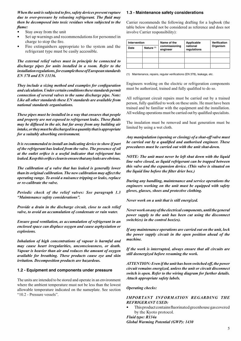
1.3 - Maintenance safety considerations
Carrier recommends the following drafting for a logbook (the table below should not be considered as reference and does not involve Carrier responsibility):
Intervention Name of the commissioning engineer
Applicable national regulations
Verification OrganismDate Nature (1)
(1) Maintenance,repairs,regularverifications(EN378),leakage,etc.
Engineers working on the electric or refrigeration components must be authorized, trained and fully qualified to do so.
All refrigerant circuit repairs must be carried out by a trained person, fully qualified to work on these units. He must have been trained and be familiar with the equipment and the installation. All welding operations must be carried out by qualified specialists.
The insulation must be removed and heat generation must be limited by using a wet cloth.
Any manipulation (opening or closing) of a shut-off valve must be carried out by a qualified and authorised engineer. These procedures must be carried out with the unit shut-down.
NOTE: The unit must never be left shut down with the liquid line valve closed, as liquid refrigerant can be trapped between this valve and the expansion device. (This valve is situated on the liquid line before the filter drier box.)
During any handling, maintenance and service operations the engineers working on the unit must be equipped with safety gloves, glasses, shoes and protective clothing.
Never work on a unit that is still energized.
Never work on any of the electrical components, until the general power supply to the unit has been cut using the disconnect switch(es) in the control box(es).
If any maintenance operations are carried out on the unit, lock the power supply circuit in the open position ahead of the machine.
If the work is interrupted, always ensure that all circuits are still deenergized before resuming the work.
ATTENTION: Even if the unit has been switched off, the power circuit remains energized, unless the unit or circuit disconnect switch is open. Refer to the wiring diagram for further details. Attach appropriate safety labels.
Operating checks:
IMPORTANT INFORMATION REGARDING THE REFRIGERANT USED: • This product contains fluorinated greenhouse gas covered
by the Kyoto protocol.Fluid type: R134a Global Warming Potential (GWP): 1430
6
Consult Carrier Service for this type of test. Carrier mentions here only the principle of a test without removing the pressure switch:
- Verify and and record the setpoints of pressure switches and relief devices (valves and possible rupture discs)
- Be ready to switch-off the main disconnect switch of the power supply if the pressure switch does not trigger (avoid over-pressure or excess gas in case of valves on the high-pressure side with the recovery condensers)
- Connect a calibrated pressure gauge (the values displayed on the user interface may be inaccurate in an instant reading because of the scanning delay applied in the control)
- Neutralise the HP soft value - Cut the condenser water flow - Check the cut-off value - Reactivate HP soft value - Reactivate manually HP switch.
CAUTION: If the test leads to replacing the pressure switch, it is necessary to recover the refrigerant charge, these pressure switches are not installed on automatic valves (Schraeder type).
At least once a year thoroughly inspect the protection devices (valves). If the machine operates in a corrosive environment, inspect the protection devices more frequently.
Regularly carry out leak tests and immediately repair any leaks.
Ensure regularly that the vibration levels remain acceptable and close to those at the initial unit start-up.
Before opening a refrigerant circuit, purge and consult the pressure gauges.
Change the refrigerant when there are equipment failures, following a procedure such as the one described in NF E29-795 or carry out a refrigerant analysis in a specialist laboratory.
If the refrigerant circuit remains open for longer than a day after an intervention (such as a component replacement), the openings must be plugged and the circuit must be charged with nitrogen (inertia principle). The objective is to prevent penetration of atmospheric humidity and the resulting corrosion on the internal walls and on non-protected steel surfaces.
CAUTION:
1. Any handling of refrigerant contained in this product must comply with the F-Gas Directive N° 517/2014 and any other applicable local legislation.
2. Ensure that the refrigerant is never released to the atmosphere during installation, maintenance or equipment disposal.
3. The deliberate gas release into the atmosphere is strictly not allowed.
4. If a refrigerant leak is detected, ensure that it is stopped and repaired as quickly as possible.
5. Only a qualified and certified personnel can perform installation operations, maintenance, refrigerant circuit leak test as well as the equipment disposal and the refrigerant recovering.
6. The gas recovery for recycling, regeneration or destruction is at customer charge.
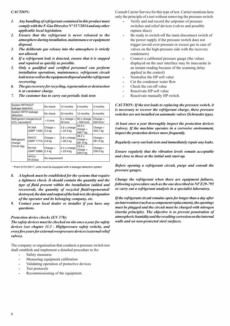
7. The customer has to carry out periodic leak tests
SystemWITHOUTleakage detection No check 12 months 6 months 3 months
SystemWITHleakagedetection No check 24 months 12 months 6 months
Refrigerant charge/circuit (CO2 equivalent) < 5 tons 5≤charge<
50 tons50≤charge< 500 tons
Charge > 500 tons*
Refrigerant charge/Circuit (kg)
R134A (GWP 1430)
Charge < 3.5kg
3.5≤charge<34.9kg
34.9≤charge < 349.7kg
Charge > 349.7kg
R407C(GWP1774)
Charge < 2.8kg
2.8≤charge<28.2kg
28.2≤charge < 281.9kg
Charge > 281.9kg
R410A (GWP 2088)
Charge < 2.4kg
2.4≤charge<23.9kg
23.9≤charge < 239.5kg
Charge > 239.5kg
HFO’s: R1234ze No requirement
*From01/01/2017,unitsmustbeequippedwithaleakagedetectionsystem
8. A logbook must be established for the systems that require a tightness check. It should contain the quantity and the type of fluid present within the installation (added and recovered), the quantity of recycled fluid/regenerated/destroyed, the date and output of the leak test, the designation of the operator and its belonging company, etc.
9. Contact your local dealer or installer if you have any questions.
Protection device checks (EN 378):The safety devices must be checked on site once a year for safety devices (see chapter 11.3 - Highpressure safety switch), and every five years for external overpressure devices (external relief valves).
The company or organisation that conducts a pressure switch test shall establish and implement a detailed procedure to fix:
- Safety measures - Measuring equipment calibration - Validating operation of protective devices - Test protocols - Recommissioning of the equipment.

7
1.4 - Repair safety considerations
It is compulsory to wear personal protection equipment.
The insulation must be removed and warming up must be limited by using a wet cloth.
Before opening the unit always ensure that the circuit has been purged.
If work on the evaporator is required, ensure that the piping from the compressor is no longer pressurised (as the valve is not leaktight in the compressor direction.)
All installation parts must be maintained by the personnel in charge, in order to avoid material deterioration and injuries to people. Faults and leaks must be repaired immediately. The authorized technician must have the responsibility to repair the fault immediately. Each time repairs have been carried out to the unit, the operation of the protection devices must be re-checked.
Comply with the regulations and recommendations in unit and HVAC installation safety standards, such as: EN 378, ISO 5149, etc.
If a leak occurs or if the refrigerant becomes contaminated (e.g. by a short circuit in a motor) remove the complete charge using a recovery unit and store the refrigerant in mobile containers.
Repair the leak detected and recharge the circuit with the total R-134a charge, as indicated on the unit name plate. Certain parts of the circuit can be isolated. Only charge liquid refrigerant R-134a at the liquid line.
Ensure that you are using the correct refrigerant type before recharging the unit.
Charging any refrigerant other than the original charge type (R-134a) will impair machine operation and can even lead to a destruction of the compressors. The compressors operating with this refrigerant type are lubricated with a synthetic polyolester oil.
RISK OF EXPLOSION:
Do not use oxygen to purge lines or to pressurize a machine for any purpose. Oxygen gas reacts violently with oil, grease, and other common substances.
Never exceed the specified maximum operating pressures. Verify the allowable maximum high- and low-side test pressures by checking the instructions in this manual and the pressures given on the unit name plate.
Do not use air for leak testing. Use only refrigerant or dry nitrogen.
Do not unweld or flamecut the refrigerant lines or any refrigerant circuit component until all refrigerant (liquid and vapour) has been removed from chiller. Traces of vapour should be displaced with dry air nitrogen. Refrigerant in contact with an open flame produces toxic gases.
The necessary protection equipment must be available, and appropriate fire extinguishers for the system and the refrigerant type used must be within easy reach.
Do not siphon refrigerant.
Avoid contact with liquid refrigerant on the skin or splashing it into the eyes. Use safety goggles. Wash any spills from the skin with soap and water. If liquid refrigerant enters the eyes, immediately and abundantly flush the eyes with water and consult a doctor.
The accidental releases of the refrigerant, due to small leaks or significant discharges following the rupture of a pipe or an unexpected release from a relief valve, can cause frostbites and burns to personnel exposed. Do not ignore such injuries. Installers, owners and especially service engineers for these units must: - Seek medical attention before treating such injuries. - Have access to a first-aid kit, especially for treating eye
injuries.We recommend to apply standard EN 378-3 Annex 3.
Never apply an open flame or live steam to a refrigerant container. Dangerous overpressure can result. If it is necessary to heat refrigerant, use only warm water.
During refrigerant removal and storage operations follow applicable regulations. These regulations, permitting conditioning and recovery of halogenated hydrocarbons under optimum quality conditions for the products and optimum safety conditions for people, property and the environment are described in standard NF E29-795.
Any refrigerant transfer and recovery operations must be carried out using a transfer unit. A 3/8” SAE connector on the manual liquid line valve is supplied with all units for connection to the transfer station. The units must never be modified to add refrigerant and oil charging, removal and purging devices. All these devices are provided with the units. Please refer to the certified dimensional drawings for the units.
Do not re-use disposable (non-returnable) cylinders or attempt to refill them. It is dangerous and illegal. When cylinders are empty, evacuate the remaining gas pressure, and move the cylinders to a place designated for their recovery. Do not incinerate.
ATTENTION: Only use refrigerant R134a, in accordance with 700 AHRI (Air conditioning, Heating and Refrigeration Institute). The use of any other refrigerant may expose users and operators to unexpected risks.
Do not attempt to remove refrigerant circuit components or fittings, while the machine is under pressure or while it is running. Be sure pressure is at 0 kPa before removing components or opening a circuit.
Do not attempt to repair or recondition any safety devices when corrosion or build-up of foreign material (rust, dirt, scale, etc.) is found within the valve body or mechanism. If necessary, replace the device. Do not install relief valves in series or backwards.
8
2 - PRELIMINARY CHECKS
2.1 - Check equipment received
• Inspect the unit for damage or missing parts. If damage is detected, or if shipment is incomplete, immediately file a claim with the shipping company.
• Confirm that the unit received is the one ordered. Compare the name plate data with the order.
• The unit name plate must include the following information: - Version number - Model number - CE marking - Serial number - Year of manufacture and test date - Fluid being transported - Refrigerant used and refrigerant class - Refrigerant charge per circuit - Containment fluid to be used - PS: Min./max. allowable pressure (high and low
pressure side) - TS: Min./max. allowable temperature (high and low
pressure side) - Pressure switch cut-out pressures - Unit leak test pressure - Voltage, frequency, number of phases - Maximum current drawn - Maximum power input - Unit net weight
• Confirm that all accessories ordered for on-site installation have been delivered, and are complete and undamaged.
The unit must be checked periodically during its whole operating life to ensure that no shocks (handling accessories, tools etc.) have damaged it. If necessary, the damaged parts must be repaired or replaced. See also chapter 12 “Standard maintenance”.
ATTENTION: No part of the unit must be used as a walk-way, rack or support. Periodically check and repair or if necessary replace any component or piping that shows signs of damage.
The refrigerant lines can break under the weight and release refrigerant, causing personal injury.
Do not climb on a machine. Use a platform, or staging to work at higher levels.
Use mechanical lifting equipment (crane, hoist, winch, etc.) to lift or move heavy components. For lighter components, use lifting equipment when there is a risk of slipping or losing your balance.
Use only original replacement parts for any repair or component replacement. Consult the list of replacement parts that corresponds to the specification of the original equipment.
Do not drain water circuits containing industrial brines, without informing the technical service department at the installation site or a competent body first.
Close the entering and leaving water shutoff valves and purge the unit water circuit, before working on the components installed on the circuit (screen filter, pump, water flow switch, etc.).
Do not loosen the water box bolts until the water boxes have been completely drained.
Periodically inspect all valves, fittings and pipes of the refrigerant and hydronic circuits to ensure that they do not show any corrosion or any signs of leaks.
It is recommended to wear ear defenders, when working near the unit and the unit is in operation.
9
2.2 - Moving and siting the unit
2.2.1 - Moving
See chapter 1.1 “Installation safety considerations”.
CAUTION: Only use slings at the designated lifting points which are marked on the unit.
2.2.2 - Siting the unit
Always refer to the chapter “Dimensions and clearances” to confirm that there is adequate space for all connections and service operations. For the centre of gravity coordinates, the position of the unit mounting holes, and the weight distribution points, refer to the certified dimensional drawing supplied with the unit.
Typical applications of these units are in refrigeration systems, and they do not require earthquake resistance. Earthquake resistance has not been verified.
Before siting the unit check that: • the permitted loading at the site is adequate or that
appropriate strenghtening measures have been taken. • the unit is installed level on an even surface (maximum
tolerance is 5 mm in both axes). • there is adequate space above the unit for air flow and
to ensure access to the components. • the number of support points is adequate and that they
are in the right places. • the location is not subject to flooding.
CAUTION: Lift and set down the unit with great care. Tilting and jarring can damage the unit and impair unit operation.
2.2.3 - Checks before system start-up
Before the start-up of the refrigeration system, the complete installation, including the refrigeration system must be verified against the installation drawings, dimensional drawings, system piping and instrumentation diagrams and the wiring diagrams.
During the installation test national regulations must be followed. If no national regulation exists, standard EN 378 can be used as a guide.
• External visual installation checks: • Ensure that the machine is charged with refrigerant.
Verify on the unit nameplate that the ‘fluid being transported’ is R-134a and is not nitrogen.
• Compare the complete installation with the refrigeration system and power circuit diagrams.
• Check that all components comply with the design specifications.
• Check that all protection documents and equipment provided by the manufacturer (dimensional drawings, P&ID, declarations etc.) to comply with the regulations are present.
• Verify that the environmental safety and protection and devices and arrangements provided by the manufacturer to comply with the regulations are in place.
• Verify that all document for pressure containers, certificates, name plates, files, instruction manuals provided by the manufacturer to comply with the regulations are present.
• Verify the free passage of access and safety routes. • Check that ventilation in the plant room is adequate. • Check that refrigerant detectors are present. • Verify the instructions and directives to prevent the
deliberate removal of refrigerant gases that are harmful to the environment.
• Verify the installation of connections. • Verify the supports and fixing elements (materials, routing
and connection). • Verify the quality of welds and other joints. • Check the protection against mechanical damage. • Check the protection against heat. • Check the protection of moving parts. • Verify the accessibility for maintenance or repair and
to check the piping. • Verify the status of the valves. • Verify the quality of the thermal insulation and of the
vapour barriers.
10
3 - DIMENSIONS, CLEARANCES, WEIGHT DISTRIBUTION
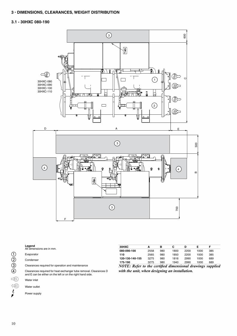
3.1 - 30HXC 080-190
30HXC A B C D E F080-090-100 2558 980 1800 2200 1000 385110 2565 980 1850 2200 1000 385120-130-140-155 3275 980 1816 2990 1000 689175-190 3275 980 1940 2990 1000 689NOTE: Refer to the certified dimensional drawings supplied with the unit, when designing an installation.
30HXC-08030HXC-09030HXC-10030HXC-110
AD
B
600
500
4
700
4
3
C
E
3
3
F
1
2
Legend Alldimensionsareinmm.
Evaporator
Condenser
Clearances required for operation and maintenance
Clearancesrequiredforheatexchangertuberemoval.ClearancesDandEcanbeeitherontheleftorontherighthandside.
Water inlet
Water outlet
Power supply
abcd
11
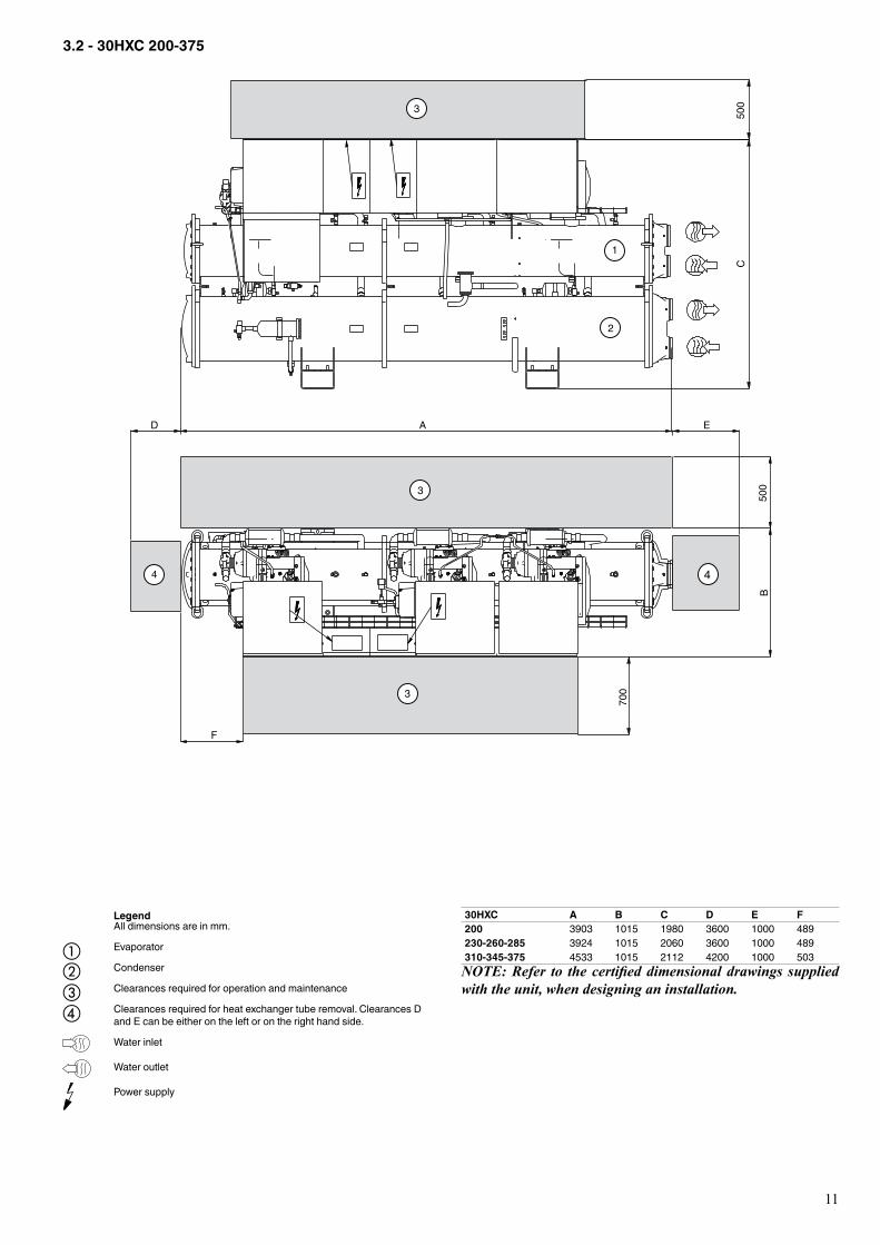
3.2 - 30HXC 200-375
30HXC A B C D E F200 3903 1015 1980 3600 1000 489230-260-285 3924 1015 2060 3600 1000 489310-345-375 4533 1015 2112 4200 1000 503NOTE: Refer to the certified dimensional drawings supplied with the unit, when designing an installation.
4
2
E
500
B
3
A
C
D
7003
4
5003
F
1
Legend Alldimensionsareinmm.
Evaporator
Condenser
Clearances required for operation and maintenance
Clearancesrequiredforheatexchangertuberemoval.ClearancesDandEcanbeeitherontheleftorontherighthandside.
Water inlet
Water outlet
Power supply
abcd
12
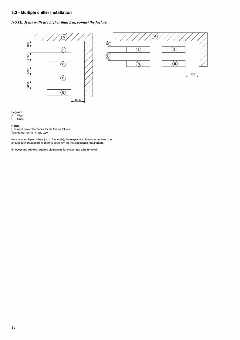
3.3 - Multiple chiller installation
NOTE: If the walls are higher than 2 m, contact the factory.
LegendA WallB Units
NotesUnitmusthaveclearancesforairflowasfollows:Top: do not restrict in any way
Incaseofmultiplechillers(uptofourunits),therespectiveclearancebetweenthemshouldbeincreasedfrom1830to2000mmforthesidespacerequirement.
Ifnecessary,addtherequiredclearancesforevaporatortuberemoval.
2000
1830
2000
1830
2000
2000
1525
1525
A
B
B
B
B
B B
B B
A
13
4 - PHYSICAL AND ELECTRICAL DATA - STANDARD 50HZ APPLICATION
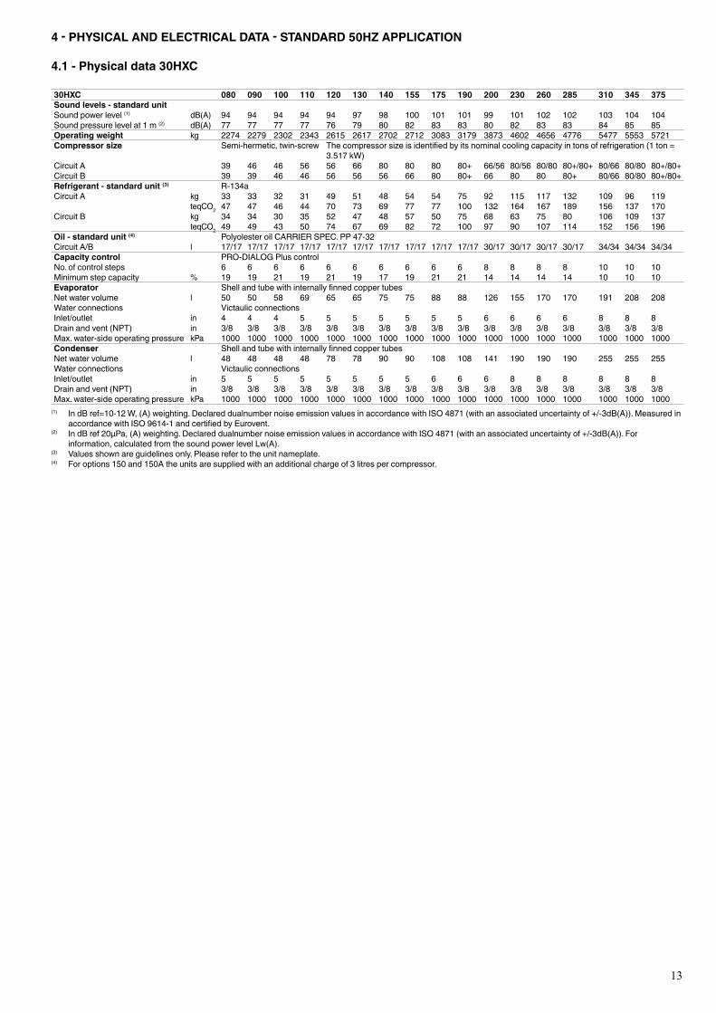
4.1 - Physical data 30HXC
30HXC 080 090 100 110 120 130 140 155 175 190 200 230 260 285 310 345 375Sound levels - standard unitSound power level (1) dB(A) 94 94 94 94 94 97 98 100 101 101 99 101 102 102 103 104 104Sound pressure level at 1 m (2) dB(A) 77 77 77 77 76 79 80 82 83 83 80 82 83 83 84 85 85Operating weight kg 2274 2279 2302 2343 2615 2617 2702 2712 3083 3179 3873 4602 4656 4776 5477 5553 5721Compressor size Semi-hermetic, twin-screw Thecompressorsizeisidentifiedbyitsnominalcoolingcapacityintonsofrefrigeration(1ton=
3.517kW)Circuit A 39 46 46 56 56 66 80 80 80 80+ 66/56 80/56 80/80 80+/80+ 80/66 80/80 80+/80+Circuit B 39 39 46 46 56 56 56 66 80 80+ 66 80 80 80+ 80/66 80/80 80+/80+Refrigerant - standard unit (3) R-134aCircuit A kg 33 33 32 31 49 51 48 54 54 75 92 115 117 132 109 96 119
teqCO2 47 47 46 44 70 73 69 77 77 100 132 164 167 189 156 137 170Circuit B kg 34 34 30 35 52 47 48 57 50 75 68 63 75 80 106 109 137
teqCO2 49 49 43 50 74 67 69 82 72 100 97 90 107 114 152 156 196Oil - standard unit (4) PolyolesteroilCARRIERSPEC.PP47-32Circuit A/B l 17/17 17/17 17/17 17/17 17/17 17/17 17/17 17/17 17/17 17/17 30/17 30/17 30/17 30/17 34/34 34/34 34/34Capacity control PRO-DIALOGPluscontrolNo.ofcontrolsteps 6 6 6 6 6 6 6 6 6 6 8 8 8 8 10 10 10Minimum step capacity % 19 19 21 19 21 19 17 19 21 21 14 14 14 14 10 10 10Evaporator ShellandtubewithinternallyfinnedcoppertubesNet water volume l 50 50 58 69 65 65 75 75 88 88 126 155 170 170 191 208 208Water connections Victaulic connectionsInlet/outlet in 4 4 4 5 5 5 5 5 5 5 6 6 6 6 8 8 8Drainandvent(NPT) in 3/8 3/8 3/8 3/8 3/8 3/8 3/8 3/8 3/8 3/8 3/8 3/8 3/8 3/8 3/8 3/8 3/8Max.water-sideoperatingpressure kPa 1000 1000 1000 1000 1000 1000 1000 1000 1000 1000 1000 1000 1000 1000 1000 1000 1000Condenser ShellandtubewithinternallyfinnedcoppertubesNet water volume l 48 48 48 48 78 78 90 90 108 108 141 190 190 190 255 255 255Water connections Victaulic connectionsInlet/outlet in 5 5 5 5 5 5 5 5 6 6 6 8 8 8 8 8 8Drainandvent(NPT) in 3/8 3/8 3/8 3/8 3/8 3/8 3/8 3/8 3/8 3/8 3/8 3/8 3/8 3/8 3/8 3/8 3/8Max.water-sideoperatingpressure kPa 1000 1000 1000 1000 1000 1000 1000 1000 1000 1000 1000 1000 1000 1000 1000 1000 1000
(1) IndBref=10-12W,(A)weighting.DeclareddualnumbernoiseemissionvaluesinaccordancewithISO4871(withanassociateduncertaintyof+/-3dB(A)).MeasuredinaccordancewithISO9614-1andcertifiedbyEurovent.
(2) IndBref20µPa,(A)weighting.DeclareddualnumbernoiseemissionvaluesinaccordancewithISO4871(withanassociateduncertaintyof+/-3dB(A)).Forinformation,calculatedfromthesoundpowerlevelLw(A).
(3) Valuesshownareguidelinesonly.Pleaserefertotheunitnameplate.(4) Foroptions150and150Atheunitsaresuppliedwithanadditionalchargeof3litrespercompressor.
14
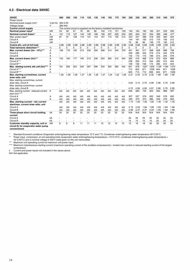
4.2 - Electrical data 30HXC
30HXC 080 090 100 110 120 130 140 155 175 190 200 230 260 285 310 345 375Power circuitNominalpowersupply(Un)* V-ph-Hz 400-3-50Voltage range V 360-440Control circuit supply The control circuit is supplied via the factory-installed transformerNominal power input* kW 53 62 67 76 80 89 102 112 121 129 140 164 192 195 221 250 263Nominal current drawn* A 101 115 127 143 149 168 190 207 226 234 255 294 337 354 399 448 477Max.powerinput** kW 87 97 108 119 131 144 161 175 192 212 223 257 288 318 350 384 424Circuit A kW - - - - - - - - - - 144 161 192 212 175 192 212Circuit B kW - - - - - - - - - - 79 96 96 106 175 192 212Cosine phi, unit at full load 0.88 0.88 0.88 0.88 0.89 0.88 0.88 0.89 0.89 0.89 0.88 0.89 0.89 0.89 0.89 0.89 0.89Total harmonic distortion*** % 0 0 0 0 0 0 0 0 0 0 0 0 0 0 0 0 0Max. current drawn (Un - 10%)*** A 158 176 195 215 235 259 289 314 344 379 401 461 517 568 628 688 758Circuit A A - - - - - - - - - - 259 289 344 379 314 344 379Circuit B A - - - - - - - - - - 142 172 172 189 314 344 379Max. current drawn (Un)*** A 143 160 177 195 213 236 263 285 312 344 365 419 468 516 570 624 688Circuit A*** A - - - - - - - - - - 236 263 312 344 285 312 344Circuit B*** A - - - - - - - - - - 129 156 156 172 285 312 344Max. starting current, std. unit (Un)**** A 181 206 223 249 267 298 333 355 382 442 841 978 1027 1200 1129 1184 1373Circuit A**** A - - - - - - - - - - 712 822 871 1028 844 871 1028Circuit B**** A - - - - - - - - - - 605 715 715 856 844 871 1028Max. starting current/max. current draw ratio, unit
1.26 1.28 1.26 1.27 1.25 1.26 1.27 1.24 1.22 1.28 2.31 2.33 2.19 2.32 1.98 1.89 1.99
Max.startingcurrent/max.currentdraw ratio, circuit A - - - - - - - - - - 3.02 3.13 2.79 2.99 2.96 2.79 2.99Max.startingcurrent/max.currentdraw ratio, circuit B - - - - - - - - - 4.70 4.58 4.58 4.97 2.96 2.79 2.99Max.startingcurrent-reducedcurrentstart(Un)****
A std. std. std. std. std. std. std. std. std. std. 636 683 732 824 834 889 997
Circuit A A std. std. std. std. std. std. std. std. std. std. 507 527 576 652 549 576 652Circuit B A std. std. std. std. std. std. std. std. std. std. 330 370 370 385 549 576 652Max. starting current - red. current start/max. current draw ratio, unit
std. std. std. std. std. std. std. std. std. std. 1.74 1.63 1.56 1.60 1.46 1.42 1.45
Circuit A std. std. std. std. std. std. std. std. std. std. 2.15 2.00 1.84 1.89 1.93 1.84 1.98Circuit B std. std. std. std. std. std. std. std. std. std. 2.56 2.37 2.37 2.24 1.93 1.84 1.89Three-phase short circuit holding current
kA 25 25 25 25 25 25 25 25 25 25 N/A N/A N/A N/A N/A N/A N/A
Circuit A kA - - - - - - - - - - 25 25 25 25 25 25 25Circuit B kA - - - - - - - - - - 15 15 15 15 25 25 25Customer standby capacity, unit or circuit B, for evaporator water pump connections†
kW 8 8 8 11 11 11 15 15 15 15 15 18 18 30 30 30 30
* StandardEuroventconditions:Evaporatorentering/leavingwatertemperature12°Cand7°C.Condenserentering/leavingwatertemperature30°C/35°C.** Powerinput,compressor,atunitoperatinglimits(evaporatorwaterentering/leavingtemperature=15°C/10°C,condenserentering/leavingwatertemperature=
45°C/50°C)andanominalvoltageof400V(datagivenontheunitnameplate).*** Maximumunitoperatingcurrentatmaximumunitpowerinput.**** Maximum instantaneous starting current (maximum operating current of the smallest compressor(s) + locked rotor current or reduced starting current of the largest
compressor)† Currentandpowerinputsnotincludedinthevaluesabove.N/ANotapplicable.
15
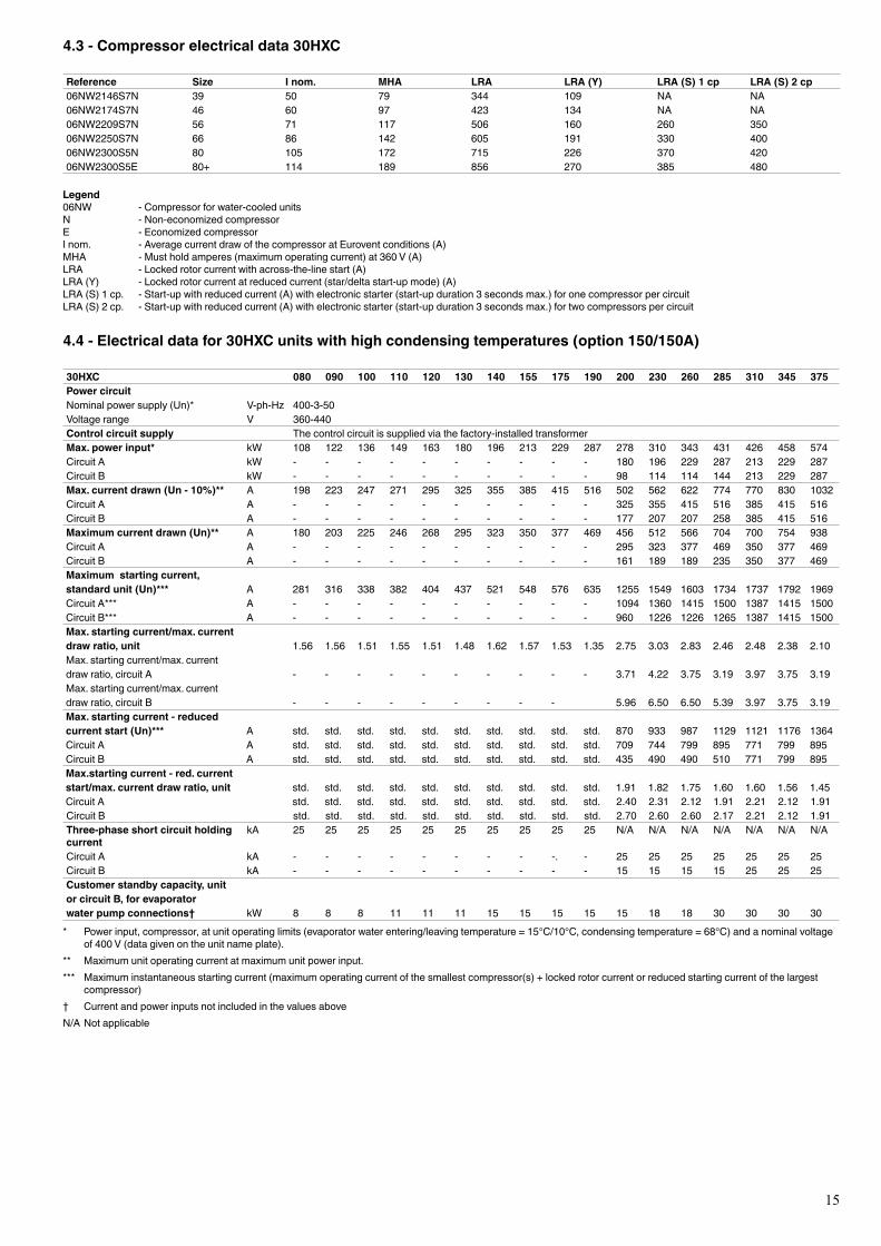
4.3 - Compressor electrical data 30HXC
Reference Size I nom. MHA LRA LRA (Y) LRA (S) 1 cp LRA (S) 2 cp06NW2146S7N 39 50 79 344 109 NA NA06NW2174S7N 46 60 97 423 134 NA NA06NW2209S7N 56 71 117 506 160 260 350 06NW2250S7N 66 86 142 605 191 330 40006NW2300S5N 80 105 172 715 226 370 42006NW2300S5E 80+ 114 189 856 270 385 480
Legend06NW - Compressor for water-cooled unitsN - Non-economized compressorE - Economized compressorInom. -AveragecurrentdrawofthecompressoratEuroventconditions(A)MHA - Must hold amperes (maximum operating current) at 360 V (A)LRA -Lockedrotorcurrentwithacross-the-linestart(A)LRA(Y) -Lockedrotorcurrentatreducedcurrent(star/deltastart-upmode)(A)LRA(S)1cp. -Start-upwithreducedcurrent(A)withelectronicstarter(start-upduration3secondsmax.)foronecompressorpercircuitLRA(S)2cp. -Start-upwithreducedcurrent(A)withelectronicstarter(start-upduration3secondsmax.)fortwocompressorspercircuit
4.4 - Electrical data for 30HXC units with high condensing temperatures (option 150/150A)
30HXC 080 090 100 110 120 130 140 155 175 190 200 230 260 285 310 345 375Power circuitNominalpowersupply(Un)* V-ph-Hz 400-3-50Voltage range V 360-440Control circuit supply The control circuit is supplied via the factory-installed transformerMax. power input* kW 108 122 136 149 163 180 196 213 229 287 278 310 343 431 426 458 574Circuit A kW - - - - - - - - - - 180 196 229 287 213 229 287Circuit B kW - - - - - - - - - - 98 114 114 144 213 229 287Max. current drawn (Un - 10%)** A 198 223 247 271 295 325 355 385 415 516 502 562 622 774 770 830 1032Circuit A A - - - - - - - - - - 325 355 415 516 385 415 516Circuit B A - - - - - - - - - - 177 207 207 258 385 415 516Maximum current drawn (Un)** A 180 203 225 246 268 295 323 350 377 469 456 512 566 704 700 754 938Circuit A A - - - - - - - - - - 295 323 377 469 350 377 469Circuit B A - - - - - - - - - - 161 189 189 235 350 377 469Maximum starting current, standard unit (Un)*** A 281 316 338 382 404 437 521 548 576 635 1255 1549 1603 1734 1737 1792 1969Circuit A*** A - - - - - - - - - - 1094 1360 1415 1500 1387 1415 1500Circuit B*** A - - - - - - - - - - 960 1226 1226 1265 1387 1415 1500Max. starting current/max. current draw ratio, unit 1.56 1.56 1.51 1.55 1.51 1.48 1.62 1.57 1.53 1.35 2.75 3.03 2.83 2.46 2.48 2.38 2.10Max.startingcurrent/max.currentdraw ratio, circuit A - - - - - - - - - - 3.71 4.22 3.75 3.19 3.97 3.75 3.19Max.startingcurrent/max.currentdraw ratio, circuit B - - - - - - - - - 5.96 6.50 6.50 5.39 3.97 3.75 3.19Max. starting current - reduced current start (Un)*** A std. std. std. std. std. std. std. std. std. std. 870 933 987 1129 1121 1176 1364Circuit A A std. std. std. std. std. std. std. std. std. std. 709 744 799 895 771 799 895Circuit B A std. std. std. std. std. std. std. std. std. std. 435 490 490 510 771 799 895Max.starting current - red. current start/max. current draw ratio, unit std. std. std. std. std. std. std. std. std. std. 1.91 1.82 1.75 1.60 1.60 1.56 1.45Circuit A std. std. std. std. std. std. std. std. std. std. 2.40 2.31 2.12 1.91 2.21 2.12 1.91Circuit B std. std. std. std. std. std. std. std. std. std. 2.70 2.60 2.60 2.17 2.21 2.12 1.91Three-phase short circuit holding current
kA 25 25 25 25 25 25 25 25 25 25 N/A N/A N/A N/A N/A N/A N/A
Circuit A kA - - - - - - - - -. - 25 25 25 25 25 25 25Circuit B kA - - - - - - - - - - 15 15 15 15 25 25 25Customer standby capacity, unit or circuit B, for evaporator water pump connections† kW 8 8 8 11 11 11 15 15 15 15 15 18 18 30 30 30 30* Powerinput,compressor,atunitoperatinglimits(evaporatorwaterentering/leavingtemperature=15°C/10°C,condensingtemperature=68°C)andanominalvoltage
of400V(datagivenontheunitnameplate).** Maximumunitoperatingcurrentatmaximumunitpowerinput.*** Maximum instantaneous starting current (maximum operating current of the smallest compressor(s) + locked rotor current or reduced starting current of the largest
compressor)† CurrentandpowerinputsnotincludedinthevaluesaboveN/ANotapplicable

16
The 30HXC 080-375 units for high condensing temperatures are directly derived from the standard models. Their application range is the same as that of the standard units, but permits operation at condenser leaving water temperatures up to 63°C. The PRO-DIALOG control offers all the advantages of the standard units, plus control of the condenser leaving water temperature.
The main modifications are: • Use of high lift compressors (example: 06NA2300S5N
instead of 06NW 2300S5N). • Modification of electrical components to operate with
compressors for high condensing temperatures. • Modification of heat exchangers to meet pressure code
requirements (if necessary).
Option 150These units are designed for traditional applications for water-cooled units, but for higher condender leaving water temperatures than 50°C.
Like the standard units they are equipped with condenser entering and leaving water sensors.
It is possible to control the machine at the condenser water outlet, requiring a factory configuration change and the use of a heating/cooling inlet reversing device.
Option 150AThese units are designed for water-to-water heat pumps.
They are factory configured as heat pumps (heating/cooling control as a function of the remote reversing device). The condenser incorporates thermal insulation that is identical to that of the evaporator.
Technical informationAll information is identical to that of the standard 30HXC units, except for the following paragraphs.
SelectionThere are no nominal conditions for this unit type. The selection is made using the current electronic catalogue.
DimensionsThese are identical to those of the standard 30HXC units. The only difference is in the diameter of the incoming field wiring connection, described in the chapter “Recommended selection”. Refer to the dimensional drawings for these units, before proceeding with the wiring.
CompressorSee table in chapter 4.5.
Options and accessoriesAll options available for the standard 30HXC units are compatible, except low-temperature option 5 for the evaporator available in the special unit.
ATTENTION: If units have two different operating modes - one with high condensing temperature and the other with low condensing temperature - and the transition is made with the unit in operation, the temperature must not vary by more than 3K per minute. In cases where this is not possible, it is recommended to go through a unit start/stop switch (remote start/stop available for standard units).
4.5 - Compressor electrical data 30HXC + option 150/150A
Reference Size I nom. MHA LRA LRA (Y) LRA (S) 1 cp. LRA (S) 2 cp.06NA2146S7N 39 72 99 605 191 NA NA06NA2174S7N 46 87 124 715 226 NA NA06NA2209S7N 56 103 148 856 270 330 48006NA2250S7N 66 124 177 960 303 435 57506NA2300S5N 80 149 207 1226 387 490 61006NA2300S5E 80+ 174 258 1265 400 510 660
Legend06NA - Compressor for air-cooled unitsN - Non-economized compressorE - Economized compressorInom. -AveragecurrentdrawofthecompressoratEuroventconditions(A)MHA - Must hold amperes (maximum operating current) at 360 V (A)LRA -Lockedrotorcurrentwithacross-the-linestart(A)LRA(Y) -Lockedrotorcurrentatreducedcurrent(star/deltastart-upmode)(A)LRA(S)1cp. -Start-upwithreducedcurrent(A)withelectronicstarter(start-upduration3secondsmax.)foronecompressorpercircuitLRA(S)2cp. -Start-upwithreducedcurrent(A)withelectronicstarter(start-upduration3secondsmax.)fortwocompressorspercircuit
17
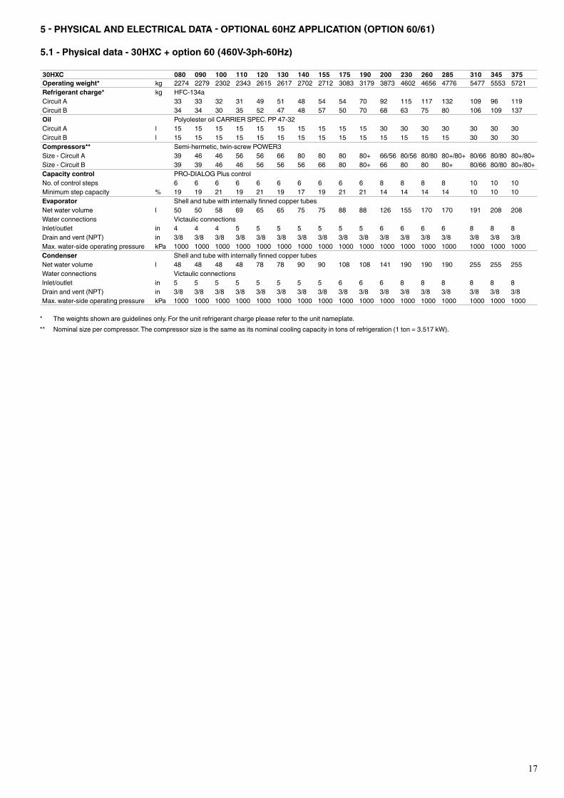
5 - PHYSICAL AND ELECTRICAL DATA - OPTIONAL 60HZ APPLICATION (OPTION 60/61)
5.1 - Physical data - 30HXC + option 60 (460V-3ph-60Hz)
30HXC 080 090 100 110 120 130 140 155 175 190 200 230 260 285 310 345 375Operating weight* kg 2274 2279 2302 2343 2615 2617 2702 2712 3083 3179 3873 4602 4656 4776 5477 5553 5721Refrigerant charge* kg HFC-134aCircuit A 33 33 32 31 49 51 48 54 54 70 92 115 117 132 109 96 119Circuit B 34 34 30 35 52 47 48 57 50 70 68 63 75 80 106 109 137Oil PolyolesteroilCARRIERSPEC.PP47-32Circuit A l 15 15 15 15 15 15 15 15 15 15 30 30 30 30 30 30 30Circuit B l 15 15 15 15 15 15 15 15 15 15 15 15 15 15 30 30 30Compressors** Semi-hermetic, twin-screw POWER3Size - Circuit A 39 46 46 56 56 66 80 80 80 80+ 66/56 80/56 80/80 80+/80+ 80/66 80/80 80+/80+Size - Circuit B 39 39 46 46 56 56 56 66 80 80+ 66 80 80 80+ 80/66 80/80 80+/80+Capacity control PRO-DIALOGPluscontrolNo.ofcontrolsteps 6 6 6 6 6 6 6 6 6 6 8 8 8 8 10 10 10Minimum step capacity % 19 19 21 19 21 19 17 19 21 21 14 14 14 14 10 10 10Evaporator ShellandtubewithinternallyfinnedcoppertubesNet water volume l 50 50 58 69 65 65 75 75 88 88 126 155 170 170 191 208 208Water connections Victaulic connectionsInlet/outlet in 4 4 4 5 5 5 5 5 5 5 6 6 6 6 8 8 8Drainandvent(NPT) in 3/8 3/8 3/8 3/8 3/8 3/8 3/8 3/8 3/8 3/8 3/8 3/8 3/8 3/8 3/8 3/8 3/8Max.water-sideoperatingpressure kPa 1000 1000 1000 1000 1000 1000 1000 1000 1000 1000 1000 1000 1000 1000 1000 1000 1000Condenser ShellandtubewithinternallyfinnedcoppertubesNet water volume l 48 48 48 48 78 78 90 90 108 108 141 190 190 190 255 255 255Water connections Victaulic connectionsInlet/outlet in 5 5 5 5 5 5 5 5 6 6 6 8 8 8 8 8 8Drainandvent(NPT) in 3/8 3/8 3/8 3/8 3/8 3/8 3/8 3/8 3/8 3/8 3/8 3/8 3/8 3/8 3/8 3/8 3/8Max.water-sideoperatingpressure kPa 1000 1000 1000 1000 1000 1000 1000 1000 1000 1000 1000 1000 1000 1000 1000 1000 1000
* Theweightsshownareguidelinesonly.Fortheunitrefrigerantchargepleaserefertotheunitnameplate.** Nominalsizepercompressor.Thecompressorsizeisthesameasitsnominalcoolingcapacityintonsofrefrigeration(1ton=3.517kW).
18
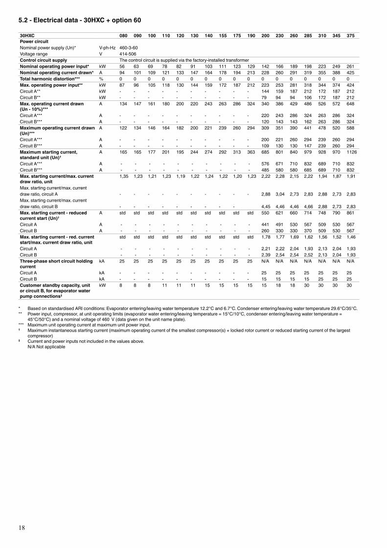
5.2 - Electrical data - 30HXC + option 60
30HXC 080 090 100 110 120 130 140 155 175 190 200 230 260 285 310 345 375Power circuitNominalpowersupply(Un)* V-ph-Hz 460-3-60Voltage range V 414-506Control circuit supply The control circuit is supplied via the factory-installed transformerNominal operating power input* kW 56 63 69 78 82 91 103 111 123 129 142 166 189 198 223 249 261Nominal operating current drawn* A 94 101 109 121 133 147 164 178 194 213 228 260 291 319 355 388 425Total harmonic distortion*** % 0 0 0 0 0 0 0 0 0 0 0 0 0 0 0 0 0Max. operating power input** kW 87 96 105 118 130 144 159 172 187 212 223 253 281 318 344 374 424Circuit A** kW - - - - - - - - - - 144 159 187 212 172 187 212Circuit B** kW - - - - - - - - - - 79 94 94 106 172 187 212Max. operating current drawn (Un - 10%)***
A 134 147 161 180 200 220 243 263 286 324 340 386 429 486 526 572 648
Circuit A*** A - - - - - - - - - - 220 243 286 324 263 286 324Circuit B*** A - - - - - - - - - - 120 143 143 162 263 286 324Maximum operating current drawn (Un)***
A 122 134 146 164 182 200 221 239 260 294 309 351 390 441 478 520 588
Circuit A*** A - - - - - - - - - - 200 221 260 294 239 260 294Circuit B*** A - - - - - - - - - - 109 130 130 147 239 260 294Maximum starting current, standard unit (Un)†
A 165 165 177 201 195 244 274 292 313 363 685 801 840 979 928 970 1126
Circuit A*** A - - - - - - - - - - 576 671 710 832 689 710 832Circuit B*** A - - - - - - - - - - 485 580 580 685 689 710 832Max. starting current/max. current draw ratio, unit
1,35 1,23 1,21 1,23 1,19 1,22 1,24 1,22 1,20 1,23 2,22 2,28 2,15 2,22 1,94 1,87 1,91
Max.startingcurrent/max.currentdraw ratio, circuit A - - - - - - - - - - 2,88 3,04 2,73 2,83 2,88 2,73 2,83Max.startingcurrent/max.currentdraw ratio, circuit B - - - - - - - - - 4,45 4,46 4,46 4,66 2,88 2,73 2,83Max. starting current - reduced current start (Un)†
A std std std std std std std std std std 550 621 660 714 748 790 861
Circuit A A - - - - - - - - - - 441 491 530 567 509 530 567Circuit B A - - - - - - - - - - 260 330 330 370 509 530 567Max. starting current - red. current start/max. current draw ratio, unit
std std std std std std std std std std 1,78 1,77 1,69 1,62 1,56 1,52 1,46
Circuit A - - - - - - - - - - 2,21 2,22 2,04 1,93 2,13 2,04 1,93Circuit B - - - - - - - - - - 2,39 2,54 2,54 2,52 2,13 2,04 1,93Three-phase short circuit holding current
kA 25 25 25 25 25 25 25 25 25 25 N/A N/A N/A N/A N/A N/A N/A
Circuit A kA - - - - - - - - - - 25 25 25 25 25 25 25Circuit B kA - - - - - - - - - - 15 15 15 15 25 25 25Customer standby capacity, unit or circuit B, for evaporator water pump connections‡
kW 8 8 8 11 11 11 15 15 15 15 15 18 18 30 30 30 30
* BasedonstandardisedARIconditions:Evaporatorentering/leavingwatertemperature12.2°Cand6.7°C.Condenserentering/leavingwatertemperature29.6°C/35°C.** Powerinput,compressor,atunitoperatinglimits(evaporatorwaterentering/leavingtemperature=15°C/10°C,condenserentering/leavingwatertemperature=
45°C/50°C)andanominalvoltageof460V(datagivenontheunitnameplate).*** Maximumunitoperatingcurrentatmaximumunitpowerinput.† Maximum instantaneous starting current (maximum operating current of the smallest compressor(s) + locked rotor current or reduced starting current of the largest
compressor)‡ Currentandpowerinputsnotincludedinthevaluesabove. N/ANotapplicable
19
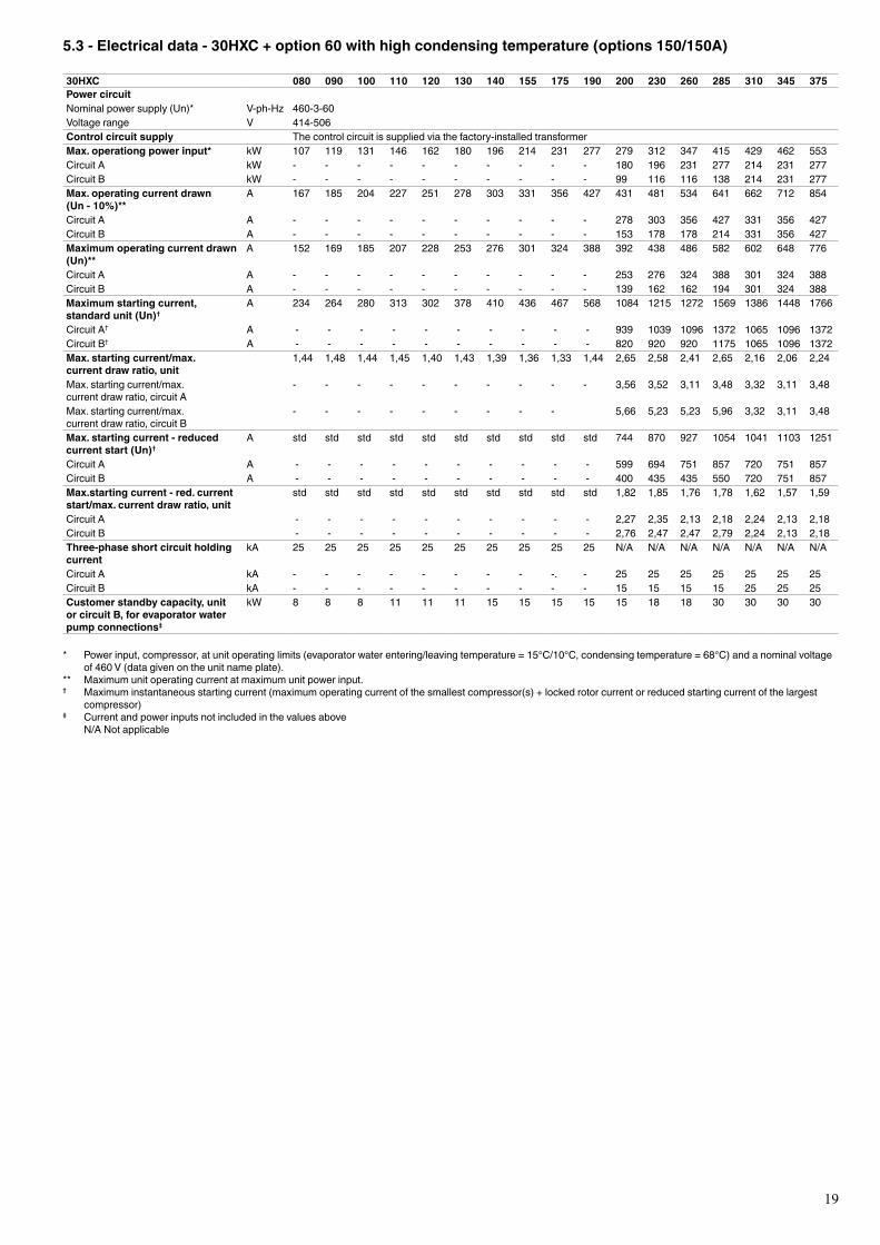
5.3 - Electrical data - 30HXC + option 60 with high condensing temperature (options 150/150A)
30HXC 080 090 100 110 120 130 140 155 175 190 200 230 260 285 310 345 375Power circuitNominalpowersupply(Un)* V-ph-Hz 460-3-60Voltage range V 414-506Control circuit supply The control circuit is supplied via the factory-installed transformerMax. operationg power input* kW 107 119 131 146 162 180 196 214 231 277 279 312 347 415 429 462 553Circuit A kW - - - - - - - - - - 180 196 231 277 214 231 277Circuit B kW - - - - - - - - - - 99 116 116 138 214 231 277Max. operating current drawn (Un - 10%)**
A 167 185 204 227 251 278 303 331 356 427 431 481 534 641 662 712 854
Circuit A A - - - - - - - - - - 278 303 356 427 331 356 427Circuit B A - - - - - - - - - - 153 178 178 214 331 356 427Maximum operating current drawn (Un)**
A 152 169 185 207 228 253 276 301 324 388 392 438 486 582 602 648 776
Circuit A A - - - - - - - - - - 253 276 324 388 301 324 388Circuit B A - - - - - - - - - - 139 162 162 194 301 324 388Maximum starting current, standard unit (Un)†
A 234 264 280 313 302 378 410 436 467 568 1084 1215 1272 1569 1386 1448 1766
Circuit A† A - - - - - - - - - - 939 1039 1096 1372 1065 1096 1372Circuit B† A - - - - - - - - - - 820 920 920 1175 1065 1096 1372Max. starting current/max. current draw ratio, unit
1,44 1,48 1,44 1,45 1,40 1,43 1,39 1,36 1,33 1,44 2,65 2,58 2,41 2,65 2,16 2,06 2,24
Max.startingcurrent/max.current draw ratio, circuit A
- - - - - - - - - - 3,56 3,52 3,11 3,48 3,32 3,11 3,48
Max.startingcurrent/max.current draw ratio, circuit B
- - - - - - - - - 5,66 5,23 5,23 5,96 3,32 3,11 3,48
Max. starting current - reduced current start (Un)†
A std std std std std std std std std std 744 870 927 1054 1041 1103 1251
Circuit A A - - - - - - - - - - 599 694 751 857 720 751 857Circuit B A - - - - - - - - - - 400 435 435 550 720 751 857Max.starting current - red. current start/max. current draw ratio, unit
std std std std std std std std std std 1,82 1,85 1,76 1,78 1,62 1,57 1,59
Circuit A - - - - - - - - - - 2,27 2,35 2,13 2,18 2,24 2,13 2,18Circuit B - - - - - - - - - - 2,76 2,47 2,47 2,79 2,24 2,13 2,18Three-phase short circuit holding current
kA 25 25 25 25 25 25 25 25 25 25 N/A N/A N/A N/A N/A N/A N/A
Circuit A kA - - - - - - - - -. - 25 25 25 25 25 25 25Circuit B kA - - - - - - - - - - 15 15 15 15 25 25 25Customer standby capacity, unit or circuit B, for evaporator water pump connections‡
kW 8 8 8 11 11 11 15 15 15 15 15 18 18 30 30 30 30
* Powerinput,compressor,atunitoperatinglimits(evaporatorwaterentering/leavingtemperature=15°C/10°C,condensingtemperature=68°C)andanominalvoltageof460V(datagivenontheunitnameplate).
** Maximumunitoperatingcurrentatmaximumunitpowerinput.† Maximum instantaneous starting current (maximum operating current of the smallest compressor(s) + locked rotor current or reduced starting current of the largest
compressor)‡ Currentandpowerinputsnotincludedinthevaluesabove N/ANotapplicable

20
5.4 - Physical data - 30HXC + option 61 (380V-3ph-60Hz)
30HXC 080 090 100 110 120 130 140 155 175 190 200 230 260 285 310 345 375Operating weight* kg 2274 2279 2302 2343 2615 2617 2702 2712 3083 3179 3873 4602 4656 4776 5477 5553 5721Refrigerant charge* kg HFC-134aCircuit A 33 33 32 31 49 51 48 54 54 70 92 115 117 132 109 96 119Circuit B 34 34 30 35 52 47 48 57 50 70 58 63 75 80 106 109 137Oil PolyolesteroilCARRIERSPEC.PP47-32Circuit A l 15 15 15 15 15 15 15 15 15 15 30 30 30 30 30 30 30Circuit B l 15 15 15 15 15 15 15 15 15 15 15 15 15 15 30 30 30Compressors** Semi-hermetic, twin-screw POWER3Size - Circuit A 39 46 46 56 56 66 80 80 80 80+ 66/56 80/56 80/80 80+/80+ 80/66 80/80 80+/80+Size - Circuit B 39 39 46 46 56 56 56 66 80 80+ 66 80 80 80+ 80/66 80/80 80+/80+Capacity control PRO-DIALOGPluscontrolNo.ofcontrolsteps 6 6 6 6 6 6 6 6 6 6 8 8 8 8 10 10 10Minimum step capacity % 19 19 21 19 21 19 17 19 21 21 14 14 14 14 10 10 10Evaporator ShellandtubewithinternallyfinnedcoppertubesNet water volume l 50 50 58 69 65 65 75 75 88 88 126 155 170 170 191 208 208Water connections Victaulic connectionsInlet/outlet in 4 4 4 5 5 5 5 5 5 5 6 6 6 6 8 8 8Drainandvent(NPT) in 3/8 3/8 3/8 3/8 3/8 3/8 3/8 3/8 3/8 3/8 3/8 3/8 3/8 3/8 3/8 3/8 3/8Max.water-sideoperatingpressure kPa 1000 1000 1000 1000 1000 1000 1000 1000 1000 1000 1000 1000 1000 1000 1000 1000 1000Condenser ShellandtubewithinternallyfinnedcoppertubesNet water volume l 48 48 48 48 78 78 90 90 108 108 141 190 190 190 255 255 255Water connections Victaulic connectionsInlet/outlet in 5 5 5 5 5 5 5 5 6 6 6 8 8 8 8 8 8Drainandvent(NPT) in 3/8 3/8 3/8 3/8 3/8 3/8 3/8 3/8 3/8 3/8 3/8 3/8 3/8 3/8 3/8 3/8 3/8Max.water-sideoperatingpressure kPa 1000 1000 1000 1000 1000 1000 1000 1000 1000 1000 1000 1000 1000 1000 1000 1000 1000
* Theweightsshownareguidelinesonly.Fortheunitrefrigerantchargepleaserefertotheunitnameplate.** Nominalsizepercompressor.Thecompressorsizeisthesameasitsnominalcoolingcapacityintonsofrefrigeration(1ton=3.517kW).
21
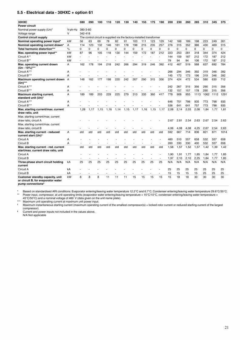
5.5 - Electrical data - 30HXC + option 61
30HXC 080 090 100 110 120 130 140 155 175 190 200 230 260 285 310 345 375Power circuitNominalpowersupply(Un)* V-ph-Hz 380-3-60Voltage range V 342-418Control circuit supply The control circuit is supplied via the factory-installed transformerNominal operating power input* kW 56 63 69 78 82 91 103 111 123 129 142 166 189 198 223 249 261Nominal operating current drawn* A 114 123 132 146 161 178 198 215 235 257 276 315 352 386 430 469 515Total harmonic distortion*** % 0 0 0 0 0 0 0 0 0 0 0 0 0 0 0 0 0Max. operating power input** kW 87 96 105 118 130 144 159 172 187 212 223 253 281 318 344 374 424Circuit A** kW - - - - - - - - - - 144 159 187 212 172 187 212Circuit B** kW - - - - - - - - - - 79 94 94 106 172 187 212Max. operating current drawn (Un - 10%)***
A 162 178 194 218 242 266 294 319 246 392 412 467 519 588 637 692 784
Circuit A*** A - - - - - - - - - - 266 294 346 392 319 346 392Circuit B*** A - - - - - - - - - - 145 173 173 196 319 346 392Maximum operating current drawn (Un)***
A 148 162 177 198 220 242 267 290 315 356 374 424 472 534 580 630 712
Circuit A*** A - - - - - - - - - - 242 267 315 356 290 315 356Circuit B*** A - - - - - - - - - - 132 157 157 178 290 315 356Maximum starting current, standard unit (Un)†
A 189 189 203 229 225 279 313 335 360 417 778 908 955 1113 1062 1112 1291
Circuit A*** A - - - - - - - - - - 646 751 798 935 773 798 935Circuit B*** A - - - - - - - - - - 536 641 641 757 773 798 935Max. starting current/max. current draw ratio, unit
1,28 1,17 1,15 1,16 1,14 1,15 1,17 1,16 1,15 1,17 2,08 2,14 2,03 2,08 1,84 1,77 1,81
Max.startingcurrent/max.currentdraw ratio, circuit A - - - - - - - - - - 2.67 2.81 2.54 2.63 2.67 2.54 2.63Max.startingcurrent/max.currentdraw ratio, circuit B - - - - - - - - - 4,06 4,08 4,08 4,25 2,67 2,54 2,63Max. starting current - reduced current start (Un)†
A std std std std std std std std std std 592 667 714 836 821 871 1014
Circuit A A - - - - - - - - - - 460 510 557 658 532 557 658Circuit B A - - - - - - - - - - 260 330 330 400 532 557 658Max. starting current - red. current start/max. current draw ratio, unit
std std std std std std std std std std 1,58 1,57 1,52 1,57 1,42 1,39 1,42
Circuit A - - - - - - - - - - 1,90 1,91 1,77 1,85 1,84 1,77 1,85Circuit B - - - - - - - - - - 1,97 2,10 2,10 2,25 1,84 1,77 1,85Three-phase short circuit holding current
kA 25 25 25 25 25 25 25 25 25 25 N/A N/A N/A N/A N/A N/A N/A
Circuit A kA - - - - - - - - - - 25 25 25 25 25 25 25Circuit B kA - - - - - - - - - - 15 15 15 15 25 25 25Customer standby capacity, unit or circuit B, for evaporator water pump connections‡
kW 8 8 8 11 11 11 15 15 15 15 15 18 18 30 30 30 30
* BasedonstandardisedARIconditions:Evaporatorentering/leavingwatertemperature12.2°Cand6.7°C.Condenserentering/leavingwatertemperature29.6°C/35°C.** Powerinput,compressor,atunitoperatinglimits(evaporatorwaterentering/leavingtemperature=15°C/10°C,condenserentering/leavingwatertemperature=
45°C/50°C)andanominalvoltageof460V(datagivenontheunitnameplate).*** Maximumunitoperatingcurrentatmaximumunitpowerinput.† Maximum instantaneous starting current (maximum operating current of the smallest compressor(s) + locked rotor current or reduced starting current of the largest
compressor)‡ Currentandpowerinputsnotincludedinthevaluesabove. N/ANotapplicable
22
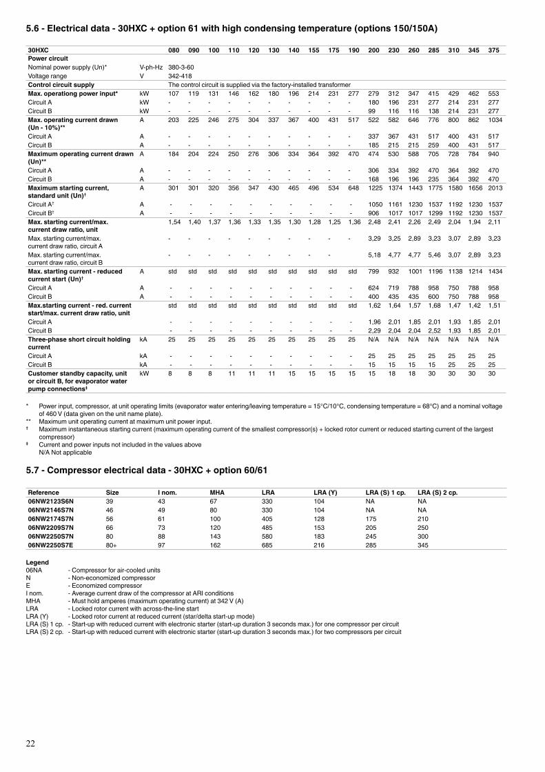
5.6 - Electrical data - 30HXC + option 61 with high condensing temperature (options 150/150A)
30HXC 080 090 100 110 120 130 140 155 175 190 200 230 260 285 310 345 375Power circuitNominalpowersupply(Un)* V-ph-Hz 380-3-60Voltage range V 342-418Control circuit supply The control circuit is supplied via the factory-installed transformerMax. operationg power input* kW 107 119 131 146 162 180 196 214 231 277 279 312 347 415 429 462 553Circuit A kW - - - - - - - - - - 180 196 231 277 214 231 277Circuit B kW - - - - - - - - - - 99 116 116 138 214 231 277Max. operating current drawn (Un - 10%)**
A 203 225 246 275 304 337 367 400 431 517 522 582 646 776 800 862 1034
Circuit A A - - - - - - - - - - 337 367 431 517 400 431 517Circuit B A - - - - - - - - - - 185 215 215 259 400 431 517Maximum operating current drawn (Un)**
A 184 204 224 250 276 306 334 364 392 470 474 530 588 705 728 784 940
Circuit A A - - - - - - - - - - 306 334 392 470 364 392 470Circuit B A - - - - - - - - - - 168 196 196 235 364 392 470Maximum starting current, standard unit (Un)†
A 301 301 320 356 347 430 465 496 534 648 1225 1374 1443 1775 1580 1656 2013
Circuit A† A - - - - - - - - - - 1050 1161 1230 1537 1192 1230 1537Circuit B† A - - - - - - - - - - 906 1017 1017 1299 1192 1230 1537Max. starting current/max. current draw ratio, unit
1,54 1,40 1,37 1,36 1,33 1,35 1,30 1,28 1,25 1,36 2,48 2,41 2,26 2,49 2,04 1,94 2,11
Max.startingcurrent/max.current draw ratio, circuit A
- - - - - - - - - - 3,29 3,25 2,89 3,23 3,07 2,89 3,23
Max.startingcurrent/max.current draw ratio, circuit B
- - - - - - - - - 5,18 4,77 4,77 5,46 3,07 2,89 3,23
Max. starting current - reduced current start (Un)†
A std std std std std std std std std std 799 932 1001 1196 1138 1214 1434
Circuit A A - - - - - - - - - - 624 719 788 958 750 788 958Circuit B A - - - - - - - - - - 400 435 435 600 750 788 958Max.starting current - red. current start/max. current draw ratio, unit
std std std std std std std std std std 1,62 1,64 1,57 1,68 1,47 1,42 1,51
Circuit A - - - - - - - - - - 1,96 2,01 1,85 2,01 1,93 1,85 2,01Circuit B - - - - - - - - - - 2,29 2,04 2,04 2,52 1,93 1,85 2,01Three-phase short circuit holding current
kA 25 25 25 25 25 25 25 25 25 25 N/A N/A N/A N/A N/A N/A N/A
Circuit A kA - - - - - - - - - - 25 25 25 25 25 25 25Circuit B kA - - - - - - - - - - 15 15 15 15 25 25 25Customer standby capacity, unit or circuit B, for evaporator water pump connections‡
kW 8 8 8 11 11 11 15 15 15 15 15 18 18 30 30 30 30
* Powerinput,compressor,atunitoperatinglimits(evaporatorwaterentering/leavingtemperature=15°C/10°C,condensingtemperature=68°C)andanominalvoltageof460V(datagivenontheunitnameplate).
** Maximumunitoperatingcurrentatmaximumunitpowerinput.† Maximum instantaneous starting current (maximum operating current of the smallest compressor(s) + locked rotor current or reduced starting current of the largest
compressor)‡ Currentandpowerinputsnotincludedinthevaluesabove N/ANotapplicable
5.7 - Compressor electrical data - 30HXC + option 60/61
Reference Size I nom. MHA LRA LRA (Y) LRA (S) 1 cp. LRA (S) 2 cp.06NW2123S6N 39 43 67 330 104 NA NA06NW2146S7N 46 49 80 330 104 NA NA06NW2174S7N 56 61 100 405 128 175 21006NW2209S7N 66 73 120 485 153 205 25006NW2250S7N 80 88 143 580 183 245 30006NW2250S7E 80+ 97 162 685 216 285 345
Legend06NA - Compressor for air-cooled unitsN - Non-economized compressorE - Economized compressorInom. -AveragecurrentdrawofthecompressoratARIconditionsMHA - Must hold amperes (maximum operating current) at 342 V (A)LRA -Lockedrotorcurrentwithacross-the-linestartLRA(Y) -Lockedrotorcurrentatreducedcurrent(star/deltastart-upmode)LRA(S)1cp. -Start-upwithreducedcurrentwithelectronicstarter(start-upduration3secondsmax.)foronecompressorpercircuitLRA(S)2cp. -Start-upwithreducedcurrentwithelectronicstarter(start-upduration3secondsmax.)fortwocompressorspercircuit

23
5.8 - Compressor electrical data - 30HXC + option 60/61 + option 150/150A
Reference Size I nom. MHA LRA LRA (Y) LRA (S) 1 cp. LRA (S) 2 cp.06NA2123W6N 39 62 84 485 153 NA NA06NA2146W7N 46 73 102 580 183 NA NA06NA2174W7N 56 89 125 685 216 245 34506NA2209W7N 66 107 153 820 259 290 41006NA2250W7N 80 127 178 920 291 320 46006NA2250W7E 80+ 148 214 1175 371 405 535
Legend06NA - Compressor for air-cooled unitsN - Non-economized compressorE - Economized compressorInom. -AveragecurrentdrawofthecompressoratARIconditionsMHA - Must hold amperes (maximum operating current) at 342 V (A)LRA -Lockedrotorcurrentwithacross-the-linestartLRA(Y) -Lockedrotorcurrentatreducedcurrent(star/deltastart-upmode)LRA(S)1cp. -Start-upwithreducedcurrentwithelectronicstarter(start-upduration3secondsmax.)foronecompressorpercircuitLRA(S)2cp. -Start-upwithreducedcurrentwithelectronicstarter(start-upduration3secondsmax.)fortwocompressorspercircuit
6 - UNIT CHARACTERISTICS FOR 30HXC UNITS WITH VERY LOW TEMPERATURE OPTION (OPTION 6 - OUT OF CE MARKING)
The 30HXC units with the very low temperature option are directly derived from the 30HXC models equipped with the high condensing temperature option (option 150). Unit sizes available with the very low temperature option are the following: 30HXC 090, 110, 130, 155, 175, 200, 230, 260, 310, 345.
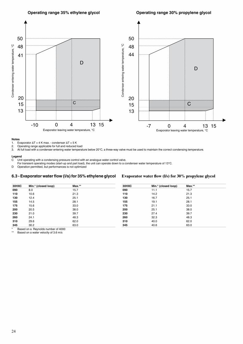
Their application range allows the production of glycol/water solution down to -10°C with ethylene glycol at 35% (by weight) or down to -7°C with propylene glycol at 30% (by weight). The precision of these amounts is critical for correct unit operation.
In addition to the ones already listed for the high condensing temperature option (see chapter 4.4) the main modifications are: • the evaporator is equipped with reinforced thermal 38 mm
insulation, • the electronic expansion valves are changed, • the use of a wide-band oil differential sensor.
All technical data is the same as for the 30HXC units with option 150 except for the following chapters:
6.1 - Options and accessories
The options available for the 30HXC units equipped with the very low temperature option are as follows: 20, 22, 60, 61, 84, 84D, 84R, 92, 104A, 107, 107A, 152, 193, 194, 197, 199.
6.2 - Operating range, 30HXC units with very low temperature option
30HXC evaporator with 35% ethylene glycol °C Minimum MaximumEvaporator entering water temperature -7.2 21Evaporator leaving water temperature -10 1530HXC evaporator with 30% polypropylene glycolEvaporator entering water temperature -4.2 21Evaporator leaving water temperature -7 1530HXC condenserCondenser entering water temperature 20 50Condenser leaving water temperature 25 55Outdoor air temperature 6 40
For very low temperature applications the anti-freeze solution is critical for correct unit operation. The following amounts (by weight) are required:
Evaporator leaving water, °C Ethylene glycol, % Propylene glycol, %-6 25 27-7 28 30-8 30 NA-9 33 NA-10 35 NA
24
Operating range 35% ethylene glycol
Evaporator leaving water temperature, °C
Notes1. Evaporator∆T=4Kmax.-condenser∆T=5K2. Operatingrangeapplicableforfullandreducedload3. Atfullloadwithacondenserenteringwatertemperaturebelow20°C,athree-wayvalvemustbeusedtomaintainthecorrectcondensingtemperature.
LegendC Unitoperatingwithacondensingpressurecontrolwithananaloguewatercontrolvalve. Fortransientoperatingmodes(start-upandpartload),theunitcanoperatedowntoacondenserwatertemperatureof13°C.D Operationpermitted,butperformancesisnotoptimized
Con
dens
er e
nter
ing
wate
r tem
pera
ture
, °C
Con
dens
er e
nter
ing
wate
r tem
pera
ture
, °C
Evaporator leaving water temperature, °C
504844
201513
D
C
-7 0 4 13 15
Operating range 30% propylene glycol
6.3 - Evaporator water flow (l/s) for 35% ethylene glycol
30HXC Min.* (closed loop) Max.**090 8.0 15.7110 10.6 21.3130 12.4 25.1155 14.5 28.1175 15.6 33.0200 20.5 38.0230 21.0 39.7260 24.1 48.3310 29.6 62.0345 30.2 63.0* BasedonaReynoldsnumberof4000** Basedonawatervelocityof3.6m/s
Evaporator water flow (l/s) for 30% propylene glycol
30HXC Min.* (closed loop) Max.**090 11.1 15.7110 14.2 21.3130 16.7 25.1155 19.1 28.1175 21.1 33.0200 25.1 38.0230 27.4 39.7260 32.3 48.3310 40.0 62.0345 40.6 63.0
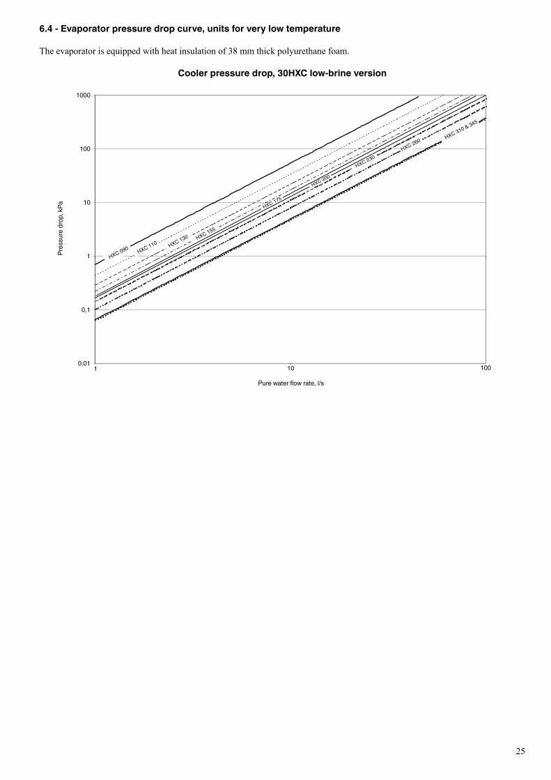
25
6.4 - Evaporator pressure drop curve, units for very low temperature
The evaporator is equipped with heat insulation of 38 mm thick polyurethane foam.
Cooler pressure drop, 30HXC low-brine version
Purewaterflowrate,l/s
Pres
sure
dro
p, k
Pa
0,01
0,1
1
10
100
1000
1 10 100
HXC 310 & 345
HXC 260
HXC 230
HXC 155
HXC 130
HXC 110
HXC 090
HXC 175
HXC 200
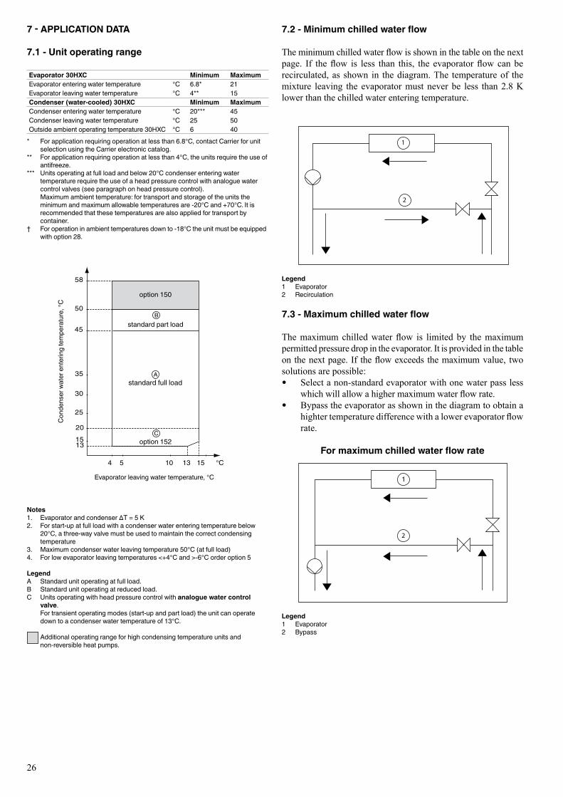
26
7 - APPLICATION DATA
7.1 - Unit operating range
Evaporator 30HXC Minimum MaximumEvaporator entering water temperature °C 6.8* 21Evaporator leaving water temperature °C 4** 15Condenser (water-cooled) 30HXC Minimum MaximumCondenser entering water temperature °C 20*** 45Condenser leaving water temperature °C 25 50Outsideambientoperatingtemperature30HXC °C 6 40* Forapplicationrequiringoperationatlessthan6.8°C,contactCarrierforunit
selectionusingtheCarrierelectroniccatalog.** For application requiring operation at less than 4°C, the units require the use of
antifreeze.*** Unitsoperatingatfullloadandbelow20°Ccondenserenteringwater
temperature require the use of a head pressure control with analogue water controlvalves(seeparagraphonheadpressurecontrol).
Maximumambienttemperature:fortransportandstorageoftheunitstheminimumandmaximumallowabletemperaturesare-20°Cand+70°C.Itisrecommendedthatthesetemperaturesarealsoappliedfortransportbycontainer.
† Foroperationinambienttemperaturesdownto-18°Ctheunitmustbeequippedwithoption28.
Notes1. Evaporatorandcondenser∆T=5K2. Forstart-upatfullloadwithacondenserwaterenteringtemperaturebelow
20°C,athree-wayvalvemustbeusedtomaintainthecorrectcondensingtemperature
3. Maximumcondenserwaterleavingtemperature50°C(atfullload)4. Forlowevaporatorleavingtemperatures<+4°Cand>-6°Corderoption5
LegendA Standardunitoperatingatfullload.B Standardunitoperatingatreducedload.C Unitsoperatingwithheadpressurecontrolwithanalogue water control
valve. For transient operating modes (start-up and part load) the unit can operate
downtoacondenserwatertemperatureof13°C.
Additional operating range for high condensing temperature units and non-reversibleheatpumps.
Evaporator leaving water temperature, °C
Con
dens
er w
ater
ent
erin
g te
mpe
ratu
re, °
C
standard full load
7.2 - Minimum chilled water flow
The minimum chilled water flow is shown in the table on the next page. If the flow is less than this, the evaporator flow can be recirculated, as shown in the diagram. The temperature of the mixture leaving the evaporator must never be less than 2.8 K lower than the chilled water entering temperature.
Legend1 Evaporator2 Recirculation
7.3 - Maximum chilled water flow
The maximum chilled water flow is limited by the maximum permitted pressure drop in the evaporator. It is provided in the table on the next page. If the flow exceeds the maximum value, two solutions are possible: • Select a non-standard evaporator with one water pass less
which will allow a higher maximum water flow rate. • Bypass the evaporator as shown in the diagram to obtain a
highter temperature difference with a lower evaporator flow rate.
For maximum chilled water flow rate
1
Legend1 Evaporator2 Bypass
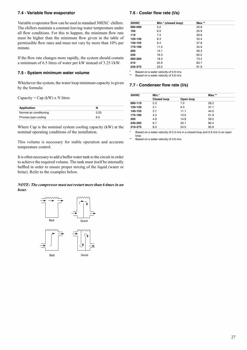
27
7.4 - Variable flow evaporator
Variable evaporator flow can be used in standard 30HXC chillers. The chillers maintain a constant leaving water temperature under all flow conditions. For this to happen, the minimum flow rate must be higher than the minimum flow given in the table of permissible flow rates and must not vary by more than 10% per minute.
If the flow rate changes more rapidly, the system should contain a minimum of 6.5 litres of water per kW instead of 3.25 l/kW.
7.5 - System minimum water volume
Whichever the system, the water loop minimum capacity is given by the formula: Capacity = Cap (kW) x N litres
Application NNormal air conditioning 3.25Process type cooling 6.5
Where Cap is the nominal system cooling capacity (kW) at the nominal operating conditions of the installation.
This volume is necessary for stable operation and accurate temperature control.
It is often necessary to add a buffer water tank to the circuit in order to achieve the required volume. The tank must itself be internally baffled in order to ensure proper mixing of the liquid (water or brine). Refer to the examples below.
7.6 - Cooler flow rate (l/s)
30HXC Min.* (closed loop) Max.**080-090 5.2 20.8100 6.5 25.9110 7.4 29.6120-130 8.3 33.4140-155 9.4 37.8175-190 11.5 45.9200 14.1 56.3230 16.3 65.2260-285 18.3 73.4310 20.9 83.7345-375 23.0 91.9* Basedonawatervelocityof0.9m/s.** Basedonawatervelocityof3.6m/s.
7.7 - Condenser flow rate (l/s)
30HXC Min.* Max.**Closed loop Open loop
080-110 2.3 7.0 28.2120-130 3.1 9.3 37.1140-155 3.7 11.1 44.5175-190 4.3 13.0 51.9200 4.9 14.8 59.2230-285 6.7 20.1 80.4310-375 8.0 24.0 95.9* Basedonawatervelocityof0.3m/sinaclosedloopand0.9m/sinanopen
loop.** Basedonawatervelocityof3.6m/s.
Bad
Bad
Good
Good
NOTE: The compressor must not restart more than 6 times in an hour.
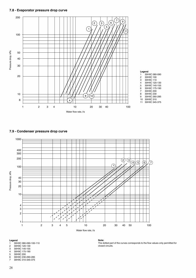
28
7.8 - Evaporator pressure drop curvePr
essu
re d
rop,
kPa
Waterflowrate,l/s
Legend1 30HXC080-0902 30HXC 1003 30HXC 1104 30HXC 120-1305 30HXC 140-1556 30HXC175-1907 30HXC2008 30HXC 2309 30HXC260-28510 30HXC 31011 30HXC345-375
7.9 - Condenser pressure drop curve
Pres
sure
dro
p, k
Pa
Waterflowrate,l/s
Note: Thedottedpartofthecurvescorrespondstotheflowvaluesonlypermittedforclosedcircuits.
Legend1 30HXC080-090-100-1102 30HXC 120-1303 30HXC 140-1554 30HXC175-1905 30HXC 2006 30HXC 230-260-2857 30HXC310-345-375
10
100
1 2 3 4 10 20 30 40
40
20
100
30
200
8
50
1
2 3
4
56
7
8
9
10
11
1
10
100
1000
1 2 3 4 5 10 20 30 40 50 100
234
20
3040
200
300400
1
2 34 5 6 7
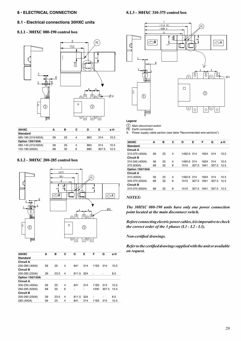
29
8.1.2 - 30HXC 200-285 control box
30HXC A B C D E ø HStandard 080-190(315/400A) 56 25 4 863 314 10.5Option 150/150A080-140 (315/400A) 56 25 4 863 314 10.5155-190(630A) 68 32 6 880 307.5 12.5
30HXC A B C D E F G ø HStandard Circuit A200-285 (400A) 56 25 4 841 314 1183 314 10.5Circuit B200-285 (250A) 39 23.5 4 811.5 324 - - 8.5Option 150/150ACircuit A200-230 (400A) 56 25 4 841 314 1183 314 10.5260-285 (630A) 68 32 6 - - 1200 307.5 12.5Circuit B200-260 (250A) 39 23.5 4 811.5 324 - - 8.5285 (400A) 56 25 4 841 314 1183 314 10.5
8.1.3 - 30HXC 310-375 control box
Legenda Main disconnect switchPE Earth connectionS Powersupplycablesection(seetable“Recommendedwiresections”).
30HXC A B C D E F G ø HStandard Circuit A310-375(400A) 56 25 4 1492.6 314 1824 314 10.5Circuit B310-345 (400A) 56 25 4 1492.6 314 1824 314 10.5375(630A) 68 32 6 1510 307.5 1841 307.5 12.5Option 150/150ACircuit A310 (400A) 56 25 4 1492.6 314 1824 314 10.5345-375(630A) 68 32 6 1510 307.5 1841 307.5 12.5Circuit B310-375(630A) 68 32 6 1510 307.5 1841 307.5 12.5
NOTES:
The 30HXC 080-190 units have only one power connection point located at the main disconnect switch.
Before connecting electric power cables, it is imperative to check the correct order of the 3 phases (L1 - L2 - L3).
Non-certified drawings.
Refer to the certified drawings supplied with the unit or available on request.
8 - ELECTRICAL CONNECTION
8.1 - Electrical connections 30HXC units
8.1.1 - 30HXC 080-190 control box
a
a
a
a
aa

30
8.2 - Power supply
The power supply must conform to the specification on the chiller nameplate. The supply voltage must be within the range specified in the electrical data table. For connections refer to the wiring diagrams.WARNING: Operation of the chiller with an improper supply voltage or excessive phase imbalance constitutes abuse which will invalidate the Carrier warranty. If the phase imbalance exceeds 2% for voltage, or 10% for current, contact your local electricity supply at once and ensure that the chiller is not switched on until corrective measures have been taken.
8.3 - Voltage phase imbalance (%)
100 x max. deviation from average voltage Average voltage
Example:On a 400 V - 3 ph - 50 Hz supply, the individual phase voltages were measured to be:
AB = 406 V; BC = 399 V; AC = 394 V
Average voltage = (406 + 399 + 394)/3 = 1199/3 = 399.7 say 400 V
Calculate the maximum deviation from the 400 V average:(AB) = 406 - 400 = 6(BC) = 400 - 399 = 1(CA) = 400 - 394 = 6
The maximum deviation from the average is 6 V. The greatest percentage deviation is:
100 x 6/400 = 1.5%
This is less than the permissible 2% and is therefore acceptable.
Motor
Electrical data notes for 30HXC units:• 30HXC080-190unitshaveasinglepowerconnectionpoint;30HXC200-375
unitshavetwoconnectionpoints.• Thecontrolboxincludesthefollowingstandardfeatures: - Starter and motor protection devices for each compressor - Control devices• Field connections: Allconnectionstothesystemandtheelectricalinstallationsmustbeinfull
accordancewithallapplicablecodes.• TheCarrier30HXCunitsaredesignedandbuilttoensureconformancewith
localcodes.TherecommendationsofEuropeanstandardEN60204-1(correspondstoIEC60204-1)(machinesafety-electricalmachinecomponents-part1:generalregulations)arespecificallytakenintoaccount,whendesigningtheelectricalequipment.
• Electrical reserves: CircuitBhasdisconnectswitchesandbranchsections,designedtosupplythe
evaporatorandcondenserpumppowerinput.
IMPORTANT:• GenerallytherecommendationsofIEC60364areacceptedascompliance
withtherequirementsoftheinstallationdirectives.ConformancewithEN60204-1isthebestmeansofensuringcompliancewiththeMachinesDirectiveand§1.5.1.
• AnnexBofEN60204-1describestheelectricalcharacteristicsusedfortheoperationofthemachines.
1. Theoperatingenvironmentforthe30HXCunitsisspecifiedbelow: a. Environment*-EnvironmentasclassifiedinIEC60364§3: - ambienttemperaturerange:+5°Cto+40°C,classAA4
- humidity range (non-condensing)*: 50% relative humidity at 40°C 90%relativehumidityat20°C - altitude:≤2000m - indoor installation* - presenceofwater:classAD2*(possibilityofwaterdroplets) - presenceofhardsolids,classAE2*(nosignificantdustpresent) - presenceofcorrosiveandpollutingsubstances,classAF1(negligible) - vibrationandshock,classAG2,AH2 b. Competenceofpersonnel,classBA4*(trainedpersonnel-IEC60364)2. Powersupplyfrequencyvariation:±2Hz.3. Theneutral(N)linemustnotbeconnecteddirectlytotheunit(ifnecessaryuse
atransformer).4. Overcurrentprotectionofthepowersupplyconductorsisnotprovidedwiththe
unit.5. Thefactory-installeddisconnectswitch(es)/circuitbreaker(s)is(are)ofatype
suitableforpowerinterruptioninaccordancewithEN60947(correspondstoIEC60947).
6. TheunitsaredesignedforconnectiontoTNnetworks(IEC60364).ForITnetworkstheearthconnectionmustnotbeatthenetworkearth.Providealocalearth, consult competent local organisations to complete the electrical installation.
NOTE: If particular aspects of an actual installation do not conform to the conditions described above, or if there are other conditions which should be considered, always contact your local Carrier representative.
* TheprotectionlevelrequiredtoconformtothisclassisIP21B(accordingtoreferencedocumentIEC60529).All30HXCunitsareprotectedtoIP23Candfulfilthisprotectioncondition.

31
8.4 - Recommended wire sections
Wire sizing is the responsibility of the installer, and depends on the characteristics and regulations applicable to each installation site. The following is only to be used as a guideline, and does not make Carrier in any way liable. After wire sizing has been completed, using the certified dimensional drawing, the installer must ensure easy connection and define any modifications necessary on site.
The connections provided as standard for the field-supplied power entry cables to the general disconnect/isolator switch are designed for the number and type of wires, listed in the table below.
The calculations are based on the maximum machine current (see electrical data tables).
For the design of 30HXC units installed inside the building, the following standardized installation methods are used, in accordance with IEC 60364, table 52C: • No.13: perforated horizontal cable conduit, • No. 41: closed conduit.
The calculation is based on PVC or XLPE insulated cables with copper or aluminium core. The maximum temperature is 40°C.
The given wire length limits the voltage drop to < 5%.
IMPORTANT: Before connection of the main power cables (L1 - L2 - L3) on the terminal block, it is imperative to check the correct order of the 3 phases before proceeding to the connection on then terminal block or the main disconnect/isolator switch.
8.4.1 - Field control wiring
IMPORTANT: Field connection of interface circuits may lead to safety risks: any control box modification must maintain equipment conformity with local regulations. Precautions must be taken to prevent accidental electrical contact between circuits supplied by different sources: • The routing selection and/or conductor insulation
characteristics must ensure dual electric insulation. • In case of accidental disconnection, conductor fixing
between different conductors and/or in the control box prevents any contact between the conductor ends and an active energised part.
Refer to the 30GX/HXC Pro-Dialog Plus Controls IOM and the certified wiring diagram supplied with the unit for the field control wirting of the following features: • Evaporator pump interlock (mandatory) • Remote on/off switch • Condenser flow switch (field-supplied) • Remote heat/cool switch • Demand limit external switch 1 • Remote dual setpoint • Alarm report by circuit • Evaporator pump control • Condenser pump control • Remote setpoint reset or outside air temperature sensor reset
(0-10 V)

32
8.4.2 - Selection table of minimum and maximum wire sections - 400 V-3 ph-50 Hz
30HXC Minimum wiresection (mm2)*
Wire type L (m) Maximum wiresection (mm2)*
Wire type L (m)
080 1 x 50 XLPECu 160 1 x 120 XLPEAl 205090 1 x 50 XLPECu 160 1 x 120 XLPEAl 205100 1x70 XLPECu 170 1 x 150 XLPEAl 210110 1x70 XLPECu 170 1 x 185 XLPEAl 220120 1x95 XLPECu 180 1 x 185 XLPEAl 220130 1x95 XLPECu 180 1 x 240 XLPEAl 225140 1 x 120 XLPECu 185 2x95 XLPEAl 195155 1 x 120 XLPECu 185 2 x 120 XLPEAl 205175 1 x 150 XLPECu 190 2 x 120 XLPEAl 205190 1 x 185 XLPECu 190 2 x 150 XLPEAl 210200 Circuit A 1x95 XLPECu 180 1 x 185 XLPEAl 220
1 x 120 XLPECu 225230 Circuit A 1x95 XLPECu 180 1 x 240 XLPEAl 225
1 x 150 XLPECu 230260 Circuit A 1 x 120 XLPECu 185 2 x 150 XLPEAl 265
1 x 240 XLPECu 235285 Circuit A 1 x 150 XLPECu 190 2 x 185 XLPEAl 270
2 x 120 XLPECu 280310 Circuit A 1 x 120 XLPECu 185 2 x 120 XLPEAl 255
2x95 XLPECu 270345 Circuit A 1 x 120 XLPECu 185 2 x 150 XLPEAl 265
2x95 XLPECu 270375 Circuit A 1 x 150 XLPECu 190 2 x 185 XLPEAl 270
2 x 120 XLPECu 280200 Circuit B 1 x 50 XLPECu 160 1 x 120 XLPEAl 205
1x70 XLPECu 205230 Circuit B 1x70 XLPECu 170 1 x 150 XLPEAl 210
1x95 XLPECu 215260 Circuit B 1x95 XLPECu 180 1 x 150 XLPEAl 210
1x95 XLPECu 215285 Circuit B 1x95 XLPECu 180 1 x 185 XLPEAl 220
1 x 120 XLPECu 225310 Circuit B 1 x 185 XLPECu 190 2 x 185 XLPEAl 270
1 x 240 XLPECu 235345 Circuit B 1 x 185 XLPECu 190 2 x 185 XLPEAl 270
2 x 120 XLPECu 280375 Circuit B 1 x 240 XLPECu 190 2 x 240 XLPEAl 280
2 x 150 XLPECu 290
* Powersupplywiresection(seediagrams/legendSinchapter‘Electricalconnection’).Thedisconnectswitchesareindicatedbya1.
8.4.3 - Selection table of minimum and maximum wire sections 400V-3ph-50Hz + option 150
30HXC Minimum wiresection (mm2)*
Wire type L (m) Maximum wiresection (mm2)*
Wire type L (m)
080 Opt. 150 1x70 XLPECu 170 1 x 150 XLPEAl 210090 Opt. 150 1x70 XLPECu 170 1 x 185 XLPEAl 220100 Opt. 150 1x95 XLPECu 180 1 x 240 XLPEAl 225110 Opt. 150 1x95 XLPECu 180 1 x 240 XLPEAl 225120 Opt. 150 1 x 120 XLPECu 185 2x95 XLPEAl 195130 Opt. 150 1 x 120 XLPECu 185 2 x 120 XLPEAl 205140 Opt. 150 1 x 150 XLPECu 190 2 x 120 XLPEAl 205155 Opt. 150 1 x 185 XLPECu 190 2 x 150 XLPEAl 210175 Opt. 150 1 x 185 XLPECu 190 2 x 150 XLPEAl 210190 Opt. 150 2x95 XLPECu 170 2 x 240 XLPEAl 225200 Opt. 150 Circuit A 1 x 120 XLPECu 185 2 x 150 XLPEAl 265
1 x 185 XLPECu 235230 Opt. 150 Circuit A 1 x 150 XLPECu 190 2 x 150 XLPEAl 265
1 x 240 XLPECu 235260 Opt. 150 Circuit A 1 x 185 XLPECu 190 2 x 240 XLPEAl 280
2 x 150 XLPECu 290285 Opt. 150 Circuit A 1 x 240 XLPECu 190 2 x 240 XLPECu 295310 Opt. 150 Circuit A 1 x 150 XLPECu 190 2 x 185 XLPEAl 270
2 x 120 XLPECu 280345 Opt. 150 Circuit A 1 x 185 XLPECu 190 2 x 240 XLPEAl 280
2 x 150 XLPECu 290375 Opt. 150 Circuit A 1 x 240 XLPECu 190 2 x 240 XLPECu 295200 Opt. 150 Circuit B 1x70 XLPECu 170 1 x 150 XLPEAl 210
1x95 XLPECu 215230 Opt. 150 Circuit B 1x70 XLPECu 170 1 x 185 XLPEAl 220
1 x 120 XLPECu 225260 Opt. 150 Circuit B 1x70 XLPECu 170 1 x 185 XLPEAl 220
1 x 120 XLPECu 225285 Opt. 150 Circuit B 1 x 120 XLPECu 185 2 x 150 XLPEAl 265
1 x 185 XLPECu 235310 Opt. 150 Circuit B 1 x 185 XLPECu 190 2 x 240 XLPEAl 280
2 x 150 XLPECu 290345 Opt. 150 Circuit B 1 x 240 XLPECu 190 2 x 240 XLPEAl 280
2 x 150 XLPECu 290375 Opt. 150 Circuit B 2x95 XLPECu 170 2 x 240 XLPECu 295* Powersupplywiresection(seediagrams/legendSinchapter‘Electricalconnection’).Thedisconnectswitchesareindicatedbya1.
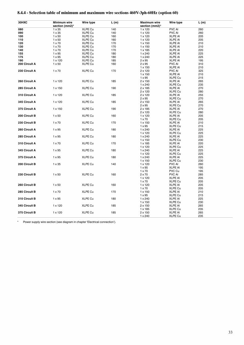
33
8.4.4 - Selection table of minimum and maximum wire sections 460V-3ph-60Hz (option 60)
30HXC Minimum wiresection (mm2)*
Wire type L (m) Maximum wiresection (mm2)*
Wire type L (m)
080 1 x 35 XLPECu 140 1 x 120 PVC Al 260090 1 x 35 XLPECu 140 1 x 120 PVC Al 260100 1 x 50 XLPECu 160 1 x 120 XLPEAl 205110 1 x 50 XLPECu 160 1 x 120 XLPEAl 205120 1x70 XLPECu 170 1 x 150 XLPEAl 210130 1x70 XLPECu 170 1 x 150 XLPEAl 210140 1x70 XLPECu 170 1 x 185 XLPEAl 220155 1x95 XLPECu 180 1 x 240 XLPEAl 225175 1x95 XLPECu 180 1 x 240 XLPEAl 225190 1 x 120 XLPECu 185 2x95 XLPEAl 195200 Circuit A 1 x 50 XLPECu 160 2x95 PVC Al 310
1 x 150 XLPEAl 210230 Circuit A 1x70 XLPECu 170 2 x 120 PVC Al 325
1 x 150 XLPEAl 2101x95 XLPECu 215
260 Circuit A 1 x 120 XLPECu 185 2 x 150 XLPEAl 2651 x 240 XLPECu 235
285 Circuit A 1 x 150 XLPECu 190 2 x 185 XLPEAl 2702 x 120 XLPECu 280
310 Circuit A 1 x 120 XLPECu 185 2 x 120 XLPEAl 2552x95 XLPECu 270
345 Circuit A 1 x 120 XLPECu 185 2 x 150 XLPEAl 2652x95 XLPECu 270
375 Circuit A 1 x 150 XLPECu 190 2 x 185 XLPEAl 2702 x 120 XLPECu 280
200 Circuit B 1 x 50 XLPECu 160 1 x 120 XLPEAl 2051x70 XLPECu 205
230 Circuit B 1x70 XLPECu 170 1 x 150 XLPEAl 2101x95 XLPECu 215
260 Circuit A 1x95 XLPECu 180 1 x 240 XLPEAl 2251 x 120 XLPECu 225
285 Circuit A 1x95 XLPECu 180 1 x 240 XLPEAl 2251 x 150 XLPECu 230
310 Circuit A 1x70 XLPECu 170 1 x 185 XLPEAl 2201 x 120 XLPECu 225
345 Circuit A 1x95 XLPECu 180 1 x 240 XLPEAl 2251 x 120 XLPECu 225
375 Circuit A 1x95 XLPECu 180 1 x 240 XLPEAl 2251 x 150 XLPECu 230
200 Circuit B 1 x 35 XLPECu 140 1 x 120 PVC Al 2601x95 XLPEAl 1951x70 PVC Cu 195
230 Circuit B 1 x 50 XLPECu 160 2x70 PVC Al 2851 x 120 XLPEAl 2051x70 XLPECu 205
260 Circuit B 1 x 50 XLPECu 160 1 x 120 XLPEAl 2051x70 XLPECu 205
285 Circuit B 1x70 XLPECu 170 1 x 150 XLPEAl 2101x95 XLPECu 215
310 Circuit B 1x95 XLPECu 180 1 x 240 XLPEAl 2251 x 150 XLPECu 230
345 Circuit B 1 x 120 XLPECu 185 2 x 150 XLPEAl 2651 x 185 XLPECu 235
375 Circuit B 1 x 120 XLPECu 185 2 x 150 XLPEAl 2651 x 240 XLPECu 235
* Powersupplywiresection(seediagraminchapter‘Electricalconnection’).

34
8.4.5 - Selection table of minimum and maximum wire sections 460V-3ph-60Hz + option 150/150A
30HXC Minimum wiresection (mm2)*
Wire type L (m) Maximum wiresection (mm2)*
Wire type L (m)
080 1 x 50 XLPECu 160 1 x 150 XLPEAl 210090 1x70 XLPECu 170 1 x 150 XLPEAl 210100 1x70 XLPECu 170 1 x 185 XLPEAl 220110 1x95 XLPECu 180 1 x 240 XLPEAl 225120 1x95 XLPECu 180 1 x 240 XLPEAl 225130 1 x 120 XLPECu 185 2x95 XLPEAl 195140 1 x 150 XLPECu 190 2 x 120 XLPEAl 205155 1 x 150 XLPECu 190 2 x 120 XLPEAl 205175 1 x 185 XLPECu 190 2 x 150 XLPEAl 210190 1 x 240 XLPECu 190 2 x 185 XLPEAl 210200 Circuit A 1x95 XLPECu 180 1 x 240 XLPEAl 225
1 x 150 XLPECu 230230 Circuit A 1 x 120 XLPECu 185 2 x 150 XLPEAl 265
1 x 185 XLPECu 235260 Circuit A 1 x 150 XLPECu 190 2 x 185 XLPEAl 270
1 x 240 XLPECu 235285 Circuit A 1 x 185 XLPECu 190 2 x 240 XLPEAl 280
2 x 150 XLPECu 290310 Circuit A 1 x 120 XLPECu 185 2 x 150 XLPEAl 265
1 x 240 XLPECu 235345 Circuit A 1 x 150 XLPECu 190 2 x 185 XLPEAl 270
1 x 240 XLPECu 235375 Circuit A 1 x 185 XLPECu 190 2 x 240 XLPEAl 280
2 x 150 XLPECu 290200 Circuit B 1 x 50 XLPECu 160 1 x 120 XLPEAl 205
1x95 XLPECu 215230 Circuit B 1x70 XLPECu 170 1 x 185 XLPEAl 220
1 x 120 XLPECu 225260 Circuit B 1x70 XLPECu 170 1 x 185 XLPEAl 220
1 x 120 XLPECu 225285 Circuit B 1x95 XLPECu 180 1 x 240 XLPEAl 225
1 x 150 XLPECu 230310 Circuit B 1 x 185 XLPECu 190 2 x 185 XLPEAl 270
2 x 120 XLPECu 280345 Circuit B 1 x 185 XLPECu 190 2 x 240 XLPEAl 280
2 x 150 XLPECu 290375 Circuit B 1 x 240 XLPECu 190 2 x 240 XLPECu 295
* Powersupplywiresection(seediagraminchapter‘Electricalconnection’).
8.4.6 - Selection table of minimum and maximum wire sections 380V-3ph-60Hz (option 61)
30HXC Minimum wiresection (mm2)*
Wire type L (m) Maximum wiresection (mm2)*
Wire type L (m)
080 1 x 50 XLPECu 160 1 x 120 XLPEAl 205090 2 x 50 XLPECu 160 1 x 120 XLPEAl 205100 1x70 XLPECu 170 1 x 150 XLPEAl 210110 1x70 XLPECu 170 1 x 150 XLPEAl 210120 1x70 XLPECu 170 1 x 185 XLPEAl 220130 1x95 XLPECu 180 1 x 240 XLPEAl 225140 1 x 120 XLPECu 185 1 x 240 XLPEAl 225155 1 x 120 XLPECu 185 2x95 XLPEAl 195175 1 x 120 XLPECu 185 2 x 120 XLPEAl 205190 1 x 150 XLPECu 190 2 x 120 XLPEAl 205200 Circuit A 1x70 XLPECu 170 1 x 185 XLPEAl 220
1 x 120 XLPECu 225230 Circuit A 1x95 XLPECu 180 1 x 240 XLPEAl 225
1 x 150 XLPECu 230260 Circuit A 1 x 120 XLPECu 185 2 x 120 XLPEAl 255
1 x 185 XLPECu 235285 Circuit A 1 x 120 XLPECu 185 2 x 150 XLPEAl 265
1 x 185 XLPECu 235310 Circuit A 1x95 XLPECu 180 1 x 240 XLPEAl 225
1 x 150 XLPECu 230345 Circuit A 1 x 120 XLPECu 185 2 x 120 XLPEAl 255
1 x 185 XLPECu 235375 Circuit A 1 x 120 XLPECu 185 2 x 150 XLPEAl 265
1 x 185 XLPECu 235200 Circuit B 1 x 50 XLPECu 160 1 x 120 XLPEAl 205
1x70 XLPECu 205230 Circuit B 1x70 XLPECu 170 1 x 150 XLPEAl 210
1x95 XLPECu 215260 Circuit B 1x70 XLPECu 170 1 x 150 XLPEAl 210
1x95 XLPECu 215285 Circuit B 1x70 XLPECu 170 1 x 185 XLPEAl 220
1 x 150 XLPECu 225310 Circuit B 1 x 150 XLPECu 190 2 x 150 XLPEAl 265
1 x 240 XLPECu 235345 Circuit B 1 x 150 XLPECu 190 2 x 185 XLPEAl 270
2 x 120 XLPECu 280375 Circuit B 1 x 185 XLPECu 190 2 x 185 XLPEAl 270
2 x 120 XLPECu 280
* Powersupplywiresection(seediagraminchapter‘Electricalconnection’).
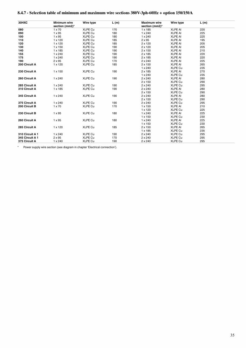
35
8.4.7 - Selection table of minimum and maximum wire sections 380V-3ph-60Hz + option 150/150A
30HXC Minimum wiresection (mm2)*
Wire type L (m) Maximum wiresection (mm2)*
Wire type L (m)
080 1x70 XLPECu 170 1 x 185 XLPEAl 220090 1x95 XLPECu 180 1 x 240 XLPEAl 225100 1x95 XLPECu 180 1 x 240 XLPEAl 225110 1 x 120 XLPECu 185 2x95 XLPEAl 195120 1 x 120 XLPECu 185 2 x 120 XLPEAl 205130 1 x 150 XLPECu 190 2 x 120 XLPEAl 205140 1 x 185 XLPECu 190 2 x 150 XLPEAl 210155 1 x 240 XLPECu 190 2 x 185 XLPEAl 220175 1 x 240 XLPECu 190 2 x 185 XLPEAl 220190 2x95 XLPECu 170 2 x 240 XLPEAl 225200 Circuit A 1 x 120 XLPECu 185 2 x 150 XLPEAl 265
1 x 240 XLPECu 235230 Circuit A 1 x 150 XLPECu 190 2 x 185 XLPEAl 270
1 x 240 XLPECu 235260 Circuit A 1 x 240 XLPECu 190 2 x 240 XLPEAl 280
2 x 150 XLPECu 290285 Circuit A 1 x 240 XLPECu 190 2 x 240 XLPECu 295310 Circuit A 1 x 185 XLPECu 190 2 x 240 XLPEAl 280
2 x 150 XLPECu 290345 Circuit A 1 x 240 XLPECu 190 2 x 240 XLPEAl 280
2 x 150 XLPECu 290375 Circuit A 1 x 240 XLPECu 190 2 x 240 XLPECu 295200 Circuit B 1x70 XLPECu 170 1 x 150 XLPEAl 210
1 x 120 XLPECu 225230 Circuit B 1x95 XLPECu 180 1 x 240 XLPEAl 225
1 x 150 XLPECu 230260 Circuit A 1x95 XLPECu 180 1 x 240 XLPEAl 225
1 x 150 XLPECu 230285 Circuit A 1 x 120 XLPECu 185 2 x 150 XLPEAl 265
1 x 185 XLPECu 235310 Circuit A 1 1 x 240 XLPECu 190 2 x 240 XLPECu 295345 Circuit A 1 2x95 XLPECu 170 2 x 240 XLPECu 295375 Circuit A 1 x 240 XLPECu 190 2 x 240 XLPECu 295
* Powersupplywiresection(seediagraminchapter‘Electricalconnection’).
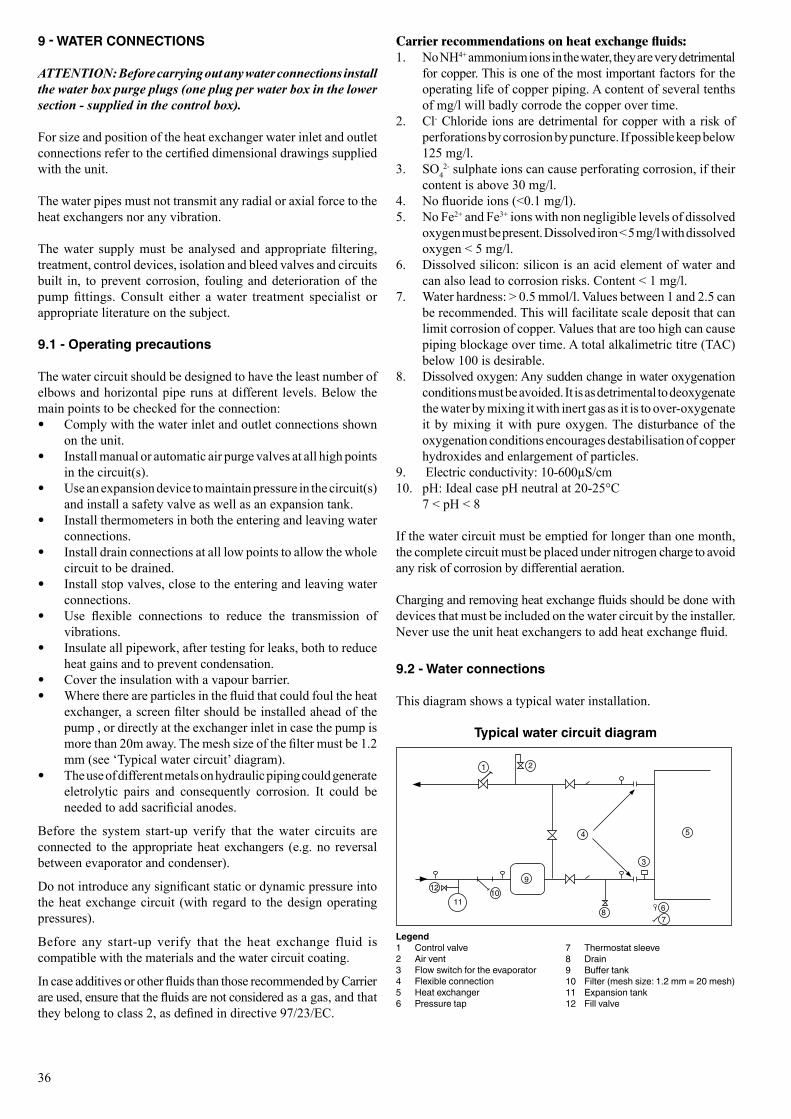
36
9 - WATER CONNECTIONS
ATTENTION: Before carrying out any water connections install the water box purge plugs (one plug per water box in the lower section - supplied in the control box).
For size and position of the heat exchanger water inlet and outlet connections refer to the certified dimensional drawings supplied with the unit.
The water pipes must not transmit any radial or axial force to the heat exchangers nor any vibration.
The water supply must be analysed and appropriate filtering, treatment, control devices, isolation and bleed valves and circuits built in, to prevent corrosion, fouling and deterioration of the pump fittings. Consult either a water treatment specialist or appropriate literature on the subject.
9.1 - Operating precautions
The water circuit should be designed to have the least number of elbows and horizontal pipe runs at different levels. Below the main points to be checked for the connection:
• Comply with the water inlet and outlet connections shown on the unit.
• Install manual or automatic air purge valves at all high points in the circuit(s).
• Use an expansion device to maintain pressure in the circuit(s) and install a safety valve as well as an expansion tank.
• Install thermometers in both the entering and leaving water connections.
• Install drain connections at all low points to allow the whole circuit to be drained.
• Install stop valves, close to the entering and leaving water connections.
• Use flexible connections to reduce the transmission of vibrations.
• Insulate all pipework, after testing for leaks, both to reduce heat gains and to prevent condensation.
• Cover the insulation with a vapour barrier. • Where there are particles in the fluid that could foul the heat
exchanger, a screen filter should be installed ahead of the pump , or directly at the exchanger inlet in case the pump is more than 20m away. The mesh size of the filter must be 1.2 mm (see ‘Typical water circuit’ diagram).
• The use of different metals on hydraulic piping could generate eletrolytic pairs and consequently corrosion. It could be needed to add sacrificial anodes.
Before the system start-up verify that the water circuits are connected to the appropriate heat exchangers (e.g. no reversal between evaporator and condenser).
Do not introduce any significant static or dynamic pressure into the heat exchange circuit (with regard to the design operating pressures).
Before any start-up verify that the heat exchange fluid is compatible with the materials and the water circuit coating.
In case additives or other fluids than those recommended by Carrier are used, ensure that the fluids are not considered as a gas, and that they belong to class 2, as defined in directive 97/23/EC.
Carrier recommendations on heat exchange fluids:1. No NH4+ ammonium ions in the water, they are very detrimental
for copper. This is one of the most important factors for the operating life of copper piping. A content of several tenths of mg/l will badly corrode the copper over time.
2. Cl- Chloride ions are detrimental for copper with a risk of perforations by corrosion by puncture. If possible keep below 125 mg/l.
3. SO42- sulphate ions can cause perforating corrosion, if their
content is above 30 mg/l.4. No fluoride ions (<0.1 mg/l).5. No Fe2+ and Fe3+ ions with non negligible levels of dissolved
oxygen must be present. Dissolved iron < 5 mg/l with dissolved oxygen < 5 mg/l.
6. Dissolved silicon: silicon is an acid element of water and can also lead to corrosion risks. Content < 1 mg/l.
7. Water hardness: > 0.5 mmol/l. Values between 1 and 2.5 can be recommended. This will facilitate scale deposit that can limit corrosion of copper. Values that are too high can cause piping blockage over time. A total alkalimetric titre (TAC) below 100 is desirable.
8. Dissolved oxygen: Any sudden change in water oxygenation conditions must be avoided. It is as detrimental to deoxygenate the water by mixing it with inert gas as it is to over-oxygenate it by mixing it with pure oxygen. The disturbance of the oxygenation conditions encourages destabilisation of copper hydroxides and enlargement of particles.
9. Electric conductivity: 10-600µS/cm10. pH: Ideal case pH neutral at 20-25°C 7 < pH < 8
If the water circuit must be emptied for longer than one month, the complete circuit must be placed under nitrogen charge to avoid any risk of corrosion by differential aeration.
Charging and removing heat exchange fluids should be done with devices that must be included on the water circuit by the installer. Never use the unit heat exchangers to add heat exchange fluid.
9.2 - Water connections
This diagram shows a typical water installation.
Typical water circuit diagram
Legend1 Control valve2 Air vent3 Flow switch for the evaporator4 Flexibleconnection5 Heat exchanger6 Pressure tap
1 2
3
4 5
67
8
910
11
12
7 Thermostatsleeve8 Drain9 Buffertank10 Filter(meshsize:1.2mm=20mesh)11 Expansion tank12 Fill valve
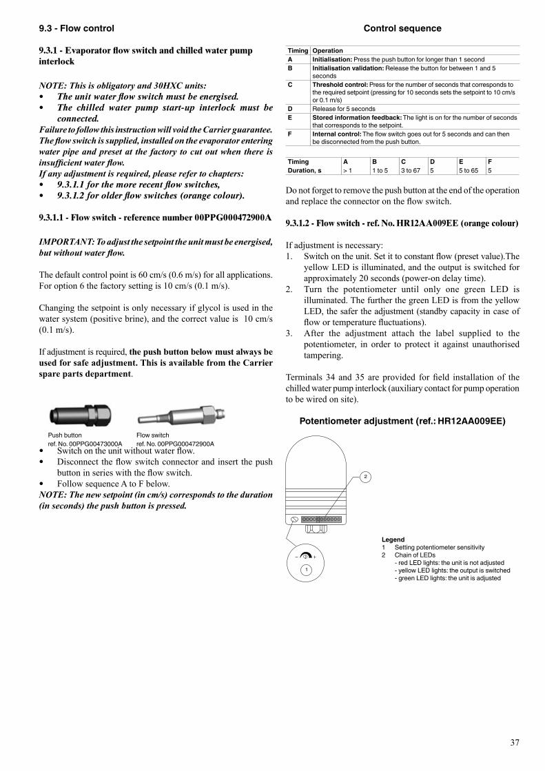
37
9.3 - Flow control
9.3.1 - Evaporator flow switch and chilled water pump interlock
NOTE: This is obligatory and 30HXC units: • The unit water flow switch must be energised. • The chilled water pump start-up interlock must be
connected.Failure to follow this instruction will void the Carrier guarantee.The flow switch is supplied, installed on the evaporator entering water pipe and preset at the factory to cut out when there is insufficient water flow.If any adjustment is required, please refer to chapters: • 9.3.1.1 for the more recent flow switches,• 9.3.1.2 for older flow switches (orange colour).
9.3.1.1 - Flow switch - reference number 00PPG000472900A
IMPORTANT: To adjust the setpoint the unit must be energised, but without water flow.
The default control point is 60 cm/s (0.6 m/s) for all applications. For option 6 the factory setting is 10 cm/s (0.1 m/s).
Changing the setpoint is only necessary if glycol is used in the water system (positive brine), and the correct value is 10 cm/s (0.1 m/s).
If adjustment is required, the push button below must always be used for safe adjustment. This is available from the Carrier spare parts department.
• Switch on the unit without water flow. • Disconnect the flow switch connector and insert the push
button in series with the flow switch. • Follow sequence A to F below.
NOTE: The new setpoint (in cm/s) corresponds to the duration (in seconds) the push button is pressed.
Control sequence
Timing OperationA Initialisation:Pressthepushbuttonforlongerthan1secondB Initialisation validation:Releasethebuttonforbetween1and5
secondsC Threshold control:Pressforthenumberofsecondsthatcorrespondsto
the required setpoint (pressing for 10 seconds sets the setpoint to 10 cm/s or0.1m/s)
D Release for 5 secondsE Stored information feedback:Thelightisonforthenumberofseconds
thatcorrespondstothesetpoint.F Internal control:Theflowswitchgoesoutfor5secondsandcanthen
bedisconnectedfromthepushbutton.
Timing A B C D E FDuration, s > 1 1 to 5 3to67 5 5 to 65 5
Do not forget to remove the push button at the end of the operation and replace the connector on the flow switch.
9.3.1.2 - Flow switch - ref. No. HR12AA009EE (orange colour)
If adjustment is necessary: 1. Switch on the unit. Set it to constant flow (preset value).The
yellow LED is illuminated, and the output is switched for approximately 20 seconds (power-on delay time).
2. Turn the potentiometer until only one green LED is illuminated. The further the green LED is from the yellow LED, the safer the adjustment (standby capacity in case of flow or temperature fluctuations).
3. After the adjustment attach the label supplied to the potentiometer, in order to protect it against unauthorised tampering.
Terminals 34 and 35 are provided for field installation of the chilled water pump interlock (auxiliary contact for pump operation to be wired on site).
Potentiometer adjustment (ref.: HR12AA009EE)
Legend1 Setting potentiometer sensitivity2 ChainofLEDs -redLEDlights:theunitisnotadjusted -yellowLEDlights:theoutputisswitched -greenLEDlights:theunitisadjusted
2
1
Pushbutton Flow switchref.No.00PPG00473000A ref.No.00PPG000472900A
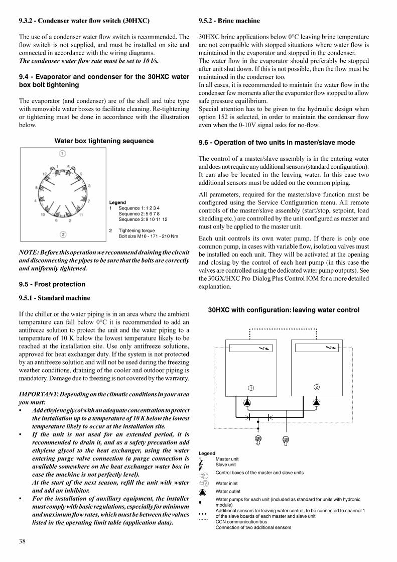
38
NOTE: Before this operation we recommend draining the circuit and disconnecting the pipes to be sure that the bolts are correctly and uniformly tightened.
9.5 - Frost protection
9.5.1 - Standard machine
If the chiller or the water piping is in an area where the ambient temperature can fall below 0°C it is recommended to add an antifreeze solution to protect the unit and the water piping to a temperature of 10 K below the lowest temperature likely to be reached at the installation site. Use only antifreeze solutions, approved for heat exchanger duty. If the system is not protected by an antifreeze solution and will not be used during the freezing weather conditions, draining of the cooler and outdoor piping is mandatory. Damage due to freezing is not covered by the warranty.
IMPORTANT: Depending on the climatic conditions in your area you must:• Add ethylene glycol with an adequate concentration to protect
the installation up to a temperature of 10 K below the lowest temperature likely to occur at the installation site.
• If the unit is not used for an extended period, it is recommended to drain it, and as a safety precaution add ethylene glycol to the heat exchanger, using the water entering purge valve connection (a purge connection is available somewhere on the heat exchanger water box in case the machine is not perfectly level).
At the start of the next season, refill the unit with water and add an inhibitor.
• For the installation of auxiliary equipment, the installer must comply with basic regulations, especially for minimum and maximum flow rates, which must be between the values listed in the operating limit table (application data).
9.5.2 - Brine machine
30HXC brine applications below 0°C leaving brine temperature are not compatible with stopped situations where water flow is maintained in the evaporator and stopped in the condenser.The water flow in the evaporator should preferably be stopped after unit shut down. If this is not possible, then the flow must be maintained in the condenser too. In all cases, it is recommended to maintain the water flow in the condenser few moments after the evaporator flow stopped to allow safe pressure equilibrium.Special attention has to be given to the hydraulic design when option 152 is selected, in order to maintain the condenser flow even when the 0-10V signal asks for no-flow.
9.6 - Operation of two units in master/slave mode
The control of a master/slave assembly is in the entering water and does not require any additional sensors (standard configuration). It can also be located in the leaving water. In this case two additional sensors must be added on the common piping.
All parameters, required for the master/slave function must be configured using the Service Configuration menu. All remote controls of the master/slave assembly (start/stop, setpoint, load shedding etc.) are controlled by the unit configured as master and must only be applied to the master unit.
Each unit controls its own water pump. If there is only one common pump, in cases with variable flow, isolation valves must be installed on each unit. They will be activated at the opening and closing by the control of each heat pump (in this case the valves are controlled using the dedicated water pump outputs). See the 30GX/HXC Pro-Dialog Plus Control IOM for a more detailed explanation.
30HXC with configuration: leaving water control
9.3.2 - Condenser water flow switch (30HXC)
The use of a condenser water flow switch is recommended. The flow switch is not supplied, and must be installed on site and connected in accordance with the wiring diagrams.The condenser water flow rate must be set to 10 l/s.
9.4 - Evaporator and condenser for the 30HXC water box bolt tightening
The evaporator (and condenser) are of the shell and tube type with removable water boxes to facilitate cleaning. Re-tightening or tightening must be done in accordance with the illustration below.
Water box tightening sequence
Legend1 Sequence 1: 1 2 3 4 Sequence2:5678 Sequence3:9101112
2 Tightening torque BoltsizeM16-171-210Nm
1 2
Legend1 Master unit2 Slave unit Controlboxesofthemasterandslaveunits
Water inlet Water outlet Water pumps for each unit (included as standard for units with hydronic
module) Additionalsensorsforleavingwatercontrol,tobeconnectedtochannel1
oftheslaveboardsofeachmasterandslaveunit CCNcommunicationbus Connection of two additional sensors
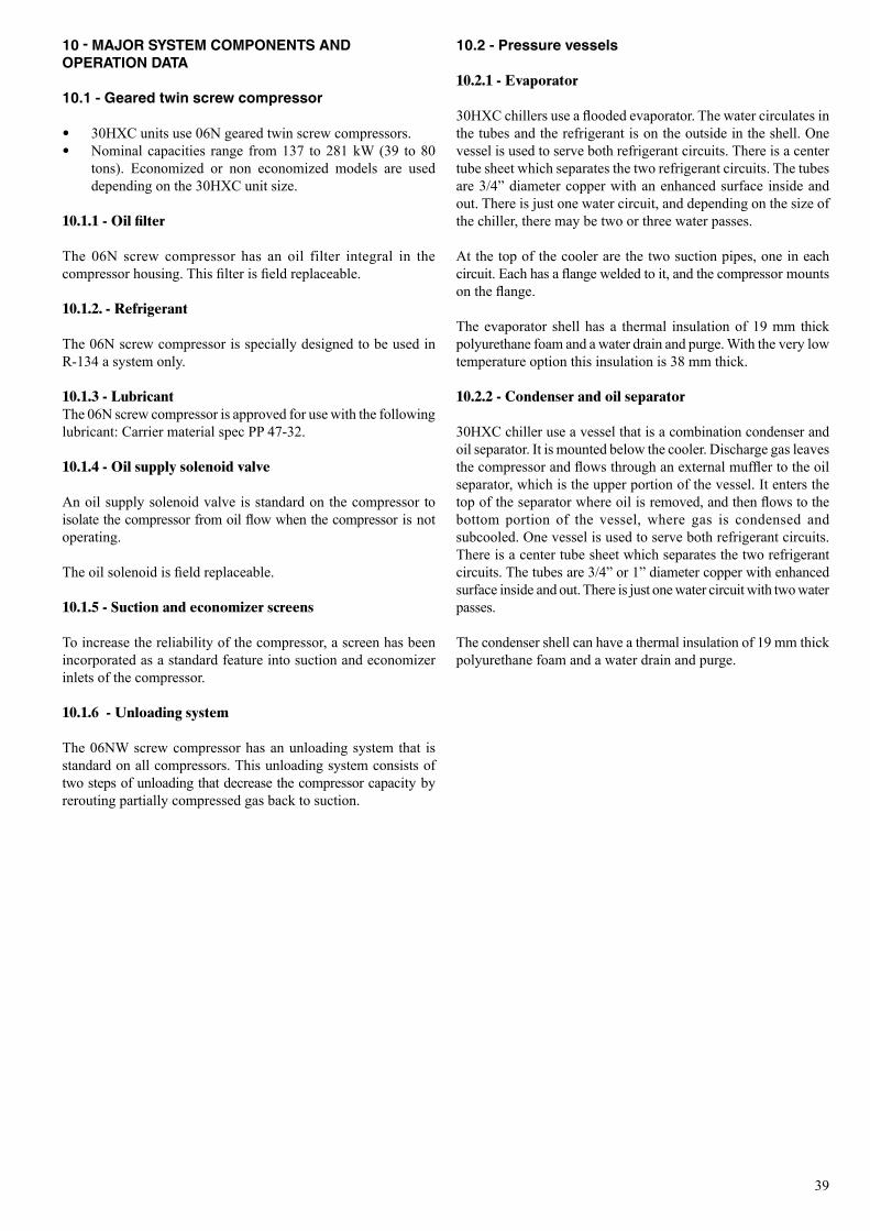
39
10 - MAJOR SYSTEM COMPONENTS AND OPERATION DATA
10.1 - Geared twin screw compressor
• 30HXC units use 06N geared twin screw compressors. • Nominal capacities range from 137 to 281 kW (39 to 80
tons). Economized or non economized models are used depending on the 30HXC unit size.
10.1.1 - Oil filter
The 06N screw compressor has an oil filter integral in the compressor housing. This filter is field replaceable.
10.1.2. - Refrigerant
The 06N screw compressor is specially designed to be used in R-134 a system only.
10.1.3 - LubricantThe 06N screw compressor is approved for use with the following lubricant: Carrier material spec PP 47-32.
10.1.4 - Oil supply solenoid valve
An oil supply solenoid valve is standard on the compressor to isolate the compressor from oil flow when the compressor is not operating. The oil solenoid is field replaceable.
10.1.5 - Suction and economizer screens
To increase the reliability of the compressor, a screen has been incorporated as a standard feature into suction and economizer inlets of the compressor.
10.1.6 - Unloading system
The 06NW screw compressor has an unloading system that is standard on all compressors. This unloading system consists of two steps of unloading that decrease the compressor capacity by rerouting partially compressed gas back to suction.
10.2 - Pressure vessels
10.2.1 - Evaporator
30HXC chillers use a flooded evaporator. The water circulates in the tubes and the refrigerant is on the outside in the shell. One vessel is used to serve both refrigerant circuits. There is a center tube sheet which separates the two refrigerant circuits. The tubes are 3/4” diameter copper with an enhanced surface inside and out. There is just one water circuit, and depending on the size of the chiller, there may be two or three water passes. At the top of the cooler are the two suction pipes, one in each circuit. Each has a flange welded to it, and the compressor mounts on the flange.
The evaporator shell has a thermal insulation of 19 mm thick polyurethane foam and a water drain and purge. With the very low temperature option this insulation is 38 mm thick.
10.2.2 - Condenser and oil separator
30HXC chiller use a vessel that is a combination condenser and oil separator. It is mounted below the cooler. Discharge gas leaves the compressor and flows through an external muffler to the oil separator, which is the upper portion of the vessel. It enters the top of the separator where oil is removed, and then flows to the bottom portion of the vessel, where gas is condensed and subcooled. One vessel is used to serve both refrigerant circuits. There is a center tube sheet which separates the two refrigerant circuits. The tubes are 3/4” or 1” diameter copper with enhanced surface inside and out. There is just one water circuit with two water passes.
The condenser shell can have a thermal insulation of 19 mm thick polyurethane foam and a water drain and purge.
40
10.3 - Electronic expansion device (EXV)
The microprocessor controls the EXV through the EXV control module. Inside this EXV is a linear actuator stepper motor. High-pressure liquid refrigerant enters the valve through the bottom. A series of calibrated slots are located inside the orifice assembly. As refrigerant passes through the orifice, the pressure drops and the refrigerant changes to a 2-phase condition (liquid and vapour). To control refrigerant flow for different operating conditions, the sleeve moves up and down over the orifice, thereby changing effective flow area of expansion device. The sleeve is moved by a linear stepper motor. The stepper motor moves in increments and is controlled directly by the processor module. As the stepper motor rotates, motion is transferred into linear movement by the lead screw. Through the stepper motor and lead screws, 1500 discrete steps of motion are obtained. The large number of steps and long stroke result in very accurate control of refrigerant flow.
At initial start-up, the EXV position is at zero. After that, the microprocessor keeps accurate track of the valve position in order to use this information as input for the other control functions. It does this by initializing the EXV’s at startup. The processor sends out enough closing pulses to the valve to move it from fully open to fully closed, then resets the position counter to zero. From this point on, until the initialization, the processor counts the total number of open and closed steps it has sent to each valve.
10.4 - Economizer
Economizers are installed on 30HXC 190, 285 and 375. The economizer improves both the chiller capacity and efficiency as well as providing motor cooling. The economizers used are direct-expansion plate heat exchangers.
The flow of the direct-expansion plate heat exchanger circuit is adjusted by the thermostatic cooling valves.
10.5 - Oil pumps
The 30HXC screw chillers use one externally mounted pre-lubricating oil pump per circuit. This pump is operated as part ot the start-up sequence.
ATTENTION: The operating temperature of the coil may reach 80°C. In certain temporary conditions (especially during start-up at low outside temperature or low condenser loop temperature) the oil pump can be reactivated.
10.6 - Motor cooling valves
Compressor motor winding temperatures are controlled to the optimum setpoint. The control accomplishes this by cycling the motor cooling solenoid valve to allow liquid refrigerant to flow across the motor windings as needed.
On units equipped with economizers with plate heat exchangers, a thermostatic valve controls the necessary refrigerant flow entering this heat exchanger and continuously flowing over the motor windings. All refrigerant used for motor cooling returns to the rotors and is compressed to the discharge pressure.
10.7 - Sensors
The units use thermistors to measure the temperature, and pressure transducers to control and regulate system operation (see 30GX/HXC - Pro-Dialog Plus Control IOM for a more detailed explanation).
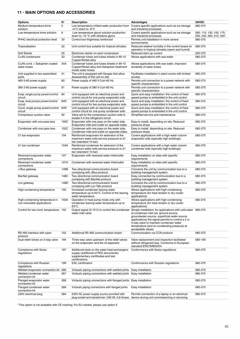
41
11 - MAIN OPTIONS AND ACCESSORIES
Options N° Description Advantages 30HXCMedium-temperaturebrinesolution
5 Lowtemperaturechilledwaterproductionfrom+5°C down to -6°C
Coversspecificapplicationssuchasicestorageand industrial processes
080-375
Low-temperaturebrinesolution 6 Lowtemperatureglycolsolutionproductiondown to -10 °C with ethylene glycol
Coversspecificapplicationssuchasicestorageand industrial processes
090,110,130,155,175,200, 230, 260, 310, 345*
IP44Celectricalprotectionlevel 20 Controlboxthightnessreinforced Permits unit installation in more severe envrionments
080-375
Tropicalisation 22 Unitcontrolboxsuitablefortropicalclimates Reducedrelativehumidityinthecontrolboxesforoperation in tropical climates (warm and humid)
080-375
Soft Starter 25 Electronic starter on each compressor Reduced start-up current 200-375Cu/Ni condensers 33 Condensertubesandtubessheetsin90-10
Copper/Nickel alloyAllows applications with sea water 080-375
Cu/Nicond.+Sakaphencoatedwaterboxes
34A Condensertubesandtubessheetsin90-10Copper/Nickel alloy and Sakaphen treatment insidewaterboxes
Allows applications with sea water, improved durabilityofwaterboxes
080-375
Unitsuppliedintwoassembledparts
51 Theunitisequippedwithflangesthatallowdisassemblyoftheunitonsite
Facilitates installation in plant rooms with limited access
080-375
460-3-60 power supply 60 Power supply of 460 V-3 ph-60 Hz Permits unit connection to a power network with specificcharacteristics
080-375
380-3-60 power supply 61 Power supply of 380 V-3 ph-60 Hz Permits unit connection to a power network with specificcharacteristics
080-375
Evap.singlepumppower/controlcircuit
84 Unitequippedwithanelectricalpowerandcontrol circuit for one pump evaporator side
Quickandeasyinstallation:thecontroloffixedspeedpumpsisembeddedintheunitcontrol
080-375
Evap.dualpumpspower/controlcircuit
84D Unitequippedwithanelectricalpowerandcontrol circuit for two pumps evaporator side
Quickandeasyinstallation:thecontroloffixedspeedpumpsisembeddedintheunitcontrol
080-375
Cond.singlepumppower/controlcircuit
84R Unitequippedwithanelectricalpowerandcontrol circuit for one pump condenser side
Quickandeasyinstallation:thecontroloffixedspeedpumpsisembeddedintheunitcontrol
080-375
Compressor suction valve 92 Valve set for the compressor suction side to isolate it in the refrigerant circuit
Simplifiedserviceandmaintenance 080-375
Evaporator with one pass less 100C Evaporatorwithonepassonthewaterside.Evaporatorinletandoutletonoppositesides.
Easytoinstall,dependingonsite.Reducedpressure drops
080-375
Condenser with one pass less 102C Condenserwithonepassonthewaterside.Condenserinletandoutletonoppositesides.
Easytoinstall,dependingonsite.Reducedpressure drops
080-375
21barevaporator 104 Reinforced evaporator for extension of the maximum water-side service pressure to 21 bar(standard10bar)
Covers applications with a high water column evaporatorside(typicallyhighbuildings)
080-375
21barcondenser 104A Reinforced condenser for extension of the maximum water-side service pressure to 21 bar(standard10bar)
Covers applications with a high water column condenserside(typicallyhighbuildings)
080-375
Reversed evaporator water connections
107 Evaporator with reversed water inlet/outlet Easyinstallationonsiteswithspecificrequirements
080-375
Reversed condenser water connections
107A Condenser with reversed water inlet/outlet Easyinstallationonsiteswithspecificrequirements
080-375
J-Bus gateway 148B Two-directionalcommunicationboardcomplying with JBus protocol
Connectstheunitbycommunicationbustoabuildingmanagementsystem
080-375
BacNet gateway 148C Two-directionalcommunicationboardcomplying with BacNet protocol
Easyconnectionbycommunicationbustoabuildingmanagementsystem
080-375
Longateway 148D Two-directionalcommunicationboardcomplyingwithLonTalkprotocol
Connectstheunitbycommunicationbustoabuildingmanagementsystem
080-375
High condensing temperature 150 Increasedcondenserleavingwatertemperatureupto63°C.Controloftheleavingwatertemperature.
Allows applications with high condensing temperature (for heat reclaim or dry cooler applications)
080-375
High condensing temperature in non-reversibleapplications
150A Operation in heat pump mode only with condenser leaving water temperature up to 63°C.
Allows applications with high condensing temperature (for heat reclaim or dry cooler applications)
080-375
Controlforlowcond.temperature 152 Output signal (0-10 V) to control the condenser water inlet valve
Simple installation: for applications with cold water atcondenserinlet(ex.ground-source,groundwater-source,superficialwater-sourceapplications) the signal permits to control a 2 or 3-way valve to maintain condenser water temperature (and so condensing pressure) at acceptablevalues
080-375
RS 485 interface with open protocol
155 AdditionalRS485communicationboard Communication via CCN protocol 080-375
Dualreliefvalveson3-wayvalve 194 Three-way valve upstream of the relief valves on the evaporator and the oil separator
Valve replacement and inspection facilitated withoutrefrigerantloss.ComformstoEuropeanstandardEN378/BGVD4
080-190
Compliance with Swiss regulations
197 Additional tests on the water heat exchangers: supply(additionalofPEDdocuments)supplementarycertificatesandtestcertifications
Conformance with Swiss regulations 080-375
Compliance with Russian regulations
199 EACcertification Conformance with Russian regulations 080-375
Welded evaporator connection kit 266 Victaulicpipingconnectionswithweldedjoints Easy installation 080-375Welded condenser water connection kit
267 Victaulicpipingconnectionswithweldedjoints Easy installation 080-375
Flanged evaporator water connection kit
268 Victaulicpipingconnectionswithflangedjoints Easy installation 080-375
Flanged condenser water connection kit
269 Victaulicpipingconnectionswithflangedjoints Easy installation 080-375
230V electrical plug 284 230V AC power supply source provided with plug socket and transformer (180 VA, 0,8 Amps)
Permits connection of a laptop or an electrical device during unit commissioning or servicing
080-375
*ThisoptionisnotavailablewithCEmarking.ForEUmarket,pleaseuseoption5
42
11.1 - Compressor suction valves (option 92)
These valves are designed to isolate the compressor from the rest of the circuit. Discharge valves, oil valves and cooling valves are installed in the standard unit. A label attached to the evaporator near each valve shows the open or closed position of the valve. It is important to remove the cap in order to manoeuvre the valve shaft and to replace it after this operation to ensure leak-tightness.
11.2 - Electric protection level of the 30HXC control boxes to IP44C (option 20)
The control boxes are leak-tight and equipped with a ventilation system to ensure cooling of the electrical components. The control box fan is controlled by a thermostat (setpoint 55°C, differential 20°C). A safety thermostat switches the unit off, if the control box temperature exceeds 60°C.
These elements can be shown on the unit and on the wiring diagram.
11.3 - Tropicalised control box for 30HXC units (option 22)
The control boxes are leak-tight and equipped with heaters. The standard components are already treated for “all-weather” operation. Heating the air will reduce the moisture level in the control box and prevent condensation.
11.4 - Disassembled 30HXC units (option 51)
These units are equipped with flange connections on the refrigerant piping to permit disassembly of the units without unwelding. The dimensional drawing for this option gives the weight of the different parts. The units are fully factory-assembled, charged with oil and refrigerant and run-tested at the end of the assembly line. The refrigerant charge is then removed and replaced by a nitrogen holding charge.
IMPORTANT: The oil charge remains in the unit and must not be exposed to moisture during disassembly and reassembly. The refrigerant charge is not supplied and must be provided on site. Please refer to the unit nameplate.
11.5 - Brine units for low-temperature evaporator leaving applications (option 5)
These units are verified for compatibility between unit and specific application down to -6°C water temperature. They have control configuration parameters that are matched to the application.
12 - MAINTENANCE
12.1 - Maintenance instructions
Air conditioning equipment must be maintained by professional technicians, whilst routine checks can be carried out locally by specialised technicians. See the standard EN 378-4.Simple preventive maintenance will allow you to get the best performance from your HVAC unit: • improved cooling performance • reduced power consumption • prevention of accidental component failure • prevention of major time-consuming and costly
interventions • protection of the environment
There are five maintenance levels for HVAC units, as defined by the AFNOR X60-010 standard.
External visual checks. These controls must be carried out: • After an intervention that is likely to affect the resistance or
a change in use or change of high-pressure refrigerant, or after a shut down of more than two years. Components that do not comply, must be changed. Test pressures above the respective component design pressure must not be applied.
• After repair or significant modifications or significant system or component extension.
• After re-installation at another site. • After repair following a refrigerant leak.
The frequency of refrigerant leak detection can vary from once per year for systems with less than 1% leak rate per year to once a day for systems with a leak rate of 35% per year or more. The frequency is in proportion with the leak rate.
NOTE: High leak rates are not acceptable. The necessary steps must be taken to eliminate any leak detected.
NOTE 2: Fixed refrigerant detectors are not leak detectors, as they cannot locate the leak.
12.2 - Soldering and welding
Component, piping and connection soldering and welding operations must be carried out using the correct procedures and by qualified operators. Pressurised containers must not be subjected to shocks, nor to large temperature variations during maintenance and repair operations.
12.3 - Refrigerant charging - adding charge
IMPORTANT: These units are designed for use with R-134a only. DO NOT USE ANY OTHER refrigerant in these units.
CAUTION: When adding or removing charge, circulate water through the condenser (HX) and cooler at all times to prevent freezing. Freezing damage is considered abuse and may void the Carrier warranty.
All refrigerant removal and draining operations must be carried out by a qualified technician and with the correct material for the unit. Any inappropriate handling can lead to uncontrolled fluid or pressure leaks.
CAUTION: DO NOT OVERCHARGE system. Over-charging results in higher discharge pressure with higher cooling fluid consumption, possible compressor damage and higher power consumption.

43
12.5 - Electrical maintenance
When working on the unit comply with all safety precautions decribed in section “Maintenance safety considerations”. • It is strongly recommended to change the fuses in the units
every 15000 operating hours or every 3 years. • It is recommended to verify that all electrical connections
are tight: - after the unit has been received at the moment of
installation and before the first start-up, - one month after the first start-up,when the electrical
components have reached their nominal operating temperatures,
- then regularly once a year.
12.6 - Pressure transducers
12.6.1 - Discharge pressure (circuits A and B)
This input is used to measure the high side pressure of each circuit of the unit. It is used to provide the pressure to replace the discharge pressure gauge and to control the head pressure.
12.6.2 - Suction pressure (circuits A and B)
This input is used to measure the pressure of the low side of the unit. It is used to provide the pressure to replace the suction pressure gauge.
12.6.3 - Oil pressure (each compressor)
This input is used to measure the oil pressure of each unit compressor. It is located on the oil pressure port of each compressor.
12.6.4 - Economizer pressure (circuits A and B)
This input is used to monitor the oil pressure differential supplied to the compressor.
12.7 - Oil charging - low oil recharging
12.7.1 - Addition of oil charge to 30HXC systems 1. If the 30HXC unit shuts-off repeatedly on Low oil Level, this
may be an indication of inadequate oil charge. It could also mean simply that oil is in the process of being reclaimed from the low-side of the system.
2. Begin by running the unit at full-load for an hour and a half. 3. After running for 1-1/2 hours allow the unit to re-start and run
normally. If the Low Oil Level alarms persist, the unit has a low oil charge. Add oil to the oil separator, using the oil charging valve at the bottom of the condenser.
CAUTION: Do NOT add oil at any other location as improper unit operation may result.
4. Make sure that the unit is not running when adding oil, as this will make the oil charging process easier. Because the system is under pressure even when the unit is not running, it will be necessary to use a suitable pump (hand or electric pump) to add oil to the system.
12.4 - Indication of low charge on a 30HXC system
NOTE : To check for low refrigerant charge on a 30HXC, several factors must be considered. A flashing liquid-line sightglass is not necessarily an indication of inadequate charge. There are many system conditions where a flashing sightglass occurs under normal operation. The 30HXC metering device is designed to work properly under these conditions.
1. Make sure that the circuit is running at a full-load condition. To check whether circuit A is fully loaded, follow the procedure described in the Controls manual.
2. It may be necessary to use the Manual Control feature to force the circuit into a full-load condition. If this is the case, see the instructions for using the Manual Control feature in the Controls manual.
3. With the circuit running at full-load, verify that the cooler leaving fluid temperature is in the range of 6°C ± 1.5 K.
4. At this condition, observe the refrigerant in the liquid line sightglass. If there is a clear sightglass, and no signs of flashing, then the circuit is adequately charged. Skip the remaining steps.
5. If the refrigerant appears to be flashing, the circuit is probably low on charge. Verify this by checking the EXV position (see 30GX/HXC Pro-Dialog Plus Controls IOM).
6. If the opening position of the EXV is greater than 60%, and if the liquid-line sightglass is flashing, then the circuit is low on charge. Follow the procedure for adding charge.
12.4.1 - To add charge to the 30HXC systems
1. Make sure that the unit is running at full-load, and that the cooler leaving fluid temperature is in the range of 5.6 to 7.8°C.
2. At these operating conditions, check the liquid-line sightglass. If there is a clear sightglass, then the unit has sufficient charge. If the sightglass is flashing, then check the EXV Percent Open. If this is greater than 60%, then begin adding charge.
NOTE: A flashing liquid-line sightglass at operating conditions other than those mentioned above is not necessarily an indication of low refrigerant charge.
3. Add 2.5 kg of liquid charge into the evaporator using the charging valve located on the top of the evaporator.
4. Observe the EXV Percent Open value. The EXV should begin closing as charge is being added. Allow the unit to stabilize. If the EXV Percent Open remains above 60%, and there are still bubbles in the sightglass, add an additional 2.5 kg of liquid charge.
5. Allow the unit to stabilize, and again check the EXV Percent Open. Continue adding 2.5 kg of liquid refrigerant charge at a time, and allow the unit to stabilize before checking the EXV position.
6. When the EXV Percent Open is in the range of 40-60%, check the liquid line sightglass. Slowly add enough additional liquid charge to ensure a clear sightglass. This should be done slowly to avoid overcharging the unit.
7. Verify adequate charge by continuing to run at full-load with 6°C ± 1.5 K evaporator leaving fluid temperature. Check that the refrigerant is not flashing in the liquid-line sightglass. The EXV Percent Open should be between 40 and 60%. The cooler level indicator should be in the range of 1.5 - 2.5.
44
5. Using a suitable pump, add 2 litres of Polyolester oil to the system (CARRIER SPEC: PP47-32). Make sure that the oil level safety switch is NOT jumpered, and allow the unit to re-start and run normally.
6. If low oil level problems persist, add another 1 or 2 litres of oil. If it is necessary to add more than 4 litres of oil to the system, then contact your Carrier distributor service department.
CAUTION: When transferring the refrigerant charge to a storage unit, oil may be carried along when the unit is not operating. Reuse first of all the amount of refrigerant transferred. After draining the oil, only recharge the amount drained (an excess oil charge may impair correct unit operation).
If an oil draining or recovery operation becomes necessary, the fluid transfer must be made using mobile containers.
12.8 - Integral oil filter change
An integral oil filter in the 06N screw compressor is specified to provide a high level of filtration (3 µ) required for long bearing life. As system cleanliness is critical to reliable system operation, there is also a prefilter (7 µ) in the oil line at the oil separator outlet.
The replacement integral oil filter element part number is:
Carrier part number (including filter and O-ring): 06NA 660016S.
12.9 - Filter change-out schedule
The filter should be checked after the first 1000 hours of operation, and every subsequent 4000 hours. The filter should be replaced at any time when the pressure differential across the filter exceeds 2.1 bar.
The pressure drop across the filter can be determined by measuring the pressure at the filter service port and the oil pressure port. The difference in these two pressures will be the pressure drop across the filter, check valve, and solenoid valve. The pressure drop across the check valve and solenoid valve is approximately 0.4 bar, which should be subtracted from the two oil pressure measurements to give the oil filter pressure drop. The oil filter pressure drop should be checked after any occasion that the compressor is shut down on a low oil pressure safety.
12.10 - Filter change-out procedure
The following steps outline the proper method of changing the integral oil filter.1. Shutdown and lockout the compressor.2. Manually force the operation of the oil solenoid valve, in order
to press the internal valve shutter onto its seat.3. Close the oil filter service valve. Bleed pressure from the
filter cavity through the filter service port.4. Remove the oil filter plug. Remove the old oil filter.5. Prior to installing the new oil filter, “grease” the o-ring with
oil. Install the filter and replace the plug. Before closing up the lube oil system, take the opportunity
to replace the prefilter, as well.6. When complete, evacuate the filter cavity through the filter
service port. Open the filter service valve. Remove any compressor lockout devices, the compressor is ready to return to operation.
12.11 - Compressor replacement
12.11.1 - Compressor rotation control
Correct compressor rotation is one of the most critical application considerations. Reverse rotation, even for a very short duration, damages the compressor.
The reverse rotation protection scheme must be capable of determining the direction of rotation and stopping the compressor within 300 milliseconds. Reverse rotation is most likely to occur whenever the wiring to the compressor terminals is disturbed.
To minimize the opportunity for reverse rotation, the following procedure must be applied. Rewire the power cables to the compressor terminal pin as originally wired.
For replacement of the compressor, a low pressure switch is included with the compressor. This low pressure switch should be temporarily installed as a hard safety on the high pressure part of the compressor. The purpose of this switch is to protect the compressor against any wiring errors at the compressor terminal pin. The electrical contact of the switch would be wired in series with the high pressure switch. The switch will remain in place until the compressor has been started and direction of rotation has been verified; at this point, the switch will be removed.
The switch that has been selected for detecting reverse rotation is Carrier part number HK01CB001. It is available as part of the “Compressor installation package” (part No. 06NA 660 013). This switch opens the contacts when the pressure falls below 6.8 kPa absolute. The switch is a manual reset type that can be reset after the pressure has once again risen above 69 kPa relative. It is critical that the switch be a manual reset type to preclude the compressor from short cycling in the reverse direction.

45
12.11.2 - EXV troubleshooting procedure
Follow steps below to diagnose and correct EXV problems.
Check EXV motor operation first (see procedure in the 30GX/HXC Pro-Dialog Plus Controls IOM). You should be able to feel the actuator moving by placing your hand on the EXV. You should feel a hard knocking come from the actuator when it reaches the top of its stroke (can be heard if surroundings are relatively quiet). The actuator should knock when it reaches the bottom of its stroke. If it is believed that the valve is not working properly, contact your Carrier service department for further checks on: • output signals on EXV module • wire connections (continuity and tight connection at all pin
terminals) • resistance of the EXV motor windings.
12.12 - Corrosion control
All metallic parts of the unit (chassis, casing panels, control boxes, heat exchangers etc.) are protected against corrosion by a coating of powder or liquid paint. To prevent the risk of blistering corrosion that can appear when moisture penetrates under the protective coatings, it is necessary to carry out periodic checks of the coating (paint) condition.
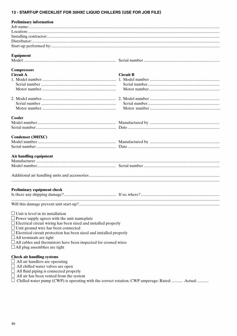
46
13 - START-UP CHECKLIST FOR 30HXC LIQUID CHILLERS (USE FOR JOB FILE)
Preliminary informationJob name: ...............................................................................................................................................................................................Location: ................................................................................................................................................................................................Installing contractor: .............................................................................................................................................................................Distributor: ............................................................................................................................................................................................Start-up performed by: .........................................................................................................................................................................
EquipmentModel: ............................................................................................ Serial number ............................................................................
CompressorsCircuit A Circuit B1. Model number .......................................................................... 1. Model number ...................................................................... Serial number ........................................................................... Serial number ........................................................................ Motor number .......................................................................... Motor number ....................................................................... 2. Model number .......................................................................... 2. Model number ...................................................................... Serial number ........................................................................... Serial number ........................................................................ Motor number .......................................................................... Motor number ....................................................................... CoolerModel number ............................................................................... Manufactured by ......................................................................Serial number ................................................................................ Date ............................................................................................
Condenser (30HXC)Model number ............................................................................... Manufactured by ......................................................................Serial number ................................................................................ Date ............................................................................................ Air handling equipmentManufacturer ........................................................................................................................................................................................Model number ............................................................................... Serial number ............................................................................
Additional air handling units and accessories ....................................................................................................................................................................................................................................................................................................................................................
Preliminary equipment checkIs there any shipping damage? .................................................... If so, where? ................................................................................................................................................................................................................................................................................................Will this damage prevent unit start-up? .............................................................................................................................................
Unit is level in its installation Power supply agrees with the unit nameplate Electrical circuit wiring has been sized and installed properly Unit ground wire has been connected Electrical circuit protection has been sized and installed properly All terminals are tight All cables and thermistors have been inspected for crossed wires All plug assemblies are tight
Check air handling systems All air handlers are operating All chilled water valves are open All fluid piping is connected properly All air has been vented from the system Chilled water pump (CWP) is operating with the correct rotation. CWP amperage: Rated: ........... Actual: ...........
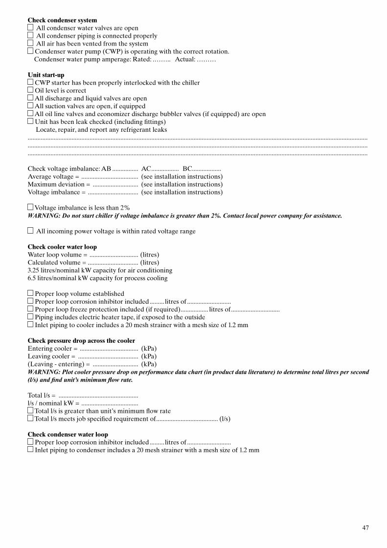
47
Check condenser system All condenser water valves are open All condenser piping is connected properly All air has been vented from the system Condenser water pump (CWP) is operating with the correct rotation.
Condenser water pump amperage: Rated: .…….. Actual: ………
Unit start-up CWP starter has been properly interlocked with the chiller Oil level is correct All discharge and liquid valves are open All suction valves are open, if equipped All oil line valves and economizer discharge bubbler valves (if equipped) are open Unit has been leak checked (including fittings)
Locate, repair, and report any refrigerant leaks...................................................................................................................................................................................................................................................................................................................................................................................................................................................................................................................................................................................................................................................
Check voltage imbalance: AB ................ AC ................. BC..................Average voltage = ................................... (see installation instructions)Maximum deviation = ............................ (see installation instructions)Voltage imbalance = ............................... (see installation instructions)
Voltage imbalance is less than 2%WARNING: Do not start chiller if voltage imbalance is greater than 2%. Contact local power company for assistance.
All incoming power voltage is within rated voltage range
Check cooler water loopWater loop volume = .............................. (litres)Calculated volume = ............................... (litres)3.25 litres/nominal kW capacity for air conditioning6.5 litres/nominal kW capacity for process cooling
Proper loop volume established Proper loop corrosion inhibitor included ......... litres of ........................... Proper loop freeze protection included (if required) ................. litres of .............................. Piping includes electric heater tape, if exposed to the outside Inlet piping to cooler includes a 20 mesh strainer with a mesh size of 1.2 mm
Check pressure drop across the coolerEntering cooler = .................................... (kPa)Leaving cooler = ..................................... (kPa)(Leaving - entering) = ............................ (kPa)WARNING: Plot cooler pressure drop on performance data chart (in product data literature) to determine total litres per second (l/s) and find unit’s minimum flow rate.
Total l/s = ................................................. l/s / nominal kW = ...................................
Total l/s is greater than unit’s minimum flow rate Total l/s meets job specified requirement of ...................................... (l/s)
Check condenser water loop Proper loop corrosion inhibitor included ......... litres of ........................... Inlet piping to condenser includes a 20 mesh strainer with a mesh size of 1.2 mm
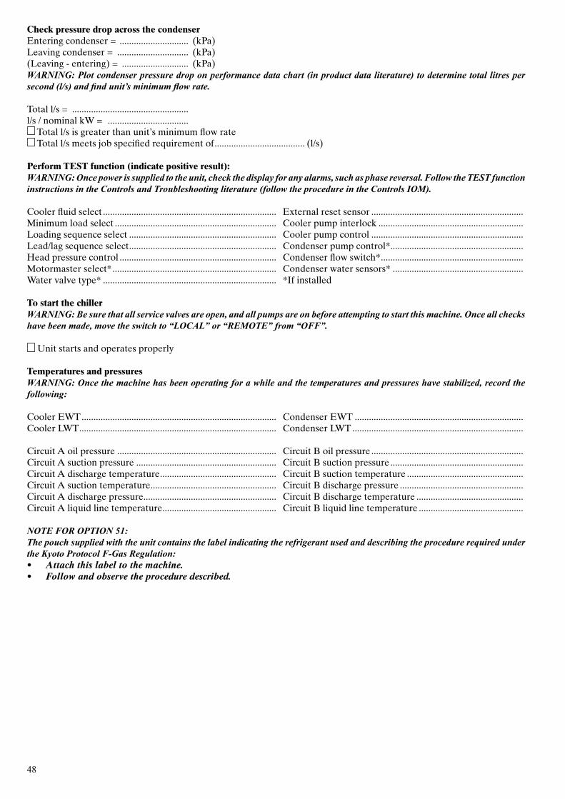
48
Check pressure drop across the condenserEntering condenser = ............................. (kPa)Leaving condenser = .............................. (kPa)(Leaving - entering) = ............................ (kPa)WARNING: Plot condenser pressure drop on performance data chart (in product data literature) to determine total litres per second (l/s) and find unit’s minimum flow rate.
Total l/s = ................................................. l/s / nominal kW = ..................................
Total l/s is greater than unit’s minimum flow rate Total l/s meets job specified requirement of ...................................... (l/s)
Perform TEST function (indicate positive result):WARNING: Once power is supplied to the unit, check the display for any alarms, such as phase reversal. Follow the TEST function instructions in the Controls and Troubleshooting literature (follow the procedure in the Controls IOM).
Cooler fluid select ......................................................................... External reset sensor ................................................................Minimum load select .................................................................... Cooler pump interlock .............................................................Loading sequence select .............................................................. Cooler pump control ................................................................Lead/lag sequence select .............................................................. Condenser pump control*........................................................Head pressure control .................................................................. Condenser flow switch* ............................................................Motormaster select* ..................................................................... Condenser water sensors* .......................................................Water valve type* ......................................................................... *If installed
To start the chillerWARNING: Be sure that all service valves are open, and all pumps are on before attempting to start this machine. Once all checks have been made, move the switch to “LOCAL” or “REMOTE” from “OFF”.
Unit starts and operates properly
Temperatures and pressuresWARNING: Once the machine has been operating for a while and the temperatures and pressures have stabilized, record the following:
Cooler EWT .................................................................................. Condenser EWT .......................................................................Cooler LWT ................................................................................... Condenser LWT ........................................................................
Circuit A oil pressure ................................................................... Circuit B oil pressure ................................................................Circuit A suction pressure ........................................................... Circuit B suction pressure ........................................................Circuit A discharge temperature ................................................. Circuit B suction temperature .................................................Circuit A suction temperature ..................................................... Circuit B discharge pressure ....................................................Circuit A discharge pressure........................................................ Circuit B discharge temperature .............................................Circuit A liquid line temperature ................................................ Circuit B liquid line temperature ............................................
NOTE FOR OPTION 51:The pouch supplied with the unit contains the label indicating the refrigerant used and describing the procedure required under the Kyoto Protocol F-Gas Regulation:• Attach this label to the machine.• Follow and observe the procedure described.


OrderNo:13050,01.2017-SupersedesorderNo:13050,05.2016. Manufacturer:CarrierSCS,Montluel,France.Manufacturerreservestherighttochangeanyproductspecificationswithoutnotice. PrintedintheEuropeanUnion.