installation, operation, and maintenance guide · 7. when a furnace is installed so that supply...
TRANSCRIPT
INSTALLATION, OPERATION,AND MAINTENANCE GUIDE
ALL phases of this installation must comply with NATIONAL, STATE AND LOCAL CODES
Model:CUX1B040A9241ACUX1B060A9361ACUX1B080A9421ACUX1C100A9481ACUX1D100A9601ACUX1D120A9601A
CDX1B040A9241ACDX1B060A9361ACDX1B080A9421ACDX1C100A9481ACDX1D120A9601A
IMPORTANT — This Document is customer property and is to remain with this unit.Please return to service information pack upon completion of work.
© 2008 American Standard Heating & Air Conditioning All Rights Reserved
Upflow / Horizontal* andDownflow / Horizontal*,Single Stage Direct Vent Gas-Fired Condensing Furnaces
* Models can ONLY be rotatedto LEFT Side for horizontal installation
Upflow / Horizontal* Downflow / Horizontal*
Since the manufacturer has a policy of continuous product and product dataimprovement, it reserves the right to change design and specifications without notice.
41- 5016- 07
A341624P07
Installation Instructions
Pub. No. 41-5016-07Page 2
SAFETY SECTION
The following safety practices and precautions must be followedduring the installation, servicing, and operation of this furnace.
1. Use only with the type of gas approved for this furnace. Referto the furnace rating plate.
2. Install this furnace only in a location and position as speci-fied in “Location and Clearances” (page 3), of these instruc-tions.
3. Provide adequate combustion and ventilation air to the fur-nace space as specified in “Air for Combustion and Ventila-tion” (pages 7-8), of these instructions.
4. Combustion products must be discharged outdoors. Connectthis furnace to an approved vent system only, as specified inthe “Venting” section (pages 11-21), of these instructions.
5. Never test for gas leaks with an open flame. Use a commer-cially available soap solution made specifically for the detec-tion of leaks to check all connections, as specified in “GasPiping” (page 27), of these instructions.
6. Always install the furnace to operate within the furnace’sintended temperature-rise range with a duct system whichhas an external static pressure within the allowable range, asspecified on the unit rating plate. Airflow with temperaturerise for cfm versus static is shown in the Service Factsaccompanying this furnace.
7. When a furnace is installed so that supply ducts carry aircirculated by the furnace to areas outside the space contain-ing the furnace, the return air shall also be handled by aduct(s) sealed to the furnace casing and terminating outsidethe space containing the furnace.
8. A gas-fired furnace for installation in a residential garagemust be installed as specified in “Location and Clearances”section (page 3), of these instructions.
9. The furnace may be used for temporary heating of buildingsor structures under construction only when the followingconditions have been met:
a. The furnace venting system must be complete and in-stalled per manufacturer’s instructions.
b. The furnace is controlled only by a room thermostat (nofield jumpers).
c. The furnace return air duct must be complete and sealedto the furnace and clean air filters are in place.
d. The furnace input rate and temperature rise must beverified to be within nameplate marking.
e. 100% of the furnace combustion air requirement mustcome from outside the structure.
f. The furnace return air temperature range is between55 and 80 degrees Fahrenheit.
g. Clean the furnace, duct work, and components uponsubstantial completion of the construction process, andverify furnace operating conditions including ignition,input rate, temperature rise and venting, according to themanufacturer’s instructions.
10.This product must be gas piped by a Licensed Plumber or GasFitter in the Commonwealth of Massachusetts. ▲ WARNING!
FIRE OR EXPLOSION HAZARD
Failure to follow the safety warnings exactly could result inserious injury, death or property damage.
Improper servicing could result in dangerous operation,serious injury, death, or property damage.
CARBON MONOXIDE POISONING HAZARD
Failure to follow the steps outlined below for each appliance connected to the venting system being placed into operation could result in carbon monoxide poisoning or death.
The following steps shall be followed for each appliance connected to the venting system being placed into operation, while all other appliances connected to the venting system are not in operation:
1. Seal any unused openings in the venting system.
2. Inspect the venting system for proper size and horizontal pitch, as required in the National Fuel Gas Code, ANSI Z223.1/NFPA 54 or the CAN/CGA B149 Installation Codes and these instructions. Determine that there is no blockage or restriction, leakage, corrosion and other deficiencies which could cause an unsafe condition.
3. As far as practical, close all building doors and windows and all doors between the space in which the appliance(s) connected to the venting system are located and other deficiencies which could cause an unsafe condition.
4. Close fireplace dampers.
5. Turn on clothes dryers and any appliance not connected to the venting system. Turn on any exhaust fans, such as range hoods and bathroom exhausts, so they are operating at maximum speed. Do not operate a summer exhaust fan.
6. Follow the lighting instructions. Place the appliance being inspected into operation. Adjust the thermostat so appliance is operating continuously.
7. If improper venting is observed during any of the above tests, the venting system must be corrected in accordance with the National Fuel Gas Code, ANSI Z221.1/NFPA 54 and/or CAN/CGA B149 Installation Codes.
8. After it has been determined that each appliance connected to the venting system properly vents where tested as outlined above, return doors, windows, exhaust fans, fireplace dampers and any other gas-fired burning appliance to their previous conditions of use.
▲ WARNING!
Safety signal words are used to designate a degree or level ofseriousness associated with a particular hazard. The signal wordsfor safety markings are WARNING and CAUTION.
a. WARNING indicates a potentially hazardous situation which,if not avoided, could result in death or serious injury.
b. CAUTION indicates a potentially hazardous situation which,if not avoided, may result in minor or moderate injury. It is alsoused to alert against unsafe practices and hazards involvingonly property damage.
Installation Instructions
Page 3Pub. No. 41-5016-07
CONTENTS
INSTALLATION INSTRUCTIONS .............. 1-31General Installation Instructions ................ 3Location and Clearances .............................. 3Outline Drawings ...................................... 4-5Horizontal Installation ................................. 6Air for Combustion and Ventilation ............ 7-8Duct Connections .......................................... 8Return Air Filters ......................................... 9General Venting Instructions ....................... 11-22Venting Materials ......................................... 11Condensate Piping ......................................... 22-24Field Wiring Diagrams ............................. 26Gas Piping ..................................................... 27-29Combustion and Input Check ....................... 27High Altitude Derate ..................................... 29
START-UP AND ADJUSTMENT .................. 29Preliminary Inspections ................................ 29Lighting Instructions .................................... 30Sequence of Operation .................................. 30Control and Safety Switch Adjustments ....... 30Airflow Adjustment ....................................... 30Abnormal Conditions ..................................... 31
OWNER’S INFORMATION ........................... 32-38Warranties ..................................................... 50-51
SERVICE INSTRUCTIONS .......................... 39-49Product Specifications ................................... 40-41Airflow ............................................................ 42-43Periodic Servicing Requirements ................. 44IFC Fault Codes ............................................ 45Unit Wiring Diagram .................................... 46-49
▲ CAUTION!To prevent shortening its service life, the furnace should notbe used as a “Construction Heater” during the finishingphases of construction until the requirements listed in item 9,a-g of the safety section of this publication have been met.Condensate in the presence of chlorides and fluorides frompaint, varnish, stains, adhesives, cleaning compounds, andcement create a corrosive condition which may cause rapiddeterioration of the heat exchanger.
▲ CAUTION!Do NOT install the furnace in a corrosive or contaminatedatmosphere.
GENERAL
The manufacturer assumes no responsibility for equipment in-stalled in violation of any code or regulation.
It is recommended that Manual J of the Air Conditioning Contrac-tors Association (ACCA) or A.R.I. 230 be followed in estimatingheating requirements. When estimating heating requirements forinstallation at altitudes above 2000 ft., remember the gas inputmay need to be reduced (See High Altitude Installation).
Material in this shipment has been inspected at the factoryand released to the transportation agency without knowndamage. Inspect exterior of carton for evidence of roughhandling in shipment. Unpack carefully after moving equip-ment to approximate location. If damage to contents isfound, report the damage immediately to the deliveringagency.
Codes and local utility requirements governing the installation ofgas fired equipment, wiring, plumbing, and flue connections mustbe adhered to. In the absence of local codes, the installation mustconform with latest edition of the National Fuel Gas Code ANSIZ223.1 • National Installation Code, CAN/CGA B149.1. Thelatest code may be obtained from the American Gas AssociationLaboratories, 400 N. Capitol St. NW, Washington D.C. 20001.1-800-699-9277 or www.aga.org
These furnaces have been classified as CATEGORY IV furnacesin accordance with latest edition of ANSI Z21.47 • CAN/CGA 2.3standards. Category IV furnaces operate with positive vent staticpressure and with a flue loss less than 17 percent. These conditionsrequire special venting systems, which must be gas tight and watertight.
LOCATION AND CLEARANCES
The location of the furnace is normally selected by the architect, thebuilder, or the installer. However, before the furnace is moved intoplace, be sure to consider the following requirements:
1. Is the location selected as near the chimney or vent and ascentralized for heat distribution as practical?
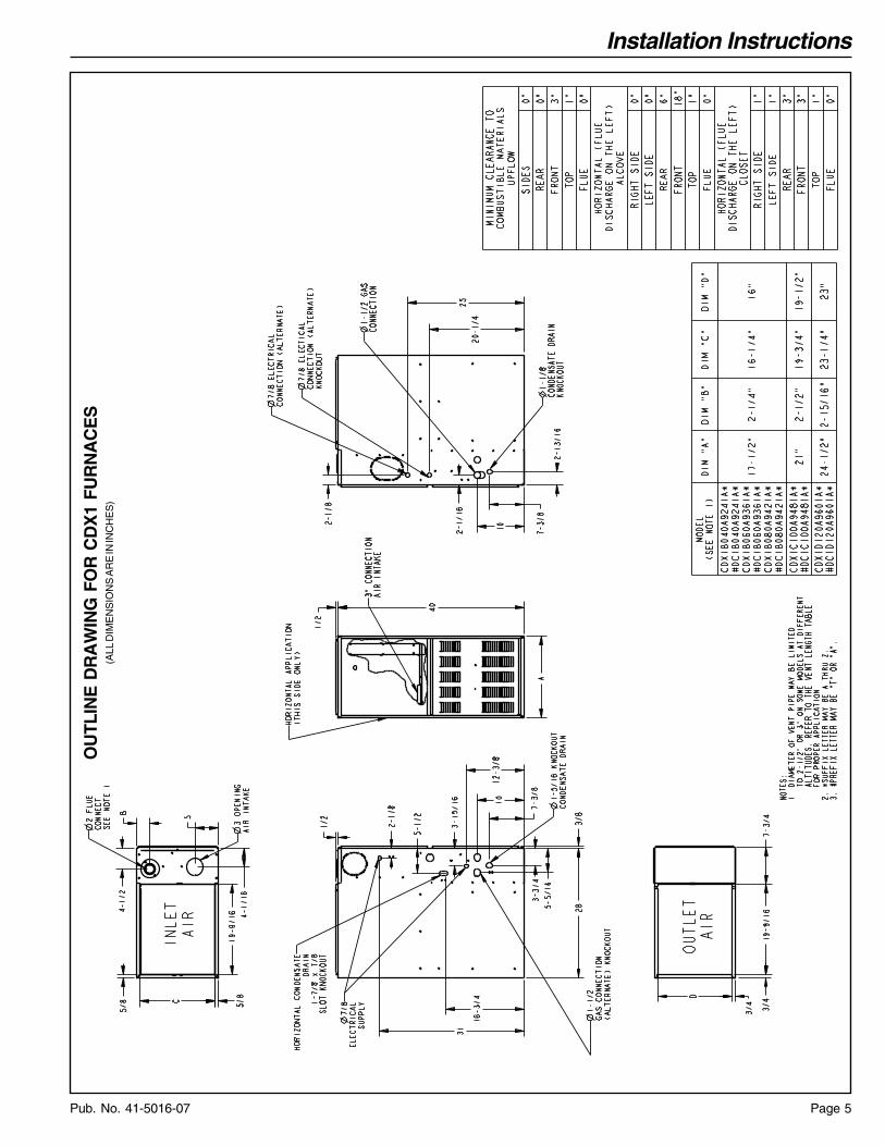
2. Do all clearances between the furnace and enclosure equal orexceed the minimums stated in Clearance Table on the OutlineDrawings?
3. Is there sufficient space for servicing the furnace and otherequipment? A minimum of 24 inches front accessibility to thefurnace must be provided. Any access door or panel must permitremoval of the largest component.
4. Are there at least 3 inches of clearance between the furnacecombustion air openings in the front panel and any closed panelor door provided?
5. Are the ventilation and combustion air openings large enoughand will they remain unobstructed? If outside air is used, are theopenings set above the highest snow accumulation level? (See theAir for Combustion and Ventilation section.)
6. Allow sufficient height in supply plenum above the furnace toprovide for cooling coil installation, if the cooling coil is notinstalled at the time of this furnace installation.
7. A furnace shall be installed so electrical components areprotected from water.
8. If the furnace is installed in a residential garage, it mustbe installed so that the burners, and the ignition source arelocated not less than 18 inches above the floor and the furnacemust be located or protected to avoid physical damage fromvehicles.
IMPORTANT:The furnace must be installed level. The only allowable variationwould be slightly to the left and/or forward in upflow installations orslightly toward the front in horizontal installations. This is necessaryfor proper condensate drainage.
INSTALLATION INSTRUCTIONS
▲ CAUTION!Disconnect all electric power including remote disconnectsbefore servicing, insure that all motor capacitors have dis-charged stored voltage.

Installation Instructions
Pub. No. 41-5016-07Page 4
OU
TLIN
E D
RA
WIN
G F
OR
CU
X1
FUR
NA
CE
S(A
LL D
IME
NS
ION
S A
RE
IN IN
CH
ES
)
Installation Instructions
Page 5Pub. No. 41-5016-07
OU
TLIN
E D
RA
WIN
G F
OR
CD
X1
FUR
NA
CE
S(A
LL D
IME
NS
ION
S A
RE
IN IN
CH
ES
)
Installation Instructions
Pub. No. 41-5016-07Page 6
The downflow furnace may be installed in an attic or crawl spacein the horizontal position by placing the furnace on the left side (asviewed from the front in the vertical position). The horizontalfurnace installation in an attic should be on a service platformlarge enough to allow for proper clearances on all sides and serviceaccess to the front of the furnace (See Outline Drawings). Linecontact is only permissible between lines formed by intersectionsof the top and two sides of the furnace casing and building joists,studs, or framing.
The furnace may be placed horizontally in a crawl space on a pador other noncombustible material which will raise the unit forsufficient protection from moisture. The furnace must be sup-ported at both ends and the middle when installed horizon-tally. The furnace must also be elevated approximately4-6 inches to allow clearance for the condensate drain toexit the cabinet in the horizontal position.
The horizontal furnace may also be suspended from the joistsusing 3/8" all-thread rods with pieces of angle iron underneath thefurnace to form a hanging rack at both ends and the midpoint. Therods need to be of sufficient length to allow for proper clearancesfrom combustible materials. The angle iron needs to be at least 32"in length to allow for access to service panels.
The upflow furnace, converted to horizontal, aligns and attachesthe TXC coil to the same flanges used in vertical. The coil needs tohave additional support.
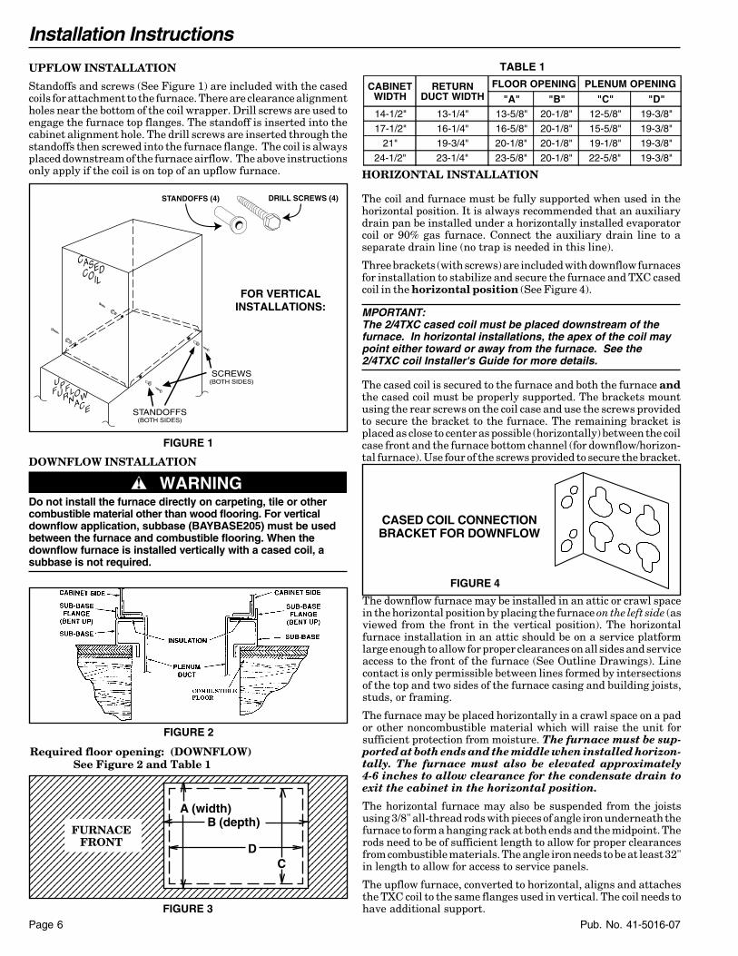
UPFLOW INSTALLATION
Standoffs and screws (See Figure 1) are included with the casedcoils for attachment to the furnace. There are clearance alignmentholes near the bottom of the coil wrapper. Drill screws are used toengage the furnace top flanges. The standoff is inserted into thecabinet alignment hole. The drill screws are inserted through thestandoffs then screwed into the furnace flange. The coil is alwaysplaced downstream of the furnace airflow. The above instructionsonly apply if the coil is on top of an upflow furnace. HORIZONTAL INSTALLATION
The coil and furnace must be fully supported when used in thehorizontal position. It is always recommended that an auxiliarydrain pan be installed under a horizontally installed evaporatorcoil or 90% gas furnace. Connect the auxiliary drain line to aseparate drain line (no trap is needed in this line).
Three brackets (with screws) are included with downflow furnacesfor installation to stabilize and secure the furnace and TXC casedcoil in the horizontal position (See Figure 4).
MPORTANT:The 2/4TXC cased coil must be placed downstream of thefurnace. In horizontal installations, the apex of the coil maypoint either toward or away from the furnace. See the2/4TXC coil Installer's Guide for more details.
The cased coil is secured to the furnace and both the furnace andthe cased coil must be properly supported. The brackets mountusing the rear screws on the coil case and use the screws providedto secure the bracket to the furnace. The remaining bracket isplaced as close to center as possible (horizontally) between the coilcase front and the furnace bottom channel (for downflow/horizon-tal furnace). Use four of the screws provided to secure the bracket.
CASED COIL CONNECTIONBRACKET FOR DOWNFLOW
FIGURE 4
DOWNFLOW INSTALLATION
▲ WARNING!Do not install the furnace directly on carpeting, tile or othercombustible material other than wood flooring. For verticaldownflow application, subbase (BAYBASE205) must be usedbetween the furnace and combustible flooring. When thedownflow furnace is installed vertically with a cased coil, asubbase is not required.
UPFLOWFURNACE
CASEDCOIL
SCREWS(BOTH SIDES)
STANDOFFS(BOTH SIDES)
FOR VERTICALINSTALLATIONS:
FIGURE 1
STANDOFFS (4) DRILL SCREWS (4)
FIGURE 2
Required floor opening: (DOWNFLOW)See Figure 2 and Table 1
FIGURE 3
123456789012345678901234567890121234567890123456789123456789012345678901234567890121234567890123456789123456789012345678901234567890121234567890123456789123456789012345678901234567890121234567890123456789123456789012345678901234567890121234567890123456789123456789012345678901234567890121234567890123456789123456789012345678901234567890121234567890123456789123456789012345678901234567890121234567890123456789123456789012345678901234567890121234567890123456789123456789012345678901234567890121234567890123456789123456789012345678901234567890121234567890123456789123456789012345678901234567890121234567890123456789123456789012345678901234567890121234567890123456789123456789012345678901234567890121234567890123456789123456789012345678901234567890121234567890123456789123456789012345678901234567890121234567890123456789123456789012345678901234567890121234567890123456789123456789012345678901234567890121234567890123456789123456789012345678901234567890121234567890123456789123456789012345678901234567890121234567890123456789
A (width)B (depth)
CD
FURNACEFRONT
TABLE 1
CABINETWIDTH
RETURNDUCT WIDTH
FLOOR OPENING PLENUM OPENING
"A" "B" "C" "D"14-1/2" 13-1/4" 13-5/8" 20-1/8" 12-5/8" 19-3/8"
17-1/2" 16-1/4" 16-5/8" 20-1/8" 15-5/8" 19-3/8"
21" 19-3/4" 20-1/8" 20-1/8" 19-1/8" 19-3/8"
24-1/2" 23-1/4" 23-5/8" 20-1/8" 22-5/8" 19-3/8"

Installation Instructions
Page 7Pub. No. 41-5016-07
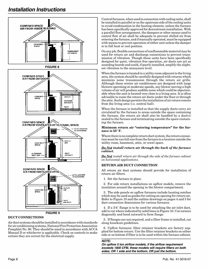
Confined spaces are installations with less than 50 cu. ft. of spaceper 1000 BTU/hr. input from all equipment installed. Air forcombustion and ventilation requirements can be supplied frominside the building as in Figure 8 or from the outdoors, as inFigure 9.
1. All air from inside the building as in Figure 8: The confinedspace shall be provided with two permanent openings communi-cating directly with an additional room(s) of sufficient volume sothat the combined volume of all spaces meets the criteria for anunconfined space. The total input of all gas utilization equipmentinstalled in the combined space shall be considered in makingthis determination. Refer to Table 3, for minimum open areasrequired.
2. All air from outdoors as in Figure 9: The confined space shallbe provided with two permanent openings, one commencingwithin 12 inches of the top and one commencing within 12 inchesof the bottom of the enclosure. The openings shall communicatedirectly, or by ducts, with the outdoors or spaces (crawl or attic)that freely communicate with the outdoors. Refer to Table 3, forminimum open areas required.
3. The following types of installations will require use ofOUTDOOR AIR for combustion, due to chemical exposures:
* Commercial buildings* Buildings with indoor pool* Furnaces installed in commercial laundry rooms* Furnaces installed in hobby or craft rooms* Furnaces installed near chemical storage areas.
Exposure to the following substances in the combustion airsupply will also require OUTDOOR AIR for combustion:
* Permanent wave solutions* Chlorinated waxes and cleaners* Chlorine based swimming pool chemicals* Water softening chemicals* Deicing salts or chemicals* Carbon Tetrachloride* Halogen type refrigerants* Cleaning solvents (such as perchloroethylene)* Printing inks, paint removers, varnish, etc.* Hydrochloric acid* Cements and glues* Antistatic fabric softeners for clothes dryers* Masonry acid washing materials
AIR FOR COMBUSTION AND VENTILATION
Adequate flow of combustion and ventilating air must not beobstructed from reaching the furnace. Air openings provided in thefurnace casing must be kept free of obstructions which restrict theflow of air. Airflow restrictions affect the efficiency and safeoperation of the furnace. Keep this in mind should you choose toremodel or change the area which contains your furnace. Furnacesmust have a free flow of air for proper performance.
Provisions for combustion and ventilation air shall be made inaccordance with “latest edition” of Section 5.3, Air for Combustionand Ventilation, of the National Fuel Gas Code, ANSI Z223.1, orSections 7.2, 7.3 or 7.4 of CAN/CGA B149 Installation Codes, andapplicable provisions of the local building codes. Special condi-tions created by mechanical exhausting of air and fireplaces mustbe considered to avoid unsatisfactory furnace operation.
Furnace locations may be in “confined space” or “unconfinedspace”. Unconfined space is defined in Table 2 and Figure 6. Thesespaces may have adequate air by infiltration to provide air forcombustion, ventilation, and dilution of flue gases. Buildings withtight construction (for example, weather stripping, heavily insu-lated, caulked, vapor barrier, etc.), may need additional air pro-vided as described for confined space.
TABLE 2
MINIMUM AREA IN SQUARE FEETFOR UNCONFINED SPACE INSTALLATIONSFURNACE
MAXIMUM BTUHINPUT RATING
WITH 8 FT. CEILINGMINIMUM AREA IN SQUARE
FEET OF UNCONFINED SPACE
40,00060,00080,000100,000120,000
250375500625875
MINIMUM FREE AREA IN SQUARE INCHESEACH OPENING (FURNACE ONLY)
FurnaceMaximum
BTUH/INPUTRating
AirFromInside
Air From Outside
Vertical Duct
Horizontal Duct
40,00060,00080,000100,000120,000
100100100100120
1015202530
2030405060
TABLE 3FIGURE 6
50 CU. FT. OR MOREPER 1000 BTU/HR. INPUTALL EQUIP. INSTALLED
UNCONFINED
CONFINED
FIGURE 7
LESS THAN 50 CU. FT.PER 1000 BTU/HR. INPUTALL EQUIP INSTALLED
FIGURE 5
UPFLOW/HORIZONTAL
Installation Instructions
Pub. No. 41-5016-07Page 8
DUCT CONNECTIONS
Air duct systems should be installed in accordance with standardsfor air conditioning systems, National Fire Protection AssociationPamphlet No. 90. They should be sized in accordance with ACCAManual D or whichever is applicable. Check on controls to makecertain they are correct for the electrical supply.
FIGURE 9
Central furnaces, when used in connection with cooling units, shallbe installed in parallel or on the upstream side of the cooling unitsto avoid condensation in the heating element, unless the furnacehas been specifically approved for downstream installation. Witha parallel flow arrangement, the dampers or other means used tocontrol flow of air shall be adequate to prevent chilled air fromentering the furnace, and if manually operated, must be equippedwith means to prevent operation of either unit unless the damperis in full heat or cool position.
On any job, flexible connections of nonflammable material may beused for return air and discharge connections to prevent trans-mission of vibration. Though these units have been specificallydesigned for quiet, vibration free operation, air ducts can act assounding boards and could, if poorly installed, amplify the slight-est vibration to the annoyance level.
When the furnace is located in a utility room adjacent to the livingarea, the system should be carefully designed with returns whichminimize noise transmission through the return air grille.Although these winter air conditioners are designed with largeblowers operating at moderate speeds, any blower moving a highvolume of air will produce audible noise which could be objection-able when the unit is located very close to a living area. It is oftenadvisable to route the return air ducts under the floor or throughthe attic. Such design permits the installation of air return remotefrom the living area (i.e. central hall).
When the furnace is installed so that the supply ducts carry aircirculated by the furnace to areas outside the space containingthe furnace, the return air shall also be handled by a duct(s)sealed to the furnace and terminating outside the space contain-ing the furnace.
Minimum return air “entering temperature” for the fur-nace is 55° F.
Where there is no complete return duct system, the return connec-tion must be run full size from the furnace to a location outside theutility room, basement, attic, or crawl space.
Do Not install return air through the back of the furnacecabinet.
Do Not install return air through the side of the furnace cabineton horizontal applications.
RETURN AIR DUCT CONNECTION
All return air duct systems should provide for installation ofreturn air filters.
1. Set the furnace in place.
2. For side return installations on upflow models, remove theinsulation around the opening in the blower compartment.
3. The side panels on upflow furnaces include locating notcheswhich may be used as guides for cutting an opening for return air.Refer to Figure 10 and the outline drawings on pages 4 and 5 forduct connection dimensions for various furnaces.
4. If a 3/4" flange is to be used for attaching the air inlet duct,add to cut where indicated by solid lines in Figure 10. Cut cornersdiagonally and bend outward to form flange.
5. If flanges are not required, and a filter frame is installed, cutalong knockout guidelines.
6. Upflow furnaces: filter retainer brackets are factory sup-plied for bottom return. Use the filter retainer brackets on eitherside or on bottom if filter is to be used within the furnace cabinet.
NOTE:On upflow 5 ton airflow models, if the airflow requirementexceeds 1800 CFM, these models will require filters on bothsides; OR 1 side and the bottom; OR just the bottom.
FIGURE 8

Installation Instructions
Page 9Pub. No. 41-5016-07
Downflow Furnaces: Brackets are factory supplied to mount filtersin the return air duct work.
7. Connect duct work to furnace. See Outline Drawing for supplyand return duct size and location. Flexible duct connectors arerecommended to connect both supply and return air ducts to thefurnace. If only the front of the furnace is accessible, it is recom-mended that both supply and return air plenums are removable.
8. When replacing a furnace, old duct work should be cleaned out.Thin cloths should be placed over the registers and the furnace fanshould be run for 10 minutes. Don’t forget to remove the clothsbefore you start the furnace.
RETURN AIR FILTERS
Filters are not factory supplied for these furnaces. These furnacesrequire high velocity type air filters which may be located withinthe furnace blower compartment for UPFLOW furnaces in eithera BOTTOM or SIDE (left side or right side) return air inlet. SeeFigure 11. Some filters may need to be trimmed for side or bottomfilter use. Downflow furnaces must be located outside the furnacecabinet. Typical installations are shown in Figure 12. Table 5provides information for installation of the filter retaining bracketsshipped with downflow furnaces.
NOTE:On upflow 5 ton airflow models, if the airflow requirementexceeds 1800 CFM, these models will require filters on bothsides; OR 1 side and the bottom; OR just the bottom.
* SEE OUTLINE DRAWING
LOCATINGNOTCHESPROVIDEDFOR SIDERETURNCUTOUT
*
**
* CUT OUTFORSIDE
FILTER
FRONTof Furnace
FIGURE 10
FILTER RETAINER BRACKETS FORSIDE AIR RETURN ON UPFLOW FURNACES
If side air return is desired, it is necessary to move the 2 filterretainer brackets from the bottom of the furnace and reinstallthem on the side. The following instructions should be used:
a. Remove the front doors.
b. Remove the filter.
c. Carefully place the unit on its back.
d. Using a 5/16" nut driver, remove the 4 screws holding thefilter retainer brackets.
e. Reinstall the filter retainer brackets on the desired side.
(See Figure 11 “Typical Side Return Filter”).
TYPICAL UPFLOW FURNACE RETURN AIR FILTERINSTALLATIONS FIGURE 11
RETURN AIR FILTERS FOR UPFLOW FURNACE INHORIZONTAL CONFIGURATION
When the Upflow Furnace is installed in the horizontal configura-tion, the return air filters must be installed exterior to the cabinet.Remote filter grilles may be used for homeowner convenience or thefilters may be installed in the duct work upstream of the furnace.See Figure 11A.
Typical Side Return Filter
Typical Bottom Return Filter
FIGURE 11
Airflow
Airflow
Airflow
FIGURE 11A
TABLE 4
MODELSNUMBERS
CABINET WIDTH
FILTERQTY & SIZE
CUX1B040A9241ACUX1B060A9361ACUX1B080A9421A
17-1/2" 1 - 17" X 25" X 1"
CUX1C100A9481A 21" 1 - 20" X 25" X 1"
CUX1D100A9601A#CUX1D120A9601A#
24-1/2" 1 - 24" X 25" X 1"
CDX1B040A9241ACDX1B060A9361ACDX1B080A9421A
17-1/2" 2 - 14" X 20" X 1"
CDX1C100A9481A 21" 2 - 16" X 20" X 1"CDX1D120A9601A 24-1/2" 2 - 16" X 20" X 1"
# -NOTE - On the upflow 5 ton airflow models, if the airflowrequirement exceeds 1800 CFM, these models will require filters onboth sides; OR 1 side and the bottom; OR just the bottom.
Installation Instructions
Pub. No. 41-5016-07Page 10
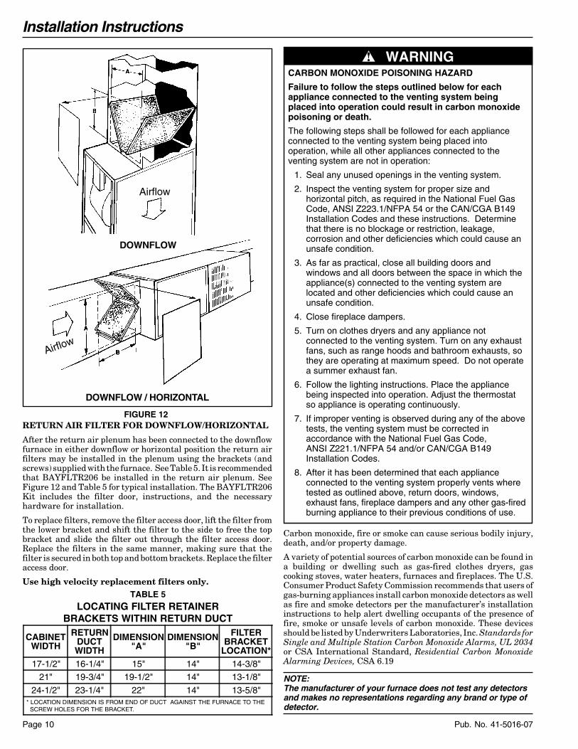
RETURN AIR FILTER FOR DOWNFLOW/HORIZONTAL
After the return air plenum has been connected to the downflowfurnace in either downflow or horizontal position the return airfilters may be installed in the plenum using the brackets (andscrews) supplied with the furnace. See Table 5. It is recommendedthat BAYFLTR206 be installed in the return air plenum. SeeFigure 12 and Table 5 for typical installation. The BAYFLTR206Kit includes the filter door, instructions, and the necessaryhardware for installation.
To replace filters, remove the filter access door, lift the filter fromthe lower bracket and shift the filter to the side to free the topbracket and slide the filter out through the filter access door.Replace the filters in the same manner, making sure that thefilter is secured in both top and bottom brackets. Replace the filteraccess door.
Use high velocity replacement filters only.
Carbon monoxide, fire or smoke can cause serious bodily injury,death, and/or property damage.
A variety of potential sources of carbon monoxide can be found ina building or dwelling such as gas-fired clothes dryers, gascooking stoves, water heaters, furnaces and fireplaces. The U.S.Consumer Product Safety Commission recommends that users ofgas-burning appliances install carbon monoxide detectors as wellas fire and smoke detectors per the manufacturer’s installationinstructions to help alert dwelling occupants of the presence offire, smoke or unsafe levels of carbon monoxide. These devicesshould be listed by Underwriters Laboratories, Inc. Standards forSingle and Multiple Station Carbon Monoxide Alarms, UL 2034or CSA International Standard, Residential Carbon MonoxideAlarming Devices, CSA 6.19
NOTE:The manufacturer of your furnace does not test any detectorsand makes no representations regarding any brand or type ofdetector.
CARBON MONOXIDE POISONING HAZARD
Failure to follow the steps outlined below for each appliance connected to the venting system being placed into operation could result in carbon monoxide poisoning or death.
The following steps shall be followed for each appliance connected to the venting system being placed into operation, while all other appliances connected to the venting system are not in operation:
1. Seal any unused openings in the venting system.
2. Inspect the venting system for proper size and horizontal pitch, as required in the National Fuel Gas Code, ANSI Z223.1/NFPA 54 or the CAN/CGA B149 Installation Codes and these instructions. Determine that there is no blockage or restriction, leakage, corrosion and other deficiencies which could cause an unsafe condition.
3. As far as practical, close all building doors and windows and all doors between the space in which the appliance(s) connected to the venting system are located and other deficiencies which could cause an unsafe condition.
4. Close fireplace dampers.
5. Turn on clothes dryers and any appliance not connected to the venting system. Turn on any exhaust fans, such as range hoods and bathroom exhausts, so they are operating at maximum speed. Do not operate a summer exhaust fan.
6. Follow the lighting instructions. Place the appliance being inspected into operation. Adjust the thermostat so appliance is operating continuously.
7. If improper venting is observed during any of the above tests, the venting system must be corrected in accordance with the National Fuel Gas Code, ANSI Z221.1/NFPA 54 and/or CAN/CGA B149 Installation Codes.
8. After it has been determined that each appliance connected to the venting system properly vents where tested as outlined above, return doors, windows, exhaust fans, fireplace dampers and any other gas-fired burning appliance to their previous conditions of use.
▲ WARNING!
FIGURE 12
Airflow
Airflow
DOWNFLOW
DOWNFLOW / HORIZONTAL
TABLE 5LOCATING FILTER RETAINER
BRACKETS WITHIN RETURN DUCT
CABINETWIDTH
RETURNDUCTWIDTH
DIMENSION"A"
DIMENSION"B"
FILTERBRACKET
LOCATION*17-1/2" 16-1/4" 15" 14" 14-3/8"
21" 19-3/4" 19-1/2" 14" 13-1/8"
24-1/2" 23-1/4" 22" 14" 13-5/8" * LOCATION DIMENSION IS FROM END OF DUCT AGAINST THE FURNACE TO THE SCREW HOLES FOR THE BRACKET.
Installation Instructions
Page 11Pub. No. 41-5016-07
VENTING MATERIALS
THIS FURNACE MUST BE VENTED TO THE OUTDOORS.
THESE FURNACES ARE INDUCED DRAFT VENTED ANDMUST NOT BE CONNECTED TO ANY VENT SERVING AN-OTHER APPLIANCE. PLEASE NOTE THAT THESE FUR-NACES USE POSITIVE-PRESSURE VENT SYSTEMS.
Proper venting is essential to obtain maximum efficiency from acondensing furnace. Proper installation of the vent system isnecessary to assure drainage of the condensate and preventdeterioration of the vent system.
American Gas Association has certified the design of condensingfurnaces for a minimum of 0" clearance from combustible mate-rials with a single wall plastic vent pipe.
The recommended system is assembled from 2", 2-1/2", or 3" plas-tic pipe and fittings (See Table 7, page 14). Where the system isrouted to the outdoors through an existing masonry chimneycontaining flue products from another gas appliance, or whererequired by local codes, then 3" venting of Type 29-4C stainlesssteel must be used in place of PVC material.
These furnaces have been classified as CATEGORY IV furnacesin accordance with the latest edition of ANSI Z21.47 • CAN/CGA-2.3 Standards. Category IV furnaces operate with positive ventpressure and with a vent gas temperature less than 140° F abovethe dewpoint. These conditions require special venting systems,which must be gas tight and water tight.
NOTE:When an existing furnace is removed from a venting systemserving other gas appliances, the venting system is likely to betoo large to properly vent the remainingattached appliances.
The following steps shall be followed with each appliance remain-ing connected to the common venting system placed in operation,while the other appliances remaining connected to the commonventing system are not in operation.
1. Seal any unused openings in the common venting system.
2. Visually inspect the venting system for proper size andhorizontal pitch and determine there is no blockage or restriction,leakage, corrosion or other deficiencies which could cause anunsafe condition.
3. Insofar as is practical, close all building doors and windowsand all doors between the space in which the appliances remainingconnected to the common venting system are located and otherspaces of the building. Turn on clothes dryers and any appliancesnot connected to the common venting system. Turn on any exhaustfans, such as range hoods and bathroom exhausts, so they willoperate at maximum speed. Do not operate a summer exhaust fan,close fireplace dampers.
4. Follow the lighting instructions. Place the appliance beinginspected in operation. Adjust thermostat so appliance will oper-ate continuously.
5. Test for spillage at the draft hood relief opening after 5 min-utes of main burner operation. Use the flame of a match or candle,or smoke from a cigarette, cigar, or pipe.
6. After it has been determined that each appliance remainingconnected to the common venting system properly vents whentested as outlined above, return door, windows, exhaust fans,fireplace dampers and any other gas-burning appliance to theirprevious conditions of use.
If improper venting is observed during any of the above tests, theremaining common venting system must be corrected. Correctionof the remaining common vent system should be done by referringto the latest edition of the National Fuel Gas Code (ANSIZ223.1) • CAN/CGA B149.1 Installation Codes or “Exhibit J” ofANSI Z21.47 • CAN/CGA-2.3 Standards. The following are gen-eral steps to be used to correct or resize a remaining vent systemwhen a furnace which may not be common vented is removed fromthe system:
a. Determine the Btu per hour input of all remaining appli-ances attached to the venting system.
b. Determine the diameter, rise, and lateral of the existingventing system, as well as quantity and type of bends.
c. Use the appropriate tables in the latest edition ofthe National Fuel Gas Code (ANSI Z223.1 •CAN/CGA B149.1 Installation Codes or “Exhibit J” ofANSI Z21.47 • CAN/CGA-2.3 Standards. “Exhibit J” in-cludes examples and drawings of typical venting systems.
GENERAL VENTING
PVC VENT FITTING MATERIAL
These fittings are available from your Gas Furnace Distributors.
Straight Pipe Sections, Couplings, 45° Elbows, 60° Elbows, 90°Elbows, Vent or Sanitary Tee, or other necessary fittings may be2", 2½", 3", or 4" diameter. The allowable materials are shown inTable 7. A vent screen is optional, but recommended. The ventscreen must be 3/8" open mesh weave (minimum 70% open), madeof any non-corrosive material having at least 3/8" open meshweave.
VENT FITTING MATERIAL – PLASTIC
Gas and liquid tight single wall vent fittings, designed for resis-tance to corrosive flue condensate, MUST be used throughout.
Listed in Table 8 & 9 are 2", 2½", 3", and 4" size fittings that meetthese requirements. The materials listed are various grades ofPVC and ABS plastic.
PIPE JOINTS: All joints must be fastened and sealed to preventescape of combustion products into the building.
IMPORTANT:These furnaces may be installed as Direct Vent (sealed combus-tion) or as Nondirect vent (single pipe). The furnaces are shippedDIRECT VENT with sealed combustion.
For DIRECT VENT APPLICATION: The furnaces must be vented tothe exterior of the house and combustion air MUST come throughthe inlet air pipe FROM OUTSIDE AIR.
For NONDIRECT VENT APPLICATION: The furnace shall bevented to the exterior of the house, but combustion air may enterfrom the surrounding area as long as combustion air requirementsare met. (See AIR FOR COMBUSTION AND VENTILATION)
IMPORTANT:
Products installed in Canada must use vent systems that are certi-fied to the Standard for Type BH Gas Venting Systems (ULC S636)for Class II-A venting systems (up to 65°C). Components of thevent system must not be interchanged with other vent systems orunlisted pipe or fittings. Plastic components, specified primers,and glues must be from a single system manufacturer and not in-termixed with other system manufacturer's vent system parts. Inaddition, the first three feet of the vent pipe must be visible for in-spection.

Installation Instructions
Pub. No. 41-5016-07Page 12
IMPORTANT:
The Commonwealth of Massachusetts requires compliancewith regulation 248 CMR 4.00 and 5.00 for installation ofthrough – the – wall vented gas appliances as follows:
For all side wall horizontally vented gas fueled equipmentinstalled in every dwelling, building or structure used inwhole or in part for residential purposes, including thoseowned or operated by the Commonwealth and where the sidewall exhaust vent termination is less than seven (7) feetabove finished grade in the area of the venting, including butnot limited to decks and porches, the following requirementsshall be satisfied:1. INSTALLATION OF CARBON MONOXIDEDETECTORS. At the time of installation of the side wallhorizontal vented gas fueled equipment, the installingplumber or gasfitter shall observe that a hard wired carbonmonoxide detector with an alarm and battery back-up isinstalled on the floor level where the gas equipment is to beinstalled. In addition, the installing plumber or gasfittershall observe that a battery operated or hard wired carbonmonoxide detector with an alarm is installed on eachadditional level of the dwelling, building or structure servedby the side wall horizontal vented gas fueled equipment. Itshall be the responsibility of the property owner to secure theservices of qualified licensed professionals for theinstallation of hard wired carbon monoxide detectorsa. In the event that the side wall horizontally ventedgas fueled equipment is installed in a crawl space or an attic,the hard wired carbon monoxide detector with alarm andbattery back-up may be installed on the next adjacent floorlevel.b. In the event that the requirements of thissubdivision can not be met at the time of completion ofinstallation, the owner shall have a period of thirty (30) daysto comply with the above requirements; provided, however,that during said thirty (30) day period, a battery operatedcarbon monoxide detector with an alarm shall be installed.2. APPROVED CARBON MONOXIDE DETECTORS.Each carbon monoxide detector as required in accordancewith the above provisions shall comply with NFPA 720 andbe ANSI/UL 2034 listed and IAS certified.3. SIGNAGE. A metal or plastic identification plateshall be permanently mounted to the exterior of the buildingat a minimum height of eight (8) feet above grade directly inline with the exhaust vent terminal for the horizontallyvented gas fueled heating appliance or equipment. The signshall read, in print size no less than one-half (1/2) inch insize, “GAS VENT DIRECTLY BELOW. KEEP CLEAR OFALL OBSTRUCTIONS”.
4. INSPECTION. The state or local gas inspector of theside wall horizontally vented gas fueled equipment shall notapprove the installation unless, upon inspection, the inspectorobserves carbon monoxide detectors and signage installed inaccordance with the provisions of 248 CMR 5.08(2)(a)1through 4.This appliance requires a special venting system. IfBAYAIR30AVENTA or BAYVENT200B are used, a copy of theinstallation instructions for the kit shall remain with theappliance or equipment at the completion of installation. Theventing system installation instructions can be obtained fromthe manufacturer by writing to the following address:
American Standard, Inc.6200 Troup HighwayTyler, TX 75707Attention: Manager of Field Operations Excellence
Installation Instructions
Page 13Pub. No. 41-5016-07
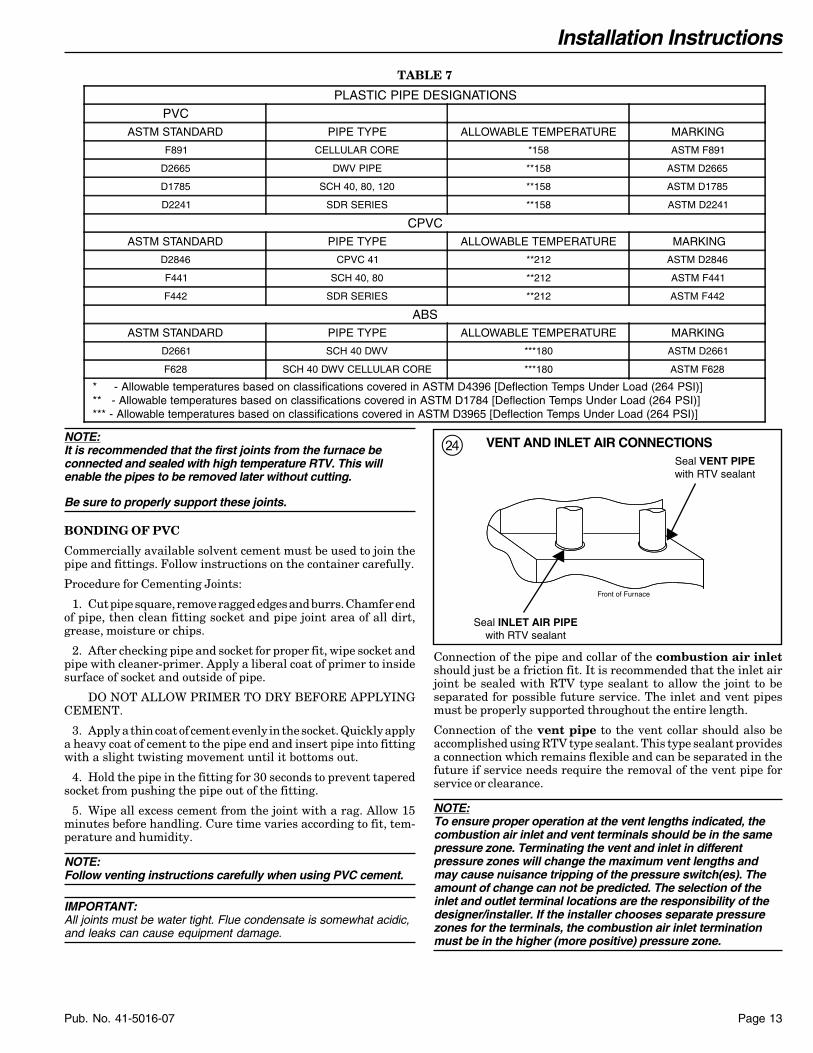
NOTE:It is recommended that the first joints from the furnace beconnected and sealed with high temperature RTV. This willenable the pipes to be removed later without cutting.
Be sure to properly support these joints.
BONDING OF PVC
Commercially available solvent cement must be used to join thepipe and fittings. Follow instructions on the container carefully.
Procedure for Cementing Joints:
1. Cut pipe square, remove ragged edges and burrs. Chamfer endof pipe, then clean fitting socket and pipe joint area of all dirt,grease, moisture or chips.
2. After checking pipe and socket for proper fit, wipe socket andpipe with cleaner-primer. Apply a liberal coat of primer to insidesurface of socket and outside of pipe.
DO NOT ALLOW PRIMER TO DRY BEFORE APPLYINGCEMENT.
3. Apply a thin coat of cement evenly in the socket. Quickly applya heavy coat of cement to the pipe end and insert pipe into fittingwith a slight twisting movement until it bottoms out.
4. Hold the pipe in the fitting for 30 seconds to prevent taperedsocket from pushing the pipe out of the fitting.
5. Wipe all excess cement from the joint with a rag. Allow 15minutes before handling. Cure time varies according to fit, tem-perature and humidity.
NOTE:Follow venting instructions carefully when using PVC cement.
IMPORTANT:All joints must be water tight. Flue condensate is somewhat acidic,and leaks can cause equipment damage.
Connection of the pipe and collar of the combustion air inletshould just be a friction fit. It is recommended that the inlet airjoint be sealed with RTV type sealant to allow the joint to beseparated for possible future service. The inlet and vent pipesmust be properly supported throughout the entire length.
Connection of the vent pipe to the vent collar should also beaccomplished using RTV type sealant. This type sealant providesa connection which remains flexible and can be separated in thefuture if service needs require the removal of the vent pipe forservice or clearance.
NOTE:To ensure proper operation at the vent lengths indicated, thecombustion air inlet and vent terminals should be in the samepressure zone. Terminating the vent and inlet in differentpressure zones will change the maximum vent lengths andmay cause nuisance tripping of the pressure switch(es). Theamount of change can not be predicted. The selection of theinlet and outlet terminal locations are the responsibility of thedesigner/installer. If the installer chooses separate pressurezones for the terminals, the combustion air inlet terminationmust be in the higher (more positive) pressure zone.
Seal VENT PIPEwith RTV sealant
Seal INLET AIR PIPEwith RTV sealant
Front of Furnace
VENT AND INLET AIR CONNECTIONSf
TABLE 7
PLASTIC PIPE DESIGNATIONS
PVCASTM STANDARD PIPE TYPE ALLOWABLE TEMPERATURE MARKING
F891 CELLULAR CORE *158 ASTM F891
D2665 DWV PIPE **158 ASTM D2665
D1785 SCH 40, 80, 120 **158 ASTM D1785
D2241 SDR SERIES **158 ASTM D2241
CPVCASTM STANDARD PIPE TYPE ALLOWABLE TEMPERATURE MARKING
D2846 CPVC 41 **212 ASTM D2846
F441 SCH 40, 80 **212 ASTM F441
F442 SDR SERIES **212 ASTM F442
ABSASTM STANDARD PIPE TYPE ALLOWABLE TEMPERATURE MARKING
D2661 SCH 40 DWV ***180 ASTM D2661
F628 SCH 40 DWV CELLULAR CORE ***180 ASTM F628
* - Allowable temperatures based on classifications covered in ASTM D4396 [Deflection Temps Under Load (264 PSI)] ** - Allowable temperatures based on classifications covered in ASTM D1784 [Deflection Temps Under Load (264 PSI)] *** - Allowable temperatures based on classifications covered in ASTM D3965 [Deflection Temps Under Load (264 PSI)]
Installation Instructions
Pub. No. 41-5016-07Page 14
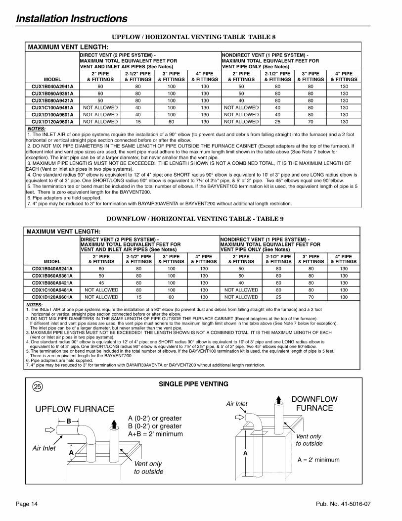
Vent onlyto outside
Air Inlet
AA = 2' minimum
DOWNFLOWFURNACE
Vent onlyto outside
Air Inlet
B
A
A (0-2') or greaterB (0-2') or greaterA+B = 2' minimum
UPFLOW FURNACE
SINGLE PIPE VENTINGg
UPFLOW / HORIZONTAL VENTING TABLE TABLE 8
MAXIMUM VENT LENGTH:
MODEL
DIRECT VENT (2 PIPE SYSTEM) -MAXIMUM TOTAL EQUIVALENT FEET FORVENT AND INLET AIR PIPES (See Notes)
NONDIRECT VENT (1 PIPE SYSTEM) -MAXIMUM TOTAL EQUIVALENT FEET FORVENT PIPE ONLY (See Notes)
2" PIPE& FITTINGS
2-1/2" PIPE& FITTINGS
3" PIPE& FITTINGS
4" PIPE& FITTINGS
2" PIPE& FITTINGS
2-1/2" PIPE& FITTINGS
3" PIPE& FITTINGS
4" PIPE& FITTINGS
CUX1B040A2941A 60 80 100 130 50 80 80 130
CUX1B060A9361A 60 80 100 130 50 80 80 130
CUX1B080A9421A 50 80 100 130 40 80 80 130
CUX1C100A9481A NOT ALLOWED 40 100 130 NOT ALLOWED 40 80 130
CUX1D100A9601A NOT ALLOWED 40 100 130 NOT ALLOWED 40 80 130
CUX1D120A9601A NOT ALLOWED 15 60 130 NOT ALLOWED 25 70 130
NOTES: 1. The INLET AIR of one pipe systems require the installation of a 90° elbow (to prevent dust and debris from falling straight into the furnace) and a 2 foothorizontal or vertical straight pipe section connected before or after the elbow. 2. DO NOT MIX PIPE DIAMETERS IN THE SAME LENGTH OF PIPE OUTSIDE THE FURNACE CABINET (Except adapters at the top of the furnace). Ifdifferent inlet and vent pipe sizes are used, the vent pipe must adhere to the maximum length limit shown in the table above (See Note 7 below forexception). The inlet pipe can be of a larger diameter, but never smaller than the vent pipe. 3. MAXIMUM PIPE LENGTHS MUST NOT BE EXCEEDED! THE LENGTH SHOWN IS NOT A COMBINED TOTAL, IT IS THE MAXIMUM LENGTH OFEACH (Vent or Inlet air pipes in two pipe systems). 4. One standard radius 90° elbow is equivalent to 12' of 4" pipe; one SHORT radius 90° elbow is equivalent to 10' of 3" pipe and one LONG radius elbow isequivalent to 6' of 3" pipe. One SHORT/LONG radius 90° elbow is equivalent to 7½' of 2½" pipe, & 5' of 2" pipe. Two 45° elbows equal one 90°elbow. 5. The termination tee or bend must be included in the total number of elbows. If the BAYVENT100 termination kit is used, the equivalent length of pipe is 5feet. There is zero equivalent length for the BAYVENT200. 6. Pipe adapters are field supplied. 7. 4" pipe may be reduced to 3" for termination with BAYAIR30AVENTA or BAYVENT200 without additional length restriction.
DOWNFLOW / HORIZONTAL VENTING TABLE - TABLE 9
MAXIMUM VENT LENGTH:
MODEL
DIRECT VENT (2 PIPE SYSTEM) -MAXIMUM TOTAL EQUIVALENT FEET FORVENT AND INLET AIR PIPES (See Notes)
NONDIRECT VENT (1 PIPE SYSTEM) -MAXIMUM TOTAL EQUIVALENT FEET FORVENT PIPE ONLY (See Notes)
2" PIPE& FITTINGS
2-1/2" PIPE& FITTINGS
3" PIPE& FITTINGS
4" PIPE& FITTINGS
2" PIPE& FITTINGS
2-1/2" PIPE& FITTINGS
3" PIPE& FITTINGS
4" PIPE& FITTINGS
CDX1B040A9241A 60 80 100 130 50 80 80 130
CDX1B060A9361A 50 80 100 130 50 80 80 130
CDX1B080A9421A 45 80 100 130 40 80 80 130
CDX1C100A9481A NOT ALLOWED 80 100 130 NOT ALLOWED 80 80 130
CDX1D120A9601A NOT ALLOWED 15 60 130 NOT ALLOWED 25 70 130
NOTES: 1. The INLET AIR of one pipe systems require the installation of a 90° elbow (to prevent dust and debris from falling straight into the furnace) and a 2 foot horizontal or vertical straight pipe section connected before or after the elbow. 2. DO NOT MIX PIPE DIAMETERS IN THE SAME LENGTH OF PIPE OUTSIDE THE FURNACE CABINET (Except adapters at the top of the furnace). If different inlet and vent pipe sizes are used, the vent pipe must adhere to the maximum length limit shown in the table above (See Note 7 below for exception). The inlet pipe can be of a larger diameter, but never smaller than the vent pipe. 3. MAXIMUM PIPE LENGTHS MUST NOT BE EXCEEDED! THE LENGTH SHOWN IS NOT A COMBINED TOTAL, IT IS THE MAXIMUM LENGTH OF EACH (Vent or Inlet air pipes in two pipe systems). 4. One standard radius 90° elbow is equivalent to 12' of 4" pipe; one SHORT radius 90° elbow is equivalent to 10' of 3" pipe and one LONG radius elbow is equivalent to 6' of 3" pipe. One SHORT/LONG radius 90° elbow is equivalent to 7½' of 2½" pipe, & 5' of 2" pipe. Two 45° elbows equal one 90°elbow. 5. The termination tee or bend must be included in the total number of elbows. If the BAYVENT100 termination kit is used, the equivalent length of pipe is 5 feet. There is zero equivalent length for the BAYVENT200. 6. Pipe adapters are field supplied. 7. 4" pipe may be reduced to 3" for termination with BAYAIR30AVENTA or BAYVENT200 without additional length restriction.

Installation Instructions
Page 15Pub. No. 41-5016-07
Direct Vent Terminal Clearances
Canadian Installations US Installations
A=Clearance above grade, veranda, porch, deck, orbalcony
12 inches (30 cm) 12 inches (30 cm)
B= Clearance to window or door that may be opened
6 inches (15 cm) for appliances =/< 10,000 Btuh (3 kw), 12inches (30 cm) for appliances > 10,000 Btuh (3 kw) and =/<100,000 Btuh (30 kw), 36 inches (91 cm) for appliances >100,000 Btuh (30 kw)
6 inches (15 cm) for appliances =/< 10,000 Btuh (3 kw), 9inches (23 cm) for appliances > 10,000 Btuh (3 kw) and =/<50,000 Btuh (15 kw), 12 inches (30 cm) for appliances > 50,000Btuh (15 kw)
C= Clearance to permanently closed window * *
D=Vertical clearance to ventilated soffit located above theterminal within a horizontal distance of 2 feet (61 cm)from the center line of the terminal
* *
E= Clearance to unventilated soffit * *
F= Clearance to outside corner * *
G-=
Clearance to inside corner * *
H=Clearance to each side of center line extended abovemeter/regulator assembly
3 feet (91 cm) with a height 15 feet (4.5 m) above themeter/regulator assembly
*
I= Clearance to service regulator vent outlet 3 feet (91 cm) *
J=Clearance to nonmechanical air supply inlet to buildingor the combustion air inlet to any other appliance
6 inches (15 cm) for appliances =/< 10,000 Btuh (3 kw), 12inches (30 cm) for appliances > 10,000 Btuh (3 kw) and =/<100,000 Btuh (30 kw), 36 inches (91 cm) for appliances >100,000 Btuh (30 kw)
6 inches (15 cm) for appliances =/< 10,000 Btuh (3 kw), 9inches (23 cm) for appliances > 10,000 Btuh (3 kw) and =/<50,000 Btuh (15 kw), 12 inches (30 cm) for appliances > 50,000Btuh (15 kw)
K= Clearance to a mechanical air supply inlet 6 feet (1.83m) 3 feet (91 cm) above if within 10 feet (3m) horizontally
L=Clearance above a paved sidewalk or paved drivewaylocated on public property
7 feet (2.13 m) † *
M-=
Clearance under veranda, porch, deck, or balcony `12 inches (30 cm) ‡ *
Notes: 1. In accordance with the current CSA B149.1 Natural Gas and Propane Installation Code. 2. In accordance with the current ANSI Z223.1/NFPA 54 National Fuel Gas Code.†. A vent shall not terminate directly above a sidewalk or paved driveway that is located between two single family dwelling and serves both dwellings.‡. Pemitted only if veranda, porch, deck, or balcony is fully open on a minimum of two sides beneath the floor. * Clearance in accordance with local installation codes and the requirements of the gas supplier and the manufacturer's Installation Instructions.
V
D
EE
V
G
INSIDECORNER DETAIL
BL V
V
FIXED CLOSED
OPERABLE
F
B
C
VFIXED
CLOSEDV
V
VB
B
B
A
X
J
B
H
I
V X
K
M
V VENT TERMINAL X AIR SUPPLY INLET AREA WHERE TERMINAL IS NOT PERMITTED
OPERABLE
h

Installation Instructions
Pub. No. 41-5016-07Page 16
Non-Direct Vent Terminal Clearances
Canadian Installations US Installations
A=Clearance above grade, veranda, porch, deck, orbalcony
12 inches (30 cm) 12 inches (30 cm)
B= Clearance to window or door that may be opened
6 inches (15 cm) for appliances =/< 10,000 Btuh (3 kw), 12inches (30 cm) for appliances > 10,000 Btuh (3 kw) and =/<100,000 Btuh (30 kw), 36 inches (91 cm) for appliances >100,000 Btuh (30 kw)
4 feet (1.2m) below or to the side of opening; 1 foot (0.3m)above opening.
C= Clearance to permanently closed window * *
D=Vertical clearance to ventilated soffit located above theterminal within a horizontal distance of 2 feet (61 cm)from the center line of the terminal
* *
E= Clearance to unventilated soffit * *
F= Clearance to outside corner * *
G= Clearance to inside corner * *
H=Clearance to each side of center line extended abovemeter/regulator assembly
3 feet (91 cm) with a height 15 feet (4.5 m) above themeter/regulator assembly
*
I= Clearance to service regulator vent outlet 3 feet (91 cm) *
J=Clearance to nonmechanical air supply inlet to buildingor the combustion air inlet to any other appliance
6 inches (15 cm) for appliances =/< 10,000 Btuh (3 kw), 12inches (30 cm) for appliances > 10,000 Btuh (3 kw) and =/<100,000 Btuh (30 kw), 36 inches (91 cm) for appliances >100,000 Btuh (30 kw)
4 feet (1.2 m) below or to side of opening; 1 foot (300 m) aboveopening
K= Clearance to a mechanical air supply inlet 6 feet (1.83m) 3 feet (91 cm) above if within 10 feet (3m) horizontally
L=Clearance above a paved sidewalk or paved drivewaylocated on public property
7 feet (2.13 m) † 7 feet (2.13 m)
M= Clearance under veranda, porch, deck, or balcony `12 inches (30 cm) ‡ *
Notes: 1. In accordance with the current CSA B149.1 Natural Gas and Propane Installation Code. 2. In accordance with the current ANSI Z223.1/NFPA 54 National Fuel Gas Code.†. A vent shall not terminate directly above a sidewalk or paved driveway that is located between two single family dwelling and serves both dwellings.‡. Pemitted only if veranda, porch, deck, or balcony is fully open on a minimum of two sides beneath the floor. * Clearance in accordance with local installation codes and the requirements of the gas supplier and the manufacturer's Installation Instructions.
POSSIBLE CONFIGURATIONS FOR TWO PIPE VENTING SYSTEMS
ELBOW AND TEE MUSTBE AS CLOSE TO-GETHERAS POSSIBLE
j

Installation Instructions
Page 17Pub. No. 41-5016-07
HORIZONTAL VENTINGNOTE:Vent termination kit BAYAIR30AVENTA or BAYVENT200* maybe used instead of the horizontal and vertical terminationoptions shown in the following figures.
▲ CAUTION!When the vent pipe is exposed to temperatures below freezing,i.e., when it passes through unheated spaces, etc., the pipemust be insulated with 1/2 inch (22.7 mm) thick Armaflex-typeinsulation or equal. If the space is heated sufficiently to preventfreezing, then the insulation would not be required. If domesticwater pipes are not protected from freezing then it is assumedthe space meets the condition of a heated space.
HORIZONTAL VENTING THROUGH WALL
These furnaces may be installed as direct vent (as shipped)or as nondirect vent. Installation must conform to national,state, and local codes.
The vent & inlet terminals must be located at least 12" minimumabove normally expected snow accumulation level.
Avoid areas where staining or condensate drippage may be aproblem.
Location of the vent/wind terminal should be chosen to meet therequirements of Figure 26 for either direct or non-direct ventapplications.
PITCH – Venting through the wall must maintain 1/4" per footpitched upward to insure that condensate drains back to thefurnace.
FLUE GAS DEGRADATION – The moisture content of the fluegas may have a detrimental effect on some building materials.This can be avoided by using the roof or chimney terminal, ventingoption. When wall venting is used on any surface that can beaffected by this moisture, it is recommended that a corrosionresistant shield (24 inches square) be used behind the ventterminal. This shield can be wood, plastic, sheet metal, etc. Also,silicone caulk all cracks, seams and joints within 3 feet of the vent.
COMBUSTIBLE MATERIAL WALL
A minimum clearance of 1" to combustible materials must bemaintained when using single wall stainless steel venting. SeeFigure 30.
Shield material to be a minimum of 24 gauge stainless or alumi-nized sheet metal. Minimum dimensions are 12"x12". Shieldmust be fastened to both inside and outside of wall. Use screws oranchor type fasteners suited to the outside or inside wall surfaces.
VENT
COMBUSTIONAIR
VENT
VENTPLATE
VENTCAP
12" MINIMUMTO OVERHANG
MAINTAIN 12" (18" FOR CANADA) MINIMUMCLEARANCE ABOVE HIGHEST ANTICIPATED
SNOW LEVEL OR GRADE WHICHEVER IS GREATER
SCREWS(4 req.)
ANCHORS(4 req.)
7.2"
3.2"
BAYVENT200B
k
BAYAIR30AVENTA(Sidewall)
l
;
z
Installation Instructions
Pub. No. 41-5016-07Page 18
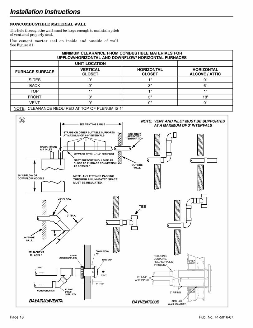
MINIMUM CLEARANCE FROM COMBUSTIBLE MATERIALS FORUPFLOW/HORIZONTAL AND DOWNFLOW/ HORIZONTAL FURNACES
UNIT LOCATION
FURNACE SURFACE VERTICALCLOSET
HORIZONTALCLOSET
HORIZONTALALCOVE / ATTIC
SIDES 0" 1" 0"BACK 0" 3" 6"TOP 1" 1" 1"
FRONT 3" 3" 18"VENT 0" 0" 0"
NOTE: CLEARANCE REQUIRED AT TOP OF PLENUM IS 1"
NOTE: VENT AND INLET MUST BE SUPPORTEDAT A MAXIMUM OF 3' INTERVALS
40" UPFLOW ORDOWNFLOW MODELS
SEE VENTING TABLE
OUTSIDEWALL
NOTE: ANY FITTINGS PASSINGTHROUGH AN UNHEATED SPACEMUST BE INSULATED.
FIRST SUPPORT SHOULD BE ASCLOSE TO FURNACE CONNECTIONAS POSSIBLE.
UPWARD PITCH -- 1/4" PER FOOT
STRAPS OR OTHER SUITABLE SUPPORTSAT MAXIMUM OF 3'-0" INTERVALS
COMBUSTIONAIR INLET
USE ONLYAPPROVED
TERMINATION
TEE
RAIN CAP
COMBUSTION AIR
STRAP(FIELD SUPPLIED)
COMBUSTIONAIR
VENT
ELBOW(FIELD SUPPLIED)
VENT
1" + 1/2"
BAYAIR30AVENTA
3" PIPING3" PIPING
2", 2-1/2"or 3" PIPING
REDUCING COUPLING,FIELD SUPPLIEDIF NEEDEDIF NEEDED
SEAL ALLWALL CAVITIES
BAYVENT200B
x
NONCOMBUSTIBLE MATERIAL WALL
The hole through the wall must be large enough to maintain pitchof vent and properly seal.
Use cement mortar seal on inside and outside of wall.See Figure 31.

Installation Instructions
Page 19Pub. No. 41-5016-07
vSUPPORT HORIZONTAL PIPE EVERY 3'0" WITH THE FIRST SUPPORT AS CLOSETO THE FURNACE AS POSSIBLE.INDUCED DRAFT BLOWER, HOUSING,AND FURNACE MUST NOT SUPPORTTHE WEIGHT OF THE FLUE PIPE.
b
6" Min.
40 Inch Upflow or Downflow Furnace
Slope 1/4" per ft.
Slope 1/4" per ft.
All horizontal pipes must besupported at a maximum of 3
foot intervals
DOWNWARD VENTINGFurnace may be in vertical or horizontal configuration.
c
NOTES:A) Condensate trap for vent pipe must be a minimum of 6 inches in height.B) Condensate trap for vent and inlet pipe must be connected into a condensate drain pump; an open or
vented drain; or it can be connected to the outlet hose of the furnace's condensate trap. Outdoor drain-ing of the furnace and coil condensate is permissible if allowed by local codes. Caution should be takento prevent drains from freezing or causing slippery conditions that could lead to personal injury. Exces-sive draining of condensate may cause saturated ground conditions that may result in damage to plants.
C) The condensate trap should be primed at initial start up prior to heating season operation.
DOWNWARD VENT LENGTH ISLIMITED TO A MAXIMUM OF 15
EQUIVALENT FEET.
Installation Instructions
Pub. No. 41-5016-07Page 20
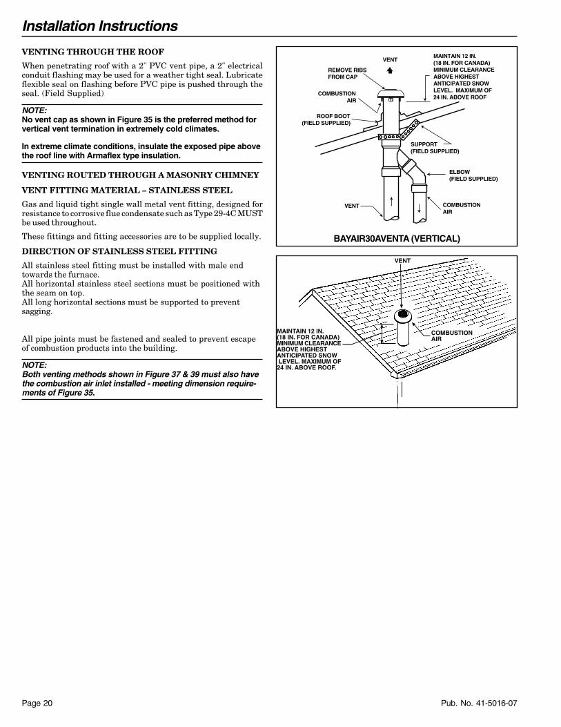
VENTING THROUGH THE ROOF
When penetrating roof with a 2" PVC vent pipe, a 2" electricalconduit flashing may be used for a weather tight seal. Lubricateflexible seal on flashing before PVC pipe is pushed through theseal. (Field Supplied)
NOTE:No vent cap as shown in Figure 35 is the preferred method forvertical vent termination in extremely cold climates.
In extreme climate conditions, insulate the exposed pipe abovethe roof line with Armaflex type insulation.
VENTING ROUTED THROUGH A MASONRY CHIMNEY
VENT FITTING MATERIAL – STAINLESS STEEL
Gas and liquid tight single wall metal vent fitting, designed forresistance to corrosive flue condensate such as Type 29-4C MUSTbe used throughout.
These fittings and fitting accessories are to be supplied locally.
DIRECTION OF STAINLESS STEEL FITTING
All stainless steel fitting must be installed with male endtowards the furnace.All horizontal stainless steel sections must be positioned withthe seam on top.All long horizontal sections must be supported to preventsagging.
All pipe joints must be fastened and sealed to prevent escapeof combustion products into the building.
NOTE:Both venting methods shown in Figure 37 & 39 must also havethe combustion air inlet installed - meeting dimension require-ments of Figure 35.
BAYAIR30AVENTA (VERTICAL)
REMOVE RIBSFROM CAP
COMBUSTION AIR
ROOF BOOT(FIELD SUPPLIED)
COMBUSTIONAIR
VENT
ELBOW(FIELD SUPPLIED)
MAINTAIN 12 IN.(18 IN. FOR CANADA)MINIMUM CLEARANCEABOVE HIGHEST ANTICIPATED SNOWLEVEL. MAXIMUM OF24 IN. ABOVE ROOF
SUPPORT(FIELD SUPPLIED)
VENT
MAINTAIN 12 IN.(18 IN. FOR CANADA)MINIMUM CLEARANCEABOVE HIGHESTANTICIPATED SNOW LEVEL. MAXIMUM OF24 IN. ABOVE ROOF.
VENT
COMBUSTIONAIR

Installation Instructions
Page 21Pub. No. 41-5016-07
n
SUPPORT THE SINGLE WALSTAINLESS STEEL GASVENTING AND CENTER IT INTHE CHIMNEY OPENING WITANGLES AS SHOWN OR ANOTHER EQUIVALENTMANNER.
NOTE:HORIZONTAL VENTINGTO VERTICAL VENTING
6 IN. MIN.EE CAUTION
STAINLESSSTEELVENT CAP
TYPE 29-4C STAINLESS STEEL VENTING -USED THROUGH CHIMNEY THAT VENTS
ANOTHER GAS APPLIANCESTAINLESS STEEL
VENT CAP(OPTIONAL)
▲ CAUTION!Do not run vent through chimney for wood burning or oilfurnaces or incinerators.
If remaining free area between single wall flue pipe andmasonry chimney is to be used for another gas appli-ance venting area must be sufficient to vent that appli-ance and that appliance must be connected to chimneywith separate entry openings.
IMPORTANT –The single wall flue pipe joints must be sealed.The 90° elbow connection to vertical pipe must be sealed toprevent condensate leakage to base of masonry chimney.
m
▲ CAUTION!Do not run vent through chimney for wood burning oroil furnaces or incinerators or any other gas appliance.
IMPORTANT –The single wall flue pipe joints must be sealed.
The 90° elbow connection to vertical pipe must be sealed toprevent condensate leakage to base of masonry chimney.
PVC PLASTIC VENTING - ONLYTHROUGH UNUSED CHIMNEY.
SUPPORT THE SINGLEWALL FLUE PIPE AND CENTER IT IN THE CHIMNEY OPENING WIANGLES AS SHOWN OANOTHER EQUIVALENMANNER.
NOTE:HORIZONTAL VENTING TO VERTICAL VENTING
6 IN. MIN.
STAINLESSSTEELVENT CAP
SEE CAUTION
FLUE PIPE
COUPLINGAS REQUIRED
FLUE PIPE
OUPLING TO SUPPORT PE FROM ANGLES R OTHER SUITABLEUPPORT METHOD
STAINLESS STEELVENT CAP
(OPTIONAL)
,
GALVANIZED FIRESTOP SHOULDBE FABRICATED WITH 3-7/8" DIA.HOLE FOR SUPPORT FLANGE(12" x 12" PANEL OR 12" DIA MIN.)
VENTING THROUGH CEILING
CEILING
SUPPORTFLANGE
FLUE PIPE
COUPLING
SEAL BETWEEN FLANGE, PIPE,COUPLING AND METAL PANELWITH HI TEMP RTV SILICONE SEALANT
CLEARANCE ( 0" ACCEPTABLE FOR PVC VENT PIPE )( 1" ACCEPTABLE FOR TYPE 29-4C STAINLESS STEEL VENT PIPE )
Installation Instructions
Pub. No. 41-5016-07Page 22
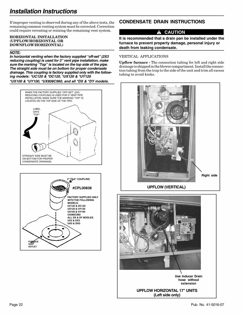
CONDENSATE DRAIN INSTRUCTIONS
▲▲ CAUTION!It is recommended that a drain pan be installed under thefurnace to prevent property damage, personal injury ordeath from leaking condensate.
VERTICAL APPLICATIONS
Upflow furnace - The connection tubing for left and right sidedrainage is shipped in the blower compartment. Install the connec-tion tubing from the trap to the side of the unit and trim all excesstubing to avoid kinks.
UPFLOW HORIZONTAL 17" UNITS(Left side only)
Use Inducer Drainhose without
extension
UPFLOW (VERTICAL)
Right side
If improper venting is observed during any of the above tests, theremaining common venting system must be corrected. Correctioncould require rerouting or resizing the remaining vent system.
HORIZONTAL INSTALLATION(UPFLOW/HORIZONTAL ORDOWNFLOW/HORIZONTAL)
NOTE:In horizontal venting when the factory supplied “off-set” (2X3reducing coupling) is used for 3” vent pipe installation, makesure the marking “Top” is located on the top side of the pipe.The straight side must be on bottom for proper condensatedrainage. This coupling is factory supplied only with the follow-ing models: *UC120 & *DC120, *UX120 & *UY120*UX100 & *UY100, *UX808C960, and all *DX & *DY models.
2" TO 3" COUPLING
FURNACE VENT OUTLET
FACTORY SUPPLIED ONLY WITH THE FOLLOWING MODELS:UC120 & DC120UX120 & UY120UX100 & UY100UX080C960ALL DX & DY MODLESUX3 & DX3UH3 & DH3
#CPL00838
LABEL SAYS "TOP"
STRAIGHT SIDE MUST BE ON BOTTOM FOR PROPER CONDENSATE DRAINAGE.
WHEN THE FACTORY SUPPLIED "OFF-SET" (2X3 REDUCING COUPLING) IS USED FOR 3" VENT PIPE INSTALLATION, MAKE SURE THE MARKING "TOP" IS LOCATED ON THE TOP SIDE OF THE PIPE.
Installation Instructions
Page 23Pub. No. 41-5016-07
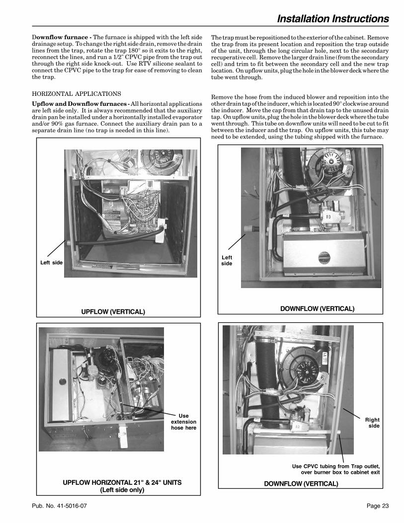
The trap must be repositioned to the exterior of the cabinet. Removethe trap from its present location and reposition the trap outsideof the unit, through the long circular hole, next to the secondaryrecuperative cell. Remove the larger drain line (from the secondarycell) and trim to fit between the secondary cell and the new traplocation. On upflow units, plug the hole in the blower deck where thetube went through.
Remove the hose from the induced blower and reposition into theother drain tap of the inducer, which is located 90° clockwise aroundthe inducer. Move the cap from that drain tap to the unused draintap. On upflow units, plug the hole in the blower deck where the tubewent through. This tube on downflow units will need to be cut to fitbetween the inducer and the trap. On upflow units, this tube mayneed to be extended, using the tubing shipped with the furnace.
Downflow furnace - The furnace is shipped with the left sidedrainage setup. To change the right side drain, remove the drainlines from the trap, rotate the trap 180° so it exits to the right,reconnect the lines, and run a 1/2" CPVC pipe from the trap outthrough the right side knock-out. Use RTV silicone sealant toconnect the CPVC pipe to the trap for ease of removing to cleanthe trap.
HORIZONTAL APPLICATIONS
Upflow and Downflow furnaces - All horizontal applicationsare left side only. It is always recommended that the auxiliarydrain pan be installed under a horizontally installed evaporatorand/or 90% gas furnace. Connect the auxiliary drain pan to aseparate drain line (no trap is needed in this line).
DOWNFLOW (VERTICAL)
Leftside
Useextensionhose here
UPFLOW HORIZONTAL 21" & 24" UNITS(Left side only)
UPFLOW (VERTICAL)
Left side
Use CPVC tubing from Trap outlet,over burner box to cabinet exit
DOWNFLOW (VERTICAL)
Rightside

Installation Instructions
Pub. No. 41-5016-07Page 24
Primary drain vent stackmust terminate belowsecondary heat exchangercondensate drain outlet.
To drain opening
If upflow furnace is installedover a finished ceiling, overflowfrom the primary drain ventstack must flow into an auxillarydrain pan to prevent damage tothe finished ceiling below.
Cut off curved end ofInducer drain hose
DOWNFLOW (HORIZONTAL)
Connections must be made to an OPEN/VENTED DRAIN.Outdoor draining of the furnace and coil condensate is permis-sible if allowed by local codes. Caution should be taken to preventdrains from freezing or causing slippery conditions that could leadto personal injury. Excessive draining of condensate may causesaturated ground conditions that may result in damage to plants.
NOTE:Use 1/2" or larger PVC or CPVC pipe and fittings as requiredfor drain connections (fittings, pipe and solvent cement notprovided).
NOTE:A corrosion resistant condensate pump must be used if apump is required for a specific drain system.
IMPORTANT:The condensate drain should be installed with provisions toprevent winter freeze-up of the condensate drain line. Frozencondensate will block drains, resulting in furnace shutdown. If thedrain line cannot be installed in a conditioned space, then ULlisted heat tape should be applied as required to prevent freezing(per manufacturer’s instructions). The heat tape should be rated at5 or 6 watts per foot at 120 volts. Self-regulating (preferred) orthermostatically controlled heat tape is required.
Evaporator and furnace condensate drain piping may bemanifolded together. A primary drain vent stack must be in-stalled and terminated below the outlet of the secondary heatexchanger drain connection to prevent water from damagingfurnace controls if the primary drain outlet plugs up. Where thefurnace is installed above a finished ceiling, the primary drainvent stack must be installed such that overflow from the ventstack opening will flow into an axillary drain pan in order toprevent water damage to the finished ceiling below.
Installation Instructions
Page 25Pub. No. 41-5016-07
^
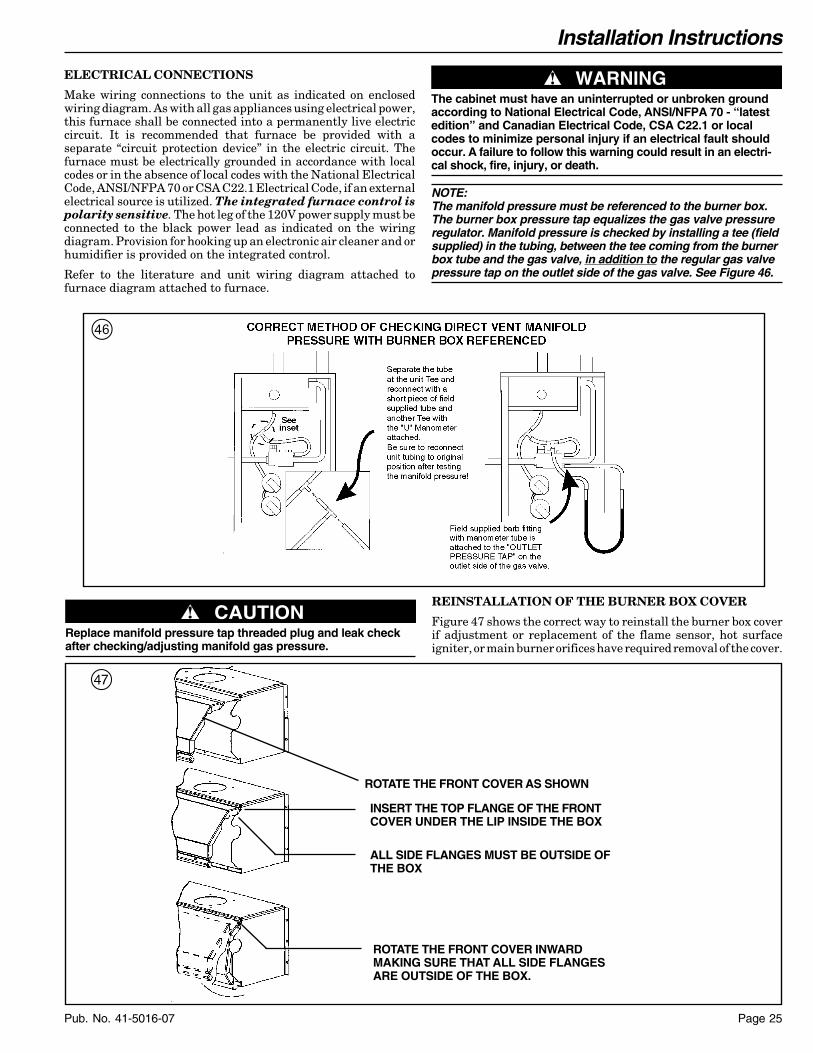
NOTE:The manifold pressure must be referenced to the burner box.The burner box pressure tap equalizes the gas valve pressureregulator. Manifold pressure is checked by installing a tee (fieldsupplied) in the tubing, between the tee coming from the burnerbox tube and the gas valve, in addition to the regular gas valvepressure tap on the outlet side of the gas valve. See Figure 46.
ELECTRICAL CONNECTIONS
Make wiring connections to the unit as indicated on enclosedwiring diagram. As with all gas appliances using electrical power,this furnace shall be connected into a permanently live electriccircuit. It is recommended that furnace be provided with aseparate “circuit protection device” in the electric circuit. Thefurnace must be electrically grounded in accordance with localcodes or in the absence of local codes with the National ElectricalCode, ANSI/NFPA 70 or CSA C22.1 Electrical Code, if an externalelectrical source is utilized. The integrated furnace control ispolarity sensitive. The hot leg of the 120V power supply must beconnected to the black power lead as indicated on the wiringdiagram. Provision for hooking up an electronic air cleaner and orhumidifier is provided on the integrated control.
Refer to the literature and unit wiring diagram attached tofurnace diagram attached to furnace.
▲ WARNING!The cabinet must have an uninterrupted or unbroken groundaccording to National Electrical Code, ANSI/NFPA 70 - “latestedition” and Canadian Electrical Code, CSA C22.1 or localcodes to minimize personal injury if an electrical fault shouldoccur. A failure to follow this warning could result in an electri-cal shock, fire, injury, or death.
▲ CAUTION!Replace manifold pressure tap threaded plug and leak checkafter checking/adjusting manifold gas pressure.
REINSTALLATION OF THE BURNER BOX COVER
Figure 47 shows the correct way to reinstall the burner box coverif adjustment or replacement of the flame sensor, hot surfaceigniter, or main burner orifices have required removal of the cover.
&
ROTATE THE FRONT COVER INWARDMAKING SURE THAT ALL SIDE FLANGESARE OUTSIDE OF THE BOX.
INSERT THE TOP FLANGE OF THE FRONTCOVER UNDER THE LIP INSIDE THE BOX
ALL SIDE FLANGES MUST BE OUTSIDE OFTHE BOX
ROTATE THE FRONT COVER AS SHOWN
Installation Instructions
Pub. No. 41-5016-07Page 26
OUTDOOR UNIT (NO TRANSFORMER)
SEE NOTE 5
From Dwg. B340432 Rev. 2
SEE NOTE 7
FURNACE
B/C B/C
TO 115 V 1 PH.,60 HZ., POWERSUPPLY PERLOCAL CODES
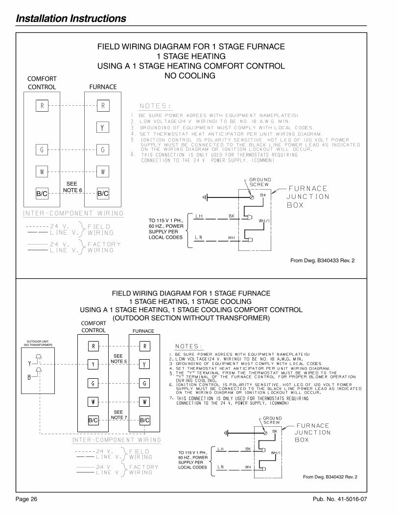
FIELD WIRING DIAGRAM FOR 1 STAGE FURNACE1 STAGE HEATING, 1 STAGE COOLING
USING A 1 STAGE HEATING, 1 STAGE COOLING COMFORT CONTROL(OUTDOOR SECTION WITHOUT TRANSFORMER)
COMFORTCONTROL
FIELD WIRING DIAGRAMS
From Dwg. B340433 Rev. 2
SEE NOTE 6
B/C B/C
TO 115 V 1 PH.,60 HZ., POWERSUPPLY PERLOCAL CODES
FIELD WIRING DIAGRAM FOR 1 STAGE FURNACE1 STAGE HEATING
USING A 1 STAGE HEATING COMFORT CONTROLNO COOLING COMFORT
CONTROL FURNACE

Installation Instructions
Page 27Pub. No. 41-5016-07
▲ WARNING!FIRE OR EXPLOSION HAZARD
Failure to follow the safety warnings exactly could result inserious injury, death or property damage.
Never test for gas leaks with an open flame. Use a commer-cially available soap solution made specifically for the detec-tion of leaks to check all connections. A fire or explosion mayresult causing property damage, personal injury, or loss of life.
GAS PIPING
The upflow/horizontal furnace is shipped standard for left sideinstallation of gas piping. A knockout is provided on the right sidefor an alternate gas piping arrangement. See Figure 32.
The installation of piping shall be in accordance with piping codesand the regulations of the local gas company. Pipe joint compoundmust be resistant to the chemical reaction with liquefied petro-leum gases.
Refer to piping Table 8, for delivery sizes. Connect gas supply tothe unit, using a ground joint union and a manual shut-off valveas shown in Figures 32 & 33. National codes require a condensa-tion drip leg to be installed ahead of the controls as shown inFigures 32 & 33.
The furnace and its individual shut-off valve must be discon-nected from the gas supply piping system during any pressuretesting of that system at test pressures in excess of 1/2 psig(3.5 kPa).
The furnace must be isolated from the gas supply piping by closingits individual manual shut-off valve during any pressure testingof the gas supply piping system at test pressures equal to or lessthan 1/2 psig (3.5 kPa).
▲ CAUTION!
Use a backup wrench on the gas valve when installing gaspiping to prevent damage to the gas valve and manifoldassembly.
NOTE:Maximum pressure to the gas valve for natural gas is13.8" W.C. Minimum pressure is 5.0" W.C. Maximumpressure to the gas valve for propane is 13.8" W.C.Minimum pressure is 11.0" W.C.
All gas fittings must be checked for leaks using a soapysolution before lighting the furnace. DO NOT CHECK WITHAN OPEN FLAME!
COMBUSTION AND INPUT CHECK
1. Make sure all gas appliances are off except the furnace.
2. Clock the gas meter with the furnace operating (determine thedial rating of the meter) for one revolution.
3. Match the “Sec” column in the gas flow (in cfh) Table 10 withthe time clocked.
4. Read the “Flow” column opposite the number of secondsclocked.
5. Use the following factors if necessary:For 1 Cu. Ft. Dial Gas Flow CFH = Chart Flow Reading ÷ 2For 1/2 Cu Ft. Dial Gas Flow CFH = Chart Flow Reading ÷ 4For 5 Cu. Ft. Dial Gas Flow CFH = 10X Chart Flow Reading ÷ 4
6. Multiply the final figure by the heating value of the gasobtained from the utility company and compare to the nameplaterating. This must not exceed the nameplate rating.
7. Changes can be made by adjusting the manifold pressure orchanging orifices (orifice change may not always be required). Toadjust the manifold pressure:
a. Turn off all electrical power to the system.
b. Attach a manifold pressure gauge to the outlet pressure tapmarked “OUT PRESS TAP” on White-Rodgers gas valvemodel 36F or boss marked “OUT P” on White-Rodgers gasvalve model 36G. For the gas valve model 36F, measure-ment requires removal of the plug and installation of abarbed fitting. Attach flexible tubing and a manometer tothe barbed fitting.
For the gas valve model 36G, do not remove the pressuretap test screw. Using a 3/32" hex wrench, loosen thepressure tap test screw one turn and install 5/16" flexibletubing and a manometer directly onto the outlet pressureboss.
c. Turn on system power and energize valve.
d. Remove the regulator adjustment screw cap on the gasvalve for manifold pressure adjustment.
e. Turn the adjustment nut clockwise to increase the gas flowrate, and counterclockwise to decrease the gas flow rateusing a 3/32" hex wench.
f. The final manifold pressure setting shall be as specifiedin Table 11 with an input of no more than nameplate ratingand no less than 93% of the nameplate rating, unless theunit is derated for high altitude.
g. Replace the regulator adjustment screw cap and tightensecurely.
h. Turn off all electrical power to the system.
i. Remove the manometer and flexible tubing. Remove thebarbed fitting and replace the plug or tighten the pressuretest screw.
j. Turn on electrical power to the system and energize valve.
k. Using a leak detection solution or soap suds, check forleaks at plug or pressure boss screw.
TABLE 9ORIFICE SIZES
INPUTRATINGBTUH
NUMBEROF
BURNERS
MAIN BURNER ORIFICEDRILL SIZE
NAT. GAS LP GAS
40,00060,00080,000100,000120,000
23456
4545454545
5656565656
TABLE 8NATURAL GAS ONLY
TABLE OF CUBIC FEET PER HOUR OF GASFOR VARIOUS PIPE SIZES AND LENGTHS
PIPESIZE
LENGTH OF PIPE
10 20 30 40 50 60 70
1/2 132 92 73 63 56 50 46
3/4 278 190 152 130 115 105 96
1 520 350 285 245 215 195 180
1-1/4 1050 730 590 520 440 400 370
This table is based on pressure drop of 0.3 inch W.C. and 0.6 SP.GR. gas

Installation Instructions
Pub. No. 41-5016-07Page 28
FIGURE 32
UPFLOW MAY BE LEFT OR RIGHT HAND GAS PIPING
MAIN MANUALSHUT-OFF VALVE
AUTOMATIC GAS VALVEWITH MANUAL SHUT-OFF
GROUNDUNIONJOINT
DRIPLEG
AUTOMATIC GAS VALVEWITH MANUAL SHUT-OFF
MAIN MANUALSHUT-OFF VALVE
GROUNDUNIONJOINT
DRIPLEG
THE DOWNFLOW (VERTICAL) MAY BE INSTALLED LEFT OR RIGHT SIDE GAS PIPING
FIGURE 33
On/Offff SwiSwitchch
White-Rodgers 36F gas valve White-Rodgers 36G gas valve
FIGURE 34
Outlet Pressure BossOutlet Pressure Boss
On/Offff SwiSwitchch
Inlet Pressurelet PressureBoss Boss (opt.).)
RegululatortorAdjAdjustust

Installation Instructions
Page 29Pub. No. 41-5016-07
HIGH ALTITUDE DERATE
Input ratings (BTUH) of these furnaces are based on sea leveloperation and should not be changed at elevations up to 2,000 ft.If the installation is 2,000 ft. or above, the furnace input rate(BTUH) shall be reduced 4% for each 1,000 ft. above sea level. Thefurnace input rate shall be checked by clocking the gas flow rate(CFH) and multiplying by the heating value obtained from thelocal utility supplier for the gas being delivered at the installedaltitude.
Input rate changes can be made by adjusting the manifoldpressure (min 3.0 - max 3.7 in. W.C. - Natural Gas) or changingorifices (orifice change may not always be required). If the desiredinput rate cannot be achieved with a change in manifold pressure,then the orifices must be changed.
LP installations will require an orifice change. See Table 13 forhelp in selecting orifices if orifice change is required.
IMPORTANT:Reinstall the propane orifices to the same depth as the orificessupplied with the equipment.
Furnace input rate and temperature rise should be checked againafter changing orifices to confirm the proper rate for the altitude.
Installations above 4,000 feet may require a pressure switchchange. If required, use the BAYHALT*** Kit (High AltitudeAccessory Kit) listed in PRODUCT DATA.
START-UP AND ADJUSTMENTPRELIMINARY INSPECTIONS
With gas and electrical power “OFF”1. Duct connections are properly sealed.2. Filters are in place.3. Venting is properly assembled.4. Blower door is in place.
Flip the switch on the main gas valve within the unit to the “OFF”position. Turn the external gas valve to “ON”. Purge the air fromthe gas lines. After purging, check all gas connections for leakswith a soapy solution — DO NOT CHECK WITH AN OPENFLAME. Allow 5 minutes for any gas that might have escaped todissipate. LP Gas being heavier than air may require forcedventilation. Flip the switch on the gas valve in the unit to the “ON”position.
TABLE 10GAS FLOW IN CUBIC FEET PER HOUR
2 CUBIC FOOT DIAL
SEC. FLOW SEC. FLOW SEC. FLOW SEC. FLOW8 900 29 248 50 144 82 889 800 30 240 51 141 84 8610 720 31 232 52 138 86 8411 655 32 225 53 136 88 8212 600 33 218 54 133 90 8013 555 34 212 55 131 92 7814 514 35 206 56 129 94 7615 480 36 200 57 126 96 7516 450 37 195 58 124 98 7317 424 38 189 59 122 100 7218 400 39 185 60 120 104 6919 379 40 180 62 116 108 6720 360 41 176 64 112 112 6421 343 42 172 66 109 116 6222 327 43 167 68 106 120 6023 313 44 164 70 103 124 5824 300 45 160 72 100 128 5625 288 46 157 74 97 132 5426 277 47 153 76 95 136 5327 267 48 150 78 92 140 5128 257 49 147 80 90 144 50
TABLE 12PART NUMBERS FOR REPLACEMENT ORIFICESDRILLSIZE
PARTNUMBER
DRILLSIZE
PARTNUMBER
44454647484950
ORF00501ORF00644ORF00909ORF00910ORF01099ORF00503ORF00493
545556575859
ORF00555ORF00693ORF00907ORF00908ORF01338ORF01339
TABLE 13
OrificeTwist Drill
Size IfInstalledAt SeaLevel
ALTITUDE ABOVE SEA LEVEL
and Orifice Required At Other Elevations
2000 3000 4000 5000 6000 7000 8000 9000 10000424344454647
424445464748
434445474748
434445474749
434546474849
444547484849
444647484950
454748494950
464748495051
474850505152
5455565758
5455565859
5555565960
5555575960
5556576061
5556576062
5556586162
5656596263
5656596363
5657606364
From National Fuel Gas Code - Table F-4
▲ CAUTION!Replace and/or tighten all plugs removed or loosened whenadjusting gas pressure. Leak check the fittings before placingthe furnace into regular service. Failure to follow this warningcould result in fire, explosion, or property damage.
Table 9 – page 24, lists the main burner orifices used with thefurnace. If a change of orifices is required to correct the furnaceinput rating refer to Table 12.
TABLE 11
FINAL MANIFOLD PRESSURE SETTINGSFUEL PRESSURE
NATURAL GAS 3.5" W.C.
LP GAS 11.0" W.C.
Installation of this furnace at altitudes above 2,000 ft.(610m) shall be in accordance with the local codes, or in theabsence of local codes, the National Fuel Gas Code, ANSIZ223.1/ NFPA 54 or National Standard of Canada, NaturalGas and Propane Installation Code, CSA 149.1. Installationof this furnace at altitudes above 2,000 ft. (610m) shall bemade in accordance with the listed high Altitude Conver-sion Kit available with this furnace.

Installation Instructions
Pub. No. 41-5016-07Page 30
After the flame sensor confirms that ignition has been achieved,the delay to fan ON period begins timing and after approximately45 seconds the indoor blower motor will be energized and willcontinue to run during the heating cycle.
When the thermostat is satisfied, R and W thermostat contactsopen, the gas valve will close, the flames will extinguish, and theinduced draft blower will be de-energized. The indoor blowermotor will continue to run for the fan off period (Field selectableat 60, 100, 140 or 180 seconds), then will be de-energized by thecontrol module.
CONTROL AND SAFETY SWITCH ADJUSTMENTS
LIMIT SWITCH CHECK OUT
The limit switch is a safety device designed to close the gas valveshould the furnace become overheated. Since proper operation ofthis switch is important to the safety of the unit, it must bechecked out on initial start up by the installer.
To check for proper operation of the limit switches, set the thermo-stat to a temperature higher than the indicated temperature tobring on the gas valve.
Restrict the airflow by blocking the return air (disconnecting theindoor blower may trip the inducer limit). When the furnacereaches the maximum outlet temperature as shown on the ratingplate, the burners must shut off. If they do not shut off after areasonable time and overheating is evident, a faulty limit switchis probable and the limit switch must be replaced. After checkingthe operation of the limit control, be sure to remove the paper orcardboard from the return air inlet. Refer to Service Facts foradditional instructions.
NOTE TO INSTALLER
Review the following warnings with the owner. Review contentsof USER’S INFORMATION MANUAL with the owner.
AIRFLOW ADJUSTMENT
Check inlet and outlet air temperatures to make sure they arewithin the ranges specified on the furnace rating nameplate. If theairflow needs to be increased or decreased, see the wiring diagramfor information on changing the speed of the blower motor.
▲ WARNING!Disconnect power to the unit before removing the blower door.Failure to follow this warning could result in property damage,personal injury or death.
This unit is equipped with a blower door switch which cuts powerto the blower and gas valve causing shutdown when the door isremoved. Operation with the door removed or ajar can permit theescape of dangerous fumes. All panels must be securely closed atall times for safe operation of the furnace.
INDOOR BLOWER TIMING
Heating: The integrated furnace control controls the indoorblower. The blower start is fixed at 45 seconds after ignition. TheFAN-OFF period is field selectable by dip switches at 60, 100, 140,or 180 seconds. The factory setting is 100 seconds (See wiringdiagram).
Cooling: The fan delay off period is factory set at 0 seconds. Theoption for 80 second delay off is field selectable (See wiringdiagram).
ROOM AIR THERMOSTAT HEAT ANTICIPATORADJUSTMENT
Set the thermostat heat anticipator according to the current flowmeasured, or the settings found in the notes on the furnace wiringdiagram (found in the SERVICE FACTS or inside the furnacecasing).
LIGHTING INSTRUCTIONS
▲ WARNING!DO NOT attempt to manually light the burner. Failure to followthis warning could result in property damage, personal injury,or death.
Lighting instructions appear on each unit. Each installation mustbe checked out at the time of initial start up to insure properoperation of all components. Check out should include putting theunit through one complete cycle as outlined below.
Turn on the main electrical supply and set the thermostat abovethe indicated temperature. The ignitor will automatically heat,then the gas valve is energized to permit the flow of gas to theburners. After ignition and flame is established, the flame controlmodule monitors the flame and supplies power to the gas valveuntil the thermostat is satisfied.
To shut off.
For complete shutdown: Flip the switch on the main gas valve tothe “OFF” position (See Figure 34). Disconnect the electricalsupply to the unit.
▲ CAUTION!If this is done during the cold weather months, provisionsmust be taken to prevent freeze-up of all water pipes and waterreceptacles. Failure to follow this warning could result inproperty damage.
Whenever your house is to be vacant, arrange to havesomeone inspect your house for proper temperature. This isvery important during freezing weather. If for any reasonyour furnace should fail to operate damage could result,such as frozen water pipes.
SEQUENCE OF OPERATION
Thermostat call for heat
R and W thermostat contacts close signaling the control moduleto run its self-check routine. After the control module has verifiedthat the pressure switch contacts are open and the limit switch(es)contacts are closed, the draft blower will be energized.
As the induced draft blower comes up to speed, the pressureswitch contacts will close and the ignitor warm up period will begin.The ignitor will heat for approximately 17 seconds, then the gasvalve is energized to permit gas flow to the burners. The flamesensor confirms that ignition has been achieved within the 4second ignition trial period.
▲ WARNING!EXPLOSION HAZARD!PROPANE GAS IS HEAVIER THAN AIR AND MAY COLLECTIN ANY LOW AREAS OR CONFINED SPACES. IN ADDITION,ODORANT FADE MAY MAKE THE GAS UNDETECTABLEEXCEPT WITH A WARNING DEVICE. IF THE GAS FURNACEIS INSTALLED IN A BASEMENT, AN EXCAVATED AREA ORA CONFINED SPACE, IT IS STRONGLY RECOMMENDED TOCONTACT A GAS SUPPLIER TO INSTALL A GAS DETECT-ING WARNING DEVICE IN CASE OF A GAS LEAK.
NOTE: The manufacturer of your furnace does NOT test anydetectors and makes no representations regarding any brandor type of detector.
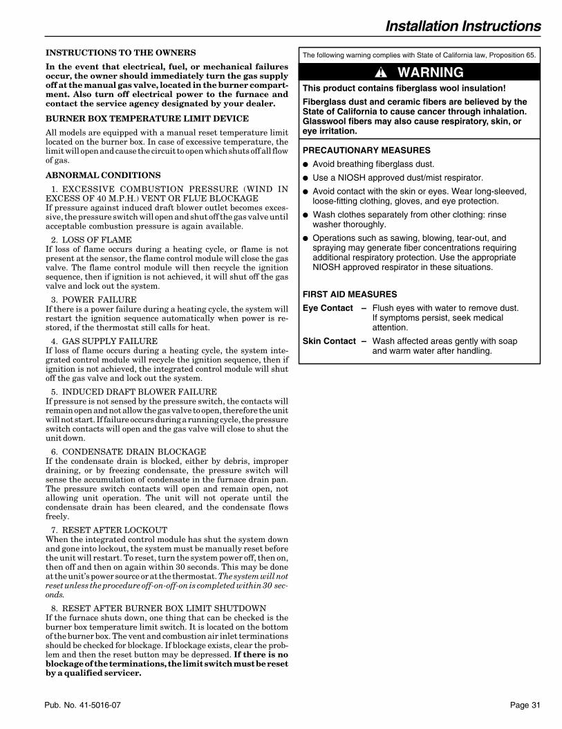
Installation Instructions
Page 31Pub. No. 41-5016-07
INSTRUCTIONS TO THE OWNERS
In the event that electrical, fuel, or mechanical failuresoccur, the owner should immediately turn the gas supplyoff at the manual gas valve, located in the burner compart-ment. Also turn off electrical power to the furnace andcontact the service agency designated by your dealer.
BURNER BOX TEMPERATURE LIMIT DEVICE
All models are equipped with a manual reset temperature limitlocated on the burner box. In case of excessive temperature, thelimit will open and cause the circuit to open which shuts off all flowof gas.
ABNORMAL CONDITIONS
1. EXCESSIVE COMBUSTION PRESSURE (WIND INEXCESS OF 40 M.P.H.) VENT OR FLUE BLOCKAGEIf pressure against induced draft blower outlet becomes exces-sive, the pressure switch will open and shut off the gas valve untilacceptable combustion pressure is again available.
2. LOSS OF FLAMEIf loss of flame occurs during a heating cycle, or flame is notpresent at the sensor, the flame control module will close the gasvalve. The flame control module will then recycle the ignitionsequence, then if ignition is not achieved, it will shut off the gasvalve and lock out the system.
3. POWER FAILUREIf there is a power failure during a heating cycle, the system willrestart the ignition sequence automatically when power is re-stored, if the thermostat still calls for heat.
4. GAS SUPPLY FAILUREIf loss of flame occurs during a heating cycle, the system inte-grated control module will recycle the ignition sequence, then ifignition is not achieved, the integrated control module will shutoff the gas valve and lock out the system.
5. INDUCED DRAFT BLOWER FAILUREIf pressure is not sensed by the pressure switch, the contacts willremain open and not allow the gas valve to open, therefore the unitwill not start. If failure occurs during a running cycle, the pressureswitch contacts will open and the gas valve will close to shut theunit down.
6. CONDENSATE DRAIN BLOCKAGEIf the condensate drain is blocked, either by debris, improperdraining, or by freezing condensate, the pressure switch willsense the accumulation of condensate in the furnace drain pan.The pressure switch contacts will open and remain open, notallowing unit operation. The unit will not operate until thecondensate drain has been cleared, and the condensate flowsfreely.
7. RESET AFTER LOCKOUTWhen the integrated control module has shut the system downand gone into lockout, the system must be manually reset beforethe unit will restart. To reset, turn the system power off, then on,then off and then on again within 30 seconds. This may be doneat the unit’s power source or at the thermostat. The system will notreset unless the procedure off-on-off-on is completed within 30 sec-onds.
8. RESET AFTER BURNER BOX LIMIT SHUTDOWNIf the furnace shuts down, one thing that can be checked is theburner box temperature limit switch. It is located on the bottomof the burner box. The vent and combustion air inlet terminationsshould be checked for blockage. If blockage exists, clear the prob-lem and then the reset button may be depressed. If there is noblockage of the terminations, the limit switch must be resetby a qualified servicer.
▲ WARNING!
The following warning complies with State of California law, Proposition 65.
This product contains fiberglass wool insulation!
Fiberglass dust and ceramic fibers are believed by the State of California to cause cancer through inhalation. Glasswool fibers may also cause respiratory, skin, or eye irritation.
PRECAUTIONARY MEASURES
● Avoid breathing fiberglass dust.
● Use a NIOSH approved dust/mist respirator.
● Avoid contact with the skin or eyes. Wear long-sleeved, loose-fitting clothing, gloves, and eye protection.
● Wash clothes separately from other clothing: rinse washer thoroughly.
● Operations such as sawing, blowing, tear-out, and spraying may generate fiber concentrations requiring additional respiratory protection. Use the appropriate NIOSH approved respirator in these situations.
FIRST AID MEASURES
Eye Contact – Flush eyes with water to remove dust. If symptoms persist, seek medical attention.
Skin Contact – Wash affected areas gently with soap and warm water after handling.

Owner’s Information
Pub. No. 41-5016-07Page 32
User’s Information GuideUpflow/Horizontal and Downflow/ Horizontal,Single Stage Gas-Fired Condensing Furnaces
Contents:Warnings & Cautions .............................................. 32General Information ............................................... 32To Start The Furnace ......................................... 33-34Proper Maintenance ........................................... 35-36The Problem Solver ................................................. 37Regular Dealer Maintenance ................................. 38Warranties ............................................................ 50-51
GENERAL INFORMATION
Understand the signal words WARNING and CAUTION. Thesewords are safety alert words. WARNING indicates hazards whichcould result in personal injury or death. CAUTION is used toindicate unsafe practices which could result in minor injury orproperty damage.
▲ WARNING!If the information in this manual is not followed exactly, a fire or explosion may result causing property damage, personal injury or loss of life.
— Do not store or use gasoline or other flammable vapors and liquids in the vicinity of this or any other appliance.
— WHAT TO DO IF YOU SMELL GAS
• Do not try to light any appliance.
• Do not touch any electrical switch; do not use any phone in your building.
• Immediately call your gas supplier from a neighbor’s phone. Follow the gas supplier’s instructions.
• If you cannot reach your gas supplier, call the fire department.
— DO NOT RELY ON SMELL ALONE TO DETECT LEAKS. DUE TO VARIOUS FACTORS, YOU MAY NOT BE ABLE TO SMELL FUEL GASES.
• U.L. recognized fuel gas and CO detectors are recommended in all applications, and their installation should be in accordance with the manufacturer's recommendations and/or local laws, rules, regulations, or customs.
— Installation and service must be performed by a qualified installer, service agency or the gas supplier.
OWNER’S INFORMATION
IMPORTANT FACTS
The flow of combustion and ventilating air must not be obstructedfrom reaching the furnace. Air openings provided in the casing ofthe furnace must be kept free of obstructions which would restrictairflow, thereby affecting efficiency and safe operation of yourfurnace.
Also, air openings provided to the area in which the furnace isinstalled and the space around the furnace shall not be blocked orobstructed. Keep this in mind should you choose to remodel thearea which contains your furnace. If additional insulation isadded after the furnace is installed, the area around the furnacemust be inspected to ensure it is free and clear of insulation. If thisfurnace is installed in an attic or other insulated space it must bekept free and clear of all insulating materials as some insulatingmaterials are combustible.
Furnaces must have air for proper performance. There must be afree flow of fresh air sufficient for efficient combustion and safeventilation of your furnace.
The combustion air for your furnace must be fresh uncontami-nated air. Paints, varnishes, laundry bleaches, detergents, manyhousehold cleaners, water softening salts, adhesives, and all suchproducts release fumes containing compounds which could lead toearly heat exchanger and vent system deterioration. Do not storethese type of products near your furnace.
Never store gasoline, combustible materials, or other flam-mable liquids or vapors near your furnace.
Carbon monoxide, fire or smoke can cause serious bodily injury,death, and/or property damage.
A variety of potential sources of carbon monoxide can be found ina building or dwelling such as gas-fired clothes dryers, gascooking stoves, water heaters, furnaces and fireplaces. The U.S.Consumer Product Safety Commission recommends that users ofgas-burning appliances install carbon monoxide detectors as wellas fire and smoke detectors per the manufacturer’s installationinstructions to help alert dwelling occupants of the presence offire, smoke or unsafe levels of carbon monoxide. These devicesshould be listed by Underwriters Laboratories, Inc. Standards forSingle and Multiple Station Carbon Monoxide Alarms, UL 2034or CSA International Standard, Residential Carbon MonoxideAlarming Devices, CSA 6.19
▲ WARNING!DO NOT USE THIS UNIT IF ANY PART HAS BEEN UNDERWATER. IMMEDIATELY CALL A QUALIFIED SERVICE TECHNI-CIAN TO INSPECT THE FURNACE AND REPLACE ANY PARTOF THE CONTROL SYSTEM AND ANY GAS CONTROL WHICHHAS BEEN UNDER WATER.
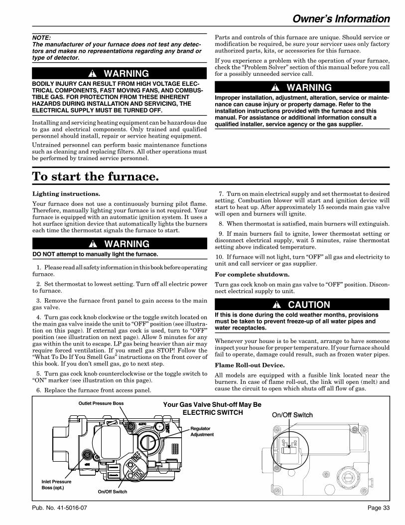
Owner’s Information
Page 33Pub. No. 41-5016-07
Lighting instructions.
Your furnace does not use a continuously burning pilot flame.Therefore, manually lighting your furnace is not required. Yourfurnace is equipped with an automatic ignition system. It uses ahot surface ignition device that automatically lights the burnerseach time the thermostat signals the furnace to start.
▲ WARNING!DO NOT attempt to manually light the furnace.
1. Please read all safety information in this book before operatingfurnace.
2. Set thermostat to lowest setting. Turn off all electric powerto furnace.
3. Remove the furnace front panel to gain access to the maingas valve.
4. Turn gas cock knob clockwise or the toggle switch located onthe main gas valve inside the unit to “OFF” position (see illustra-tion on this page). If external gas cock is used, turn to “OFF”position (see illustration on next page). Allow 5 minutes for anygas within the unit to escape. LP gas being heavier than air mayrequire forced ventilation. If you smell gas STOP! Follow the“What To Do If You Smell Gas” instructions on the front cover ofthis book. If you don’t smell gas, go to next step.
5. Turn gas cock knob counterclockwise or the toggle switch to“ON” marker (see illustration on this page).
6. Replace the furnace front access panel.
To start the furnace.
NOTE:The manufacturer of your furnace does not test any detec-tors and makes no representations regarding any brand ortype of detector.
▲ WARNING!BODILY INJURY CAN RESULT FROM HIGH VOLTAGE ELEC-TRICAL COMPONENTS, FAST MOVING FANS, AND COMBUS-TIBLE GAS. FOR PROTECTION FROM THESE INHERENTHAZARDS DURING INSTALLATION AND SERVICING, THEELECTRICAL SUPPLY MUST BE TURNED OFF.
Installing and servicing heating equipment can be hazardous dueto gas and electrical components. Only trained and qualifiedpersonnel should install, repair or service heating equipment.Untrained personnel can perform basic maintenance functionssuch as cleaning and replacing filters. All other operations mustbe performed by trained service personnel.
7. Turn on main electrical supply and set thermostat to desiredsetting. Combustion blower will start and ignition device willstart to heat up. After approximately 15 seconds main gas valvewill open and burners will ignite.
8. When thermostat is satisfied, main burners will extinguish.
9. If main burners fail to ignite, lower thermostat setting ordisconnect electrical supply, wait 5 minutes, raise thermostatsetting above indicated temperature.
10. If furnace will not light, turn “OFF” all gas and electricity tounit and call servicer or gas supplier.
For complete shutdown.
Turn gas cock knob on main gas valve to “OFF” position. Discon-nect electrical supply to unit.
▲ CAUTION!If this is done during the cold weather months, provisionsmust be taken to prevent freeze-up of all water pipes andwater receptacles.
Whenever your house is to be vacant, arrange to have someoneinspect your house for proper temperature. If your furnace shouldfail to operate, damage could result, such as frozen water pipes.
Flame Roll-out Device.
All models are equipped with a fusible link located near theburners. In case of flame roll-out, the link will open (melt) andcause the circuit to open which shuts off all flow of gas.
Parts and controls of this furnace are unique. Should service ormodification be required, be sure your servicer uses only factoryauthorized parts, kits, or accessories for this furnace.
If you experience a problem with the operation of your furnace,check the “Problem Solver” section of this manual before you callfor a possibly unneeded service call.
▲ WARNING!Improper installation, adjustment, alteration, service or mainte-nance can cause injury or property damage. Refer to theinstallation instructions provided with the furnace and thismanual. For assistance or additional information consult aqualified installer, service agency or the gas supplier.
On/Offff SwiSwitchch
Your Gas Valve Shut-off May Be ELECTRIC SWITCH
Outlet Pressure Boss
RegulatorAdjustment
Inlet PressureBoss (opt.)
On/Off Switch
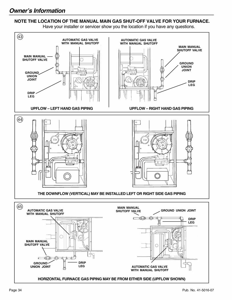
Owner’s Information
Pub. No. 41-5016-07Page 34
NOTE THE LOCATION OF THE MANUAL MAIN GAS SHUT-OFF VALVE FOR YOUR FURNACE.Have your installer or servicer show you the location if you have any questions.
HORIZONTAL FURNACE GAS PIPING MAY BE FROM EITHER SIDE (UPFLOW SHOWN)
AUTOMATIC GAS VALVEWITH MANUAL SHUTOFF
MAIN MANUALSHUTOFF VALVE
GROUNDUNION JOINT
DRIPLEG
MAIN MANUALSHUTOFF VALVE GROUND UNION JOINT
DRIPLEG
AUTOMATIC GAS VALVEWITH MANUAL SHUTOFF
%
THE DOWNFLOW (VERTICAL) MAY BE INSTALLED LEFT OR RIGHT SIDE GAS PIPING
$
UPFLOW – LEFT HAND GAS PIPING UPFLOW – RIGHT HAND GAS PIPING
# AUTOMATIC GAS VALVEWITH MANUAL SHUTOFF
MAIN MANUALSHUTOFF VALVE
GROUNDUNIONJOINT
DRIPLEG
AUTOMATIC GAS VALVEWITH MANUAL SHUTOFF
MAIN MANUALSHUTOFF VALVE
GROUNDUNIONJOINT
DRIPLEG

Owner’s Information
Page 35Pub. No. 41-5016-07
Proper maintenance reduces energy use.A clean filter saves money.
When the furnace circulates and filters the air in your home, dustand dirt particles build up on the filter. Excessive accumulationcan block the airflow, forcing the unit to work harder to maintaindesired temperatures.
And the harder your unit has to work, the more energy it uses. Soyou pay more any time your system is running with a dirty filter.
▲ CAUTION!Never operate your unit for either heating or cooling with filtersremoved.
Help ensure top efficiency by cleaning the filter once a month. Cleanit twice a month during seasons when the unit runs more often.
You can clean the filter with a vacuum, OR you can wash it witha household detergent.
Both methods are quick and easy, and guaranteed to improve theperformance of your system.
For vertical UPFLOW ONLY, a left or right return air inlet asabove (left side shown) requires trimming of the factory suppliedfilter to 17" x 25" x 1" for both the 21" and 24-1/2" wide furnaces.
Air filters may also be located outside of the furnace using a SIDEFILTER FRAME.
Replacing your filter.
When replacing your furnace filters, always use a high velocitytype which are the same size as originally supplied. Filters areavailable from your dealer.
Where disposable filters are used, they must be a high velocitytype which are the same size as originally supplied.
How to remove your filter.
▲ WARNING!Disconnect power to unit before removing blower door.
Upflow furnaces use a high velocity type air filter which may belocated within the furnace blower compartment in either aBOTTOM or SIDE (left or right) return air inlet. The furnace maybe secured with filter retaining brackets (as shown) or a filterretainer wire.
To replace filters, remove blower access door, push back to flex thefilter and clear the filter retaining bracket at the front of the unit.After cleaning, replace the filter in the same manner making surethat the filter wire is secured in place in both front and back filterretaining brackets. Replace blower access door.
A bottom return air inlet as shown features a 17" x 25" x 1" filterin the 17-1/2" wide furnace cabinets; a 20" x 25" x 1" filter in the21" wide models; and a 24" x 25" x 1" filter in the 24-1/2" widecabinet.
Your filter may or may not be framed.
UPFLOW BOTTOM RETURN
Airflow
UPFLOW SIDE RETURN
Airflow
UPFLOW ONLY
Airf
low

Owner’s Information
Pub. No. 41-5016-07Page 36
Downflow/Horizontal furnaces are factory supplied with 2 stan-dard size permanent type air filters which may be located remoteto the furnace or in the return air duct. Check with your dealer forthe location of your filters.
A downflow/horizontal furnace return air filter application, asshown, features two 14" x 20" x 1" filter in the 17-1/2" wide furnacecabinets; or two 16" x 20" x 1" filter in the 21" and 24-1/2" widefurnace cabinets.
DOWNFLOW (Vertical) FILTER TABLE
REQUIRED FILTERS - SIDE **
CABINET WIDTH FILTER QUANTITY & SIZE
17-1/2" 1 - 17" X 25" X 1"
21" 1 - 20" X 25" X 1"
24-1/2" 1 - 24" X 25" X 1"
** ON UPFLOW 5 TON AIRFLOW MODELS, IF THEAIRFLOW REQUIREMENT EXCEEDS 1800 CFM, THESEMODELS WILL REQUIRE FILTERS ON BOTH SIDES OR1 SIDE AND THE BOTTOM, OR JUST THE BOTTOM
REQUIRED FILTERS - DOWNFLOW
CABINET WIDTH FILTER QUANTITY & SIZE
17-1/2" 2 - 16" X 20" X 1"
21" 2 - 16" X 20" X 1"
24-1/2" 2 - 16" X 20" X 1"
DOWNFLOW FILTER
Airflow
DOWNFLOW/HORIZONTAL FILTER
Airflow
TYPICAL RETURN AIR FILTER INSTALLATION INUPFLOW MODEL IN HORIZONTAL POSITION
Airflow
UPFLOW (Vertical) FILTER TABLES
REQUIRED FILTERS - BOTTOM
CABINET WIDTH FILTER QUANTITY & SIZE
17-1/2" 1 - 17" X 25" X 1"
21" 1 - 20" X 25" X 1"
24-1/2" 1 - 24" X 25" X 1"

Owner’s Information
Page 37Pub. No. 41-5016-07
The problem solver.A furnace is not a household appliance. It is complex and requiresprofessional maintenance and repair.
That’s why attempts at “do-it-yourself” repairs on an in-warrantyunit may void the remainder of your warranty.
Other than performing the simple maintenance recommended inthis manual, you should not attempt to make any adjustments toyour furnace. Your dealer will be able to take care of any questionsor problems you may have. A periodic inspection of your furnaceshould be made by a qualified service agency at the start of eachheating season.
Keep your furnace looking like new for years.
Clean the enamel finish of your furnace with ordinary soap andwater. For stubborn grease spots, use a household detergent.Lacquer thinner or other synthetic solvents may damage the finish.
▲ WARNING!
The following warning complies with State of California law, Proposition 65.
THIS PRODUCT CONTAINS FIBERGLASS WOOL INSULATION!
Fiberglass dust and ceramic fibers are believed by the State of California to cause cancer through inhalation. Glasswool fibers may also cause respiratory, skin, or eye irritation.
PRECAUTIONARY MEASURES
● Avoid breathing fiberglass dust.
● Use a NIOSH approved dust/mist respirator.
● Avoid contact with the skin or eyes. Wear long-sleeved, loose-fitting clothing, gloves, and eye protection.
● Wash clothes separately from other clothing: rinse washer thoroughly.
● Operations such as sawing, blowing, tear-out, and spraying may generate fiber concentrations requiring additional respiratory protection. Use the appropriate NIOSH approved respirator in these situations.
FIRST AID MEASURES
Eye Contact – Flush eyes with water to remove dust. If symptoms persist, seek medical attention.
Skin Contact – Wash affected areas gently with soap and warm water after handling.
▲ WARNING!CARBON MONOXIDE POISONING HAZARD
Failure to follow the installation and operation instructions for the ventingsystem’s operation could result in carbon monoxide poisoning or death.
Save time and money. Before calling for service, check the following:Problem Possible Trouble Possible Remedy
No Heating - Blower 1. Thermostat set incorrectly. 1. Adjust thermostat. See operatingDoes not operate instructions.
2. Blown fuse or tripped circuit breaker. 2. Replace or reset protective deviceor call for servicer.
3. Defective component. 3. Most controls are automatic and willrecycle. If your unit still does notoperate call for servicer.
4. Burner does not ignite. 4. Call servicer.5. Main gas line turned off. 5. Have gas company check.6. Blower door removed or ajar. 6. Close door securely to restore power
to blower and gas valve.7. Lockout 7. Turn power on-off-on-off twice
in 30 seconds.
Insufficient Heating - 1. Dirty air filters. 1. Clean or replace filters.Blower operates 2. Blocked supply or 2. Make sure registers are open andcontinuously return registers. No obstacles blocking off the air.
No Heat - Vent motor Restricted or plugged furnace 1. Remove drain clamps to condensateis running condensate drain. trap and drain pan outlet.
2. Flush or clean drain blockage.3. Reinstall clamps.
Unusual Noise Call your servicer

Owner’s Information
Pub. No. 41-5016-07Page 38
Never stop the cooling system by shutting off the mainpower.
If the main power to your air conditioner is ever disconnected formore than three hours, turn off the thermostat. Then wait for atleast three more hours after the power has been restored beforeturning the thermostat back on. Failure to follow this procedurecould result in damage to your air conditioning system.
1. GENERAL INSPECTION — Examine the furnace installa-tion for the following items:
a. All flue product carrying areas external to the furnace (i.e.chimney, vent connector) are clear and free of obstruction.
b. The vent connector is in place, slopes upward and isphysically sound without holes or excessive corrosion.
c. The return air duct connection(s) is physically sound, issealed to the furnace and terminates outside the spacecontaining the furnace.
d. The physical support of the furnace should be soundwithout sagging, cracks, gaps, etc., around the base so asto provide a seal between the support and the base.
e. There are no obvious signs of deterioration of the furnace.
Regular dealer maintenance.
2. BLOWERS — The blower size and speed determine the airvolume delivered by the furnace. The blower motor bearings arefactory lubricated and under normal operating conditions usuallydo not require servicing. Annual cleaning of the blower wheel andhousing is recommended for maximum air output, and this mustbe performed only by a qualified servicer or service agency.
▲ WARNING!Unit is equipped with a blower door switch which cuts powerto blower and gas valve causing shutdown when door isremoved. Unit must not be altered to allow operation with theblower door removed. Operation with doors removed or ajarcan permit the escape of dangerous fumes. All panels must besecurely closed at all times for safe operation of the furnace.
3. IGNITER — This unit has a special hot surface directignition device that automatically lights the burners. Please notethat it is very fragile and should be handled with care.
▲ CAUTION!DO NOT touch igniter. It is extremely hot.
4. BURNER — Gas burners do not normally require scheduledservicing, however, accumulation of foreign material may causea yellowing flame or delayed ignition. Either condition indicatesthat a service call is required. For best operation, burners must becleaned annually using brushes and vacuum cleaner.
Turn off gas and electric power supply. To clean burners, removetop burner bracket and lift burner from orifice.
NOTE:Be careful not to break igniter when removing burners.
NOTE:On LP (propane) units, due to variations in BTU content andaltitude, servicing may be required at shorter intervals.
5. HEAT EXCHANGER/FLUE PIPE — These items must beinspected for signs of corrosion, and/or deterioration at the begin-ning of each heating season by a qualified service technician andcleaned annually for best operation.
6. CIRCUIT PROTECTION — If blower or gas valve fail tooperate, the cause could be the circuit breaker or a loose or blownfuse. Replace fuse or reset circuit breaker.
7. OPERATION — Your warm air furnace should not be oper-ated in a corrosive atmosphere. Paint solvents, cleaning chemi-cals, spray propellants, and bleaches should not be used in thevicinity of the furnace during normal operation.
8. COOLING COIL CONDENSATE DRAIN — If you have acooling coil installed with your furnace, condensate drains shouldbe checked and cleaned periodically to assure that condensate candrain freely from coil to drain. If condensate cannot drain freelywater damage could occur.
9. AIR CIRCULATION — To ensure increased comfort, theblower on this unit may be operated continuously for both heatingand cooling. This will result in constantly filtered air and aid inmaintaining more even temperatures by avoiding temperaturestratification throughout the conditioned area. To accomplishconstant air circulation, set your thermostat fan switch to “ON”.
▲ WARNING!Should overheating occur, or the gas supply fail to shut off,shut off the manual gas valve to the furnace before shutting offthe electrical supply.
In the event that electrical, fuel or mechanical failures occur, theowner should immediately turn off the gas supply at the manualgas valve located in the burner compartment and electrical powerto the furnace and contact servicer.
Clean burners with brush and/or vacuum cleaner. Reassembleparts by reversal of the above procedure.
NOTE:On LP (propane) units, some light yellow tipping of the outermantle is normal. Inner mantle should be bright blue.
Natural gas units should not have any yellow tipped flames.This condition indicates that a service call is required. For bestoperation, burners must be cleaned annually using brushesand vacuum cleaner.
The following warning complies with State of California law, Proposition 65.
Hazardous Gases!
Exposure to fuel substances or by-products of incomplete fuel combustion is believed by the state of California to cause cancer, birth defects, or other reproductive harm.
▲ WARNING!
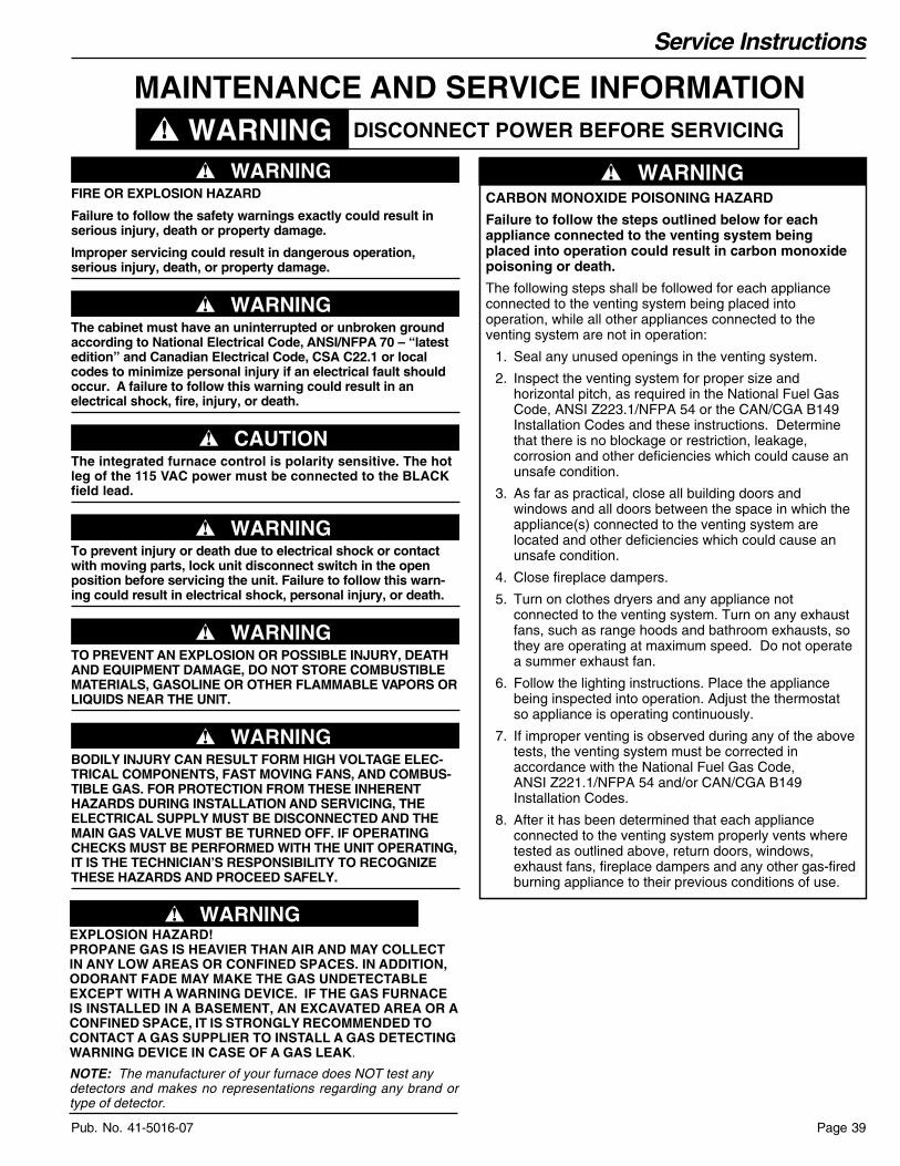
Service Instructions
Page 39Pub. No. 41-5016-07
MAINTENANCE AND SERVICE INFORMATIONDISCONNECT POWER BEFORE SERVICINGWARNING
▲ WARNING!FIRE OR EXPLOSION HAZARD
Failure to follow the safety warnings exactly could result inserious injury, death or property damage.
Improper servicing could result in dangerous operation,serious injury, death, or property damage.
▲ WARNING!The cabinet must have an uninterrupted or unbroken groundaccording to National Electrical Code, ANSI/NFPA 70 – “latestedition” and Canadian Electrical Code, CSA C22.1 or localcodes to minimize personal injury if an electrical fault shouldoccur. A failure to follow this warning could result in anelectrical shock, fire, injury, or death.
▲ CAUTION!The integrated furnace control is polarity sensitive. The hotleg of the 115 VAC power must be connected to the BLACKfield lead.
▲ WARNING!To prevent injury or death due to electrical shock or contactwith moving parts, lock unit disconnect switch in the openposition before servicing the unit. Failure to follow this warn-ing could result in electrical shock, personal injury, or death.
▲ WARNING!TO PREVENT AN EXPLOSION OR POSSIBLE INJURY, DEATHAND EQUIPMENT DAMAGE, DO NOT STORE COMBUSTIBLEMATERIALS, GASOLINE OR OTHER FLAMMABLE VAPORS ORLIQUIDS NEAR THE UNIT.
▲ WARNING!BODILY INJURY CAN RESULT FORM HIGH VOLTAGE ELEC-TRICAL COMPONENTS, FAST MOVING FANS, AND COMBUS-TIBLE GAS. FOR PROTECTION FROM THESE INHERENTHAZARDS DURING INSTALLATION AND SERVICING, THEELECTRICAL SUPPLY MUST BE DISCONNECTED AND THEMAIN GAS VALVE MUST BE TURNED OFF. IF OPERATINGCHECKS MUST BE PERFORMED WITH THE UNIT OPERATING,IT IS THE TECHNICIAN’S RESPONSIBILITY TO RECOGNIZETHESE HAZARDS AND PROCEED SAFELY.
CARBON MONOXIDE POISONING HAZARD
Failure to follow the steps outlined below for each appliance connected to the venting system being placed into operation could result in carbon monoxide poisoning or death.
The following steps shall be followed for each appliance connected to the venting system being placed into operation, while all other appliances connected to the venting system are not in operation:
1. Seal any unused openings in the venting system.
2. Inspect the venting system for proper size and horizontal pitch, as required in the National Fuel Gas Code, ANSI Z223.1/NFPA 54 or the CAN/CGA B149 Installation Codes and these instructions. Determine that there is no blockage or restriction, leakage, corrosion and other deficiencies which could cause an unsafe condition.
3. As far as practical, close all building doors and windows and all doors between the space in which the appliance(s) connected to the venting system are located and other deficiencies which could cause an unsafe condition.
4. Close fireplace dampers.
5. Turn on clothes dryers and any appliance not connected to the venting system. Turn on any exhaust fans, such as range hoods and bathroom exhausts, so they are operating at maximum speed. Do not operate a summer exhaust fan.
6. Follow the lighting instructions. Place the appliance being inspected into operation. Adjust the thermostat so appliance is operating continuously.
7. If improper venting is observed during any of the above tests, the venting system must be corrected in accordance with the National Fuel Gas Code, ANSI Z221.1/NFPA 54 and/or CAN/CGA B149 Installation Codes.
8. After it has been determined that each appliance connected to the venting system properly vents where tested as outlined above, return doors, windows, exhaust fans, fireplace dampers and any other gas-fired burning appliance to their previous conditions of use.
▲ WARNING!
SERVICE INSTRUCTIONS
▲ WARNING!EXPLOSION HAZARD!PROPANE GAS IS HEAVIER THAN AIR AND MAY COLLECTIN ANY LOW AREAS OR CONFINED SPACES. IN ADDITION,ODORANT FADE MAY MAKE THE GAS UNDETECTABLEEXCEPT WITH A WARNING DEVICE. IF THE GAS FURNACEIS INSTALLED IN A BASEMENT, AN EXCAVATED AREA OR ACONFINED SPACE, IT IS STRONGLY RECOMMENDED TOCONTACT A GAS SUPPLIER TO INSTALL A GAS DETECTINGWARNING DEVICE IN CASE OF A GAS LEAK.
NOTE: The manufacturer of your furnace does NOT test anydetectors and makes no representations regarding any brand ortype of detector.

Service Instructions
Pub. No. 41-5016-07Page 40
MODELTYPERATINGS 2Input BTUH 3Capacity BTUH (ICS) 3Temp. rise (Min.-Max.) °F.AFUEBLOWER DRIVEDiameter - Width (In.)No. UsedSpeeds (No.)CFM vs. in. w.g.Motor HPR.P.M.Volts / Ph / HzCOMBUSTION FAN - TypeDrive - No. SpeedsMotor HP - RPMVolts / Ph / HzFLAFILTER — Furnished?Type RecommendedHi Vel. (No.-Size-Thk.)VENT — Size (in.)HEAT EXCHANGERType -Fired
-UnfiredGauge (Fired)ORIFICES — MainNat. Gas. Qty. — Drill SizeL.P. Gas Qty. — Drill SizeGAS VALVEPILOT SAFETY DEVICETypeBURNERS — TypeNumberPOWER CONN. — V / Ph / Hz 4Ampacity (In Amps)Max. Overcurrent Protection (Amps)PIPE CONN. SIZE (IN.)DIMENSIONSCrated (In.)WEIGHTShipping (Lbs.) / Net (Lbs.)
CUX1B040A9241AUpflow
40,00037,00030 - 60
90.0DIRECT
9 x 714
See Fan Performance Table1/5
1075115/1/60
CentrifugalDirect - 1
1/55 - 3000115/1/60
1.0No
High Velocity1 - 17x25 - 1in.
2 Round
Aluminized Steel - Type I
20
2 — 452 — 56
Redundant - Single Stage
Hot Surface IgnitionMultiport Inshot
2115/1/60
4.7151/2
H x W x D41-3/4 x 19-1/2 x 30-1/2
139 / 129
CUX1B060A9361AUpflow
60,00056,00030 - 60
90.0DIRECT10 x 7
14
See Fan Performance Table1/3
1075115/1/60
CentrifugalDirect - 1
1/55 - 3000115/1/60
1.0No
High Velocity1 - 17x25 - 1in.
2 Round
Aluminized Steel - Type I
20
3 — 453 — 56
Redundant - Single Stage
Hot Surface IgnitionMultiport Inshot
3115/1/60
8.3151/2
H x W x D41-3/4 x 19-1/2 x 30-1/2
150 / 140
CUX1B080A9421AUpflow
80,00074,00035 - 65
90.0DIRECT10 x 8
14
See Fan Performance Table1/3
1075115/1/60
CentrifugalDirect - 1
1/25 - 3200115/1/60
1.35No
High Velocity1 - 17x25 - 1in.
2 Round
Aluminized Steel - Type I
20
4 — 454 — 56
Redundant - Single Stage
Hot Surface IgnitionMultiport Inshot
4115/1/60
9.4151/2
H x W x D41-3/4 x 19-1/2 x 30-1/2
158 / 148
CUX1D100A9601AUpflow
100,00093,00035 - 65
90.0DIRECT11 x 10
14
See Fan Performance Table3/4
1100115/1/60
CentrifugalDirect - 1
1/20 - 3450115/1/60
0.71No
High Velocity1 - 24x25 - 1in.
2 Round
Aluminized Steel - Type I
20
5 — 455 — 56
Redundant - Single Stage
Hot Surface IgnitionMultiport Inshot
5115/1/60
12.9151/2
H x W x D41-3/4 x 26-1/2 x 30-1/2
197 / 185
CUX1D120A9601AUpflow
120,000113,00040 - 70
90.0DIRECT11 x 10
14
See Fan Performance Table3/4
1100115/1/60
CentrifugalDirect - 1
1/20 - 3450115/1/60
0.71No
High Velocity1 - 24x25 - 1in.
3 Round
Aluminized Steel - Type I
20
6 — 456 — 56
Redundant - Single Stage
Hot Surface IgnitionMultiport Inshot
6115/1/60
12.9151/2
H x W x D41-3/4 x 26-1/2 x 30-1/2
205 / 193
CUX1C100A9481AUpflow
100,00092,00035 - 65
90.0DIRECT10 x 10
14
See Fan Performance Table1/2
1075115/1/60
CentrifugalDirect - 1
1/20 - 3450115/1/60
0.71No
High Velocity1 - 20x25 - 1in.
2 Round
Aluminized Steel - Type I
20
5 — 455 — 56
Redundant - Single Stage
Hot Surface IgnitionMultiport Inshot
5115/1/60
12.5151/2
H x W x D41-3/4 x 23 x 30-1/2
171 / 160
PRODUCT SPECIFICATIONS 1
1 Central Furnace heating designs are certified by AGA & CSA.2 For U.S. applications, above input ratings (BTUH) are up to 2,000 ft., derate 4% per 1,000 ft. for elevations above 2,000 ft. above sea level.
For Canadian applications, above input ratings (BTUH) are up to 4,500 ft., derate 4% per 1,000 ft. for elevations above 4,500 ft. above sea level.3 Based on U.S. government standard tests.4 The above wiring specifications are in accordance with National Electrical Code; however, installations must comply with local codes.
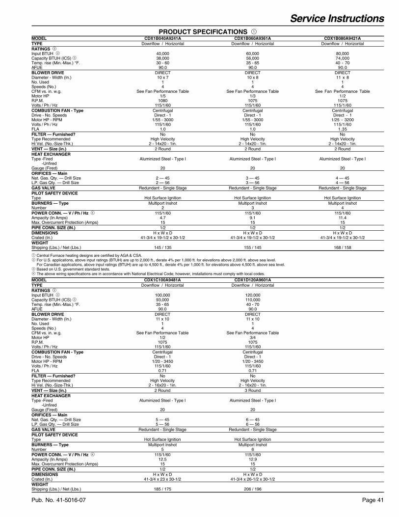
Service Instructions
Page 41Pub. No. 41-5016-07
MODELTYPERATINGS 2Input BTUH 3Capacity BTUH (ICS) 3Temp. rise (Min.-Max.) °F.AFUEBLOWER DRIVEDiameter - Width (In.)No. UsedSpeeds (No.)CFM vs. in. w.g.Motor HPR.P.M.Volts / Ph / HzCOMBUSTION FAN - TypeDrive - No. SpeedsMotor HP - RPMVolts / Ph / HzFLAFILTER — Furnished?Type RecommendedHi Vel. (No.-Size-Thk.)VENT — Size (in.)HEAT EXCHANGERType -Fired
-UnfiredGauge (Fired)ORIFICES — MainNat. Gas. Qty. — Drill SizeL.P. Gas Qty. — Drill SizeGAS VALVEPILOT SAFETY DEVICETypeBURNERS — TypeNumberPOWER CONN. — V / Ph / Hz 4Ampacity (In Amps)Max. Overcurrent Protection (Amps)PIPE CONN. SIZE (IN.)DIMENSIONSCrated (In.)WEIGHTShipping (Lbs.) / Net (Lbs.)
CDX1B040A9241ADownflow / Horizontal
40,00038,00030 - 60
90.0DIRECT10 x 7
14
See Fan Performance Table1/5
1080115/1/60
CentrifugalDirect - 1
1/55 - 3000115/1/60
1.0No
High Velocity2 - 14x20 - 1in.
2 Round
Aluminized Steel - Type I
20
2 — 452 — 56
Redundant - Single Stage
Hot Surface IgnitionMultiport Inshot
2115/1/60
4.7151/2
H x W x D41-3/4 x 19-1/2 x 30-1/2
145 / 135
CDX1B060A9361ADownflow / Horizontal
60,00056,00035 - 65
90.0DIRECT10 x 8
14
See Fan Performance Table1/3
1075115/1/60
CentrifugalDirect - 1
1/55 - 3000115/1/60
1.0No
High Velocity2 - 14x20 - 1in.
2 Round
Aluminized Steel - Type I
20
3 — 453 — 56
Redundant - Single Stage
Hot Surface IgnitionMultiport Inshot
3115/1/60
9.1151/2
H x W x D41-3/4 x 19-1/2 x 30-1/2
155 / 145
CDX1B080A9421ADownflow / Horizontal
80,00074,00040 - 70
90.0DIRECT11 x 8
14
See Fan Performance Table1/2
1075115/1/60
CentrifugalDirect - 1
1/25 - 3200115/1/60
1.35No
High Velocity2 - 14x20 - 1in.
2 Round
Aluminized Steel - Type I
20
4 — 454 — 56
Redundant - Single Stage
Hot Surface IgnitionMultiport Inshot
4115/1/60
11.4151/2
H x W x D41-3/4 x 19-1/2 x 30-1/2
168 / 158
CDX1D120A9601ADownflow / Horizontal
120,000110,00040 - 70
90.0DIRECT11 x 10
14
See Fan Performance Table3/4
1075115/1/60
CentrifugalDirect - 1
1/20 - 3450115/1/60
0.71No
High Velocity2 - 16x20 - 1in.
3 Round
Aluminized Steel - Type I
20
6 — 456 — 56
Redundant - Single Stage
Hot Surface IgnitionMultiport Inshot
6115/1/60
12.9151/2
H x W x D41-3/4 x 26-1/2 x 30-1/2
206 / 196
CDX1C100A9481ADownflow / Horizontal
100,00093,00035 - 65
90.0DIRECT11 x 10
14
See Fan Performance Table1/2
1075115/1/60
CentrifugalDirect - 1
1/20 - 3450115/1/60
0.71No
High Velocity2 - 16x20 - 1in.
2 Round
Aluminized Steel - Type I
20
5 — 455 — 56
Redundant - Single Stage
Hot Surface IgnitionMultiport Inshot
5115/1/60
12.5151/2
H x W x D41-3/4 x 23 x 30-1/2
185 / 175
PRODUCT SPECIFICATIONS 1
1 Central Furnace heating designs are certified by AGA & CSA.2 For U.S. applications, above input ratings (BTUH) are up to 2,000 ft., derate 4% per 1,000 ft. for elevations above 2,000 ft. above sea level.
For Canadian applications, above input ratings (BTUH) are up to 4,500 ft., derate 4% per 1,000 ft. for elevations above 4,500 ft. above sea level.3 Based on U.S. government standard tests.4 The above wiring specifications are in accordance with National Electrical Code; however, installations must comply with local codes.
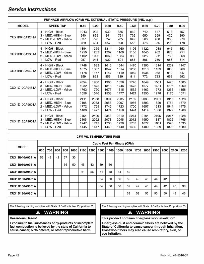
Service Instructions
Pub. No. 41-5016-07Page 42
FURNACE AIRFLOW (CFM) VS. EXTERNAL STATIC PRESSURE (INS. w.g.)
MODEL SPEED TAP 0.10 0.20 0.30 0.40 0.50 0.60 0.70 0.80 0.90
CUX1B040A9241A
4 -3 -2 -1 -
HIGH - BlackMED.-HIGH - BlueMED.-LOW - YellowLOW - Red
1043940837729
992895798694
930841752657
885791705600
812726649545
740650560478
647559438376
518420305220
457390279178
CUX1B060A9361A
4 -3 -2 -1 -
HIGH - BlackMED.-HIGH - BlueMED.-LOW - YellowLOW - Red
139412501102957
135912321092944
131412021069922
126011601034891
11961106986853
11221040925806
1038962852750
945873766686
853771668614
CUX1B080A9421A
4 -3 -2 -1 -
HIGH - BlackMED.-HIGH - BlueMED.-LOW - YellowLOW - Red
174813751178859
168313671167863
161513471147856
154413141119839
147012681082811
139312101036772
13141139982723
12321056919663
1147960847592
CUX1C100A9481A
4 -3 -2 -1 -
HIGH - BlackMED.-HIGH - BlueMED.-LOW - YellowLOW - Red
2054193217621558
1980187517201546
1906181816771533
1826174616151477
1746167315521421
1649157714631350
1551148113731278
1428137112661175
1305126011581071
CUX1D100A9601A
4 -3 -2 -1 -
HIGH - BlackMED.-HIGH - BlueMED.-LOW - YellowLOW - Red
2411210817721480
2358208317591477
2304205817451474
2235200717231458
2165195617001441
2083189316571414
2001182916131386
1915175415441327
1828167914751268
CUX1D120A9601A
4 -3 -2 -1 -
HIGH - BlackMED.-HIGH - BlueMED.-LOW - YellowLOW - Red
2454210517471445
2406209217421447
2358207817361449
2310204517201440
2261201217031430
2184195016771400
2106188716511369
2017182615931325
1928176515351280
CFM VS. TEMPERATURE RISE
MODELCubic Feet Per Minute (CFM)
600 700 800 900 1000 1100 1200 1300 1400 1500 1600 1700 1800 1900 2000 2100 2200
CUX1B040A9241A 56 48 42 37 33
CUX1B060A9361A 56 50 45 42 39 36
CUX1B080A9421A 61 56 51 48 44 42
CUX1C100A9481A 64 60 56 52 49 46 44 42
CUX1D100A9601A 64 60 56 52 49 46 44 42 40 38
CUX1D120A9601A 63 59 56 53 50 48 46
The following warning complies with State of California law, Proposition 65.
Hazardous Gases!
Exposure to fuel substances or by-products of incomplete fuel combustion is believed by the state of California to cause cancer, birth defects, or other reproductive harm.
▲ WARNING! ▲ WARNING!
The following warning complies with State of California law, Proposition 65.
This product contains fiberglass wool insulation!
Fiberglass dust and ceramic fibers are believed by the State of California to cause cancer through inhalation. Glasswool fibers may also cause respiratory, skin, or eye irritation.
AIRFLOW

Service Instructions
Page 43Pub. No. 41-5016-07
FURNACE AIRFLOW (CFM) VS. EXTERNAL STATIC PRESSURE (inches w.g.)
MODEL SPEED TAP 0.10 0.20 0.30 0.40 0.50 0.60 0.70 0.80 0.90
CDX1B040A9241A
4 -3 -2 -1 -
HIGH - BlackMED.-HIGH - BlueMED.-LOW - YellowLOW - Red
998856753647
965832728617
922797694581
870751650538
807695596490
735628533435
653550460375
561462378308
459363286235
CDX1B060A9361A
4 -3 -2 -1 -
HIGH - BlackMED.-HIGH - BlueMED.-LOW - YellowLOW - Red
134111981369784
128511611232781
122311151108767
11561060998741
1082996901703
1004923817654
919842747593
829751689521
734652645437
CDX1B080A9421A
4 -3 -2 -1 -
HIGH - BlackMED.-HIGH - BlueMED.-LOW - YellowLOW - Red
1547148713881263
1498143613481234
1445138213021196
1386132512491150
1323126511911095
1254120211261032
118011371056960
11011069979879
1016998896790
CDX1C100A9481A
4 -3 -2 -1 -
HIGH - BlackMED.-HIGH - BlueMED.-LOW - YellowLOW - Red
1892177916301444
1827172615871416
1762167215441388
1688160514851348
1614153814261308
1531146013621246
1448138112971184
1354129112081108
1260120011191032
CDX1D120A9601A
4 -3 -2 -1 -
HIGH - BlackMED.-HIGH - BlueMED.-LOW - YellowLOW - Red
2213205717651468
2138200017331452
2062194317001435
2001188316521409
1939182216031382
1863175215521336
1786168115001290
1706159514241225
1625150813471159
CFM VS. TEMPERATURE RISE
MODELCubic Feet Per Minute (CFM)
600 700 800 900 1000 1100 1200 1300 1400 1500 1600 1700 1800 1900 2000 2100 2200 2300 2400
CDX1B040A9241A 56 48 42 37 34
CDX1B060A9361A 63 56 51 46 42 39 36 34
CDX1B080A9421A 68 61 56 52 48 45 42 40
CDX1C100A9481A 65 60 56 53 50 47 44 42 40 38 37 35
CDX1D120A9601A 67 63 59 56 53 51 48 46 44 42
▲ WARNING!NEVER USE AN OPEN FLAME TO TEST FOR GAS LEAKS: ANEXPLOSION COULD OCCUR, CAUSING INJURY OR DEATH.
▲ WARNING!DO NOT USE THIS UNIT IF ANY PART HAS BEEN UNDERWATER. IMMEDIATELY CALL A QUALIFIED SERVICE TECHNI-CIAN TO INSPECT THE FURNACE AND REPLACE ANY PARTOF THE CONTROL SYSTEM AND ANY GAS CONTROL WHICHHAS BEEN UNDER WATER.
▲ WARNING!Should overheating occur, or the gas supply fail to shut off,shut off the gas valve to the unit before shutting off theelectrical supply. Failure to follow this warning could result inproperty damage, personal injury, or death.
▲ WARNING!TO PREVENT AN EXPLOSION OR POSSIBLE INJURY, DEATHAND EQUIPMENT DAMAGE, DO NOT STORE COMBUSTIBLEMATERIALS, GASOLINE OR OTHER FLAMMABLE VAPORS ORLIQUIDS NEAR THE UNIT.

Service Instructions
Pub. No. 41-5016-07Page 44
PERIODIC SERVICING REQUIREMENTS
▲ WARNING!Disconnect power to the unit before removing the blower door.Failure to follow this warning could result in personal injuryfrom moving parts.
1. GENERAL INSPECTION — Examine the furnace installa-tion annually for the following items:
a. All flue product carrying areas external to the furnace (i.e.chimney, vent connector) are clear and free of obstruction.A vent screen in the end of the vent (flue) pipe must beinspected for blockage annually.
b. The vent connector is in place, slopes upward and isphysically sound without holes or excessive corrosion.
c. The return air duct connection(s) is physically sound, issealed to the furnace and terminates outside the spacecontaining the furnace.
d. The physical support of the furnace should be soundwithout sagging, cracks, gaps, etc., around the base so asto provide a seal between the support and the base.
e. There are no obvious signs of deterioration of the furnace.
2. FILTERS — Filters should be cleaned or replaced (with highvelocity filters only), monthly and more frequently during highuse times of the year such as midsummer or midwinter.
3. BLOWERS — The blower size and speed determine the airvolume delivered by the furnace. The blower motor bearings arefactory lubricated and under normal operating conditions do notrequire servicing. If motor lubrication is required it should only bedone by a qualified servicer. Annual cleaning of the blower wheeland housing is recommended for maximum air output, and thismust be performed only by a qualified servicer or service agency.
▲ WARNING!DO NOT touch igniter. It is extremely hot. Failure to follow thiswarning could result in severe burns.
4. IGNITER — This unit has a special hot surface directignition device that automatically lights the burners. Please notethat it is very fragile and should be handled with care.
▲ WARNING!CARBON MONOXIDE POISONING HAZARD
Failure to follow the service and/or periodic maintenanceinstructions for the furnace and venting system, could result incarbon monoxide poisoning or death.
5. BURNERS — Gas burners do not normally require sched-uled servicing, however, accumulation of foreign material maycause a yellowing flame or delayed ignition. Either conditionindicates that a service call is required. For best operation,burners should be cleaned annually by a qualified servicer.
Turn off gas and electric power supply. To clean burners, removethe top burner bracket. Lift burners from orifices.
▲ WARNING!CARBON MONOXIDE POISONING HAZARD
Failure to follow the service and/or periodic maintenanceinstructions for the furnace and venting system, could result incarbon monoxide poisoning or death.
NOTE:Be careful not to break igniter when removing burners. Cleanburners with brush and/or vacuum cleaner. Reassemble partsby reversal of the above procedure.
NOTE:On LP (propane) units, some light yellow tipping of the outermantle is normal. Inner mantle should be bright blue.Natural gas units should not have any yellow tipped flames.This condition indicates that a service call is required. Forbest operation, burners should be cleaned annually by aqualified servicer.
NOTE:On LP (propane) units, due to variations in BTU content andaltitude, servicing may be required at shorter intervals.
6. HEAT EXCHANGER/FLUE PIPE — These items must beinspected for signs of corrosion, and/or deterioration at thebeginning of each heating season by a qualified servicetechnician and cleaned annually for best operation. Toclean flue gas passages, follow recommendations below:
a. Turn off gas and electric power supply.
b. Inspect flue pipe exterior for cracks, leaks, holes or leakyjoints. Some discoloration of PVC pipe is normal.
c. Remove burner compartment door from furnace.
d. Inspect around insulation covering flue collector box.Inspect induced draft blower connections from recupera-tive cell and to the flue pipe connection.
e. Remove burners. (See 4.)
f. Use a mirror and flashlight to inspect interior of heatexchanger, be careful not to damage the igniter, flamesensor or other components.
g. If any corrosion is present, contact a service agency. Heatexchanger should be cleaned by a qualified servicetechnician.
h. After inspection is complete replace burners, and allfurnace doors.
i. Restore gas supply. Check for leaks using a soap solution.Restore electrical supply. Check unit for normal operation.
7. FURNACE CONDENSATE DRAIN TUBES — Condensatedrain tubes must be checked periodically to assure that conden-sate can flow freely from unit to drain. If a drain problem cannotbe corrected, call a qualified servicer.
8. COOLING COIL CONDENSATE DRAIN — If a cooling coilis installed with the furnace, condensate drains should be checkedand cleaned periodically to assure that condensate can drainfreely from coil to drain. If condensate cannot drain freely waterdamage could occur. (See Condensate Drain in Installer’s Guide).
▲ CAUTION!Label all wires prior to disconnection when servicing controls.Wiring errors can cause improper and dangerous operation.
Verify proper operation after servicing.

Service Instructions
Page 45Pub. No. 41-5016-07
INTEGRATED FURNACE CONTROL ERROR FLASH CODESFlashing Slow --- Normal - No call for HeatFlashing Fast --- Normal - Call for HeatContinuous ON --- Replace IFCContinuous OFF --- Check Power2 Flashes --- System Lockout (Retries or Recycles exceeded)
3 Flashes ---
Draft Pressure Error - Possible problems: a) Venting problem b) Pressure switch problem c) Inducer problem
4 Flashes --- Open Temperature Limit Circuit5 Flashes --- Flame sensed when no flame should be present6 Flashes --- 115 volt AC power reversed, poor grounding or system voltage too low7 Flashes --- Gas valve circuit error8 Flashes --- Low flame sense signal
IFC FAULT CODES
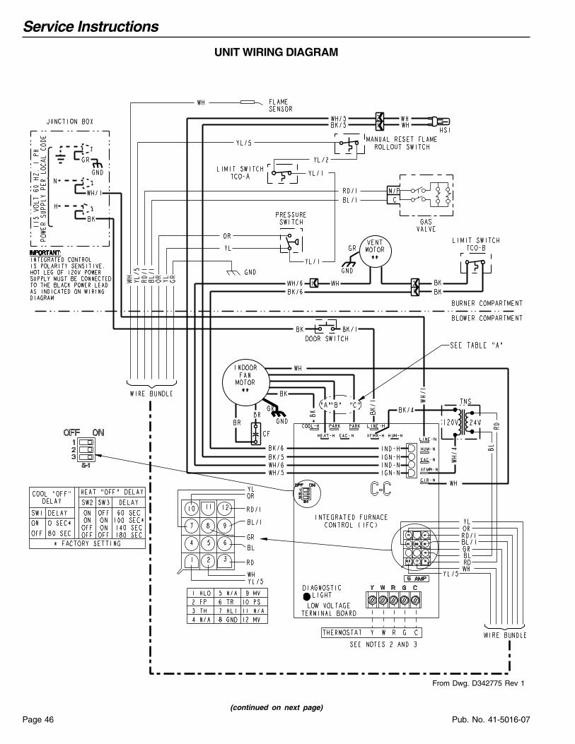
Service Instructions
Pub. No. 41-5016-07Page 46
UNIT WIRING DIAGRAM
From Dwg. D342775 Rev 1
(continued on next page)

Service Instructions
Page 47Pub. No. 41-5016-07
SCHEMATIC DIAGRAM
From Dwg. D342775 Rev 1
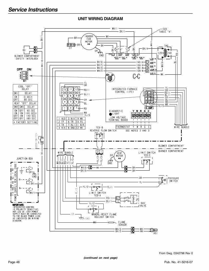
Service Instructions
Pub. No. 41-5016-07Page 48
UNIT WIRING DIAGRAM
From Dwg. D342798 Rev 0
(continued on next page)
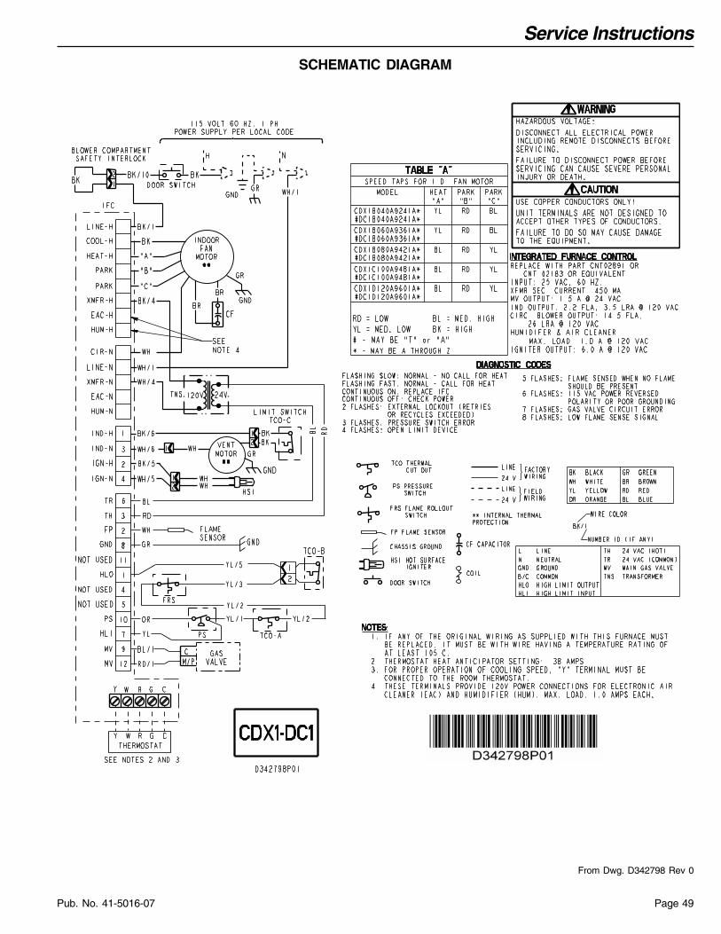
Service Instructions
Page 49Pub. No. 41-5016-07
SCHEMATIC DIAGRAM
From Dwg. D342798 Rev 0
Owner’s Information
Pub. No. 41-5016-07Page 50
WARRANTIES
As an ENERGY STAR Partner, American StandardInc., has determined that this product meets theENERGY STAR guidelines for energy efficiency.
17 26-1000-21
The limited warranties displayed in this publication and/or on ComfortSite™ may not accurately reflect the actual limited warranty that shipped with the product.
Models Less Than 20 Tons for Residential Use*
Limited WarrantyHigh EfficiencyCondensing Gas FurnaceUH3, DH3, UX2, DX2, UH2, DH2, UX1, DX1, UX1-H, DX1-H, UX, DX, UY and DY(First letter may be preceded by an “A” or “T”) (Parts Only)
This limited warranty is extended by Trane U.S. Inc., to the original purchaser of the specified models for life, under the conditions set forth below or to any succeeding owner for a period of twenty (20) years from the date of installation, as originally affixed, for the original owner. This limited warranty applies to products purchased and retained for use within the U.S.A. and Canada.
Limited WarrantyIf any part of your furnace fails because of a manufacturing defect within five (5) years from the date of original pur-chase, Warrantor will furnish without charge the required replacement part F.O.B. nearest Parts Distribution point. Any local transportation, related service labor, air filters, and diagnosis calls, are not included.
Limited Lifetime WarrantyThe primary and secondary heat exchanger, when installed to serve a single family residence or single condominium, is warranted to the original purchaser for life, provided the installation is in the original purchaser’s primary, uninter-rupted residence from the date of purchase until discovery of a defect in the primary heat exchanger or secondary heat exchanger. The heat exchanger is warranted to a successor purchaser for a period of twenty (20) years from the date of original installation of the furnace, subject to proof of original purchase. Warrantor WILL AT ITS OPTION provide either a heat exchanger including secondary heat exchanger without charge F.O.B. nearest Parts Distribution point, or allow a credit in the amount of the then current wholesale price of an equivalent heat exchanger toward the purchase price of a comparable heating unit. Any local transportation, related service labor, air filters, and diagnosis calls, are not included.
This limited warranty does not cover failure of your gas furnace if it is damaged while in your possession, damage caused by unreasonable use of the gas furnace and/or damage from failure to properly maintain the gas furnace as set forth in the Use and Care manual (see Proper Maintenance section)..
THE LIMITED WARRANTY AND LIABILITY SET FORTH HEREIN ARE IN LIEU OF ALL OTHER WAR-RANTIES AND LIABILITIES, WHETHER IN CONTRACT OR IN NEGLIGENCE, EXPRESS OR IMPLIED, IN LAW OR IN FACT, INCLUDING IMPLIED WARRANTIES OF MERCHANTABILITY AND FITNESS FOR PARTICULAR USE, AND IN NO EVENT SHALL WARRANTOR BE LIABLE FOR ANY INCIDENTAL OR CONSEQUENTIAL DAMAGES.
Some states do not allow limitations on how long an implied limited warranty lasts or do not allow the exclusion or limi-tation of incidental or consequential damages, so the above limitation or exclusion may not apply to you. This limited warranty gives you specific legal rights, and you may also have other rights which vary from state to state.
Parts will be provided by our factory organization through an authorized service organization in your area listed in the yellow pages. If you wish further help or information concerning this limited warranty, contact:
Trane P. O. Box 9010, Tyler, TX 75711-9010 Attention: Manager, Field Operations Excellence
Or visit our website: www.trane.com/residential
TW-1013-4707
* This limited warranty is for residential usage of this equipment and not applicable when this equipment is used for a commercial application. A commercial use is any application where the end purchaser uses the product for other than personal, family or household purposes.
(or "C")

Owner’s Information
Page 51Pub. No. 41-5016-07
As an ENERGY STAR Partner, American StandardInc., has determined that this product meets theENERGY STAR guidelines for energy efficiency.
Models Less Than 20 Tons for Commercial Use*
Limited WarrantyInduced Draft Gas FurnaceUC1, DC1, UX1, DX1, UX1-H, DX1-H, UX, DX, UY, DY, UD-R, DD-R, UD-RV, DD-RV, UD1-H, DD1-H, UD1, DD1, UE1, DE1, UH3, DH3, UX2, DX2, UH2, DH2, UD2 and DD2
This warranty is extended by Trane U.S. Inc., to the original purchaser and to any succeeding owner of the real prop-erty to which the Gas Furnace is originally affixed, and applies to products purchased and retained for use within the U.S.A. and Canada. There is no warranty against corrosion, erosion or deterioration.
If any part of your Gas Furnace fails because of a manufacturing defect within one year from the date of the original purchase, Warrantor will furnish without charge the required replacement part.
This limited warranty does not cover failure of your gas furnace if it is damaged while in your possession, damage caused by unreasonable use of the gas furnace and/or damage from failure to properly maintain the gas furnace as set forth in the Use and Care manual (see Proper Maintenance section).
In addition, if the steel heat exchanger fails because of a manufacturing defect within the second through twentieth year from the date of original purchase, Warrantor shall furnish without charge a replacement heat exchanger. War-rantor’s obligations and liabilities under this warranty are limited to furnishing F.O.B. Warrantor factory or warehouse replacement parts for Warrantor’s products covered under this warranty. No liability shall attach to Warrantor until products have been paid for and then liability shall be limited solely to the purchase price of the equipment under war-ranty shown to be defective.
THE WARRANTY AND LIABILITY SET FORTH HEREIN ARE IN LIEU OF ALL OTHER WARRAN-TIES AND LIABILITIES, WHETHER IN CONTRACT OR IN NEGLIGENCE, EXPRESS OR IMPLIED, IN LAW OR IN FACT, INCLUDING IMPLIED WARRANTIES OF MERCHANTABILITY AND FITNESS FOR PARTICULAR USE, AND IN NO EVENT SHALL WARRANTOR BE LIABLE FOR ANY INCIDENTAL OR CONSEQUENTIAL DAMAGES.
Some states do not allow limitations on how long an implied warranty lasts or do not allow the exclusion or limitation of incidental or consequential damages, so the above limitation or exclusion may not apply to you. This warranty gives you specific legal rights, and you may also have other rights which vary from state to state.
Trane P.O. Box 9010 Tyler, TX 75711-9010 Attention: Manager, Field Operations Excellence
TW-1012-4707
* This warranty is for commercial usage of said equipment and not applicable when the equipment is used for a residential application. Commercial use is any application where the end purchaser uses the product for other than personal, family or household purposes.
(First letter may be preceded by an “A” or “T”) (Parts Only)
(or "C")

American StandardHeating & Air Conditioning
6200 Troup Hwy.Tyler, TX 75707
Pub. No. 41-5016-07