installation & operating manual - altronic inc/vsm_plus_iom 9-14.pdf · 2.2 the vsm+ is a...
TRANSCRIPT

Installation & Operating ManualVSM+ Vibration Sensing Monitor for PLC
Form VSM+ IOM 9-14
ODVA APPROVAL PENDING

VSM+ IOM 9-14 All rights reserved © ALTRONIC, LLC 2014 2
1.0 PLC+ Function-Specific I/O Modules1.1 The PLC+ product line was developed by Altronic to allow easy integration of
engine/compressor/generator function specific I/O through Ethernet to industry standard PLCs. The PLC+ Modules are designed to seamlessly deliver efficient, hazardous area approved, cost effective I/O functions that are not normally available by off-the-shelf PLC hardware.
1.2 The PLC+ modules were designed with Rockwell Automation Control Logix
and Compact Logix controllers in mind. EtherNet/IP implemented in the PLC+ Modules, along with Modbus/TCP allow seamless communication over Ethernet to Rockwell Automation PLCs as well as a wide range of other industrial PLCs.
1.3 The PLC+ Monitors are based upon taking a time tested Altronic designed and
tested specialty I/O function such as analog and digital I/O, vibration, detonation, speed, and others and marrying it to a communications board packaged in a rugged, cost effective shock and dust-resistant package.
2.0 VSM+ Description2.1 The VSM+ Vibration Sensing Monitor is a module in the PLC+ product line. It
uses the patented vibration monitoring technique of the VSM-800 and adds an integrated Ethernet port. It is designed to protect industrial engines, compressors, and associated equipment from damage caused by excessive vibration. It accepts up to 8 industry-standard, low-cost, broadband, piezoelectric vibration sensors that are used to transform mechanical vibrations into electrical signals which are then evaluated by the VSM+. Each input channel operates independently of the other. It is designed for use as a component of a PLC+ Control Panel, or as a stand-alone product. PLC+ panels use one or more such devices for engine control and monitoring. The integral Ethernet port allows the monitored values to be communicated to a PC, PLC, or other communications device using either Modbus/TCP or EtherNet/IP protocol. These values can be displayed on an HMI display and compared to user adjustable setpoint levels for alarm and shutdown.
2.2 The VSM+ is a flexible I/O device. It is designed around the Altronic VSM-800
stand-alone Vibration Monitor. The VSM+ is functionally similar to the VSM-800 but without the LCD display and keypad and is packaged in a compact rugged rail-mount package. The VSM+ adds a built-in Ethernet communications port that allows communication to a PLC network. Therefore the VSM+ can be applied as a “Stand Alone” I/O device, as a “basic” input device, or a combination of each to a PLC. The distinction is that with a stand-alone implementation the output switches, remote lockout, reset, timers, and other functions provided by the VSM+ are utilized. The basic application uses the vibration signals from the VSM+ but all other control is done in the PLC.
2.3 The VSM+ is housed in a 4.5” x 4.25” rugged anodized aluminum case. It mounts on a DIN rail using the DIN-rail-clip on the back of the unit. Pluggable Phoenix Contact-type connectors with push-in spring-cage connectors are used for connections. A standard RJ45 connector is used for Ethernet communications. The power requirement is 10 to 32Vdc, 0.20Amp max.
2.4 For proper operation, these instructions must be adhered to strictly.
2.5 This manual does not cover every aspect of installation of the VSM+ because it is very similar to the VSM-800. For additional information that does not appear in this manual, please refer to the Installation/Operation manual VSM IOM. The VSM IOM manual can be found on the Altronic website www.altronic-llc.com
WARNING: Deviation from this installa-tion/operating manual may lead to improper operation of the monitored machine which could cause personal injury to operators or other nearby personnel.
CAUTION: The VSM vibration monitor is certified for use in Class I, Groups C & D, Division 2 hazardous locations when installed in accordance with these instructions.
The sensor input leads connected to this device operate at a low volt-age and power level and MUST NOT CONTACT any external voltage source. Damage to the system will result from connection between the input sensor leads and the ignition system or any AC or DC power source above 36 Vdc.
WARNING: The VSM+ must be config-ured prior to use.

VSM+ IOM 9-14 All rights reserved © ALTRONIC, LLC 2014 3
3.0 Mounting3.1 Mount the VSM+ inside a control panel or to a suitable flat surface. A DIN-rail-
mounting-clip on the back of the unit is used to mount the unit on a standard 35mm DIN rail. When mounting the Monitor to the DIN rail, angle the top of the unit towards the rail and slide the top of the clip over the top of the rail. Firmly push the unit towards the rail until it snaps into place. To remove, grab the Monitor firmly on the top of the unit and apply downward pressure to compress the latch spring. Rock the bottom of the unit away from the rail.
4.0 Wiring (SEE WIRING DIAGRAMS)
4.1 GENERAL Take care not to damage the insulation and take precautions against damage
from vibration, abrasion or liquids in conduits. Never run sensor, low voltage power, current loop, communications, or output switch wires in the same conduit as the ignition wiring or other high energy wiring such as AC line power, etc. Keep wires at least 12 inches away from all high voltage wiring.
Keep secondary wires to spark plugs and other high voltage wiring at least 12 inches (205mm) away from vibration sensors and their wiring.
4.2 POWER WIRING Connect the power input wires to terminals (DC+) and (DC-); power requirement
is 10 to 32Vdc, 0.20Amp max. Connect the minus terminal (DC-) to panel ground, which must be the same as the ground on the monitored device. This device must be powered from a Class 2 power supply. It is recommended that the current from the power supply to the Monitor be limited through a properly sized surge tolerant fuse or electronic breaker.
4.3 VIBRATION SENSOR WIRING
The vibration sensors generate low voltage bipolar signals in the millivolt range. Refer to form VSM IOM for mounting details. Each vibration sensor requires two wires. Use a two-conductor cable of 20-22AWG (Altronic 693134-x or equivalent) to wire the vibration sensor to the sensor input terminals on the front of the VSM+. The sensor cables should be run in rigid conduit or Sealtite/Liquidtite to protect the wires from breakage. The shield wire can be grounded on one end if it is determined that spurious electrical noise is affecting sensor output.
4.4 OUTPUT SWITCH WIRING Exceeding a setpoint value will cause the user-programmable output switch to
turn ON/OFF with respect to its common. The VSM contains two output switches. Switch 1 is typically used for alarm and switch 2 is typically used for shutdown. Output switch 1 will trip when an input value exceeds its alarm setpoint value. Output switch 2 will trip when an input value exceeds its shutdown setpoint value. These switches are solid state, form C (N/O and N/C) break-before-make contacts and are isolated from the power supply. Switch 1 is closed with the absence of power and switch 2 is open with the absence of power. The switches are rated at 32Vdc, 200mA and the N/O switch has a unique internal overload current protection circuit. If an overload occurs, the internal circuitry limits current to safe levels. When the overload is removed, the relay resumes its normal ON characteristics. These switches can be wired to engine management systems, an Altronic annunciator system or to pilot duty relays as shown by the wiring diagrams; see Figure 5.
4.5 RJ45 ETHERNET COMMUNICATIONS WIRING The VSM+ can communicate to other instruments, PC’s, or PLCs via the Ethernet
communications port. Use data grade Category 5E Shielded Twisted Pair (STP) or Unshielded Twisted-Pair (UTP) cable that has a 100Ω characteristic impedance that meets the EIA/TIA Category Five (CAT-5) wire specifications. Max wire length is 100 meters / 325 feet.
4.6 HAZARDOUS AREA OPERATION The VSM+ is CSA certified for CLASS I, DIVISION 2, GROUPS C & D areas as a
component only and is required to be installed in a suitable enclosure where the
WARNING: This monitor is OPEN type equipment that must be used within a suitable enclosure.
NOTE: Altronic HIGHLY RECOMMENDS the use of resistor spark plugs and/or spark plug leads with all digital instrumentation as a means of reduc-ing the impact of RFI (radio frequency interference) on operation.
WARNING: DO NOT connect the minus terminal directly to AN IGNITION SYS-TEM COMMON COIL GROUND ON THE ENGINE.
NOTE: The use of Category 5E STP cable (Shielded Twisted Pair) with shielded RJ45 plug connectors is strongly recommended for instal-lations in harsh industrial environ-ments and/or in the presence of strong electrical fields.

VSM+ IOM 9-14 All rights reserved © ALTRONIC, LLC 2014 4
suitability of the combination is subject to the local inspection authority having jurisdiction. The power connections to the VSM must be in accordance with the National Electrical Code and in Canada, the Canadian Electrical Code. In addition, the following requirements must be met:
1. Run the sensor wires leaving the panel in a separate conduit from all other wiring and keep them separate throughout the installation.
2. Power, input, and output wiring must have a grade of insulation capable of withstanding an AC voltage of 500 volts RMS.
3. In general, run wires in separate conduits and junction boxes from high voltage wires such as ignition, fuel valve, and other high voltage wiring.
5.0 Overview5.1 The VSM+ senses shock and vibration from the remote mounted vibration
sensors and outputs a velocity amplitude number in the range of 0 to 1023. The velocity amplitude number is unitless and in this manual is referred to as the vibration reference number.
5.3 The VSM+ vibration sensor is an automotive type accelerometer. It generates a low voltage signal proportional to vibration intensity. The sensor inputs to the VSM+ are differential and are not referenced to ground.
5.4 Each channel can be configured differently from the others with its own unique alarm and shutdown setpoint value, startup delay timer value, sensor gain value, and trip delay time value.
5.5 There are two output switches, switch 1 is for alarm and switch 2 is for shutdown. Switch 1 is normally closed and switch 2 is normally open with lack of power. These switches are isolated from ground and turn-on to switch common.
6.0 Front Panel LED Indicators6.1 POWER – When the unit is powered, the green “POWER” LED will be on.
6.2 STATUS – The status indicator is multi-purpose. It contains several “blink” patterns.
EtherNet/IP communications mode – one long, one short blink at ¼-second rate
Modbus/TCP communications mode – short blinks at ¼ second rate “wink” mode – steady short blinks at 1/8 second rate for the selected time
6.3 ETHERNET – The Ethernet port contains two LED’s that are built into the RJ45 connector. The green LINK LED will be on solid if the Ethernet port has successfully established a connection. The yellow RX/TX light signals network activity.
6.4 OUTPUT SWITCH INDICATORS – Each of the built-in output switches (SW1 and SW2) have an LED indicator. The LED turns on when the switch is activated.
7.0 Reset 7.1 Reset can be initiated in one of two ways: by pulling the remote reset terminal on
the monitor low, or by sending a reset command via communications. RESET resets the Start-Up Timer and places the output switches in the non-tripped condition.
8.0 Startup Lockout8.1 The Startup Lockout terminal on the monitor is used to lock out the Alarm and
WARNING: Do not disconnect equip-ment in Div. 2 environment unless power is switched off or the area is known to be non-hazardous.

VSM+ IOM 9-14 All rights reserved © ALTRONIC, LLC 2014 5
Shutdown output switches from tripping during machine startup when above normal vibrations may occur. The output switches are locked out or disabled when the terminal is low or grounded. For an engine compressor application this terminal can be wired to an oil pressure switch. For loss of oil pressure the switch should be grounded. When the terminal is released, (ungrounded) the Start Delay Timer for each channel commences. The output switches will remain locked-out for each individual channel until the timer for each channel ends. Each channel will become armed when the timer for that channel expires.
9.0 Alarm and Shutdown9.1 The ALARM and SHUTDOWN setpoints are high setpoints. If the vibration level
goes above the alarm setpoint, switch #1 will activate. If the vibration level goes above the shutdown setpoint, switch #2 will activate. Each setpoint can be set anywhere within the range of the monitor, or off.
10.0 Protocols10.1 The PLC+ Monitors support EtherNet/IP (Ethernet Industrial Protocol) and
Modbus/TCP (Modbus over TCP/IP).
10.2 EtherNet/IP – EtherNet/IP is a communication protocol developed and used by Rockwell Automation for use in their Allen Bradley brand PLCs. It is managed by Open DeviceNet Vendors Association (ODVA) (www.odva.org) and is designed for use in process control and other industrial automation applications. Some other vendors using EtherNet/IP are Omron, Schneider Electric, Harting, Phoenix Contact, Opto 22, Wago Corporation, and Yaskawa. EtherNet/IP uses objects to communicate to and from the PLC+ Monitors and the PLC. An object model is a collection of related data values and common elements of the PLC+ monitor. The object model is listed at the end of this manual.
10.3 Modbus/TCP – Modbus/TCP is Modbus over Ethernet. It is very similar to Modbus RTU. The Modbus registers are the same. The memory map of the Modbus registers are listed at the end of this manual.
11.0 EDS File (Electronic Data Sheet)11.1 The EDS file is used for Monitor configuration and to commission it on an EtherNet/
IP network. It is an ASCII text file that describes the Monitors’ device type, product revision, and its configurable parameters on the EtherNet/IP network.
11.2 An EDS file for the VSM+ can be found enclosed on the media with this document and on the Altronic ftp site; it may also be downloaded from the onboard web page.
12.0 Embedded Web Server12.1 Each PLC+ Monitor has a built-in web server that allows it to be set up. The
embedded web server can be used to view and set the network settings and the protocol settings. For connection details see wiring diagram at the end of this manual.
12.2 The PLC+ Monitors support Auto MDI/MDI-X crossover. A straight-through Ethernet cable may be used to connect the PC to the PLC+ Monitor. A straight-through connection through an Ethernet switch or hub on a network may also be used.
12.3 Once connected and powered, open your web browser and type the IP address assigned to the Monitor in the “Address” bar; http://10.1.100.100 for example. The Monitors home page will be displayed.
NOTE: The default parameters are:Static IP Address: 10.1.100.100Subnet Mask:255.255.255.0Protocol Setting: EtherNet/IP

VSM+ IOM 9-14 All rights reserved © ALTRONIC, LLC 2014 6
12.4 Home Page – The Home Page will show the current firmware version, Network Settings, Protocol Settings and allows execution of the “Wink” mode.
Default Settings are shown
Status:
Up Time – The Up Time is the time between power cycles. Firmware Version – The Firmware Version is the revision level and the date it
was compiled CIP Library – The CIP Library is the personality code of the product and rev level.
Ethernet:
IP Address – The IP Address is a node identification number for the device on the network. The current IP address is shown.
IP Mode – IP Mode shows the current Static, DHCP, BootP, or AutoIP IP address assignment type.
MAC Address – The MAC Address is the unique Hardware identifier of the Monitor assigned by the factory.
Protocol Setting – Shows the current protocol; either EtherNet/IP or Modbus/TCP. Wink Mode – The “wink” mode is used to identify a Monitor in the network.
When the wink mode is commanded the “STATUS” LED on the Monitor with the displayed IP address, will blink with short blinks at a rate of 1/8 second. This can be used by the integrator or technician to identify which unit is being talked to. The number of seconds the unit will “wink” for can be selected from 1 to 60 seconds.
VSM+ IOM 9-14 All rights reserved © ALTRONIC, LLC 2014 7
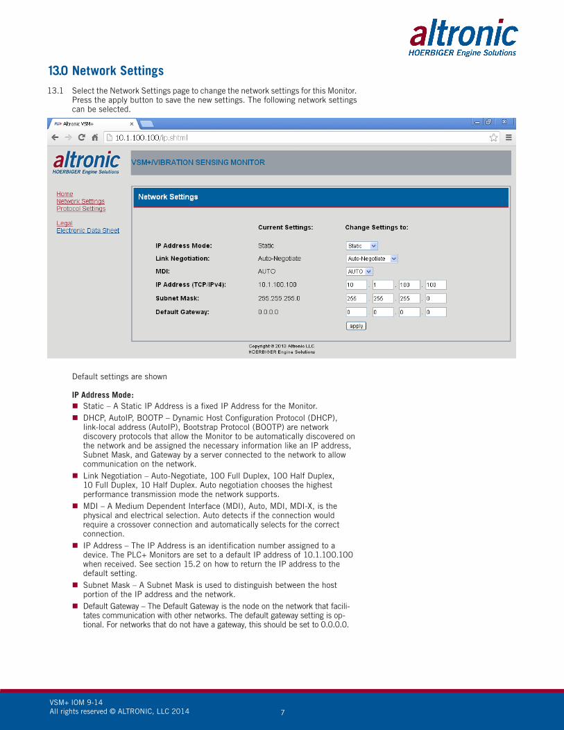
13.0 Network Settings13.1 Select the Network Settings page to change the network settings for this Monitor.
Press the apply button to save the new settings. The following network settings can be selected.
Default settings are shown
IP Address Mode: Static – A Static IP Address is a fixed IP Address for the Monitor. DHCP, AutoIP, BOOTP – Dynamic Host Configuration Protocol (DHCP),
link-local address (AutoIP), Bootstrap Protocol (BOOTP) are network discovery protocols that allow the Monitor to be automatically discovered on the network and be assigned the necessary information like an IP address, Subnet Mask, and Gateway by a server connected to the network to allow communication on the network.
Link Negotiation – Auto-Negotiate, 100 Full Duplex, 100 Half Duplex, 10 Full Duplex, 10 Half Duplex. Auto negotiation chooses the highest performance transmission mode the network supports.
MDI – A Medium Dependent Interface (MDI), Auto, MDI, MDI-X, is the physical and electrical selection. Auto detects if the connection would require a crossover connection and automatically selects for the correct connection.
IP Address – The IP Address is an identification number assigned to a device. The PLC+ Monitors are set to a default IP address of 10.1.100.100 when received. See section 15.2 on how to return the IP address to the default setting.
Subnet Mask – A Subnet Mask is used to distinguish between the host portion of the IP address and the network.
Default Gateway – The Default Gateway is the node on the network that facili-tates communication with other networks. The default gateway setting is op-tional. For networks that do not have a gateway, this should be set to 0.0.0.0.
VSM+ IOM 9-14 All rights reserved © ALTRONIC, LLC 2014 8
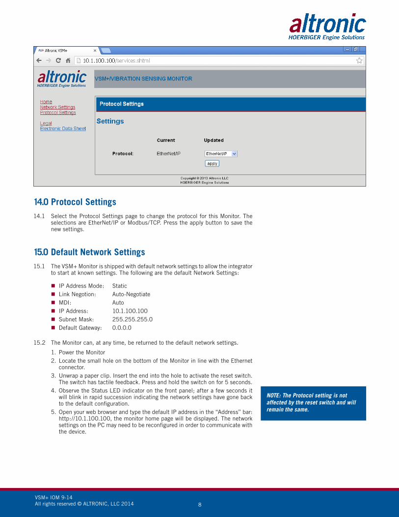
14.0 Protocol Settings14.1 Select the Protocol Settings page to change the protocol for this Monitor. The
selections are EtherNet/IP or Modbus/TCP. Press the apply button to save the new settings.
15.0 Default Network Settings15.1 The VSM+ Monitor is shipped with default network settings to allow the integrator
to start at known settings. The following are the default Network Settings:
IP Address Mode: Static Link Negotion: Auto-Negotiate MDI: Auto IP Address: 10.1.100.100 Subnet Mask: 255.255.255.0 Default Gateway: 0.0.0.0
15.2 The Monitor can, at any time, be returned to the default network settings.
1. Power the Monitor2. Locate the small hole on the bottom of the Monitor in line with the Ethernet
connector.3. Unwrap a paper clip. Insert the end into the hole to activate the reset switch.
The switch has tactile feedback. Press and hold the switch on for 5 seconds. 4. Observe the Status LED indicator on the front panel; after a few seconds it
will blink in rapid succession indicating the network settings have gone back to the default configuration.
5. Open your web browser and type the default IP address in the “Address” bar: http://10.1.100.100, the monitor home page will be displayed. The network settings on the PC may need to be reconfigured in order to communicate with the device.
NOTE: The Protocol setting is not affected by the reset switch and will remain the same.

VSM+ IOM 9-14 All rights reserved © ALTRONIC, LLC 2014 9
16.0 Configuring the VSM+
16.1 Since operating conditions differ, the VSM+ Vibration Sensing Monitor must be customized for each application. Each parameter is described below. The configuration parameter values must be carefully chosen.
16.2 SENSOR GAIN The SENSOR GAIN adjustment is used to increase or decrease the signal gain
from the sensor. If the signal from the sensor results in the reading being too low or too high with the current gain value, the gain can be used to bring the reading into the desired range. Each channel can be individually set from 64 (a small gain value) to 0 (a large gain value). A value of 64 maps to a gain value of .111. A value of 0 maps to a gain value of 2.0. Consult the gain chart in the Modbus table section for further information. If possible, it is suggested to use a similar gain value for all channels. By using a similar gain value for all channels, with respect to each other, a larger vibration will be displayed as a larger value and a smaller vibration will be displayed as a smaller value.
16.3 TRIP DELAY TIME The TRIP DELAY TIME is used to delay tripping the output switches during a
sudden momentary increase in a monitored vibration level. Should a sudden momentary increase in a vibration level occur caused by a one-time impact that is shorter in duration than the Trip Delay Time the monitor will show the impact but the output switches will not trip. Harmful vibrations are typically of the repeating type and will last longer than the Trip Delay Time. Each channel can be individually set from 0 to 15 seconds.
16.4 OUTPUT SWITCHES There are two output switches, typically switch 1 is for ALARM and switch 2
is for SHUTDOWN. Each switch can be set to be active or inactive, shelf or failsafe, and latching or non-latching. Shelf state is when the outputs are in the same condition with no faults as when unpowered; failsafe is when they are opposite. In non-latching mode, the output switch changes state when the setpoints come out of violation; in latching mode, a reset event is required to clear the switches from the tripped state. Unpowered states for the switches are closed for SW 1 and open for SW 2.
16.5 OUTPUT SWITCH #1 Output switch #1 is designed to be used as an alarm. The switch is activated
when an alarm setpoint value is violated for any monitored sensor.
16.5.1 ACTIVE If the data value is 1, then output switch #1 will activate. If the data value
is 0, then output switch #1 will not activate.
16.5.2 SHELF OR FAILSAFE STATE Switch #1 is a closed switch when in the shelf state (with the absence of
power). The switch can be configured for either failsafe or shelf state. When set to Shelf state, the output switch will be closed when no setpoint values are violated. When set to Failsafe, the output switch will be open when no setpoint values are violated. If set to Failsafe and the power is lost to the Monitor, the output switch will change states (it will close).
16.5.3 NONLATCH OR LATCH Switch #1 can be configured for latching or non-latching. When set
to Latch the switch will stay tripped continuously until it is reset by the active communication protocol, the power is cycled, or the reset terminal is grounded. When set to Non latch the switch will stay tripped if any channel’s reference number is above the setpoint values. It will automatically reset when the values have returned to within the limits plus the hysteresis time set. Default is 5 seconds.
16.5.4 TRIP ON BAD SENSOR SETPOINT A bad sensor will cause switch 1 or 2 to activate if enabled (default switch 1)
when the vibration level drops below the bad sensor set point. Either output switch #1 or #2 can be configured to take action.
NOTE: The VSM+ vibration monitor must be configured prior to use.
WARNING: Excessive vibration for an extended time period can result in equipment damage and/or personal injury. adjust the trip delay time for the shortest required duration.

VSM+ IOM 9-14 All rights reserved © ALTRONIC, LLC 2014 10
16.6 OUTPUT SWITCH #2 Output Switch #2 is designed to be used as a shutdown output. The switch is
activated when a shutdown setpoint value has been violated. The switch can be connected to an Altronic Annunciator System, an ignition low voltage shutdown input, or to pilot-duty relays.
16.6.1 ACTIVE If the data value is 1, then output switch #2 will activate. If the data value is
0, then output switch #2 will not activate.
16.6.2 SHELF or FAILSAFE STATE Switch #2 is an open switch when in the shelf state (with the absence of
power). The switch can be configured for either Failsafe or Shelf state. When set to Shelf state, the output switch will be open for normal run conditions. When set to Failsafe, the output switch will be closed for normal run conditions. If set to Failsafe and the power is lost to the Monitor, the output switch will change states (it will open).
16.6.3 NON LATCH or LATCH Switch #2 can be configured for latching or non-latching. When set
to Latch, the switch will stay tripped continuously until it is reset by the active communication protocol, the power is cycled, or the reset terminal is grounded. When set to non latch, the switch will stay tripped if any channel’s reference number is above the setpoint value. It will automatically reset when the value has returned to within the limits plus the hysteresis time set. The default hysteresis time is 5 seconds.
17.0 Available Protocols in the VSM+, EtherNet/IP and Modbus/TCP
17.1 The VSM+ Vibration Sensing Monitor is part of a system designed to easily interface to popular PLCs, SCADA systems and computers. The VSM+ has two user-selectable communication protocols, EtherNet/IP and Modbus/TCP. The built-in WEB SERVER is used to select the protocol. See section 12.0 EMBEDDED WEB SERVER to select the protocol.
17.2 EtherNet/IP – Ethernet Industrial Protocol is Ethernet combined with an industrial application layer protocol targeted to industrial PLCs. The EtherNet/IP protocol is used by Allen Bradley in their Compact Logix and Control Logix PLCs. The EtherNet/IP is used in many other PLC manufacturers as well.
17.3 The data for EtherNet/IP is arranged as a collection of objects. Objects divide the functionality of a device into logically related subsets. This collection of related data values and common elements of the device make up its object model.

VSM+ IOM 9-14 All rights reserved © ALTRONIC, LLC 2014 11
18.0 EtherNet/IP Object Models18.1 The following Objects are used in the VSM+.
OBJECT (ID) TYPE
Identity (01h) Required
Message Router (02h) Required
Assembly (04h) Device-specific
Connection Manager (06h) Required
TCP Object (F5h) Required
Ethernet Link Object (F6h) Required
QoS (48h) Pre-defined
Parameter (0Fh) Pre-defined
Parameter Group (10h) Pre-defined
Group (12h) Pre-defined
File (37h) Pre-defined
Sensor (68h) Vendor Specific
VSM (69h) Vendor Specific
Log (70h) Vendor Specific
18.2 Identity Object (01h – 1 instance) The identity object provides identification of, and general information about, the VSM+.
ATTR ID NAME DATATYPE
DATAVALUE
AccessRULE
Class Attributes
1 Revision UINT 1 GET
Instance Attributes
1 Vendor Number UINT 1250DEC GET
2 Device Type, Generic UINT 2bHEX GET
3 Product Code Number UINT 27DAHEX GET
4 Product Major RevisionProduct Minor Revision
USINTUSINT
0230
GET
5 Status Word(see definition below)
WORD See Below GET
6 Product Serial Number(unit mac address)
UDINT Unique 32Bit Val
GET
7 Product Name Structure of: Product Name SizeProduct Name String
USINTUSINT[0-32]
7“VSMPlus”
GET
Status Word
Bit Bit = 0 Bit = 1
0 No I/O Connection I/O Connection Allocated
1-15 Unused Unused
CHART CONTINUES…
VSM+ IOM 9-14 All rights reserved © ALTRONIC, LLC 2014 12
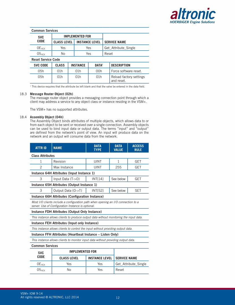
Common Services
SVCCODE
IMPLEMENTED FOR
SERVICE NAMECLASS LEVEL INSTANCE LEVEL
0EHEX Yes Yes Get_Attribute_Single
05HEX No Yes Reset
Reset Service Code
SVC CODE CLASS INSTANCE DATA1 DESCRIPTION
05h 01h 01h 00h Force software reset.
05h 01h 01h 01h Reload factory settingsand reset.
1 This device requires that the attribute be left blank and that the valve be entered in the data field.
18.3 Message Router Object (02h) The message router object provides a messaging connection point through which a
client may address a service to any object class or instance residing in the VSM+.
The VSM+ has no supported attributes.
18.4 Assembly Object (04h) The Assembly Object binds attributes of multiple objects, which allows data to or
from each object to be sent or received over a single connection. Assembly objects can be used to bind input data or output data. The terms ”input” and ”output” are defined from the network’s point of view. An input will produce data on the network and an output will consume data from the network.
ATTR ID NAME DATATYPE
DATAVALUE
ACCESSRULE
Class Attributes
1 Revision UINT 1 GET
2 Max Instance UINT 255 GET
Instance 64H Attributes (Input Instance 1)
3 Input Data (T->O) INT[14] See below GET
Instance 65H Attributes (Output Instance 1)
3 Output Data (O->T) INT[52] See below SET
Instance 66H Attributes (Configuration Instance)
Most I/O clients include a configuration path when opening an I/O connection to a server. Use of Configuration Instance is optional.
Instance FDH Attributes (Output Only Instance)
This instance allows clients to produce output data without monitoring the input data.
Instance FEH Attributes (Input only Instance)
This instance allows clients to control the input without providing output data.
Instance FFH Attributes (Heartbeat Instance – Listen Only)
This instance allows clients to monitor input data without providing output data.
Common Services
SVCCODE
IMPLEMENTED FOR
SERVICE NAMECLASS LEVEL INSTANCE LEVEL
0EHEX Yes Yes Get_Attribute_Single
05HEX No Yes Reset

VSM+ IOM 9-14 All rights reserved © ALTRONIC, LLC 2014 13
18.5 Input Assembly Data “Target to Originator” (T->O)
INDEX NAME MIN MAX EQUIV MODBUSREGISTER
0 Vibration Channel 1 0 1023 30015
1 Vibration Channel 2 0 1023 30016
2 Vibration Channel 3 0 1023 30017
3 Vibration Channel 4 0 1023 30018
4 Vibration Channel 5 0 1023 30019
5 Vibration Channel 6 0 1023 30020
6 Vibration Channel 7 0 1023 30021
7 Vibration Channel 8 0 1023 30022
8 Supply Voltage (*100) 700 3500 30010
9.0 Reserved 0 1 10001
9.1 Reserved 0 1 10002
9.2 SW1 Active 0 1 10003
9.3 SW2 Active 0 1 10004
9.4 Reserved 0 1 10005
9.5 Reserved 0 1 10006
9.6 Reserved 0 1 10007
9.7 Reserved 0 1 10008
9.8 CAL R/W 0 1 10009
9.9 Watchdog 0 1 10010
9.10 Reset 0 1 10011
9.11 Reserved 0 1 10012
9.12 Startup Locked Out 0 1 10013
9.13 Alarm 0 1 10014
9.14 Reserved 0 1 10015
9.15 Reserved 0 1 10016
10.0 Bad Sensor 1 0 1 10017
10.1 Bad Sensor 2 0 1 10018
10.2 Bad Sensor 3 0 1 10019
10.3 Bad Sensor 4 0 1 10020
10.4 Bad Sensor 5 0 1 10021
10.5 Bad Sensor 6 0 1 10022
10.6 Bad Sensor 7 0 1 10023
10.7 Bad Sensor 8 0 1 10024
10.8 Reserved 0 1 10025
10.9 Reserved 0 1 10026
10.10 Reserved 0 1 10027
10.11 Reserved 0 1 10028
10.12 Reserved 0 1 10029
10.13 Reserved 0 1 10030
10.14 Reserved 0 1 10031
CHART CONTINUES…

VSM+ IOM 9-14 All rights reserved © ALTRONIC, LLC 2014 14
INDEX NAME MIN MAX EQUIV MODBUSREGISTER
10.15 Reserved 0 1 10032
11.0 Critical High 1 0 1 10033
11.1 Critical High 2 0 1 10034
11.2 Critical High 3 0 1 10035
11.3 Critical High 4 0 1 10036
11.4 Critical High 5 0 1 10037
11.5 Critical High 6 0 1 10038
11.6 Critical High 7 0 1 10039
11.7 Critical High 8 0 1 10040
11.8 Reserved 0 1 10041
11.9 Reserved 0 1 10042
11.10 Reserved 0 1 10043
11.11 Reserved 0 1 10044
11.12 Reserved 0 1 10045
11.13 Reserved 0 1 10046
11.14 Reserved 0 1 10047
11.15 Reserved 0 1 10048
12.0 Vibration High 1 0 1 10049
12.1 Vibration High 2 0 1 10050
12.2 Vibration High 3 0 1 10051
12.3 Vibration High 4 0 1 10052
12.4 Vibration High 5 0 1 10053
12.5 Vibration High 6 0 1 10054
12.6 Vibration High 7 0 1 10055
12.7 Vibration High 8 0 1 10056
12.8 Reserved 0 1 10057
12.9 Reserved 0 1 10058
12.10 Reserved 0 1 10059
12.11 Reserved 0 1 10060
12.12 Reserved 0 1 10061
12.13 Reserved 0 1 10062
12.14 Reserved 0 1 10063
12.15 Reserved 0 1 10064
13.0 Channel Armed 1 0 1 10065
13.1 Channel Armed 2 0 1 10066
13.2 Channel Armed 3 0 1 10067
13.3 Channel Armed 4 0 1 10068
13.4 Channel Armed 5 0 1 10069
13.5 Channel Armed 6 0 1 10070
13.6 Channel Armed 7 0 1 10071
13.7 Channel Armed 8 0 1 10072
13.8 Reserved 0 1 10073

VSM+ IOM 9-14 All rights reserved © ALTRONIC, LLC 2014 15
INDEX NAME MIN MAX EQUIV MODBUSREGISTER
13.9 Reserved 0 1 10074
13.10 Reserved 0 1 10075
13.11 Reserved 0 1 10076
13.12 Reserved 0 1 10077
13.13 Reserved 0 1 10078
13.14 Reserved 0 1 10079
13.15 Reserved 0 1 10080
14 Communication Status1 -32767 32767 Not Applicable
15.0 Switch 1 Control Echo 0 1 00001
15.1 Switch 2 Control Echo 0 1 00002
15.2 Reserved 0 1 00003
15.3 Reserved 0 1 00004
15.4 Reserved 0 1 00005
15.5 Switch 1 Enable Echo 0 1 00006
15.6 Switch 1 Failsafe Echo 0 1 00007
15.7 Switch 1 Latching Echo 0 1 00008
15.8 Bad Sensor Switch Select Echo 0 1 00009
15.9 Switch 2 Enable Echo 0 1 00010
15.10 Switch 2 Failsafe Echo 0 1 00011
15.11 Switch 2 Latching Echo 0 1 00012
15.12 Reserved 0 1 00013
15.13 Reserved 0 1 00014
15.14 Reserved 0 1 00015
15.15 Startup Lockout Echo 0 1 00016
1 Internal system diagnostic data
18.6 Output Assembly Data “Originator to Target” (O->T)
INDEX NAME MIN MAX DEFAULT EQUIV MODBUSREGISTER
0 Gain 1 0 63 14 40041
1 Gain 2 0 63 14 40061
2 Gain 3 0 63 14 40081
3 Gain 4 0 63 14 40101
4 Gain 5 0 63 14 40121
5 Gain 6 0 63 14 40141
6 Gain 7 0 63 14 40161
7 Gain 8 0 63 14 40181
8 Lag Filter 1 255 240 40013
9 Status Control1 -32767 32768 0 Not Applicable
10.0 Switch 1 Control 0 1 0 00001
10.1 Switch 2 Control 0 1 0 00002
CHART CONTINUES…
VSM+ IOM 9-14 All rights reserved © ALTRONIC, LLC 2014 16
INDEX NAME MIN MAX DEFAULT EQUIV MODBUSREGISTER
10.2 Reserved 0 1 0 00003
10.3 Reserved 0 1 0 00004
10.4 Reserved 0 1 0 00005
10.5 Switch 1 Enable 0 1 0 00006
10.6 Switch 1 Failsafe 0 1 0 00007
10.7 Switch 1 Latching 0 1 0 00008
10.8 Bad Sensor Switch Select 0 1 0 00009
10.9 Switch 2 Enable 0 1 0 00010
10.10 Switch 2 Failsafe 0 1 1 00011
10.11 Switch 2 Latching 0 1 0 00012
10.12 Reserved 0 1 0 00013
10.13 Reserved 0 1 0 00014
10.14 Reserved 0 1 0 00015
10.15 Startup Lockout 0 1 0 00016 1 Internal system diagnostic data
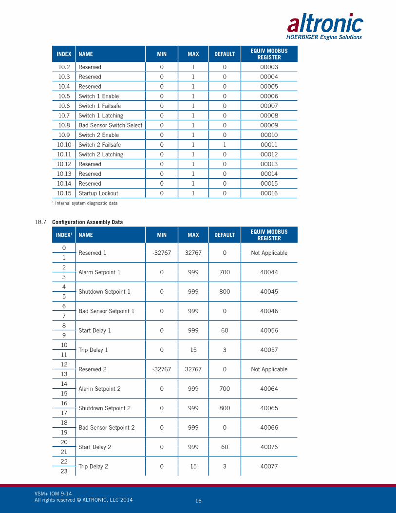
18.7 Configuration Assembly Data
INDEX1 NAME MIN MAX DEFAULT EQUIV MODBUSREGISTER
0Reserved 1 -32767 32767 0 Not Applicable
1
2Alarm Setpoint 1 0 999 700 40044
3
4Shutdown Setpoint 1 0 999 800 40045
5
6Bad Sensor Setpoint 1 0 999 0 40046
7
8Start Delay 1 0 999 60 40056
9
10Trip Delay 1 0 15 3 40057
11
12Reserved 2 -32767 32767 0 Not Applicable
13
14Alarm Setpoint 2 0 999 700 40064
15
16Shutdown Setpoint 2 0 999 800 40065
17
18Bad Sensor Setpoint 2 0 999 0 40066
19
20Start Delay 2 0 999 60 40076
21
22Trip Delay 2 0 15 3 40077
23

VSM+ IOM 9-14 All rights reserved © ALTRONIC, LLC 2014 17
INDEX1 NAME MIN MAX DEFAULT EQUIV MODBUSREGISTER
24Reserved 3 -32767 32767 0 Not Applicable
25
26Alarm Setpoint 3 0 999 700 40084
27
28Shutdown Setpoint 3 0 999 800 40085
29
30Bad Sensor Setpoint 3 0 999 0 40086
31
32Start Delay 3 0 999 60 40096
33
34Trip Delay 3 0 15 3 40097
35
36Reserved 4 -32767 32767 0 Not Applicable
37
38Alarm Setpoint 4 0 999 700 40104
39
40Shutdown Setpoint 4 0 999 800 40105
41
42Bad Sensor Setpoint 4 0 999 0 40106
43
44Start Delay 4 0 999 60 40116
45
46Trip Delay 4 0 15 3 40117
47
48Reserved 5 -32767 32767 0 Not Applicable
49
50Alarm Setpoint 5 0 999 700 40124
51
52Shutdown Setpoint 5 0 999 800 40125
53
54Bad Sensor Setpoint 5 0 999 0 40126
55
56Start Delay 5 0 999 60 40136
57
58Trip Delay 5 0 15 3 40137
59
60Reserved 6 -32767 32767 0 Not Applicable
61
62Alarm Setpoint 6 0 999 700 40144
63
CHART CONTINUES…

VSM+ IOM 9-14 All rights reserved © ALTRONIC, LLC 2014 18
INDEX1 NAME MIN MAX DEFAULT EQUIV MODBUSREGISTER
64Shutdown Setpoint 6 0 999 800 40145
65
66Bad Sensor Setpoint 6 0 999 0 40146
67
68Start Delay 6 0 999 60 40156
69
70Trip Delay 6 0 15 3 40157
71
72Reserved 7 -32767 32767 0 Not Applicable
73
74Alarm Setpoint 7 0 999 700 40164
75
76Shutdown Setpoint 7 0 999 800 40165
77
78Bad Sensor Setpoint 7 0 999 0 40166
79
80Start Delay 7 0 999 60 40176
81
82Trip Delay 7 0 15 3 40177
83
84Reserved 8 -32767 32767 0 Not Applicable
85
86Alarm Setpoint 8 0 999 700 40184
87
88Shutdown Setpoint 8 0 999 800 40185
89
90Bad Sensor Setpoint 8 0 999 0 40186
91
92Start Delay 8 0 999 60 40196
93
94Trip Delay 8 0 15 3 40197
95
96Number of Channels 1 8 8 40014
97
98Switch Hysteresis Time 0 15 3 40016
99 1 Actual values are INT unless otherwise specified, and can be directly copied from a corresponding UDT.
18.8 Connection Manager Object (06h) This object is used for connection and connectionless communication, including
establishing connections across multiple subnets.

VSM+ IOM 9-14 All rights reserved © ALTRONIC, LLC 2014 19
18.9 TCP/IP Interface Object (F5h – 1 instance) The TCP/IP Interface Object provides the mechanism to configure a device’s TCP/IP network interface. Examples of configurable
items include the device’s IP Address, Network Mask, and Gateway Address.
ATTR ID NAME DATATYPE
DATAVALUE
AccessRULE
Class Attributes
1 Revision UINT 1 GET
Instance Attributes
1 Status1 DWORD 1 GET
2 Configuration Capability2 UINT[] 5 GET
3 Configuration Control3 0 GET
4 Physical Link Object4- GET
A Structure of:
Path Size UINT 2
Path Array ofWORD
20F6H..2401H
5 Interface Configuration5 GET
A Structure of:
IP Address UDINT 0
Network Mask UDINT 0
Gateway Address UDINT 0
Name Server UDINT 0
Name Server 2 UDINT 0
Domain Name Size UINT 0
Domain Name STRING 0
6 Host Name6 GET
A Structure of:
Host Name Size UINT 0
Host Name STRING 0
Common Services
SVCCODE
IMPLEMENTED FOR
SERVICE NAMECLASS LEVEL INSTANCE LEVEL
0EHEX Yes Yes Get_Attribute_Single
10HEX No Yes Set_Attribute_Single
1 See section 5-3.2.2.1 of “Volume 2: EtherNet/IP Adaptation of CIP™” from ODVA for more details on this attribute.2 See section 5-3.2.2.2 of “Volume 2: EtherNet/IP Adaptation of CIP™” from ODVA for more details on this attribute.3 See section 5-3.2.2.3 of “Volume 2: EtherNet/IP Adaptation of CIP™” from ODVA for more details on this attribute.4 See section 5-3.2.2.4 of “Volume 2: EtherNet/IP Adaptation of CIP™” from ODVA for more details on this attribute.5 See section 5-3.2.2.5 of “Volume 2: EtherNet/IP Adaptation of CIP™” from ODVA for more details on this attribute.
6 See section 5-3.2.2.6 of “Volume 2: EtherNet/IP Adaptation of CIP™” from ODVA for more details on this attribute.

VSM+ IOM 9-14 All rights reserved © ALTRONIC, LLC 2014 20
18.10 EtherNet Link Object (F6h – 1 instance) The Ethernet Link Object maintains link-specific counters and status information
for an IEEE 802.3 communications interface.
ATTR ID NAME DATATYPE
DATAVALUE
ACCESSRULE
Class Attributes
1 Revision UINT 1 GET
Instance Attributes
1 Interface Speed1 UDINT 100(default)
GET
2 Interface Flags2 DWORD 3(default)
GET
3 Physical Address3 USINTArray[6]
0default)
GET
Common Services
SVCCODE
IMPLEMENTED FOR
CLASS LEVEL INSTANCE LEVEL SERVICE NAME
0EHEX Yes Yes Get_Attribute_Single
1 See section 5-4.2.2.2 of “Volume 2: EtherNet/IP Adaptation of CIP™” from ODVA for more details on this attribute.
2 See section 5-4.2.2.1 of “Volume 2: EtherNet/IP Adaptation of CIP™” from ODVA for more details on this attribute.
3 See section 5-4.2.2.3 of “Volume 2: EtherNet/IP Adaptation of CIP™” from ODVA for more details on this attribute.
18.11 QoS Object (48h – 1 instance) The QoS Object provides a means to configure certain QoS-related behaviors in
EtherNet/IP devices.
ATTR ID NAME DATATYPE
DATAVALUE
ACCESSRULE
Class Attributes
1 Revision UINT 1 GET
Instance Attributes
4 DSCP Urgent USINT 1 GET/SET
5 DSCP Scheduled USINT 1 GET/SET
6 DSCP High USINT 1 GET/SET
7 DSCP Low USINT 1 GET/SET
8 DSCP Explicit USINT 1 GET/SET
Common Services
SVCCODE
IMPLEMENTED FOR
CLASS LEVEL INSTANCE LEVEL SERVICE NAME
0EHEX Yes Yes Get_Attribute_Single
10HEX No Yes Get_Attribute_Single
1 See section 5-6.4.2 of “Volume 2: EtherNet/IP Adaptation of CIP™” from ODVA for more details on these attributes.
VSM+ IOM 9-14 All rights reserved © ALTRONIC, LLC 2014 21
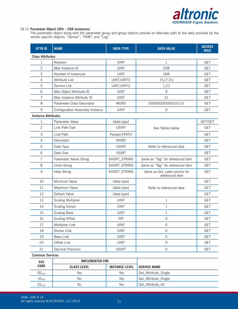
18.12 Parameter Object (0Fh – 208 instances) The parameter object along with the parameter group and group objects provide an alternate path to the data provided by the
vendor specific objects: “Sensor”, “VSM”, and “Log”.
ATTR ID NAME DATA TYPE DATA VALUE ACCESSRULE
Class Attributes
1 Revision UINT 1 GET
2 Max Instance ID UINT 208 GET
3 Number of Instances UINT 208 GET
4 Attribute List UINT,UINT[] 15,[7-21] GET
5 Service List UINT,UINT[] 1,[1] GET
6 Max Object Attribute ID UINT 9 GET
7 Max Instance Attribute ID UINT 21 GET
8 Parameter Class Descriptor WORD 0000000000001011b GET
9 Configuration Assembly Instance UINT 0 GET
Instance Attributes
1 Parameter Value [data type]
See Tables below
GET/SET
2 Link Path Size USINT GET
3 Link Path Packed EPATH GET
4 Descriptor WORD 1 GET
5 Data Type USINT Refer to referenced data GET
6 Data Size USINT GET
7 Parameter Name String SHORT_STRING Same as “Tag” for referenced item GET
8 Units String SHORT_STRING Same as “Tag” for referenced item GET
9 Help String SHORT_STRING Same as Get_Label service for referenced item
GET
10 Minimum Value [data type]
Refer to referenced data
GET
11 Maximum Value [data type] GET
12 Default Value [data type] GET
13 Scaling Multiplier UINT 1 GET
14 Scaling Divisor UINT 1 GET
15 Scaling Base UINT 1 GET
16 Scaling Offset INT 0 GET
17 Multiplier Link UINT 0 GET
18 Divisor Link UINT 0 GET
19 Base Link UINT 0 GET
20 Offset Link UINT 0 GET
21 Decimal Precision USINT 0 GET
Common Services
SVCCODE
IMPLEMENTED FOR
SERVICE NAMECLASS LEVEL INSTANCE LEVEL
0EHEX Yes Yes Get_Attribute_Single
10HEX No Yes Get_Attribute_Single
01HEX No Yes Get_Attribute_All

VSM+ IOM 9-14 All rights reserved © ALTRONIC, LLC 2014 22
18.13 “Sensor” Object Parameter Mapping (Group Instance 1) Instance (Parameter Group Instance)
Attribute 1 (1) 2 (2) 3 (3) 4 (4) 5 (5) 6 (6) 7 (7) 8 (8)
1 1 19 37 55 73 91 109 127
2 2 20 38 56 74 92 110 128
3 3 21 39 57 75 93 111 129
4 4 22 40 58 76 94 112 130
5 5 23 41 59 77 95 113 131
6 6 24 42 60 78 96 114 132
7 7 25 43 61 79 97 115 133
8 8 26 44 62 80 98 116 134
9 9 27 45 63 81 99 117 135
10 10 28 46 64 82 100 118 136
11 11 29 47 65 83 101 119 137
12 12 30 48 66 84 102 120 138
13 13 31 49 67 85 103 121 139
14 14 32 50 68 86 104 122 140
15 15 33 51 69 87 105 123 141
16 16 34 52 70 88 106 124 142
17 17 35 53 71 89 107 125 143
18 18 36 54 72 90 108 126 144
18.14 “VSM” Object Parameter Mapping
Instance (Parameter Group Instance)
Attribute 1 (9)
1 145
2 146
3 147
4 148
5 149
6 150
7 151
8 152
9 153
10 154
11 155
12 156
13 157
14 158
15 159
16 160
17 161
18 162
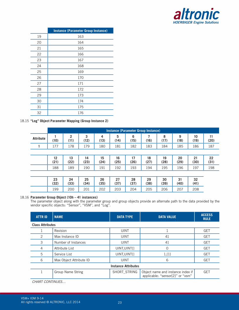
VSM+ IOM 9-14 All rights reserved © ALTRONIC, LLC 2014 23
Instance (Parameter Group Instance)
19 163
20 164
21 165
22 166
23 167
24 168
25 169
26 170
27 171
28 172
29 173
30 174
31 175
32 176
18.15 “Log” Object Parameter Mapping (Group Instance 2)
Instance (Parameter Group Instance)
Attribute 1(10)
2(11)
3(12)
4(13)
5 (14)
6(15)
7(16)
8(17)
9(18)
10(19)
11(20)
1 177 178 179 180 181 182 183 184 185 186 187
12(21)
13(22)
14(23)
15(24)
16(25)
17(26)
18(27)
19(28)
20(29)
21(30)
22(31)
188 189 190 191 192 193 194 195 196 197 198
23(32)
24(33)
25(34)
26(35)
27(37)
28(37)
29(38)
30(39)
31(40)
32(41)
199 200 201 202 203 204 205 206 207 208
18.16 Parameter Group Object (10h – 41 instances) The parameter object along with the parameter group and group objects provide an alternate path to the data provided by the
vendor specific objects: “Sensor”, “VSM”, and “Log”.
ATTR ID NAME DATA TYPE DATA VALUE ACCESSRULE
Class Attributes
1 Revision UINT 1 GET
2 Max Instance ID UINT 41 GET
3 Number of Instances UINT 41 GET
4 Attribute List UINT,UINT[] 0 GET
5 Service List UINT,UINT[] 1,[1] GET
6 Max Object Attribute ID UINT 6 GET
Instance Attributes
1 Group Name String SHORT_STRING Object name and instance index if applicable: “sensor[2]” or “vsm”
GET
CHART CONTINUES…

VSM+ IOM 9-14 All rights reserved © ALTRONIC, LLC 2014 24
ATTR ID NAME DATA TYPE DATA VALUE ACCESSRULE
2 Number of members in group UINT
Refer to tables above
GET
3 Parameter Instance of first member UINT GET
4-n Parameter Instance of nth member UINT GET
Common Services
SVCCODE
IMPLEMENTED FOR
SERVICE NAMECLASS LEVEL INSTANCE LEVEL
0EHEX Yes Yes Get_Attribute_Single
01HEX No Yes Get_Attribute_All
18.17 Group Object (12h – 2 instances) The parameter object along with the parameter group and group objects provide
an alternate path to the data provided by the vendor specific objects: “Sensor”, “VSM”, and “Log”.
ATTR ID NAME DATA TYPE DATA VALUE ACCESSRULE
Class Attributes
1 Revision UINT 1 GET
2 Max Instance ID UINT 2 GET
3 Number of Instances UINT 2 GET
4 Attribute List UINT,UINT[] 6,[1-4,6-7] GET
5 Service List UINT,UINT[] 1,[1] GET
6 Max Object Attribute ID UINT 7 GET
7 Max Instance Attribute ID UINT 7 GET
Instance Attributes
1 Number of Attributes USINT
See tables above
GET
2 Attribute List USINT[] GET
3 Number of bound instances USINT GET
4 Binding Array of: UINT: Class ID
UINT: Instance ID
GET
6 Owner Vendor ID UINT 1250 GET
7 Owner – Serial Number UDINT This device’s serial number (see Identity Object)
GET
Common Services
SVCCODE
IMPLEMENTED FOR
SERVICE NAMECLASS LEVEL INSTANCE LEVEL
0EHEX Yes Yes Get_Attribute_Single
01HEX No Yes Get_Attribute_All

VSM+ IOM 9-14 All rights reserved © ALTRONIC, LLC 2014 25
18.18 File Object (37h – 2 instances) The file object allows easy access to the device EDS and icon files from within a
PLC control environment.
ATTR ID NAME DATA TYPE DATA VALUE ACCESSRULE
Class Attributes
1 Revision UINT 1 GET
2 Max Instance ID UINT 201 GET
3 Number of Instances UINT 2 GET
4 Attribute List UINT,UINT[] 1,[11] GET
5 Service List UINT,UINT[] 1,[77] GET
6 Max Object Attribute ID UINT 32 GET
7 Max Instance Attribute ID UINT 11 GET
32 Directory
Array of:UINT: Instance Number
STRINGI: Instance_NameSTRINGI: File_Name
[200, (ENG)”EDS and Icon Files”,(ENG)“EDS.txt”,
201, (ENG)“Related EDS and Icon Files”,(ENG)“EDSCollection.gz”]
GET
Instance C8H Attributes (EDS file)
1 State2 USINT 2 (Default – Loaded) GET
2 Instance Name STRINGI (ENG)”EDS and Icon Files” GET
3 Instance Format Version UINT 1 GET
4 File Name STRINGI (ENG)”EDS.txt” GET
5 File Revision USINT: Major_RevisionUSINT: Minor_Revision
01
3GET
6 File Size UDINT 82921 GET
7 File Checksum INT -201371 GET
8 Invocation Method USINT 255 GET
9 File Save Parameters BYTE 00000000b GET
10 File Type3 USINT 1 GET
11 File Encoding Format4 USINT 0 GET
Instance C9H Attributes (Icon file)
1 State2 USINT 2 (Default – Loaded) GET
2 Instance Name STRINGI (ENG)”Related EDS and Icon Files” GET
3 Instance Format Version UINT 1 GET
4 File Name STRINGI (ENG)”EDSCollection.gz” GET
5 File Revision USINT: Major_RevisionUSINT: Minor_Revision
01
8GET
6 File Size UDINT 4331 GET
7 File Checksum INT 104781 GET
8 Invocation Method USINT 255 GET
9 File Save Parameters BYTE 00000000b GET
10 File Type3 USINT 1 GET
11 File Encoding Format4 USINT 1 (compressed) GET
CHART CONTINUES…

VSM+ IOM 9-14 All rights reserved © ALTRONIC, LLC 2014 26
Common Services
SVCCODE
IMPLEMENTED FOR
SERVICE NAMECLASS LEVEL INSTANCE LEVEL
0EHEX Yes Yes Get_Attribute_Single
01HEX No Yes Get_Attribute_All
4BHEX No Yes Init_Upload
4DHEX No Yes Init_Partial_Read
4FHEX No Yes Upload
1 These values are subject to change without notice.2 See section 5-42.2 of “Volume 2: EtherNet/IP Adaptation of CIP™” from ODVA for more details on
this attribute.3 See section 5-42.2 of “Volume 2: EtherNet/IP Adaptation of CIP™” from ODVA for more details on
this attribute.4 See section 5-42.8 of “Volume 2: EtherNet/IP Adaptation of CIP™” from ODVA for more details on
this attribute.
18.19 Sensor Object (68h – 8 instances) The Sensor Objects gives access to the configuration and run-time parameters of
the individual vibration sensor channels.
ATTR ID NAME DATA TYPE DATA VALUE (MIN) DATA VALUE (MAX) ACCESS RULE
Class Attributes
1 Revision UINT 1 GET
2 Max Instance ID UINT 8 GET
3 Number of Instances UINT 8 GET
4 Attribute List UINT,UINT[] 18,[1-18] GET
5 Service List UINT,UINT[] 5,[14,16,1,2,76] GET
6 Max Object Attribute ID UINT 7 GET
7 Max Instance Attribute ID UINT 18 GET
Instance Attributes
1 Channel Label STRING, DINT, SINT[82] 2 12 GET/SET
2 Prescale INT 0 8 GET/SET
3 Gain INT 0 63 GET/SET
4 Bandpass INT 0 63 GET/SET
5 Time Constant INT 0 31 GET/SET
6 Alarm Setpoint INT 0 999 GET/SET
7 Shutdown Setpoint INT 0 999 GET/SET
8 Bad Sensor Setpoint INT 0 999 GET/SET
9 Offset INT 0 500 GET/SET
10 Scalar INT 0 9999 GET/SET
11 Label Type INT 0 48 GET/SET
12 Start Delay INT 0 999 GET/SET
13 Trip Timer INT 0 15 GET/SET
14 Vibration Level INT 0 1024 GET
15 Sensor Bad SINT 0 1 GET
16 Switch 1 Tripped SINT 0 1 GET

VSM+ IOM 9-14 All rights reserved © ALTRONIC, LLC 2014 27
ATTR ID NAME DATA TYPE DATA VALUE (MIN) DATA VALUE (MAX) ACCESS RULE
17 Switch 2 Tripped SINT 0 1 GET
18 Channel Armed SINT 0 1 GET
Common Services
SVCCODE
IMPLEMENTED FOR
SERVICE NAMECLASS LEVEL INSTANCE LEVEL
0EHEX Yes Yes Get_Attribute_Single
10HEX No Yes Set_Attribute_Single
01HEX No Yes Get_Attribute_All
02HEX No Yes Set_Attribute_All
4CHEX No Yes Get_Label
Service Description for “Get_Label” (4CH) The “Get_Label” service provides a simple, human readable, description of the data point in question. This service is roughly
equivalent to the “Read Label (fn 101, 102, 103, and 104)” service available through Modbus. The request must specify the Attribute ID for which the label is to be read and returns a STRINGI containing the label.
Service Description for “Key_Command” (4BH) The “Key_Command” service provides a method for sending discrete commands to the module. These commands can be used to
reset the device state machine, clear, or acknowledge alarms. It provides easy access to anything that requires momentary or event based access. This service provides similar access to the device as the 40255 and 40256 Modbus registers. When using this service, the attribute should be omitted. The message payload is an array as follows:
Index Data Data Type
0 Key Command Number SINT
1 Key Command Compliment1 SINT
2 Key Command Argument 1 SINT
3 Key Command Argument 2 SINT
1 This value is a bitwise inversion of index 0.
18.20 VSM Object (69h – 1 instance) The Sensor Objects are custom objects specific to the VSM+
18.21 LOG Object (70h – 32 instances) The Sensor Objects are custom objects specific to the VSM+
ATTR ID NAME DATA TYPE DATA VALUE (MIN) DATA VALUE (MAX) ACCESS RULE
Class Attributes
1 Revision UINT 1 GET
2 Max Instance ID UINT 32 GET
3 Number of Instances UINT 32 GET
4 Attribute List UINT,UINT[] 1,[1] GET
5 Service List UINT,UINT[] 5,[14,16,1,2,76] GET
6 Max Object Attribute ID UINT 7 GET
7 Max Instance Attribute ID UINT 1 GET
Instance Attributes
1 Event Log Entry UINT See Event log section (pg 27) GET
CHART CONTINUES…
VSM+ IOM 9-14 All rights reserved © ALTRONIC, LLC 2014 28
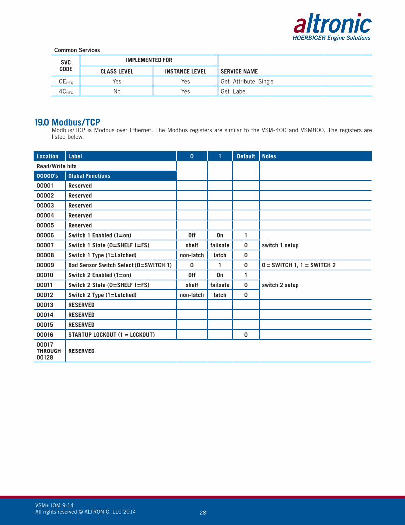
19.0 Modbus/TCP Modbus/TCP is Modbus over Ethernet. The Modbus registers are similar to the VSM-400 and VSM800. The registers are
listed below.
Location Label 0 1 Default Notes
Read/Write bits
00000’s Global Functions
00001 Reserved
00002 Reserved
00003 Reserved
00004 Reserved
00005 Reserved
00006 Switch 1 Enabled (1=on) Off On 1
switch 1 setup00007 Switch 1 State (0=SHELF 1=FS) shelf failsafe 0
00008 Switch 1 Type (1=Latched) non-latch latch 0
00009 Bad Sensor Switch Select (0=SWITCH 1) 0 1 0 0 = SWITCH 1, 1 = SWITCH 2
00010 Switch 2 Enabled (1=on) Off On 1
switch 2 setup00011 Switch 2 State (0=SHELF 1=FS) shelf failsafe 0
00012 Switch 2 Type (1=Latched) non-latch latch 0
00013 RESERVED
00014 RESERVED
00015 RESERVED
00016 STARTUP LOCKOUT (1 = LOCKOUT) 0
00017THROUGH00128
RESERVED
Common Services
SVCCODE
IMPLEMENTED FOR
SERVICE NAMECLASS LEVEL INSTANCE LEVEL
0EHEX Yes Yes Get_Attribute_Single
4CHEX No Yes Get_Label

VSM+ IOM 9-14 All rights reserved © ALTRONIC, LLC 2014 29
Loca
tion
Labe
l0
1N
otes
Read
onl
y bi
ts
1000
0’s
Glob
al F
unct
ions
1000
1RE
SERV
ED
1000
2RE
SERV
ED
1000
3Sw
itch
1 A
ctiv
ated
No
Yes
Outp
ut s
wit
ch 1
act
ivat
ed b
y vi
brat
ion
1000
4Sw
itch
2 A
ctiv
ated
No
Yes
Outp
ut s
wit
ch 2
act
ivat
ed b
y vi
brat
ion
1000
5TH
ROU
GH10
008
RESE
RVED
1000
9Fa
ctor
y Ca
libra
te R
/WRe
ad o
nly
Wri
teFa
ctor
y Ca
libra
tion
Read
/Wri
te
1001
0W
atch
dog
No
Yes
1001
1Sy
stem
Res
ettin
gN
oYe
sRe
set c
ondi
tion
is a
ctiv
e
1001
2RE
SERV
ED
1001
3St
artu
p Lo
cked
Out
Ext
erna
llyou
tput
s ac
tive
outp
uts
inac
tive
Star
tup
term
inal
is a
ctiv
e
1001
4Al
arm
/Shu
tdow
n Pr
esen
t no
ala
rms
alar
ms
Alar
m/S
hutd
own
is p
rese
nt
1001
5RE
SERV
ED
1001
6RE
SERV
ED
Inpu
t #In
divi
dual
Fun
ctio
ns
1001
71
Sens
or S
tatu
sOK
Bad
Sens
orSe
nsor
is d
etec
ted
and
oper
atin
g pr
oper
ly o
r is
not
det
ecte
d
1001
82
Sens
or S
tatu
sOK
Bad
Sens
orSe
nsor
is d
etec
ted
and
oper
atin
g pr
oper
ly o
r is
not
det
ecte
d
1001
93
Sens
or S
tatu
sOK
Bad
Sens
orSe
nsor
is d
etec
ted
and
oper
atin
g pr
oper
ly o
r is
not
det
ecte
d
1002
04
Sens
or S
tatu
sOK
Bad
Sens
orSe
nsor
is d
etec
ted
and
oper
atin
g pr
oper
ly o
r is
not
det
ecte
d
1002
15
Sens
or S
tatu
sOK
Bad
Sens
orSe
nsor
is d
etec
ted
and
oper
atin
g pr
oper
ly o
r is
not
det
ecte
d
1002
26
Sens
or S
tatu
sOK
Bad
Sens
orSe
nsor
is d
etec
ted
and
oper
atin
g pr
oper
ly o
r is
not
det
ecte
d
1002
37
Sens
or S
tatu
sOK
Bad
Sens
orSe
nsor
is d
etec
ted
and
oper
atin
g pr
oper
ly o
r is
not
det
ecte
d
1002
48
Sens
or S
tatu
sOK
Bad
Sens
orSe
nsor
is d
etec
ted
and
oper
atin
g pr
oper
ly o
r is
not
det
ecte
d
1002
5TH
ROU
GH10
032
RESE
RVED
1003
31
SW 2
(SH
UTD
OWN
) SE
TPOI
NT
OKvi
brat
ion
dete
cted
SHU
TDOW
N S
ETPO
INT
Exce
eded
on
Inpu
t 1
1003
42
SW 2
(SH
UTD
OWN
) SE
TPOI
NT
OKvi
brat
ion
dete
cted
SHU
TDOW
N S
ETPO
INT
Exce
eded
on
Inpu
t 2
1003
53
SW 2
(SH
UTD
OWN
) SE
TPOI
NT
OKvi
brat
ion
dete
cted
SHU
TDOW
N S
ETPO
INT
Exce
eded
on
Inpu
t 3

VSM+ IOM 9-14 All rights reserved © ALTRONIC, LLC 2014 30
Loca
tion
Inpu
t #In
divi
dual
Fun
ctio
ns0
1N
otes
1003
64
SW 2
(SH
UTD
OWN
) SE
TPOI
NT
OKvi
brat
ion
dete
cted
SHU
TDOW
N S
ETPO
INT
Exce
eded
on
Inpu
t 4
1003
75
SW 2
(SH
UTD
OWN
) SE
TPOI
NT
OKvi
brat
ion
dete
cted
SHU
TDOW
N S
ETPO
INT
Exce
eded
on
Inpu
t 5
1003
86
SW 2
(SH
UTD
OWN
) SE
TPOI
NT
OKvi
brat
ion
dete
cted
SHU
TDOW
N S
ETPO
INT
Exce
eded
on
Inpu
t 6
1003
97
SW 2
(SH
UTD
OWN
) SE
TPOI
NT
OKvi
brat
ion
dete
cted
SHU
TDOW
N S
ETPO
INT
Exce
eded
on
Inpu
t 7
100
408
SW 2
(SH
UTD
OWN
) SE
TPOI
NT
OKvi
brat
ion
dete
cted
SHU
TDOW
N S
ETPO
INT
Exce
eded
on
Inpu
t 8
100
41TH
ROU
GH10
048
RESE
RVED
100
491
SW1
(ALA
RM)
SETP
OIN
TOK
vibr
atio
n de
tect
edAL
ARM
SET
POIN
T Ex
ceed
ed o
n In
put 1
1005
02
SW1
(ALA
RM)
SETP
OIN
TOK
vibr
atio
n de
tect
edAL
ARM
SET
POIN
T Ex
ceed
ed o
n In
put 2
1005
13
SW1
(ALA
RM)
SETP
OIN
TOK
vibr
atio
n de
tect
edAL
ARM
SET
POIN
T Ex
ceed
ed o
n In
put 3
1005
24
SW1
(ALA
RM)
SETP
OIN
TOK
vibr
atio
n de
tect
edAL
ARM
SET
POIN
T Ex
ceed
ed o
n In
put 4
1005
35
SW1
(ALA
RM)
SETP
OIN
TOK
vibr
atio
n de
tect
edAL
ARM
SET
POIN
T Ex
ceed
ed o
n In
put 5
1005
46
SW1
(ALA
RM)
SETP
OIN
TOK
vibr
atio
n de
tect
edAL
ARM
SET
POIN
T Ex
ceed
ed o
n In
put 6
1005
57
SW1
(ALA
RM)
SETP
OIN
TOK
vibr
atio
n de
tect
edAL
ARM
SET
POIN
T Ex
ceed
ed o
n In
put 7
1005
68
SW1
(ALA
RM)
SETP
OIN
TOK
vibr
atio
n de
tect
edAL
ARM
SET
POIN
T Ex
ceed
ed o
n In
put 8
1005
7TH
ROU
GH10
064
RESE
RVED
1006
51
Chan
nel 1
Arm
ed S
tatu
s N
ot A
rmed
Arm
ed
1006
62
Chan
nel 2
Arm
ed S
tatu
s N
ot A
rmed
Arm
ed
1006
73
Chan
nel 3
Arm
ed S
tatu
s N
ot A
rmed
Arm
ed
1006
84
Chan
nel 4
Arm
ed S
tatu
s N
ot A
rmed
Arm
ed
1006
95
Chan
nel 5
Arm
ed S
tatu
s N
ot A
rmed
Arm
ed
1007
06
Chan
nel 6
Arm
ed S
tatu
s N
ot A
rmed
Arm
ed
1007
17
Chan
nel 7
Arm
ed S
tatu
s N
ot A
rmed
Arm
ed
1007
28
Chan
nel 8
Arm
ed S
tatu
s N
ot A
rmed
Arm
ed
1007
3TH
ROU
GH10
128
RESE
RVED

VSM+ IOM 9-14 All rights reserved © ALTRONIC, LLC 2014 31
Location Label Size(bits) Notes
Read only bytes
30000’s Global Functions
30001 InStat 001-016 MISC.
30002 InStat 017-032 BAD SENSOR Status
30003 InStat 033-048 SHUTDOWN SETPOINT Status
30004 InStat 049-064 ALARM SETPOINT Status
30005 InStat 065-080 ARMED Status
30006 InStat 081-096
30007 InStat 097-112
30008 InStat 113-128
30009 RESERVED
30010 Supply Voltage (1234 = 12.34V) 16 Voltage measured at supply terminals
30011 RESERVED
30012 RESERVED
30013 RESERVED
30014 FACTORY
Input # Individual Functions Min Max
30015 Ch 1 Vibration Level 0 1023
30016 Ch 2 Vibration Level 0 1023
30017 Ch 3 Vibration Level 0 1023
30018 Ch 4 Vibration Level 0 1023
30019 Ch 5 Vibration Level 0 1023
30020 Ch 6 Vibration Level 0 1023
30021 Ch 7 Vibration Level 0 1023
30022 Ch 8 Vibration Level 0 1023
30023THROUGH30029
RESERVED

VSM+ IOM 9-14 All rights reserved © ALTRONIC, LLC 2014 32
Location Label
30030 Event Log 00 (MOST CURRENT/NEWEST)
30031 Event Log 01
30032 Event Log 02
30033 Event Log 03
30034 Event Log 04
30035 Event Log 05
30036 Event Log 06
30037 Event Log 07
30038 Event Log 08
30039 Event Log 09
30040 Event Log 10
30041 Event Log 11
30042 Event Log 12
30043 Event Log 13
30044 Event Log 14
30045 Event Log 15
30046 Event Log 16
30047 Event Log 17
30048 Event Log 18
30049 Event Log 19
30050 Event Log 20
30051 Event Log 21
30052 Event Log 22
30053 Event Log 23
30054 Event Log 24
30055 Event Log 25
30056 Event Log 26
30057 Event Log 27
30058 Event Log 28
30059 Event Log 29
30060 Event Log 30
30061 Event Log 31 (Maximum) (LEAST CURRENT/OLDEST)
30062THROUGH30128
RESERVED

VSM+ IOM 9-14 All rights reserved © ALTRONIC, LLC 2014 33
Location Label Min Max Default Notes
Read/Write bytes
40000’s Global Functions
40001 Coils 001-016 00000 65535 MISC.
40002 Coils 017-032 00000 65535
40003 Coils 033-048 00000 65535
40004 Coils 049-064 00000 65535
40005 Coils 065-080 00000 65535
40006 Coils 081-096 00000 65535
40007 Coils 097-112 00000 65535
40008 Coils 113-128 00000 65535
40009through40012
RESERVED
40013 Lag Filter Gain Value (1-255) 1 255 240
40014 Number of Channels (1-8) 1 8 8
40015 FACTORY 1 65535 10
40016 Switch Hysteresis Time (0-15) 0 15 5
40017 FACTORY 00000 65535 20000
40018 Offset Ch’s 1–4 0 +500 0 Factory Calibration
40019 Offset Ch’s 5–8 0 +500 0 Factory Calibration
40020 Dynamic Filter Step Size 0 1024 50 Factory Set
40021 Dynamic Filter Gain Delay 0 255 15 Factory Set
40022THROUGH40039
RESERVED
40040 Ch#1 Prescale (0-8) 0 8 0
40041 Ch#1 Gain (0-63) 0 63 14 SEE GAIN CHART
40042 Ch#1 BP filter freq (0-63) 0 63 63 Factory Set
40043 Ch#1 time const (0-31) 0 31 31 Factory Set
40044 Ch#1 (ALARM) Setpoint (0-999) 0 999 700
40045 Ch#1 (SD) Setpoint (0-999) 0 999 800
40046 Ch#1 Bad Sens. Setpoint (0-999) 0 999 0
40047 Ch#1 Output Offset 0 500 0
40048 Ch#1 Output Scalar (1234=12.34) 0 9999 100
40049 Ch#1 Label Type (0-48) 0 48 0
40050 Ch#1 Custom Label chars 1 2 00000 65535 22616
ASCII CHAR 1 LOW, CHAR 2 HIGH, IN DECIMAL
40051 Ch#1 Custom Label chars 3 4 00000 65535 22616
40052 Ch#1 Custom Label chars 5 6 00000 65535 22616
40053 Ch#1 Custom Label chars 7 8 00000 65535 22616
40054 Ch#1 Custom Label chars 9 10 00000 65535 22616
40055 Ch#1 Custom Label chars 11 12 00000 65535 22616
40056 Ch#1 Start Delay Timer (0-999) 0 999 60
40057 Ch#1 Trip Delay Timer (0-15) 0 15 3 SECONDS
40058 Ch#1 RESERVED 00000 65535 00000
40059 Ch#1 RESERVED 00000 65535 00000

VSM+ IOM 9-14 All rights reserved © ALTRONIC, LLC 2014 34
Location Label Min Max Default Notes
40060 Ch#2 Prescale (0-8) 0 8 0
40061 Ch#2 Gain (0-63) 0 63 14 SEE GAIN CHART
40062 Ch#2 BP filter freq(0-63) 0 63 63 Factory Set
40063 Ch#2 time const (0-31) 0 31 31 Factory Set
40064 Ch#2 (ALARM) Setpoint (0-999) 0 999 700
40065 Ch#2 (SD) Setpoint (0-999) 0 999 800
40066 Ch#2 Bad Sens. Setpoint (0-999) 0 999 0
40067 Ch#2 Output Offset 0 500 0
40068 Ch#2 Output Scalar (1234=12.34) 0 9999 100
40069 Ch#2 Label Type (0-48) 0 48 0
40070 Ch#2 Custom Label chars 1 2 00000 65535 22616
ASCII CHAR 1 LOW, CHAR 2 HIGH, IN DECIMAL
40071 Ch#2 Custom Label chars 3 4 00000 65535 22616
40072 Ch#2 Custom Label chars 5 6 00000 65535 22616
40073 Ch#2 Custom Label chars 7 8 00000 65535 22616
40074 Ch#2 Custom Label chars 9 10 00000 65535 22616
40075 Ch#2 Custom Label chars 11 12 00000 65535 22616
40076 Ch#2 Start Delay Timer (0-999) 0 999 60
40077 Ch#2 Trip Delay Timer (0-15) 0 15 3
40078 Ch#2 RESERVED 00000 65535 00000
40079 Ch#2 RESERVED 00000 65535 00000
40080 Ch#3 Prescale (0-8) 0 8 0
40081 Ch#3 Gain (0-63) 0 63 14 SEE GAIN CHART
40082 Ch#3 BP filter freq (0-63) 0 63 63 Factory Set
40083 Ch#3 time const (0-31) 0 31 31 Factory Set
40084 Ch#3 (ALARM) Setpoint (0-999) 0 999 700
40085 Ch#3 (SD) Setpoint (0-999) 0 999 800
40086 Ch#3 Bad Sens. Setpoint (0-999) 0 999 0
40087 Ch#3 Output Offset 0 500 0
40088 Ch#3 Output Scalar (1234=12.34) 0 9999 100
40089 Ch#3 Label Type (0-48) 0 48 0
40090 Ch#3 Custom Label chars 1 2 00000 65535 22616
ASCII CHAR 1 LOW, CHAR 2 HIGH, IN DECIMAL
40091 Ch#3 Custom Label chars 3 4 00000 65535 22616
40092 Ch#3 Custom Label chars 5 6 00000 65535 22616
40093 Ch#3 Custom Label chars 7 8 00000 65535 22616
40094 Ch#3 Custom Label chars 9 10 00000 65535 22616
40095 Ch#3 Custom Label chars 11 12 00000 65535 22616
40096 Ch#3 Start Delay Timer (0-999) 0 999 60
40097 Ch#3 Trip Delay Timer (0-15) 0 15 3
40098 Ch#3 RESERVED 00000 65535 00000
40099 Ch#3 RESERVED 00000 65535 00000
40100 Ch#4 Prescale (0-8) 0 8 0
40101 Ch#4 Gain (0-63) 0 63 14 SEE GAIN CHART
40102 Ch#4 BP filter freq (0-63) 0 63 63 Factory Set

VSM+ IOM 9-14 All rights reserved © ALTRONIC, LLC 2014 35
Location Label Min Max Default Notes
40103 Ch#4 time const (0-31) 0 31 31 Factory Set
40104 Ch#4 (ALARM) Setpoint (0-999) 0 999 700
40105 Ch#4 (SD) Setpoint (0-999) 0 999 800
40106 Ch#4 Bad Sens. Setpoint (0-999) 0 999 0
40107 Ch#4 Output Offset 0 500 0
40108 Ch#4 Output Scalar (1234=12.34) 0 9999 100
40109 Ch#4 Label Type (0-48) 0 48 0
40110 Ch#4 Custom Label chars 1 2 00000 65535 22616
ASCII CHAR 1 LOW, CHAR 2 HIGH, IN DECIMAL
40111 Ch#4 Custom Label chars 3 4 00000 65535 22616
40112 Ch#4 Custom Label chars 5 6 00000 65535 22616
40113 Ch#4 Custom Label chars 7 8 00000 65535 22616
40114 Ch#4 Custom Label chars 9 10 00000 65535 22616
40115 Ch#4 Custom Label chars 11 12 00000 65535 22616
40116 Ch#4 Start Delay Timer (0-999) 0 999 60
40117 Ch#4 Trip Delay Timer (0-15) 0 15 3
40118 Ch#4 RESERVED 00000 65535 00000
40119 Ch#4 RESERVED 00000 65535 00000
40120 Ch#5 Prescale (0-8) 0 8 0
40121 Ch#5 Gain (0-63) 0 63 14 SEE GAIN CHART
40122 Ch#5 BP filter freq (0-63) 0 63 63 Factory Set
40123 Ch#5 time const (0-31) 0 31 31 Factory Set
40124 Ch#5 (ALARM) Setpoint (0-999) 0 999 700
40125 Ch#5 (SD) Setpoint (0-999) 0 999 800
40126 Ch#5 Bad Sens. Setpoint (0-999) 0 999 0
40127 Ch#5 Output Offset 0 500 0
40128 Ch#5 Output Scalar (1234=12.34) 0 9999 100
40129 Ch#5 Label Type (0-48) 0 48 0
40130 Ch#5 Custom Label chars 1 2 00000 65535 22616
ASCII CHAR 1 LOW, CHAR 2 HIGH, IN DECIMAL
40131 Ch#5 Custom Label chars 3 4 00000 65535 22616
40132 Ch#5 Custom Label chars 5 6 00000 65535 22616
40133 Ch#5 Custom Label chars 7 8 00000 65535 22616
40134 Ch#5 Custom Label chars 9 10 00000 65535 22616
40135 Ch#5 Custom Label chars 11 12 00000 65535 22616
40136 Ch#5 Start Delay Timer (0-999) 0 999 60
40137 Ch#5 Trip Delay Timer (0-15) 0 15 3
40138 Ch#5 RESERVED 00000 65535 00000
40139 Ch#5 RESERVED 00000 65535 00000
40140 Ch#6 Prescale (0-8) 0 8 0
40141 Ch#6 Gain (0-63) 0 63 14 SEE GAIN CHART
40142 Ch#6 BP filter freq (0-63) 0 63 63 Factory Set
40143 Ch#6 time const (0-31) 0 31 31 Factory Set
40144 Ch#6 (ALARM) Setpoint (0-999) 0 999 700
40145 Ch#6 (SD) Setpoint (0-999) 0 999 800

VSM+ IOM 9-14 All rights reserved © ALTRONIC, LLC 2014 36
Location Label Min Max Default Notes
40146 Ch#6 Bad Sens. Setpoint (0-999) 0 999 0
40147 Ch#6 Output Offset 0 500 0
40148 Ch#6 Output Scalar (1234=12.34) 0 9999 100
40149 Ch#6 Label Type (0-48) 0 48 0
40150 Ch#6 Custom Label chars 1 2 00000 65535 22616
ASCII CHAR 1 LOW, CHAR 2 HIGH, IN DECIMAL
40151 Ch#6 Custom Label chars 3 4 00000 65535 22616
40152 Ch#6 Custom Label chars 5 6 00000 65535 22616
40153 Ch#6 Custom Label chars 7 8 00000 65535 22616
40154 Ch#6 Custom Label chars 9 10 00000 65535 22616
40155 Ch#6 Custom Label chars 11 12 00000 65535 22616
40156 Ch#6 Start Delay Timer (0-999) 0 999 60
40157 Ch#6 Trip Delay Timer (0-15) 0 15 3
40158 Ch#6 RESERVED 00000 65535 00000
40159 Ch#6 RESERVED 00000 65535 00000
40160 Ch#7 Prescale (0-8) 0 8 0
40161 Ch#7 Gain (0-63) 0 63 14 SEE GAIN CHART
40162 Ch#7 BP filter freq (0-63) 0 63 63 Factory Set
40163 Ch#7 time const (0-31) 0 31 31 Factory Set
40164 Ch#7 (ALARM) Setpoint (0-999) 0 999 700
40165 Ch#7 (SD) Setpoint (0-999) 0 999 800
40166 Ch#7 Bad Sens. Setpoint (0-999) 0 999 0
40167 Ch#7 Output Offset 0 500 0
40168 Ch#7 Output Scalar (1234=12.34) 0 9999 100
40169 Ch#7 Label Type (0-48) 0 48 0
40170 Ch#7 Custom Label chars 1 2 00000 65535 22616
ASCII CHAR 1 LOW, CHAR 2 HIGH, IN DECIMAL
40171 Ch#7 Custom Label chars 3 4 00000 65535 22616
40172 Ch#7 Custom Label chars 5 6 00000 65535 22616
40173 Ch#7 Custom Label chars 7 8 00000 65535 22616
40174 Ch#7 Custom Label chars 9 10 00000 65535 22616
40175 Ch#7 Custom Label chars 11 12 00000 65535 22616
40176 Ch#7 Start Delay Timer (0-999) 0 999 60
40177 Ch#7 Trip Delay Timer (0-15) 0 15 3
40178 Ch#7 RESERVED 00000 65535 00000
40179 Ch#7 RESERVED 00000 65535 00000
40180 Ch#8 Prescale (0-8) 0 8 0
40181 Ch#8 Gain (0-63) 0 63 14 SEE GAIN CHART
40182 Ch#8 BP filter freq (0-63) 0 63 63 Factory Set
40183 Ch#8 time const (0-31) 0 31 31 Factory Set
40184 Ch#8 (ALARM) Setpoint (0-999) 0 999 700
40185 Ch#8 (SD) Setpoint (0-999) 0 999 800
40186 Ch#8 Bad Sens. Setpoint (0-999) 0 999 0
40187 Ch#8 Output Offset 0 500 0

VSM+ IOM 9-14 All rights reserved © ALTRONIC, LLC 2014 37
Location Label Min Max Default Notes
40188 Ch#8 Output Scalar (1234=12.34) 0 9999 100
40189 Ch#8 Label Type (0-48) 0 48 0
40190 Ch#8 Custom Label chars 1 2 00000 65535 22616
ASCII CHAR 1 LOW, CHAR 2 HIGH, IN DECIMAL
40191 Ch#8 Custom Label chars 3 4 00000 65535 22616
40192 Ch#8 Custom Label chars 5 6 00000 65535 22616
40193 Ch#8 Custom Label chars 7 8 00000 65535 22616
40194 Ch#8 Custom Label chars 9 10 00000 65535 22616
40195 Ch#8 Custom Label chars 11 12 00000 65535 22616
40196 Ch#8 Start Delay Timer (0-999) 0 999 60
40197 Ch#8 Trip Delay Timer (0-15) 0 15 3
40198 Ch#8 RESERVED 00000 65535 00000
40199 Ch#8 RESERVED 00000 65535 00000
40200THROUGH40256
RESERVED 00000 65535 00000
Register Value
Gain Register Value
Gain Register Value
Gain
0 2.000 23 0.654 46 0.236
1 1.882 24 0.630 47 0.222
2 1.778 25 0.607 48 0.211
3 1.684 26 0.586 49 0.200
4 1.600 27 0.567 50 0.190
5 1.523 28 0.548 51 0.182
6 1.455 29 0.500 52 0.174
7 1.391 30 0.471 53 0.167
8 1.333 31 0.444 54 0.160
9 1.280 32 0.421 55 0.154
10 1.231 33 0.400 56 0.148
11 1.185 34 0.381 57 0.143
12 1.143 35 0.364 58 0.138
13 1.063 36 0.348 59 0.133
14 1.000 37 0.333 60 0.129
15 0.944 38 0.320 61 0.125
16 0.895 39 0.308 62 0.118
17 0.850 40 0.296 63 0.111
18 0.810 41 0.286
19 0.773 42 0.276
20 0.739 43 0.267
21 0.708 44 0.258
22 0.680 45 0.250
GAIN CHART

VSM+ IOM 9-14 All rights reserved © ALTRONIC, LLC 2014 38
FIGURES SECTION:
1. MOUNTING DIMENSIONS AND SPECIFICATIONS
2. MOUNTING, DIMENSIONS, AND SPECS – VIBRATION SENSORS
3A. TYPICAL SENSOR MOUNTING LOCATIONS
3B. TYPICAL SENSOR MOUNTING LOCATIONS
4. WIRING DIAGRAM – SENSOR INPUTS
5. WIRING DIAGRAM – ETHERNET SWITCH
6. WIRING DIAGRAM – HAZARDOUS LOCATIONS
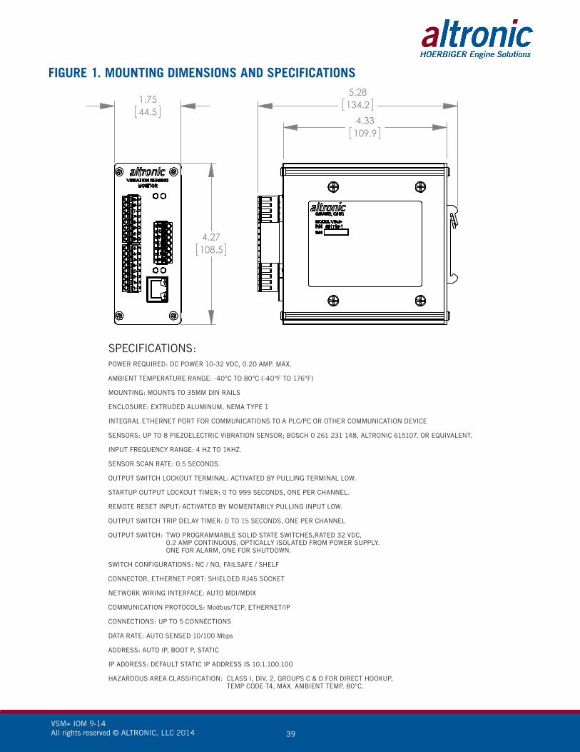
VSM+ IOM 9-14 All rights reserved © ALTRONIC, LLC 2014 39
FIGURE 1. MOUNTING DIMENSIONS AND SPECIFICATIONS
SPECIFICATIONS:POWER REQUIRED: DC POWER 10-32 VDC, 0.20 AMP. MAX.
AMBIENT TEMPERATURE RANGE: -40°C TO 80°C (-40°F TO 176°F)
MOUNTING: MOUNTS TO 35MM DIN RAILS
ENCLOSURE: EXTRUDED ALUMINUM, NEMA TYPE 1
INTEGRAL ETHERNET PORT FOR COMMUNICATIONS TO A PLC/PC OR OTHER COMMUNICATION DEVICE
SENSORS: UP TO 8 PIEZOELECTRIC VIBRATION SENSOR; BOSCH 0 261 231 148, ALTRONIC 615107, OR EQUIVALENT.
INPUT FREQUENCY RANGE: 4 HZ TO 1KHZ.
SENSOR SCAN RATE: 0.5 SECONDS.
OUTPUT SWITCH LOCKOUT TERMINAL: ACTIVATED BY PULLING TERMINAL LOW.
STARTUP OUTPUT LOCKOUT TIMER: 0 TO 999 SECONDS, ONE PER CHANNEL.
REMOTE RESET INPUT: ACTIVATED BY MOMENTARILY PULLING INPUT LOW.
OUTPUT SWITCH TRIP DELAY TIMER: 0 TO 15 SECONDS, ONE PER CHANNEL
OUTPUT SWITCH: TWO PROGRAMMABLE SOLID STATE SWITCHES,RATED 32 VDC, 0.2 AMP CONTINUOUS, OPTICALLY ISOLATED FROM POWER SUPPLY. ONE FOR ALARM, ONE FOR SHUTDOWN.
SWITCH CONFIGURATIONS: NC / NO, FAILSAFE / SHELF
CONNECTOR, ETHERNET PORT: SHIELDED RJ45 SOCKET
NETWORK WIRING INTERFACE: AUTO MDI/MDIX
COMMUNICATION PROTOCOLS: Modbus/TCP, ETHERNET/IP
CONNECTIONS: UP TO 5 CONNECTIONS
DATA RATE: AUTO SENSED 10/100 Mbps
ADDRESS: AUTO IP, BOOT P, STATIC
IP ADDRESS: DEFAULT STATIC IP ADDRESS IS 10.1.100.100
HAZARDOUS AREA CLASSIFICATION: CLASS I, DIV. 2, GROUPS C & D FOR DIRECT HOOKUP, TEMP CODE T4, MAX. AMBIENT TEMP. 80°C.
4.27108.5
1.7544.5
4.33109.9
5.28134.2
SK20564-25-13
MOUNTING DIMENSIONS AND SPECIFICATIONS

VSM+ IOM 9-14 All rights reserved © ALTRONIC, LLC 2014 40
FIGURE 2. MOUNTING, DIMENSIONS, AND SPECS – VIBRATION SENSORS
MOUNT THE VIBRATION SENSORS TO A SMOOTH SURFACE (COUNTERBORE IF NECESSARY) ON THE MACHINE TO BE MONITORED. A SURFACE THAT IS NOT SMOOTH WILL GIVE ERRATIC READINGS. ANGULAR MOUNTING POSITION IS ARBITRARY. DRILL AND TAP THE PART PERPENDICULAR TO THE SURFACE, TAKING CARE NOT TO PENETRATE THE WATERJACKET.

VSM+ IOM 9-14 All rights reserved © ALTRONIC, LLC 2014 41
FIGURE 3A. TYPICAL SENSOR MOUNTING LOCATIONS
ENGINE
COMPRESSOR
NOTES:1. THE VIBRATION SENSOR IS MOST SENSITIVE PARALLEL TO THE MOUNTING BOLT.
2. MOUNT VIBRATION SENSOR ON BOTH SIDES OF ENGINE BLOCK.
VIBRATIONSENSOR
VIBRATIONSENSOR
VIBRATIONSENSOR
VIBRATIONSENSOR
NOTES:1. MOUNT VIBRATION SENSOR ON COMPRESSOR FRAME AND AT EACH HEAD.
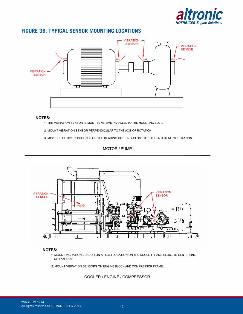
VSM+ IOM 9-14 All rights reserved © ALTRONIC, LLC 2014 42
FIGURE 3B. TYPICAL SENSOR MOUNTING LOCATIONS
MOTOR / PUMP
COOLER / ENGINE / COMPRESSOR
NOTES:1. THE VIBRATION SENSOR IS MOST SENSITIVE PARALLEL TO THE MOUNTING BOLT.
2. MOUNT VIBRATION SENSOR PERPENDICULAR TO THE AXIS OF ROTATION.
3. MOST EFFECTIVE POSITION IS ON THE BEARING HOUSING; CLOSE TO THE CENTERLINE OF ROTATION.
VIBRATIONSENSOR
VIBRATIONSENSOR
VIBRATIONSENSOR
VIBRATIONSENSOR
VIBRATIONSENSOR
NOTES:1. MOUNT VIBRATION SENSOR ON A RIGID LOCATION ON THE COOLER FRAME CLOSE TO CENTERLINE
OF FAN SHAFT.
2. MOUNT VIBRATION SENSORS ON ENGINE BLOCK AND COMPRESSOR FRAME.

VSM+ IOM 9-14 All rights reserved © ALTRONIC, LLC 2014 43
FIGURE 4. WIRING DIAGRAM – SENSOR INPUTS
WIRING DIAGRAM - SENSOR INPUTS
SENOR INPUTSARE DIFFERENTIALDO NOT GROUNDSENSOR (-) 1-
1+
INTERPOSINGTERMINALS
IN PANEL
SK20584-25-13

VSM+ IOM 9-14 All rights reserved © ALTRONIC, LLC 2014 44
FIGURE 5. WIRING DIAGRAM – ETHERNET SWITCH
REMOTERESET
MOMENTARILYGROUND TO RESET
STARTUPLOCKUP
ETHERNETSWITCH
+
_
SWITCH 1
COMMON
SWITCH 2
10-32 VDCPOWER INPUT0.2 AMP. MAX.
GROUND TO DISABLEOUTPUT SWITCHES.OPEN TO ENABLEOUTPUT SWITCHES (PLUSSTARTUP TIMER TIME).
3. OUTPUT SWITCHES ARE RATED 32 VDC, 200 mA MAX. EACH SWITCH TURNS ONTO COMMON WHICH IS ISOLATED FROM DC-.
4. SWITCH 1 IS A CLOSED SWITCH WITH THE ABSENCE OF POWER AND ISTYPICALLY USED FOR AN ALARM OUTPUT.
5. SWITCH 2 IS AN OPEN SWITCH WITH THE ABSENCE OF POWER AND ISTYPICALLY USED FOR A SHUTDOWN OUTPUT.
NOTES:
PLC
CAT-5CABLE
1. POWER WIRING,MUST BE POWERED FROM A CLASS 2 POWER SUPPLY. IT IS RECOMMENDEDTHAT THE CURRENT FROM THE POWER SUPPLY TO THE MODULE BE LIMITED THROUGH A PROPERLY SIZED SURGE TOLERANT FUSE OR ELECTRONIC BREAKER.
2. RJ45 ETHERNET COMMUNICATIONS WIRING,USE DATA GRADE CATEGORY 5E SHIELDED TWISTED-PAIR (STP) OR UNSHIELDEDTWISTED-PAIR (UTP) CABLE THAT HAS A 100Ω CHARACTERISTIC IMPEDANCE THATMEETS THE EIA/TIA CATEGORY FIVE (CAT-5) WIRE SPECIFICATIONS. MAX WIRELENGTH IS 100 METERS / 325 FEET.

VSM+ IOM 9-14 All rights reserved © ALTRONIC, LLC 2014 45
FIGURE 6. WIRING DIAGRAM – HAZARDOUS LOCATIONS