installation of saddle tanks for beechcraft king air … · 2019. 3. 3. · installation of saddle...
TRANSCRIPT

INSTALLATION OF SADDLE TANKS FOR BEECHCRAFT KING AIR
65-A90, 65-A90-1, 65-A90-2, 65-A90-3, 65-A90-4, B90, C90, C90A, C90GT SERIES
AIRPLANES
SUPPLEMENTAL TYPE CERTIFICATE NUMBER SA11142SC
FAA APPROVED AIRPLANE FLIGHT MANUAL SUPPLEMENT
Airplane Serial No:
This supplement must be attached to the appropriate FAA Approved Airplane Flight Manual when the aircraft is modified in accordance with STC SA11142SC. The information contained herein supplements or supersedes the basic Airplane Flight Manual only in those areas listed herein. For limitations, procedures and performance information not contained in this supplement, consult the basic Airplane Flight Manual or Pilot Operating Manual/Handbook for the Beechcraft 65-A90, 65-A90-1, 65-A90-2, 65-A90-3, 65-A90-4, B90, C90, C90A, and C90GT Series airplanes, as applicable.
FAA APPROVED ____________________________ S. Frances Cox, Manager Special Certification Office, ASW-190 Federal Aviation Administration Fort Worth, Texas 76137 Dated: September 11, 2014
DOCUMENT NUMBER AFM 042-1, REVISION 1 CENTEX AEROSPACE INCORPORATED, 7925 KARL MAY DRIVE, WACO, TEXAS 76708
REFERENCE ONLY

REFERENCE ONLY

CENTEX AEROSPACE 042-1 AIRPLANE FLIGHT MANUAL SUPPLEMENT
JULY 2013 Page ii
AIRPLANE FLIGHT MANUAL SUPPLEMENT NO. 042-1 FOR BEECHCRAFT KING AIR 90 SERIES AIRPLANES WITH
CENTEX AEROSPACE SADDLE TANKS CONVERSION
TABLE OF DIVISIONS SECTION 1 ........................................................................................................ GENERAL
SECTION 2 .................................................................................................. LIMITATIONS
SECTION 3 ............................................................................ EMERGENCY PROCEDURES
SECTION 4 .................................................................................. NORMAL PROCEDURES
SECTION 5 .............................................................................................. PERFORMANCE
SECTION 6 ...................................................................................... WEIGHT & BALANCE
SECTION 7 .................................................................................. SYSTEMS DESCRIPTION
SECTION 8 ................................................ HANDLING, SERVICING, AND MAINTENANCE
REFERENCE ONLY

REFERENCE ONLY

CENTEX AEROSPACE 042-1 SECTION 1 AIRPLANE FLIGHT MANUAL SUPPLEMENT GENERAL
JULY 2013 PAGE 1-1
SECTION 1 GENERAL
TABLE OF CONTENTS
SUBJECT PAGE INTRODUCTION ................................................................................................................... 1-2 COMPATIBLE MODIFICATIONS ............................................................................................ 1-2 LIST OF EFFECTIVE PAGES .................................................................................................... 1-3 LOG OF REVISIONS ............................................................................................................... 1-3
REFERENCE ONLY

SECTION 1 CENTEX AEROSPACE 042-1 GENERAL AIRPLANE FLIGHT MANUAL SUPPLEMENT
SEPTEMBER 2014 PAGE 1-2
INTRODUCTION This supplement should be read carefully by the owner and the operator in order to become familiar with the operation of the airplane having now been modified by the installation of the CenTex Aerospace “Saddle Tanks” auxiliary fuel tank system. The new system increases the usable fuel quantity by 180 gallons. The terminology used in this supplement matches the terminology used in the basic Airplane Flight Manual and Pilot’s Operating Manual. This includes the definitions of warnings, cautions, and notes. Also, you will find the format of limitations, procedures, and checklists herein match the Airplane Flight Manual and Pilot Operating Manual/Handbook format for 90 series airplanes. COMPATIBLE MODIFICATIONS The following STC-approved modifications have been found to be compatible with the Saddle Tank installation: 1. SA10747SC, Beechcraft/CenTex Aerospace Halo 90 gross weight increase. 2. SA10935SC, CenTex Aerospace PWC PT6A-21/28/34 Engine Conversion 3. SA822SO, West Tennessee Aviation PWC PT6A-28 Engine Conversion 4. SA10341SC, Blackhawk Modifications PWC PT6A-135A Engine Conversion 5. SA10741SC, Blackhawk Modifications/Silverhawk PWC PT6A-135A Engine Conversion It is up to the installer to determine whether any other STC-approved modifications are compatible with the CenTex Aerospace Saddle Tanks conversion.
REFERENCE ONLY
CENTEX AEROSPACE 042-1 SECTION 1 AIRPLANE FLIGHT MANUAL SUPPLEMENT GENERAL
SEPTEMBER 2014 PAGE 1-3
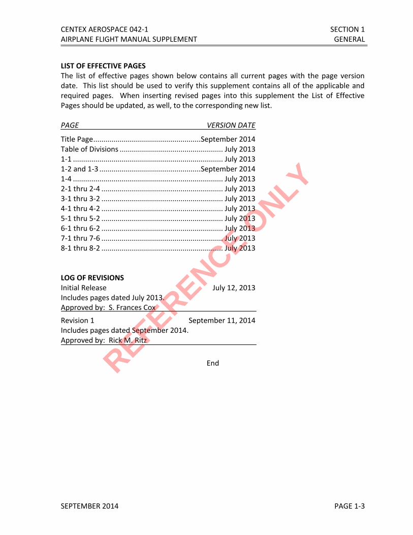
LIST OF EFFECTIVE PAGES The list of effective pages shown below contains all current pages with the page version date. This list should be used to verify this supplement contains all of the applicable and required pages. When inserting revised pages into this supplement the List of Effective Pages should be updated, as well, to the corresponding new list. PAGE VERSION DATE
Title Page ..................................................... September 2014 Table of Divisions ................................................... July 2013 1-1 .......................................................................... July 2013 1-2 and 1-3 .................................................. September 2014 1-4 .......................................................................... July 2013 2-1 thru 2-4 ............................................................ July 2013 3-1 thru 3-2 ............................................................ July 2013 4-1 thru 4-2 ............................................................ July 2013 5-1 thru 5-2 ............................................................ July 2013 6-1 thru 6-2 ............................................................ July 2013 7-1 thru 7-6 ............................................................ July 2013 8-1 thru 8-2 ............................................................ July 2013 LOG OF REVISIONS Initial Release July 12, 2013 Includes pages dated July 2013. Approved by: S. Frances Cox
Revision 1 September 11, 2014 Includes pages dated September 2014. Approved by: Rick M. Ritz
End
REFERENCE ONLY

SECTION 1 CENTEX AEROSPACE 042-1 GENERAL AIRPLANE FLIGHT MANUAL SUPPLEMENT
JULY 2013 PAGE 1-4
THIS PAGE IS INTENTIONALLY BLANK
REFERENCE ONLY

CENTEX AEROSPACE 042-1 SECTION 2 AIRPLANE FLIGHT MANUAL SUPPLEMENT LIMITATIONS
JULY 2013 PAGE 2-1
SECTION 2 LIMITATIONS
TABLE OF CONTENTS
SUBJECT PAGE TEMPERATURE LIMITS ......................................................................................................... 2-2 OTHER LIMITATIONS ........................................................................................................... 2-2 PLACARDS............................................................................................................................. 2-3
REFERENCE ONLY

SECTION 2 CENTEX AEROSPACE 042-1 LIMITATIONS AIRPLANE FLIGHT MANUAL SUPPLEMENT
JULY 2013 PAGE 2-2
INTRODUCTION The limitations shown in this section are approved by the Federal Aviation Administration and must be observed while operating Beechcraft King Air 90 series airplanes that have been modified by the CenTex Aerospace Saddle Tank Conversion STC. This STC approves the installation of a set of auxiliary fuel tanks that have a total capacity of 180 US gallons. TEMPERATURE LIMITS With Saddle Tanks installed, the aircraft shall not be operated when takeoff ambient temperature exceeds ISA + 35°C. This reduction is required to meet the Balked Landing climb requirements. OTHER LIMITATIONS (Airplanes with Saddle Tanks installed)
1. Both left and right wing and nacelle tanks must be full of fuel before fuel can be added to the Saddle Tanks.
2. The maximum allowed fuel imbalance between the Saddle Tanks is 300 pounds (45 gallons).
3. DO NOT TAKEOFF WITH FLAPS EXTENDED when the Saddle Tanks are installed. All takeoff operations must be conducted with the flaps in the UP position. The Takeoff Distance chart shown in the Performance section of the Airplane Flight Manual or Pilot Operating Manual/Handbook does not accurately predict the actual takeoff distance when the Saddle Tanks are installed and the flaps are extended.
4. Balked Landing climb performance depicted in the basic Airplane Flight Manual or Pilot Operating Manual/Handbook must be reduced by applying a penalty of 145 feet per minute to the predicted rate-of-climb when the Saddle Tanks are installed.
NOTE Flight testing has shown when the Saddle Tanks are installed and the flaps are UP the climb performance with two engines operating or with one engine operating is unchanged. See the basic Airplane Flight Manual or Pilot Operating Manual for predicted rate-of-climb.
WARNING Flight testing has shown when the Saddle Tanks are installed and the flaps are extended the actual rate-of-climb will be 145 feet per minute less than the predicted rate-of-climb shown in basic Airplane Flight Manual or Pilot’s Operating Manual. REFERENCE O
NLY

CENTEX AEROSPACE 042-1 SECTION 2 AIRPLANE FLIGHT MANUAL SUPPLEMENT LIMITATIONS
JULY 2013 PAGE 2-3
PLACARDS 1. On top of the Saddle Tank adjacent to the fuel filler cap.
2. On top of the aerodynamic fairing adjacent to the Nacelle Tank fuel filler access door.
3. On inboard rear side of Saddle Tank.
4. On inboard side of main landing gear rear fairing.
End
FUEL DRAIN
FUEL DRAIN
NACELLE TANK FILLER ACCESS
SADDLE TANK FUEL USE JET FUEL
SEE PILOTS OPERATING MANUAL FOR FUEL DESIGNATIONS
CAPACITY 90 U.S. GAL WITH WINGS LEVEL
NACELLE AND WING TANKS MUST BE FULL BEFORE FILLING SADDLE TANKS
REFERENCE ONLY

SECTION 2 CENTEX AEROSPACE 042-1 LIMITATIONS AIRPLANE FLIGHT MANUAL SUPPLEMENT
JULY 2013 PAGE 2-4
THIS PAGE IS INTENTIONALLY BLANK
REFERENCE ONLY

CENTEX AEROSPACE 042-1 SECTION 3 AIRPLANE FLIGHT MANUAL SUPPLEMENT EMERGENCY PROCEDURES
JULY 2013 PAGE 3-1
SECTION 3 EMERGENCY PROCEDURES
NO CHANGES See the basic Beechcraft Airplane Flight Manual or Pilot Operating Manual/Handbook for Emergency Procedures.
REFERENCE ONLY

SECTION 3 CENTEX AEROSPACE 042-1 EMERGENCY PROCEDURES AIRPLANE FLIGHT MANUAL SUPPLEMENT
JULY 2013 PAGE 3-2
THIS PAGE IS INTENTIONALLY BLANK
REFERENCE ONLY

CENTEX AEROSPACE 042-1 SECTION 4 AIRPLANE FLIGHT MANUAL SUPPLEMENT NORMAL PROCEDURES
JULY 2013 PAGE 4-1
SECTION 4 NORMAL PROCEDURES
TABLE OF CONTENTS
SUBJECT PAGE PROCEDURES BY FLIGHT PHASE
PREFLIGHT INSPECTION .......................................................................................... 4-2
BEFORE TAKEOFF ..................................................................................................... 4-2
REFERENCE ONLY

SECTION 4 CENTEX AEROSPACE 042-1 NORMAL PROCEDURES AIRPLANE FLIGHT MANUAL SUPPLEMENT
JULY 2013 PAGE 4-2
PROCEDURES BY FLIGHT PHASE
Steps marked with an * may be omitted except for first flight of the day and after adding fuel to the Saddle Tanks. PREFLIGHT INSPECTION Add the following steps. COCKPIT Landing Gear Handle ......................................................... CHECK DOWN Battery Switch ..................................................................................... ON Saddle Tanks Fuel Quantity Indicators ................ CHECK FUEL QUANTITY Battery Switch .................................................................................... OFF LEFT WING Saddle Tank Filler Cap .................................................................. SECURE * Saddle Tank Sump .......................................................................... DRAIN * Saddle Tank Fuel Line ..................................................................... DRAIN RIGHT WING Saddle Tank Filler Cap .................................................................. SECURE * Saddle Tank Sump .......................................................................... DRAIN * Saddle Tank Fuel Line ..................................................................... DRAIN BEFORE TAKEOFF Add the following step. Flaps ..................................................................................................... UP
WARNING DO NOT TAKEOFF WITH FLAPS EXTENDED when the Saddle Tanks are installed. All takeoff operations must be conducted with the flaps in the UP position. The Takeoff Distance and Single Engine Takeoff Distance (Accelerate Go Distance) charts shown in the basic Airplane Flight Manual or Pilot Operating Manual/Handbook do not accurately predict the takeoff distance when the Saddle Tanks are installed and the flaps are extended.
NOTE Refer to all applicable Supplements for flight phase procedures for optional equipment installed in the airplane. The procedures listed below are required for airplanes modified by the installation of the CenTex Aerospace Saddle Tanks STC.
REFERENCE ONLY

CENTEX AEROSPACE 042-1 SECTION 5 AIRPLANE FLIGHT MANUAL SUPPLEMENT PERFORMANCE
JULY 2013 PAGE 5-1
SECTION 5 PERFORMANCE
SUBJECT PAGE BALKED LANDING CLIMB PERFORMANCE PENALTY ............................................................ 5-2
REFERENCE ONLY

SECTION 5 CENTEX AEROSPACE 042-1 PERFORMANCE AIRPLANE FLIGHT MANUAL SUPPLEMENT
JULY 2013 PAGE 5-2
BALKED LANDING CLIMB PERFORMANCE PENALTY After consulting the Balked Landing Climb chart in the Airplane Flight Manual or Pilot Operating Manual to determine the rate-of-climb for a Balked Landing or Go-Around climb, reduce the predicted rate-of-climb by 145 feet per minute. This penalty was identified and is being applied as a result of flight tests conducted with the Saddle Tanks installed, the landing gear down, and the flaps down. The test results showed the rate-of-climb to be 145 feet per minute less than the rate-of-climb predicted by the Balked Landing Climb chart presented in the basic Airplane Flight Manual or Pilot Operating Manual/Handbook.
END
NOTE Flight testing has shown when the Saddle Tanks are installed and the landing gear and flaps are UP the climb performance with two engines operating or with one engine operating (single engine climb) is unchanged. See the basic Airplane Flight Manual or Pilot Operating Manual/Handbook for predicted rate-of-climb.
REFERENCE ONLY

CENTEX AEROSPACE 042-1 SECTION 6 AIRPLANE FLIGHT MANUAL SUPPLEMENT WEIGHT & BALANCE
JULY 2013 PAGE 6-1
SECTION 6 WEIGHT AND BALANCE
TABLE OF CONTENTS
SUBJECT PAGE SADDLE TANKS WEIGHT AND MOMENT TABLE ................................................................... 6-2
USABLE FUEL ........................................................................................................................ 6-2
UNUSABLE FUEL ................................................................................................................... 6-2
UN-DRAINABLE FUEL............................................................................................................ 6-2
REFERENCE ONLY

SECTION 6 CENTEX AEROSPACE 042-1 WEIGHT & BALANCE AIRPLANE FLIGHT MANUAL SUPPLEMENT
JULY 2013 PAGE 6-2
SADDLE TANKS WEIGHT AND MOMENT TABLE
The table below provides the weight and moment of fuel carried in the Saddle Tanks. Use this weight and moment information when calculating the aircraft weight and balance. Note, weight of fuel in table below is 6.7 lbs per gallon.
Fuel per Tank Gallons
Total Fuel Gallons
Total Weight Pounds
Moment Inch-Lbs (x 100)
5 10 67 144.6
10 20 134 283.0
20 40 268 542.3
30 60 402 800.2
40 80 536 1053.9
50 100 670 1305.9
60 120 804 1555.7
70 140 938 1802.2
80 160 1,072 2045.4
90 180 1,206 2291.4
USABLE FUEL
89.7 Gallons
UNUSABLE FUEL
0.7 Gallons
UN-DRAINABLE FUEL
0.15 Gallons REFERENCE ONLY

CENTEX AEROSPACE 042-1 SECTION 7 AIRPLANE FLIGHT MANUAL SUPPLEMENT SYSTEMS DESCRIPTION
JULY 2013 PAGE 7-1
SECTION 7 SYSTEMS DESCRIPTION
TABLE OF CONTENTS
SUBJECT PAGE SADDLE TANKS FUEL SYSTEM .............................................................................................. 7-2
FUEL QUANTITY INDICATOR SYSTEM................................................................................... 7-5
REFERENCE ONLY

SECTION 7 CENTEX AEROSPACE 042-1 SYSTEMS DESCRIPTION AIRPLANE FLIGHT MANUAL SUPPLEMENT
JULY 2013 PAGE 7-2
SADDLE TANKS FUEL SYSTEM The CenTex Aerospace auxiliary fuel tanks or “Saddle Tanks” add 180 gallons (90 gallons each) of usable fuel capacity to the airplane fuel system. These tanks ride on top of the wing behind the nacelle. The contour of the tank’s lower surface matches that of the wing and fits like a saddle. Three attachment points on the wing hold each tank in place. An aerodynamic fairing streamlines the region between the rear of the engine nacelle and tank. The tanks are constructed solely from aluminum and are an assembly of a formed shell, segmented floor panels, and internal baffles. The tank shell and floor are 0.080 inch thick 6061-T6 aluminum that makes the tanks very durable and easy to repair, and provides excellent protection against lightning strikes and corrosion. The internal baffles, which are constructed from 0.050 inch thick 6061-T6 aluminum, control fuel sloshing and provide stiffness. The pieces are joined by a combination of riveted and welded seams. A special sealant (PRC PR1422) is applied internally to seal the seams. Removable panels in the shell and floor provide access to the inside in case a repair is needed. Each tank weighs approximately 80 pounds. A flush mounted filler cap, which is lightning safe, is located on top of the tank. When securing the cap, it should be properly aligned with the adjacent index mark to ensure proper sealing. As with all fuel tank caps, it is a matter of safety to ensure the cap is closed properly and sealed. A hinged access door in the aerodynamic fairing provides a convenient means to access the nacelle tank filler cap. This door is held closed with a spring loaded latch. To gain access to the nacelle filler cap, press downward on the round button and lift upward on the door. To secure the door, press downward on the door near the button until it snaps closed and the latch engages. Figure 7-1 shows the locations of the Saddle Tank filler cap and the nacelle tank cap access door.
FIGURE 7-1 FILLER CAP AND ACCESS DOOR LOCATIONS
REFERENCE ONLY

CENTEX AEROSPACE 042-1 SECTION 7 AIRPLANE FLIGHT MANUAL SUPPLEMENT SYSTEMS DESCRIPTION
JULY 2013 PAGE 7-3
A sump drain with a push-to-open valve is located at the inboard rear corner of each tank. Opening the drain valve allows fuel from the lowest point in the tank to escape, which serves as a means to drain away water or other contaminates. Figure 7-2 shows the location of the tank sump drain valve.
FIGURE 7-2 TANK SUMP DRAIN
Fuel in the Saddle Tank enters the airplane fuel system through a tee added to the interconnect line between the wing tank and the center section wing tank. The Saddle Tank fuel line is constructed of 5/8 inch diameter aluminum tubing that traverses through the rear of the wheel well fairing under the rear spar and into the wheel well. A drain is provided at the lowest point (under the rear spar) so any contaminates that may have collected in the line can be drained away. Figure 7-3 shows the location of the drain valve.
FIGURE 7-3 FUEL LINE DRAIN
REFERENCE ONLY

SECTION 7 CENTEX AEROSPACE 042-1 SYSTEMS DESCRIPTION AIRPLANE FLIGHT MANUAL SUPPLEMENT
JULY 2013 PAGE 7-4
Figure 7-4 is a schematic of the fuel system with the Saddle Tank (Auxiliary Fuel Tank) system depicted in red. Due to the Saddle Tank being on top of the wing, fuel in the Saddle Tank flows downward into in the center section wing tank assisted by gravity alone. Fuel inside the center section wing tank is handled by the existing fuel system, which pumps it into the nacelle tank. Existing check valves prevent fuel from flowing out of the nacelle tank back into the wing tanks and Saddle Tank. Fuel can gravity flow into the nacelle tank from the wing tanks and the Saddle Tank, but the fuel level inside the nacelle tank must be below the ½ level for this to occur.
It is noted that during training or other flight operations where large pitch attitude changes are being made by the pilot, the quantity of fuel in the Saddle Tanks may increase slightly due to flow past the new check valve. This small amount of fuel will return to the center section wing tank once the pitch attitude changes cease.
FIGURE 7-4 FUEL SYSTEM SCHEMATIC
REFERENCE ONLY

CENTEX AEROSPACE 042-1 SECTION 7 AIRPLANE FLIGHT MANUAL SUPPLEMENT SYSTEMS DESCRIPTION
JULY 2013 PAGE 7-5
FUEL QUANTITY INDICATOR SYSTEM The approximate amount of fuel inside the Saddle Tanks is indicated inside the cockpit by a display of LED lights. These indicator lights are contained in an enclosure mounted next to the Fuel System Circuit Breaker panel beneath the left wing fuel quantity gauges. Each LED light is activated by an optical sensor installed in the wall of the tank. When the sensor lens is submersed in fuel it closes an internal switch that powers the light. Figure 7-5 is an illustration of the system.
FIGURE 7-5
SADDLE TANKS FUEL QUANTITY INDICATOR SYSTEM
The system is powered through the FUEL QTY circuit breaker located in the Fuel System Circuit Breaker panel. A ½ amp fuse provides additional protection from electrical faults. The fuse is located in the bottom of the indicator housing and is easily accessible. All of the LED lights are green in color. An illuminated green light indicates the quantity of fuel in the corresponding tank is at least the amount shown on the label next to the light. A non-illuminated light indicates the quantity of fuel inside the tank is less than the amount specified by the label. The empty indicator lights have two colors – green and amber. When fuel is present the light(s) will illuminate green. The color will change to amber when the tank becomes empty. The amber illumination also shows that the system is operational when all other lights are not illuminated. A non-illuminated empty light indicates a failure of the indicator system has occurred.
REFERENCE ONLY

SECTION 7 CENTEX AEROSPACE 042-1 SYSTEMS DESCRIPTION AIRPLANE FLIGHT MANUAL SUPPLEMENT
JULY 2013 PAGE 7-6
THIS PAGE IS INTENTIONALLY BLANK
REFERENCE ONLY

CENTEX AEROSPACE 042-1 SECTION 8 AIRPLANE FLIGHT MANUAL SUPPLEMENT HANDLING, SERVICING, & MAINTENANCE
JULY 2013 PAGE 8-1
SECTION 8 HANDLING, SERVICING, & MAINTENANCE
NO CHANGES See the basic Beechcraft Airplane Flight Manual or Pilot’s Operating Manual for Handling, Servicing, and Maintenance procedures and instructions..
REFERENCE ONLY

SECTION 8 CENTEX AEROSPACE 042-1 HANDLING, SERVICING, & MAINTENANCE AIRPLANE FLIGHT MANUAL SUPPLEMENT
JULY 2013 PAGE 8-2
THIS PAGE IS INTENTIONALLY BLANK
REFERENCE ONLY