installation of inline (dripline) drip irrigation chapter 1.jains.com/pdf/maintenance...
TRANSCRIPT
More Crop Per Drop® Water is Life®
INSTALLATION OF INLINE (DRIPLINE) DRIP IRRIGATION Chapter 1.
Important Instructions to Farmers : Before Installation Our Company Engineer or Dealer’s representative will visit
the field in which Drip Irrigation System is to be installed and mark the outline for excavating the trenches for laying the sub-main and main pipelines and the location for filters, as per the design.
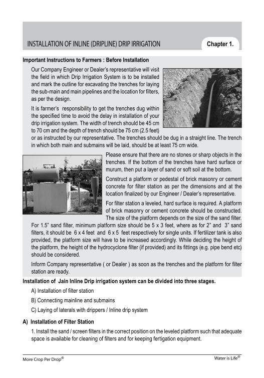
It is farmer’s responsibility to get the trenches dug within the specified time to avoid the delay in installation of your drip irrigation system. The width of trench should be 45 cm to 70 cm and the depth of trench should be 75 cm (2.5 feet) or as instructed by our representative. The trenches should be dug in a straight line. The trench in which both main and submains will be laid, should be at least 75 cm wide.
Please ensure that there are no stones or sharp objects in the trenches. If the bottom of the trenches have hard surface or murum, then put a layer of sand or soft soil at the bottom.Construct a platform or pedestal of brick masonry or cement concrete for filter station as per the dimensions and at the location finalized by our Engineer / Dealer’s representative.For filter station a leveled, hard surface is required. A platform of brick masonry or cement concrete should be constructed. The size of the platform depends on the size of the sand filter.
For 1.5” sand filter, minimum platform size should be 5 x 3 feet, where as for 2” and 3” sand filters, it should be 6 x 4 feet and 6 x 5 feet respectively for single units. If fertilizer tank is also provided, the platform size will have to be increased accordingly. While deciding the height of the platform, the height of the hydrocyclone filter (if provided) and its fittings (e.g. pipe bend etc) should be considered.
Inform Company representative ( or Dealer ) as soon as the trenches and the platform for filter station are ready.
Installation of Jain Inline Drip irrigation system can be divided into three stages. A) Installation of filter station B) Connecting mainline and submains C) Laying of laterals with drippers / Inline drip system
A) Installation of Filter Station 1. Install the sand / screen filters in the correct position on the leveled platform such that adequate
space is available for cleaning of filters and for keeping fertigation equipment.

More Crop Per Drop® Water is Life®
2. Ensure that all the fittings such as pressure gauge, back wash, bypass and air release valves are done properly.
3. Check that the filter candles and mushrooms are fixed in proper position, then fill the sand up to the level marked on the filter.
B) Submain and Mainline Connections 1. Mains and submains are PVC / HDPE pipe lines. PVC pipelines should be laid at a depth of
minimum 2 feet below the ground surface to avoid possible damage to pipelines due to the farm implements used for various cultivation operations in the field.
2. After installation of filter, main pipeline is laid starting from the filter outlet. Air relies valve and Sectional valves (gate valves) are provided on mainline at appropriate locations as shown in the installation sketch. Air release valves are normally installed at points of higher elevation on the mainline and submains.
3. Submains are connected to the mainline using various fittings like Tee, Elbow, etc. as per the installation sketch. Adequate amount of solvent cement should be used to ensure perfect bonding at joints.
4. A flow control valve (ball valve) is provided at the beginning of each submain. A flush valve is provided at the end of each submain to facilitate flushing of submain. The flush valve should be located at about 6 inches above the ground so that the impurities can be flushed out easily. Flush valve should not be fixed in a vertical position. It should be
fixed horizontally after providing an elbow so that water will not be spread on the person while flushing. 5. The parts of the submain control valve (ball valve) and flush valves exposed to direct sunlight should be protected by wrapping a jute bag or cloth. In the sunlight the PVC material becomes hard and brittle and can be broken into pieces.
C) Installation of Lateral Pipes i) Installation of Lateral (Polytube) 1. To connect the laterals (polytube) to the submain, holes
are drilled on the PVC submain pipes using appropriate drill guide and drill. Holes are drilled at a distance equal to the row spacing of the crop as given in the design. The size of hole depends on the size of the lateral and the grommet take off (GTO). For 8mm ID GTO a drill of 11.9 mm diameter is used and for 13 mm ID GTO, 17 mm drill is used.
2. Grommets are fixed in the holes and takeoffs are fixed on the grommets. Laterals are then connected to the take-offs.

More Crop Per Drop® Water is Life®
4. Keep the length of plain polytube till start of bed or first tree. Inline will be connected to this polytube using polyxinline joiner.
ii) Installation of Driplines (Jain Turbo Excel/ Jain Turboline Super/ J-Turboline/ J-Turbo Aqura/ Jain Turboline PC/Jain Turbo Cascade/ Jain Turbo Top)
Proper installation of dripline is important for efficient and trouble free operation. The following recommendations apply to the installation of Jain Turboline.
1. All these driplines may be laid on the surface or buried. 2. Driplines should be laid straight with emitter outlet placed near the root zone. To prevent the
snaking of the lateral, use of ‘C’ clip tube holding stake is recommended. This will ensure application of water exactly in the root zone.
3. Care should be taken during the installation to prevent entry of soil, insects and other contaminants into the tubing.
4 . Proper air release valve shall be installed at the submain to prevent suction in the driplines, when the system is shut down. The suction in the driplines will tend to draw contaminants back into the tubing through the orifices, causing emitter clogging.
5. When applying fertilizers or chemicals through driplines, operate the system till all residual material is flushed out.
Commissioning of Drip Irrigation System After installation, the testing / commissioning should be done in the following way. 1. Ensure that all the control valves and flush valves of submains and lateral ends are open before
testing. 2. Start the pump and allow the water to flow through the system. For a drip system having number
of sections, the water is allowed to flow in different sections one after the other. 3. Check that there is no leakage in the main and submain lines at pipe joints, at connections to
control valves, at various junction points having Tee and Elbow connections and at the lateral take-off points. If any leakage is found, rectify the same. Verify again that there is no leakage of any type in the entire pipeline network and then only the trenches are to be re-filled with the soil.
4. Close the flush valve after the submain is completely flushed.

More Crop Per Drop® Water is Life®
5. When laterals are completely flushed, close their ends with the help of end caps.Close the flush valves.
6. Ensure that pressure gauges on the sand and screen filters are functioning properly. Check the pressure on the gauges installed at the inlet and outlet of the filter. It should be as per the designed pressure at the inlet of filter. During rains water may enter into the gauge and may lead to its rusting. To avoid damage from rains, cover the pressure gauge with Polyethylene sheet or tin can during the rainy season.
7. Allow the water to flow into the system. 8. After the system is completely filled with water read the pressure on the pressure gauge. For
measuring the pressure at the submain, use pressure gauge adopter. 9. Maintain the desired pressure at the filter as mentioned above. If excess pressure is observed,
open the bypass valve slowly till the desired pressure is obtained. 10. At this pressure, measure the discharge of drippers at minimum 25 different places. For this
volumetric method can be used. 11. Check the working of air release valve provided at the inlet of submain. Check the pressure
at the inlet of the submains. It should be about 1.50 kg/cm². 12. After the entire fitting of the system is checked, install ventury (or Fertilizer Tank) on the filter
manifold properly and demonstrate how to apply the chemical treatments and fertilizers through it.
IMPORTANT During the installation and at the time of commissioning of the drip irrigation system our Company’s
/ Dealer’s representative team will explain you the lay-out, different components of the system, their principles, functions and working, and guide you how to operate and carefully maintain the system as well as apply fertilizers and chemical treatment using the Ventury / Fertigation tank. You should understand and learn these things very carefully with full personal involvement as you
have to operate the system independently in future to derive the benefits of this hi-tech method. So get all your doubts clarified from our representative team during the installation.

More Crop Per Drop® Water is Life®
MAINTENANCE OF INLINE DRIP IRRIGATION SYSTEM
There are basically two reasons why maintenance of drip irrigation system is so important. 1) Water is never found in its purest form in nature. Always it contains some physical, chemical
and biological impurities which may block the pipeline, laterals and drippers in the system. 2) The function of dripper / emitter is to allow a gradual transition of water flow from high pressure
(nearly 1.0 kg/cm²) to atmospheric pressure when it comes out through emitter, so as to get discharge in the form of a droplet. In doing so the flow of water has to pass through labyrinth, turbulent and minute flow path. There is always a chance of blockage of this flow path due to dirt particles or due to chemical precipitation.
In order that your drip irrigation system works smoothly and efficiently for years together, it is very essential to maintain the system with great care.
For this you can prepare your own system maintenance schedule. The schedule can be divided into daily, fortnightly, monthly and half-yearly maintenance activities as given below.
A) DAILY MAINTENANCE In order to get maximum efficiency and optimum results it is
necessary to prevent clogging of emitters, sprinklers and laterals. Properly maintained filters will ensure maximum efficiency of irrigation systems, by avoiding clogging. Hence, filtration unit is the heart of irrigation system.
Following activities should be carried out daily. 1) Start the pump and allow the pressure to become stable. Open
the drain valves of hydrocyclone and screen filters to remove the debris.
2) Backwash the sand filter. Backwashing is the process in which flow direction is reversed so that water flows upwards through
the sand bed. The sand gets lifted up and expands allowing it to release the dirt arrested in it. The dirt id then driven out of the filter through the backwash valve. If backwashing is not done regularly, then the impurities accumulate in the sand bed which reduces the efficiency of the filter
and the system does not get water at desired pressure. Backwashing of sand filter should be strictly done in the following sequence.1. Open the Backwash valve.2. Close the Outlet valve.3. Open the Bypass valve.4. Close the Inlet valve.
Bypass ValveInlet Valve
Outlet Valve
Backwash Valve
Chapter 2
More Crop Per Drop® Water is Life®
Backwash operation is complete when clear water starts flowing out through the backwash valve. To resume the filtration process again, 1) Open the Inlet valve, 2) Close the Bypass valve, 3) Open the Outlet valve, and 4) Close the Backwash valve. Clean the filters after every 5-6 hours or at recommended timings based on the water quality analysis report.
2) After cleaning the filters, operate the by-pass valve of the header assembly to obtain the desired pressure in the system. Operating the system at design pressure results in uniform discharge through the drippers as well as reduction in clogging or choking of laterals and drippers.
3) Take a round of the entire field and check if there is leakage at joints or damage to any component of the system. rectify the defects, if any, by replacing the spares. Remove the folds or kinks on the laterals, if found, and make them straight.
4) Check drippers for uniformity of discharge. Open and clean the drippers which are not emitting water. Do not pull the emitter while cleaning, it will enlarge the hole on the lateral causing leakage.
5) After irrigation is over, check whether the wetting patterns of the drippers are uniform or not. Also check the wet bulb depth taking auger holes randomly.
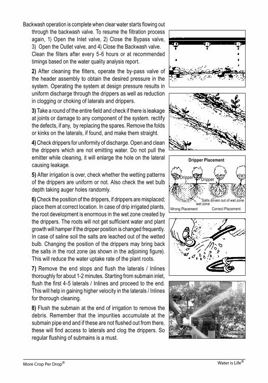
6) Check the position of the drippers, if drippers are misplaced; place them at correct location. In case of drip irrigated plants, the root development is enormous in the wet zone created by the drippers. The roots will not get sufficient water and plant growth will hamper if the dripper position is changed frequently. In case of saline soil the salts are leached out of the wetted bulb. Changing the position of the drippers may bring back the salts in the root zone (as shown in the adjoining figure). This will reduce the water uptake rate of the plant roots.
7) Remove the end stops and flush the laterals / Inlines thoroughly for about 1-2 minutes. Starting from submain inlet, flush the first 4-5 laterals / Inlines and proceed to the end. This will help in gaining higher velocity in the laterals / Inlines for thorough cleaning.
8) Flush the submain at the end of irrigation to remove the debris. Remember that the impurities accumulate at the submain pipe end and if these are not flushed out from there, these will find access to laterals and clog the drippers. So regular flushing of submains is a must.
Dripper Placement
Dripper
Salts driven out of wet zone
Wrong Placement wet zone Correct Placement
Dripper

More Crop Per Drop® Water is Life®
B) FORTNIGHTLY MAINTENANCE After completing the steps 1 to 8 of the Daily Maintenance Schedule given above, perform the
following operations at every 15 days interval. 1) Sand Filter The pressure difference between the inlet and outlet of a filter is an indicator that suggests whether
filters need cleaning. If pressure difference is more than 0.5 Kg/cm² (5 m of water), it means filter needs cleaning. The pressure difference between the inlet and outlet of a filter can be checked using a pressure gauge provided with a 3-way control valve.
Due to deposition of salts present in water the top surface of sand bed becomes hard like a stone and backwashing is not effective to clean the sand bed. Therefore, clean the sand filter every 15 days as follows-
i) Open the lid of sand filter as illustrated in the figure. ii) Allow the water to come out through the lid opening. Adjust the flow using bypass valve such
that sand does not come out of the opening. iii) Stir the sand thoroughly by moving the hand through
entire sand media from top to bottom. Be careful and do not disturb the position of the black filter candles provided at the bottom, else sand may enter the screen filter.
iv) Break the lumps of sand by squeezing in hand. v) Ensure that half the filter is filled with sand up to the level
marked on the filter. Add new sand if it is below the mark. vi) Allow water to flow till clean water starts flowing out of
the opening. vii) Put the lid back in position tightly. The sand used in filter is a special type of crushed silica sand having angular particles. Due to
interlocking of particles the dirt is arrested in this sand, which is not possible in ordinary sand having rounded particles. Therefore, never use ordinary river / nallah sand in the filter.
Before flushing the laterals, remove the end stop of any lateral and wrap a clean white cloth at its open end and allow water to pass through it for some time. Then observe the impurities retained on the cloth. This will help in identifying the problems in the system and to decide the maintenance strategy, e.g. if algae is observed on the cloth, then chlorine treatment can be performed; alternatively a sand filter can be installed, if it was not provided.

More Crop Per Drop® Water is Life®
2) Screen Filter The fine particles and dirt which escape through the sand filter
are arrested on the filtering element of screen filter. This affects the filtering process. Therefore, it is essential to clean the filtering element every 15 days. For this, open the lid of screen filter and take out the filtering element. Remove the rubber seals from both ends of the filtering element ; reverse them, clean with water and fix them tightly on the element again. Rinse the element in flowing water gently with hand, as shown in figure, and clean it. Do not use wired brush, as it may damage the screen.
C) MONTHLY MAINTENANCE If the salts, algae and other impurities present in water enter into the drip irrigation system, then the
laterals and drippers get clogged and may stop emitting water. Therefore, it is necessary to apply acid and chlorine treatments once in a month or as recommended in the water quality analysis report. The procedure and calculation of doses for acid and chlorine treatment are explained in detail in Chapter 6.
1) Perform acid treatment to remove precipitated salt from drippers and pipeline network. 2) Perform chlorine treatment to remove bacterial slime, algae or other biological contamination. 3) Inspect all the component above ground for physical abuse, damage by field machinery, rats,
squirrels etc. Do not perform both acid and chlorine treatment simultaneously.D) HALF YEARLY MAINTENANCE 1) Change the sand of the media filter with new one as sand particles get rounded off due to
continuous abrasion during operation. 2) Check out the system for wear and tear, replace the spares whenever necessary. 3) If the pump works efficiently, it generates the adequate pressure head and discharge required
to operate the system satisfactorily. Provide adequate lubrication to the pump and motor. Make necessary maintenance of the pump as per instructions given by pump manufacturer.
Importance of Operating Drip System at Correct Pressure Always maintain a pressure of 1.5 kg/cm² at the submain. Please note that maintaining proper
pressure is very important as it directly affects the plant performance i.e. its growth and yield. Do not keep the system pressure very high or very low. The higher pressure will result in discharging
more water than required by the plants. This will cause runoff and the soil in the root zone will be fully saturated. Such over-irrigation not only results in wastage of water and nutrients, but also disturbs the air-water balance in the plant root zone. As the plant roots are deprived of oxygen, the root and plant growth will be poor and thus the crop yield will reduce.
If the system pressure is lower than 1 kg/cm², the drippers will supply much less water than the plant’s requirement. The plant will be subjected to water stress. If such condition prevails for a longer period the growth of plant will stop or even the plant may die. Therefore, always run the drip system at proper pressure as mentioned above.

More Crop Per Drop® Water is Life®
GENERAL MAINTENANCE TIPS Have you paid attention to the following important things? 1) Check whether all components of the drip irrigation system are installed properly and are
working efficiently. 2) At least one outlet of the dripline shall be facing upwards.
In case of dripline with strip emitters, there is only one outlet. In case of driplines with cyllindrical emitters, there can be multiple emitters. Outlet facing upright takes in the air and break the partial vaccumm created during shutoff of the system.
3) If the pressure difference between inlet and outlet of the sand filter is more than 0.5 kg/cm², it is the indication that the filter needs backwashing.
4) Open the sectional valves of the section/s to be irrigated as per requirement. Refer to the Technical Information Report supplied with the design.
5) Sometimes farmers use mud or cow dung for priming of pump. The mud or cow dung so used should be thrown out of the system using the bypass valve after the. Otherwise, these will be deposited on the sand bed of the filter forming a hard layer and proper filtration will not take place.
6) Bypass valve arrangement is essential in the system. Provide it, if it is not existing. 7) If the sand and screen filters are cleaned regularly, there will be no reduction in their filtering
capacity and they will continue to work efficiently. 8) Half of the filter is always filled with sand up to the level marked on the filter. Add new sand if it
is below the mark. Never use ordinary river / nallah sand in the filter. Use the special crushed silica sand available for the purpose.
9) Observe the wetting patterns of the drippers of Inline. If the wetting pattern is not uniform, then apply suitable corrective measures like- clean the drippers, flush the laterals / Inlines / submains, provide acid / chlorine treatment.
10) If the drip system is put off for a few days, it is likely that some insects occupy the drippers and laterals. Some insects may even build cocoon inside. This may reduce the flow rate. It is, therefore, wise to operate the system daily for about 10-15 minutes.
11) If lateral is found to be broken for some reasons, cut it and put a poly-joiner and join the ends to stop the leakage.
12) To protect the laterals from squirrels, place bowls full of water in different locations in the field for squirrels. Wrap GI sheet/plastic / polyethylene cloth around the trunks of big trees so that squirrels can not climb the trees.
13) Rats are very destructive creatures. They not only damage the laterals of drip irrigation system, but also destroy the food grains and seeds etc. To protect the system from rats following measures can be adopted.

More Crop Per Drop® Water is Life®
• Always maintain continuous wetted strip in the field. This is very well possible in closely spaced crops. Rats are afraid of water and laterals can be saved by maintaining wetness.
• If the distance between the drippers is more as in case of orchards, bury the lateral line between two drippers about 3 to 4’’ below the ground.
• Use rat repellent chemicals along the laterals. • Start a ‘Rat Campaign’ to destroy the rats. This campaign should be taken up by all the
farmers in the area simultaneously. They should search for bore holes in the farms and close all the holes with mud. Keep some marks for identifying the hole locations. Next day inspect the holes and close down the holes which are found open. Open holes indicate presence of rats. Place rat killing tablets / powder mixed eatables around the holes. If all farmers take up the campaign together, then it is possible to destroy the rats.
• Do not kill the snakes in the field. Snakes control the population of rats.
Special Precautions for Dripline System (Jain Turbo Excel/ Jain Turboline Super/ J-Turboline/ J-Turbo Aqura/ Jain Turboline PC/Jain Turbo Cascade/ Jain Turbo Top) 1) Dripline should be laid straight and exactly in the centre of the two crop rows so that each row
gets uniform quantity of water. If the dripline has any folds or kinks, then the further length of tubing will not get sufficient pressure and the crop will get less water than its requirement.
2) For dripline system a sand filter is essentially required and proper maintenance of sand filter is the key for the best performance of the system.
3) In dripline system an air-cum-vacuum release valve should be installed either at the inlet of the submain or at the point of highest elevation on the submain. It releases the entrapped air when the pump is started and breaks the vacuum during shut off.
4) If the dripper discharge is observed to be low, then hammer the dripper gently with hands to remove salt or dirt deposited inside. Do not use needle, nail or sharp metal objects for cleaning the dripper.
5) Install the dripline tubes in the field in the morning hours or in the evening when it is cool, so that drippers will remain at proper position.
6) At least one outlet of the dripline shall be facing upwards. In case of dripline with strip emitters, there is only one outlet. In case of driplines with cyllindrical emitters, there can be multiple emitters. Outlet facing upright takes in the air and break the partial vaccumm created during shutoff of the system.
6) Before planting vegetable, sugarcane and similar crops, the dripline should be run continuously for 24 - 48 hours to ensure sufficient moisture for germination. This is known as planting / germination irrigation. The duration of this irrigation depends upon
Air-cum-vacuum release valve

More Crop Per Drop® Water is Life®
the season, climate and soil/crop. Prior to irrigation for planting, the land should be prepared properly making the soil friable by breaking the clods.
7) If the dripline is run daily, the rat menace can be considerably reduced. Use of kerosene, neem cake, zinc phosphate tablets are some other measures to control the rat problem.
8) Dripline system should not be kept off for a long duration. It must be operated at least for 2-3 hours in a week, even in rainy season or when not in use, just to flush the tubing. Otherwise the holes may get clogged and also bacterial or algae growth may take place.
9) When the dripline is to be taken out of the field, it should be chemically treated before taking it out. It should be properly wound and stored in a safe place to protect from rats, ants, etc.
10) During harvesting, tractor or bullock cart should not be taken in the field. It may damage the dripline. 11) The labour should be made well aware of the Inline laid in the field and care should be taken to
avoid damage to it during intercultivation operations as well as harvesting the crop, especially sugarcane.
12) As far as possible do not burn the sugarcane trash. It can be used for mulching or for composting. 13) It is always safer to burn the sugarcane trash out of the field. But if burnt in the field, first ensure
that the Inline is completely covered with soil and on the previous day the systems should be run to wet the soil sufficiently.
14) After burning the trash, the Inline should be taken out carefully if ratoon crop is not to be taken. 15) Regular acid treatment is necessary to avoid chemical precipitation and clogging of the system. 16) Ensure proper chlorination to control the algae and bacteria growth in the system.
GUIDE LINE FOR SUB SUBSURFACE DRIP IRRIGATION (SDI) SYSTEM USING ‘JAIN TURBO EXCEL’ AND ‘JAIN TURBOLINE SUPER’ FOR SUGARCANE• Placement of lateral in SDI for Sugarcane:Please follow:
1. Install ‘Jain Turbo Excel/Jain Turboline Super’ 10-15 cm below the surface of the soil.2. Place cane setts at 22 cm below the soil.3. Setts should be below the lateral and 30 cm (minimum) away from the lateral.

More Crop Per Drop® Water is Life®
The logic is:1. Roots tend to grow down and at least in the first year they do not attack the lateral.2. Water moves down (gravity) more than it moves up (capillary) so it reaches the newly planted
sett and initiate germination.3. The depth of 10-15 cm at planting will increase as earthing-up is carried out and altogether
protect the lateral while the harvester operates.• Proper soil preparation is very important. Do not allow any clods in the field.• Flushing head control, main and submains.Flush the head and pipes thoroughly until the tail water is clear. Be sure to flush out all plastics
cuttings, grit, stones etc. It is recommended to flush just before installation of the laterals. Note: Do not leave pipes or connector outlets open for more than a few minutes.• Connecting laterals : Prevent sharp bends to avoid kinks in the laterals. Use polyelbows to avoid
kinking of lateral.• Place the emitter of Jain Turbo Excel facing up while laying it. • Even though longer running length can be achieved using Turboline PC or Turbo Cascade PC
(Amnon PC); It is not necessary all the time go with PC. Similar running length is possible by using higher dia. (20mm and more) inline tubing.
• For larger section select 63mm/50mm size collecting drain sub main to accommodate more space for silt and to minimize the head losses.
• It is recommended to place the collecting sub main at 6” to 8” lower than lateral level. This is to avoid backflow of dirt in to the laterals of ‘Jain Turbo Excel/Jain Turboline Super’.
• Connect ARV/ vacuum breaker valve with each sub-main inlet, near the flush valves, at inlet and flushing end of the collecting drain and at head control unit. Single Union ARV can be used for this purpose.
• NRV is necessary part of the system. Install NRV before head control unit. • It is recommended to install “Spin Clean Filter” which is a combination filter of ‘Jain Sand Separator’
and Screen/disc filter. All debris collected on the periphery of screen/disc element will settle down in the sand separator when pump is put off.
25 95
DRIP LINE7
15
TWO ROWS OF CANE SETT
715
25
ONE DRIP LINE FOR TWO ROWS OF CANEPAIR TO PAIR AT 4' (120 CM)
120
PLACEMENT OF DRIP LATERAL IN SDI
More Crop Per Drop® Water is Life®
• Select proper filtration according to quality of water.• Wherever possible connect Venturi before hydrocyclone/sand separator filter and its outlet is to
be connected after the outlet of the screen/disc filter to minimize the head loss at the venturi point. This reduces the throttling of valve.
• Keep pressure check points at various locations in section to check the pressure.• Clean the flush valve with higher pressure to achieve higher flushing velocity.• While cleaning disc filter, ensure that it has properly cleaned and tightened to avoid escape of
through the discs. • During rainy season the system will allow to run at least minimum 15 to 20 minutes in a day if not,
there may be a chance to form salt deposition at the emitters.• Similarly, the system does not allow idle for more than two days unless the root will enter into
the emitters to absorb water. Keep sufficient moisture level within the root zone to avoid root intrusion.
• After completing installation, check the inline properly connected with elbow, plain lateral, sub main and connection of Inline elbows.
• Before refilling the trenches ascertain any leakages or improper joints incurred, if so it has to correct carefully.
• Ensure that you are getting sufficient wetted zone near roots. Use low cost Augur for this purpose.
CHEMlCAL TREATMENTS:
A.TRIFLORALIN TREATMENT :
• To avoid root intrusion,inject Trifloralin 0.125ml per dripper 3 weeks after 1st irrigation and give 2nd treatment two weeks before harvesting.
• Inject the Trifloralin for short period of 5-10 minutes only. Allow the irrigation after 24 hours of the treatment.
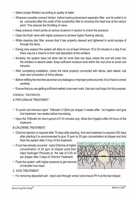
B.CHLORINE TREATMENT:• Chlorine injection is required after 75 days after planting. And next treatment is required 250 days
after planting.It is recommended to give 10 ppm to 20 ppm concentration at dripper end.And flush the system after 2 hour of the treatment.
• If root has already occurred , inject Chlorine at higher concentration of 20 ppm at dripper point.then inject Hydrogen Peroxide at the rate of 0.05 ml per dripper after 2 days of Chlorine Treatment.
• Flush the system with higher pressure to get removal of intruded root mass.
C. ACID TREATMENT:• For removing deposited salt , inject acid through venturi and ensure PH 4 at the last dripper.

More Crop Per Drop® Water is Life®
CHEMICAL TREATMENTS IN DRIP IRRIGATION SYSTEM
Quality of water is the most important factor for the successful functioning of a drip system. Drip system consists of large number of emitters which have very small flow paths. The emitters are prone to blockage or clogging due to the contamination through the source water. The factors responsible for clogging phenomenon include the – 1) presence of microorganisms, 2) the size and quantity of suspended solids in the water, and 3) the presence of certain dissolved solids such as iron, calcium & magnesium, carbonates and bicarbonates which may precipitate and form deposits within the lateral lines and emitters. The clogging of a drip system could be due to the following reasons.
1. Presence of large particles as well as suspended silt and clay load in the source water 2. Growth of bacterial slime in the system 3. Growth of algae in the water source and in the drip system 4. Bacterial precipitation of iron or sulphur 5. Chemical precipitation of dissolved salts (present in source water) in laterals, drip tapes
and drippers Physical treatment like filtration will not remove the dissolved solids/salts, bacteria or microscopic
algae from water. The bacteria and algae can grow in the drip system or can interact with particles of silt and clay and form clusters or can catalyze precipitation of salts. Such precipitation can cause clogging or blockage of laterals and drippers. Therefore, chemical treatment of water either at source or within the system is the most useful method of preventing or rectifying the clogging problem. In chemical treatment acid or chlorine is injected in the drip irrigation system along with irrigation water.
The equipment such as venturi, fertilizer tank and injector pump are used for applying chemicals and fertilizers through Drip Irrigation System.
Acid can be injected by using following equipment, a. Venturi injector: Most commonly used. Check that the
suction capacity of the venturi is sufficient to inject the required quantity of acid/chlorine within given time. If the capacity is low we can divide the sections in parts by closing the inlets of the laterals.
b. Fertilizer Tank: It is a metal pressure vessel. If fertilizer tank is to be used, Fill up the fertilizer tank partially with water leave the required volume of acid/chlorine. cover the tank with plastic sheet. Make a hole at the manhole place. Put the funnel on the manhole and slowly pour the acid/
Filter Inlet valve
Venturi Assembly
Strainer
Chapter 3

More Crop Per Drop® Water is Life®
chlorine solution. Do not spill the acid/chlorine anywhere on the tank surface. Wash the fertilizer tank thoroughly after every treatment from inside and outside.
c. Injector pump: Hydraulically operated injector pump: This is used for smaller areas. Manually operated injector pump: Foot pumps/ back pack pumps can be used. These can be
directly connected to the sections through laterals. Make sure that laterals are tied up carefully and shall not snap off at higher pressures. Pumps used shall be having chemical resistant spares such as washers etc.
CALCULATION FOR TIME OF TREATMENT: We need to calculate time of treatment before we start the treatment because every section size
in the field may be different. It is a one time calculation and need not to be repeated unless system hydraulics is changed. Following are the steps to calculate time of treatment,
1. Start on the pump 2. Set design pressure for the section 3. Throttle the valve of venturi manifold create differential pressure for desired suction rate. 4. Use colour dye as an injection liquid. 4. Start injecting this solution, start on the stopwatch. 5. Measure the time required to reach the coloured solution till the last dripper of the
section. 6. Repeat the similar procedure for other sections. 7. Flush out the solution by opening end caps of the laterals. 8. Note down section no., size, time required, differential pressure etc. for future
treatments. A fair estimate of this time can also be obtained by dividing the total length of main line + submain
+ lateral by the velocity of flow 0.8 m/s (after throttling the valve for injector). If a section of a field has 900 m pipe length (main line + submain + lateral), the time taken to reach the last dripper is 900/0.8 seconds; i.e. 1125 seconds or 18.75 minutes say 20 minutes.
ACID TREATMENT Precipitation of salts such as calcium carbonate, magnesium carbonate or ferric (iron) oxide can
cause either partial or complete blockage of the Drip Systems. Acid treatment is applied to prevent precipitation of such salts in the drip system. Acid is also effective in cleaning systems which are already partially blocked with precipitates of salts. Acid may also be used to lower the pH of the water in conjunction with the use of chlorine injection to improve the effectiveness of the chlorine as a biocide.
The most reliable step for deciding on acid treatment is the water analysis. Soil and water samples are collected during the survey and then analyzed to recommend acid or chlorine treatment as per the water quality.

More Crop Per Drop® Water is Life®
For Acid treatment any one of the following acids can be used.
Hydrochloric Acid HCl - 35 %
Nitric Acid HNO3 - 33%
Sulfuric Acid H2SO4 - 65 %
Ortho Phosphoric Acid H3PO4 - 85%
Normally hydrochloric acid (HCL) is used as it is readily available in the market. HCL can be used when during routine maintenances schedule or when 30-50% of emitters are blocked (partial blockage). HCL shall not be used for crop sensitive for chlorine.
Nitric and ortho phosphoric acids are although weak acids but can be used during regular maintenance as they also provides required nutrients.
If the blockage due to salt precipitation is severe, sulfuric acid can be used. Many times if due maintenance care is not taken for long period, salts which are precipitated gets
cemented up. It is difficult to remove such cemented salts during single acid treatment. In such case repetitive acid treatments required to be followed.
During the intermittent acid treatment, the pH value of water in the system should be 4. The pH value of water is measured using pH paper. For this, dip the pH paper in the water to be
used in drip system. Match the color of pH paper with the one on the color-scale. The pH value of this color on the color-scale is the pH value of the water.
If the pH value of the source water is high (>7, alkaline water), more acid will be required to bring its pH value to 4.
Acid treatment can be applied to a number of irrigation sections (submains) at a time or separately to each submain depending upon the irrigation scheduling and capacity of injector. Accordingly the volume of acid required for the treatment is estimated.
Material and accessories required to access acid quantity 1. A plastic bucket 2. Plastic jar of 10 liter volume. 3. A dropper/injection marked with scale having minimum 1 ml list count. (available in any
medical shop) 4. pH paper that indicates color change according to pH shift 5. Hydrochloric acid (Commercial grade) / any other acid to be used for treatment.

More Crop Per Drop® Water is Life®
Procedure for Acid TreatmentStep 1. Estimation of volume of acid required for treatment 1. From the water source used for drip system, take 10 litre of water in a plastic bucket. Make
sure that bucket is thoroughly cleaned and without any scaling. (If there are more than one water source, take the samples from both the sources and
carry the below given steps separately for each source.) 2. Put the hand gloves and goggle. Keep the pH paper ready. 3. Add acid drop by drop in this 10 litre water using a
dropper/injection. Stir the water well and measure its pH value.
4. Continue the above process till the pH value of water is equal to 4 (i.e. till the color of pH paper changes to light pink). Stop adding acid to water.
5. Note the quantity of acid in ml required to obtain pH value of 4. (Say it is 2 ml)
6. Note the flow rate for the section to be treated from the design. If the system flow rate is not known, then use the value of “Nominal flow rate in m3/hr” written on the filter of the system. (Say the system flow rate is 25m3/hr)
7. Calculate the quantity of acid required for treatment of the given section as given below.
Acid required for 10 liter water for attaining pH value of 4 = 10 ml.
Motive f low in the sect ion just to f i l l the section (total flow in 20 minutes considering time of treatment as 20 min.) = (25,000/60) x 20 = 8333.33 liter
Volume of acid required for acidulating 8333 liter water = (8333 ltr x 10 ml)/10 ltr= 8.33 liter. Thus, approximately 9 litres of acid will be required to treat the section.
Checking pH Value
Acid
Water 1 Litre
pH Paper

More Crop Per Drop® Water is Life®
Step 2. Injection procedure 1. Start on the pump. Set the desired suction rate so as to inject the acid within calculated
time of treatment. 2. Take the acid in the bucket/ fertilizer tank. 3. Check the pH of water at the nearest dripper of the section. If pH is observed to be more
than 4, then increase the suction rate by slightly closing the valve. 4. In this way by throttling the valve allow the acid mixed water having pH value of 4 to reach
up to the last dripper. Close the submain valve or switch off the pump. Keep the system closed for 24 hours. It takes minimum 6 hrs for the salts in the system to dissolve in the acid mixed water.
5. After 24 hours open the submain flush valve and the ends of all laterals. Start the pump and flush out the entire system so that all acid and dissolved the salts are driven out of the system.
When do you need acid injection? • It depends on the salt content in the water denoted by EC reading in a water test report. • For EC above 0.5, acid injection is recommended. • The frequency of acid injection for EC up to 1.0 can be 45 days; for EC 1.0-1.5 it should be
30 days and for above 1.5 to 2.5 it should be 15 days. • For EC above 2.5 do not accept the water for drip irrigation. (Educate the farmer about the
problem with his water). • If fertigation with Water soluble fertilizers is practiced acid injection is not necessary. • If fertigation includes Potash (MOP or SOP) or Ammonium sulphate fertilizer reduce the
frequency of acid injection. • If Urea alone is applied normal acid injection should be carried out.Trouble shooting while injecting acid. • No injection occurs – Throttle valve is fully closed. Open throttle valve fully and again
start closing it till adequate suction rate is obtained. • No injection happens despite operating throttle valve. Check venturi assembly for leaks
and stop the leakages. • No injection occurs – no leakage in the venturi assembly and throttling is done well. The
venturi is defective. Replace the venturi.CHLORINE TREATMENT Bacterial and organic growth can be controlled by injecting chlorine into the drip irrigation system.
Chlorine when dissolved in water acts as a powerful oxidizing agent and vigorously attacks microorganisms such as algae, fungi and bacteria.
The quantity of chlorine required and the frequency of treatment depends on the amount of organic matter (i.e. level of contaminants) present in water.

More Crop Per Drop® Water is Life®
Generally a chlorine concentration of 10-20 ppm is required to control the growth of biological matter in the system. The efficiency of chlorination will be more, if the pH of source water is less than 7.
It is very important to treat the system regularly to prevent blockage. Treatment on a 15 day cycle with chlorine injection at the end of irrigation is a good practice. If no organic matter is built up, this period can be extended.
System should be chlorinated at the end of a crop season and prior to use in the next season to keep laterals / Inlines sterilized.
Growth of Algae : One of the most important problem in the maintenance of the drip system is growth of algae, either
on the source water or inside the system. Algae can cause great nuisance in the surface water because, when the conditions are favorable
they will grow rapidly, reproduce and cover entire surface of source in the form of large floating colonies called blooms. It may cause difficulty with screening or filtration systems, by clogging the screen or media surface.
Prevention of Algae at Source: Algae can be effectively controlled in surface water by
adding copper sulphate from 0.05 to 2.0 ppm. The amount of chemical required may be based upon treatment up to 6 feet of water surface. Since algae growth may occur in upper surface of water where sunlight is intense. Copper sulphate can be placed in a bag anchored with a float at various points or can drag on surface after putting it in cotton sacks.
Note: Copper sulphate is a toxic element and shall be used carefully in a very small quantity. It is not recommended to use if water is also used for drinking purpose or there is fish life in the source.
Common Sources of Chlorine: Chlorine is commercially available in the following forms. 1) Solid granules- Calcium Hypochlorite Ca(OCl)2
It is also known as “Bleaching Powder”. It is available in the form of dry powder or granules and contains 50-65% freely available chlorine.
2) Liquid- Sodium Hypochlorite Na (OCl). It has 15% freely available chlorine. 3) Gas- Chlorine gas (Cl2
) Chlorine Treatment using Calcium Hypochlorite or Bleaching Powder It is most widely used as it is cheaper, easily available and convenient to use by farmers. For practical
purposes it can be assumed that 50% free chlorine is available from bleaching powder. Use of calcium hypochlorite is not recommended if the irrigation water already contains a high
concentration of calcium (in excess of 20ppm).

More Crop Per Drop® Water is Life®
A known weight of bleaching powder can be added to the measured quantity of water to prepare a stock solution. The solution must be stirred vigorously to break the lumps.
To measure the amount of chlorine during the treatment “Chlorine Paper” is used.
Procedure for Treatment1. Note the time required reach the last dripper of section to
be chlorinated. (Time of treatment)2. Calculate the injection rate of chlorine solution using the
following equation. 360 x Q x C Injection Rate in litre / hour = --------------- W x S where, Q = System flow rate in litre / second C = Desired concentration of chlorine in ppm (10 to 20 ppm) S = Free available chlorine in % W= Weight of bleaching powder (in grams) dissolved in 1 litre of water for stock solution Example – Calculate the injection rate of chlorine. If a farmer wants to apply 20 ppm chlorine
through a drip system having flow rate of 50m3/hour. Bleaching powder will be mixed at the rate of 100gm / litre.
Q = System Flow Rate = 50m3/hour = 50000 litres per hour (1m3 = 1000 litres)
= 50000 -------- = 13.88 litres per second 3600 C = 20 ppm, W = 100 gm / litre, S = 50 % 360 x 13.88 x 20 Injection Rate = ---------------------- 100 x 50 = 19.98 lph, Say 20 lph 3. Calculate the quantity of bleaching powder required for chlorination for the time found in
Step 1 as given below Injection rate lit/hr x Time in minutes (as in Step 1) Volume of Bleaching Powder = ---------------------------------------------------------- Solution in litres 60 Quantity of Bleaching Powder = Solution of Bleaching x weight of Bleaching
in gm powder in litre powder in water(gm/litre) Example – The time required for water to reach the last dripper in the example given in step 2 is
20 minutes. How much bleaching powder will be required for chlorine treatment. Using the equation given above,
Chlorine Paper

More Crop Per Drop® Water is Life®
20 lph x 20 minutes Solution of Bleaching Powder in litre = --------------------------------- = 6.66 litres 60 Quantity of Bleaching Powder required in gm = 6.66 litre x 100 gm / litre = 666 gm Thus, 666 gm of Bleaching powder is required. 4. Take water equal to volume of solution required as calculated in step 3. Add the quantity of
Bleaching Powder calculated (in step 3) in this water to prepare the stock solution. Example – Add 666 gm of Bleaching Powder in 6.66 litres of water. 5. Mix the powder in water by stirring the solution with a stick
to break the lumps. 6. Keep the solution as it is for 15 minutes so that the powder
settles at the bottom of container. 7. Filter the solution through a fine cloth to remove the settled
precipitate. 8. Connect the venturi / fertilizer tank to the manifold of filter. 9. Set the desired injection rate of venturi or fertigation tank by
passing water through the system. Inject the stock solution into the system.
10. Check chlorine content of water at the first dripper of the system using a “Chlorine Paper”. If the chlorine content is more than 20 ppm, open the manifold valve to reduce chlorine content. If it is less than 20 ppm, increase the suction rate and the chlorine content by gradually closing the valve.
11. In this way, pass the prepared solution through the ventury into the drip system till it comes out through the last dripper of section and check the chlorine content. Close the submain valve or shut down the pump.
12. Keep the system closed for 24 hours, as it takes 18 to 24 hours for the chlorine to destroy the bacterial, slime, algae etc. in the pipe line, laterals and drippers.
13. After 24 hours open the ends of all laterals / Inlines and flush valve of the submain. Start the pump and flush the system to drive out the water containing algae, bacterial slime and other trash.
SAFETY PRECAUTIONS DURING ACID AND CHLORINE TREATMENT 1) Acids are dangerous. All acids should be handled with care. Protective glass and hand gloves
should be used to protect eyes and to prevent skin contacts. 2) Never add water to acid. Always add acid to water for dilution. 3) Acid treatment and chlorine treatment should not be carried out simultaneously as chlorine
gas may be liberated, which is poisonous.

More Crop Per Drop® Water is Life®
Based on the content of various impurities present in the sample, the quality of water can be interpreted as given in the following Table.
Interpretation of Water Analysis (IS 14791 : 2000)
Sr.No.(1)
Parameters(2)
Degree of Presence / ProblemUnit(3)
Normal(4)
Higher(5)
Extreme(6)
i) pH 7 <7 Acidic >7 Alkaline
ii) Electrical Conductivity(Salinity) mmhos/cm <0.8 0.8-3.0 <3.0
iii) Total dissolved solids ppm <500 500-600 >600
iv) Hardness ppm <200 200-300 >300
v) Calcium ppm <60 60-100 >100
vi) Magnesium ppm <25 25-40 >40
vii) Carbonate ppm <200 200-600 >600
viii) Bicarbonate ppm <200 200-600 >600
ix) Chloride (Toxic) ppm <140 140-350 >350
x) Sulphates ppm <20 20-50 >50
xi) Sodium ppm <100 100-200 >200
xii) SAR --- <3 3-9 >9
xiii) Potassium ppm <10 10-20 >20
xiv) Sulphides ppm <15 15-25 >25
xv) Iron ppm <0.1 0.1-0.4 >0.4
xvi) Manganese ppm <0.2 0.2-0.4 >0.4
xvii) Suspended solids ppm <10 10-100 >100 4) Irrigation water mixed with acid or high chlorine concentration is hazardous. Ensure that
human beings and animals do not drink the system water during chemical treatments. 5) If acid comes in contact with any part of the body during the treatment, was the burns using
copious water and consult a Doctor. 6) Do not inhale acid fumes or chlorine gas. Do not bend on the tank or bucket containing
chlorine or acid solution. 7) Ensure that equipments used to handle the acid are resistant to acid attack. 8) Backwash the sand filter before performing acid or chlorine treatment. This will prevent entry
of decomposed / decayed impurities into the drip system.