installation of geotecnical seismic array
TRANSCRIPT

AI-POWERED EARTHQUAKE RISK MANAGEMENT SOLUTIONS
INSTALLATION OF GEOTECNICAL SEISMIC ARRAY
ACCELEROMETER / SEISMOMETER / TILTMETER
QL-TECHSERIES-2020-02
�
TECHNICALSERIES
TABLE OF CONTENTS
SUMMARY 3
INSTALLATION PROCESS 4
SENSOR DEPLOYEMENT 8
GROUTING 10
ORIENTATION OF HORIZONTAL SENSORS 11
MISALIGNMENT CORRECTION 11
REFERENCES 11
©2021 QuakeLogic Inc. All Rights Reserved. QL-TECHSERIES-2020-02 Page � of �2 12
�
SUMMARY
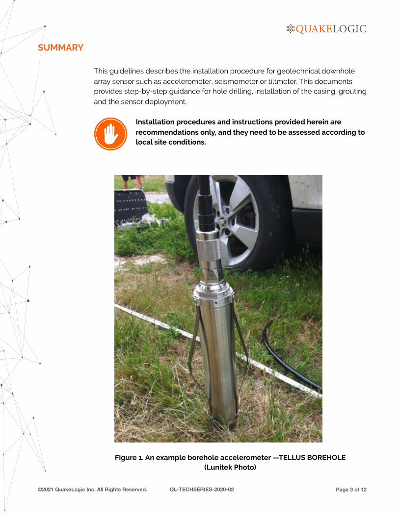
This guidelines describes the installation procedure for geotechnical downhole
array sensor such as accelerometer, seismometer or tiltmeter. This documents provides step-by-step guidance for hole drilling, installation of the casing, grouting
and the sensor deployment.
Installation procedures and instructions provided herein are
recommendations only, and they need to be assessed according to local site conditions.
Figure 1. An example borehole accelerometer —TELLUS BOREHOLE (Lunitek Photo)
©2021 QuakeLogic Inc. All Rights Reserved. QL-TECHSERIES-2020-02 Page � of �3 12

�
INSTALLATION PROCESS
Installation of seismic monitoring borehole casing shall consist of drilling into soil
and furnishing and installing PVC casings for seismic monitoring equipment (i.e., accelerometer, seismometer, tiltmeter) at downhole location.
The expert from QuakeLogic will mark the exact location for each
downhole.
Figure 2. Delaney Park Geotechnical Array in Anchorage, Alaska. Photo shows
locations of 5 boreholes and surface station (USGS photo)
©2021 QuakeLogic Inc. All Rights Reserved. QL-TECHSERIES-2020-02 Page � of �4 12
�
Installation of seismic monitoring casing includes the following operations, in the
following order:
a. Drill one 4.5-inch (11.5 cm) diameter hole for the deepest hole at each
downhole array location, and collect soil samples, and prepare a log of test borings and boring report.
b. Perform P-S suspension logging.
c. Drill 8-inch (20.5 cm) diameter hole for installation of casing.
d. Install 4-inch (10.2 cm) diameter screw joint PVC pipe casing, including
Bishops Hat end unit.
e. Grout the annulus between the 8-inch diameter hole and the 4-inch diameter casing and install pipe cap and enclosure.
Maximum deviation for sensor operation must remain within ±5
degrees.
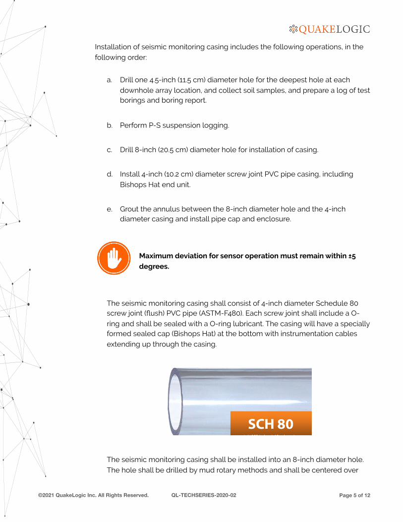
The seismic monitoring casing shall consist of 4-inch diameter Schedule 80 screw joint (flush) PVC pipe (ASTM-F480). Each screw joint shall include a O-
ring and shall be sealed with a O-ring lubricant. The casing will have a specially formed sealed cap (Bishops Hat) at the bottom with instrumentation cables
extending up through the casing.
The seismic monitoring casing shall be installed into an 8-inch diameter hole.
The hole shall be drilled by mud rotary methods and shall be centered over
©2021 QuakeLogic Inc. All Rights Reserved. QL-TECHSERIES-2020-02 Page � of �5 12
�
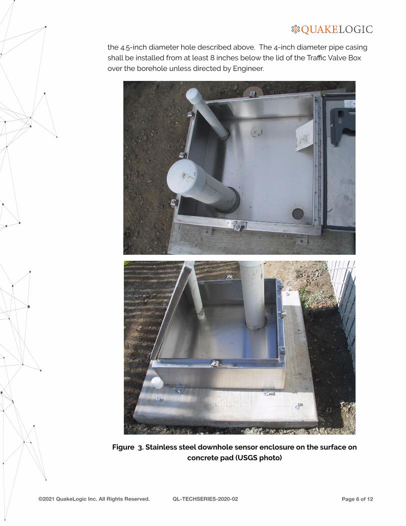
the 4.5-inch diameter hole described above. The 4-inch diameter pipe casing
shall be installed from at least 8 inches below the lid of the Traffic Valve Box
over the borehole unless directed by Engineer.
Figure 3. Stainless steel downhole sensor enclosure on the surface on
concrete pad (USGS photo)
©2021 QuakeLogic Inc. All Rights Reserved. QL-TECHSERIES-2020-02 Page � of �6 12
�
The inside of the casings must be kept clean, for instrument installation.
Clean water can be used in the casings to offset buoyancy during installation.
QuakeLogic expert will witness the installation and grouting of
the downhole casing and will camera them for cleanliness.
©2021 QuakeLogic Inc. All Rights Reserved. QL-TECHSERIES-2020-02 Page � of �7 12

�
SENSOR DEPLOYEMENT
Sensor installation should start with equipment preparation including sensor such
as borehole accelerometer. The sensor needs to be oriented according to the true north and set before inserted into the casing.
Figure 4. Installation of downhole sensor into the tubing (USGS photo)
The sensor is slowly dropped down to the bottom of the borehole. It should be noted that the tilt greater than 5 degrees may cause contamination of the
recorded data due to gravitational effects.
The sensor cable should never be bent but should instead slide into the hole perpendicular to the ground. The rule applies to both
the deployment and recovery of the sensor.
©2021 QuakeLogic Inc. All Rights Reserved. QL-TECHSERIES-2020-02 Page � of �8 12
�
We strongly recommend pouring sand to cover at least half part of the sensor,
where the sensor is located. It is not recommended to cover more than half the
length of the sensor as serious problems will arise in case you want to retrieve the sensor from the hole.
Pull the sensor a little before pouring the sand into the hole to
improve the vertical position of the sensor in the hole, this will help
ensure the vertical position.
©2021 QuakeLogic Inc. All Rights Reserved. QL-TECHSERIES-2020-02 Page � of �9 12
�
GROUTING At the bottom of the borehole, the casing string shall be supported 3 feet (1 m)
above the floor before grout is added. The grout shall be a mixture of cement-
bentonite and water according to the following proportions:
a. soft grout: two 90-lb (41-kilogram) sack of cement and one half 60-lb (27.4-kilogram) sack of bentonite per 50 gallons (189 liters) of water.
b. hard grout: five 90-lb (41-kilogram) sack of cement and 1 quarter 60-lb (27.4-kilogram) sack of bentonite per 50 gallons (189 liters) of water.
The grout mixture will be determined by the QuakeLogic expert.
Grout shall be pumped upwards from the bottom, around the outside of the casing to within 3 feet (1 m) of the surface. The cement shall be allowed to cure for
24 hours.
Grout shall be delivered at the low end of the void being filled by methods that
prevent the mixing of grout with water during charging of the grout delivery tubes and placement of the grout. Until at least 10-foot (3 m) of grout has been placed,
the tips of grout delivery tubes shall be within 6-inch (15 cm) of the bottom of the
void being filled. The grout delivery tubes may then be raised during grouting, providing that the embedment of the tips is maintained at least 6 feet (1.8 m)
below the top surface of the grout.
Sufficient grout shall be injected to fill the annular space between the casing and
the hole and be expelled at the top of the hole until there is no evidence of entrapped air or water. A minimum grout head of 2 feet (60 cm) shall be
maintained above the top of the hole until the grout has set.
All residues from the grouting operation shall be removed after completing the
grouting operations and shall be disposed of in accordance with all applicable local, state, and federal laws and regulations.
©2021 QuakeLogic Inc. All Rights Reserved. QL-TECHSERIES-2020-02 Page � of �10 12
�
ORIENTATION OF HORIZONTAL SENSORS
It is quite unlikely that the sensor has maintained the same orientation it had when
it was inserted into the hole, most likely it had twisted on itself and changed to an unknown orientation.
So, in essence, the easiest way to understand which is the correct orientation is to
use a correctly oriented triaxial surface seismometer and wait for a decent
magnitude earthquake or use an active seismic source.
Both sensors must be acquired synchronously. Subsequently, one can compare the signals and understand what is the displacement of the borehole with respect
to the surface.
If you need help for this, ask to our experts at QuakeLogic.
MISALIGNMENT CORRECTION
Once you know what the correct orientation of the borehole is, you may want to correct the measured misalignment. This can be easily done using a correction
factor directly on the recorders and also in several software for seismic monitoring
applications.
REFERENCES
KALKAN, E., WEN, W. AND HEO, Y. "Delaney Park Geotechnical Array Dynamic
Properties Inferred from The M7.1 2018 Anchorage Alaska Earthquake Sequence," ASCE J. Geotech. Geoenviron. Eng., 2021, 147(1): 04020150 (available online at
https://quakelogic.net/Pubs/129.pdf)
PEDRONI, M. “Lunitek – Recommendation for borehole installation”, Technical
Document, LT19-350-TEC-00-R0.
©2021 QuakeLogic Inc. All Rights Reserved. QL-TECHSERIES-2020-02 Page � of �11 12

�
©2021 QuakeLogic Inc. All Rights Reserved. QL-TECHSERIES-2020-02 Page � of �12 12
www.quakelogic.net
+1-916-258-3736
AI-POWERED EARTHQUAKE RISK MANAGEMENT SOLUTIONS
SERVING 24/7 AROUND THE GLOBE
USA | CaliforniaBulgaria | SofiaChina | BeijingGreece | AthensItaly | SarzanaMexico | Mexico City
Philippines | ManilaPuerto Rico | San JuanSri Lanka | Colombo Thailand | Pathum ThaniTurkey | Istanbul, Ankara UK | Glasgow
Proper monitoring, surveillance and maintenance can provide early detection and intervention—Emergency Response