installation manual - thor guard · the voice of thor external air horn alarm warning system may...
TRANSCRIPT
HYPERSTATIC SENSOR
INSTALLATIONMANUAL
HYPERSTATIC SENSOR INSTALLATION
Choosing the Sensor Location
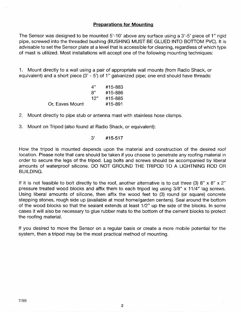
The location of the Sensor will be dependent upon the desired location of the THOR GUARDconsole, the type of existing roofing material, the design of the roof, and the proximity of otherequipment that may adversely affect the performance of the system. If a roof location is notpossible, the Sensor may be mounted on a post or pole, as long as it has a clear view of theatmosphere. The following should be considered during the pre-installation survey as to locatingthe Sensor:
· As close to the console as possible (200’ Max.).· At least 10’-15’ from lightning rods.· At least 15’-20’ from air conditioning units, vents, fans, etc.· At least 20’-30’ from other antennas; e.g. TV. VHF, etc.· As far from the trees as possible to discourage birds and spiders.· Outside a 30-degree angle from light poles or trees (trees absorb electrostatic field).· As far as possible from electric charger units or large transformers.· A metal roof can steal the energy from the Sensor so call the factory for advice.· High enough so that curious hands cannot inadvertently touch the Hyperstatic Plate
thereby setting off the system.· MAKE SURE THAT ANY MAST OR TRIPOD UTILIZED TO MOUNT THE SENSOR IS
NOT GROUNDED.· SENSOR MUST BE ACCESSIBLE FOR REGULAR CLEANING.
Running the T riaxial Cable
You have been supplied with a predetermined length of special triaxial cable which should accom-modate your installation. Hopefully the pre-installation survey correctly estimated your needs. Thepath available for the cable will also dictate the final location of the Sensor and Console. Apartfrom avoiding the obvious obstacles, attention should be given to the following:
· The cable does not carry any AC power, so in most instances it won’t be necessary to enclose it in conduit. However, local ordinances should be reviewed and requirements adhered to, always.
· When routing the cable, do not parallel lightning rod grounding wires.· Avoid sharp bends, metal edges, or anything that might tear outer jacket.· Conceal and secure as much as possible.· Avoid pulling too tightly and stretching the cable.· Take care to NOT damage connector by forcing it through tight places.
NOTE: IF YOU ALSO PLAN TO INSTALL A VOICE OF THOR ALARM SYSTEM IT WOULDBE ADVISABLE TO ALSO RUN THE COMM-LINK CABLE (6 COND.) TO THE ROOF AT THE
SAME TIME YOU RUN THE TRIAXIAL CABLE.HYPERSTATIC SENSOR INSTALLATION
17/99
HYPERSTATIC SENSOR INSTALLATION
Mounting Instructions
1. Choose the location and run the sensor cable (above).2. Select the mounting technique and prepare for installation (above).3. If mounting on a 1” galvanized pipe glue the enclosed reducer to sensor bottom.4. CABLE: You have been provided with a predetermined length of triaxial cable. If this cable
needs to be spliced, refer to page 9 (Sensor cable splice).5. Carefully thread the sensor onto the pipe stub and tighten.6. Coil any excess cable as a service loop and tie-wrap to something solid.7. After the THOR GUARD console is installed, and the sensor cable is attached, refer to
testing the sensor in the Operators Manual.
Maintenance and Cleaning
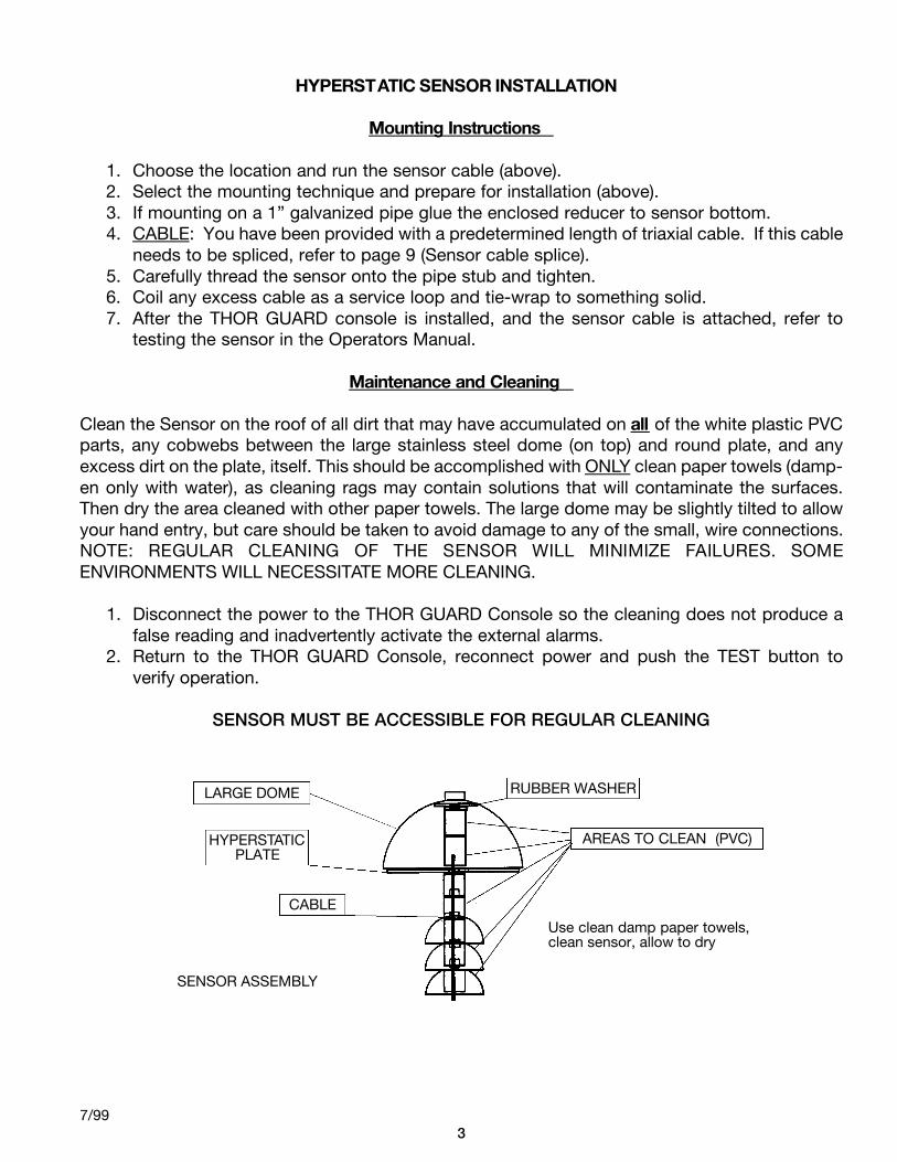
Clean the Sensor on the roof of all dirt that may have accumulated on all of the white plastic PVCparts, any cobwebs between the large stainless steel dome (on top) and round plate, and anyexcess dirt on the plate, itself. This should be accomplished with ONLY clean paper towels (damp-en only with water), as cleaning rags may contain solutions that will contaminate the surfaces.Then dry the area cleaned with other paper towels. The large dome may be slightly tilted to allowyour hand entry, but care should be taken to avoid damage to any of the small, wire connections.NOTE: REGULAR CLEANING OF THE SENSOR WILL MINIMIZE FAILURES. SOMEENVIRONMENTS WILL NECESSITATE MORE CLEANING.
1. Disconnect the power to the THOR GUARD Console so the cleaning does not produce afalse reading and inadvertently activate the external alarms.
2. Return to the THOR GUARD Console, reconnect power and push the TEST button toverify operation.
SENSOR MUST BE ACCESSIBLE FOR REGULAR CLEANING
37/99
LARGE DOME
HYPERSTATICPLATE
CABLE
SENSOR ASSEMBLY
RUBBER WASHER
AREAS TO CLEAN (PVC)
Use clean damp paper towels,clean sensor, allow to dry
The Voice of THOR external air horn alarm warning system may include the following components:
1. Master Alarm Control (MAC ) or VOT Base Console (VOT-BC ), with a connector cable to complete the link with the THOR GUARD Console.
2. Specified length of Comm-Link cable: Penn #3021, 6 cond., 18 awg, Shielded Type CM or CL3 75C[UL], or equivalent to link Base Console with Base Driver.
3. VOT Base Driver (VOT-BD ) including transmitter, battery, and transmitting antenna/strobe light kit.
4. VOT Horn Clusters (VOT-HC ) with specified length of compressor power cable.5. VOT Remotes (VOT-RC ) including receiver, battery, and receiving antenna/strobe light kit.
Installation
Master Alarm Control (VOT-MAC)
1. Position the MAC on top of the THOR GUARD console but DO NOT connect the power adapter to AC as yet. It would be a good idea to now refer to the MAC Operations Manual!
2. Plug the VOT/THOR GUARD Connector Cable into the output of the THOR GUARD (5 pin) and the input of the MAC (6 pin).
3. If you did not run the Comm-Link before (with the Sensor cable) it needs to be run now.4. Connect “like” colored wires to pigtail with connector as provided (solder and tape
securely).5. Apply power and make Menu selections ( see MAC Operations Manual).
47/99

VOT Base Driver (VOT -BD) & Hor n Cluster (VOT -HC)
The L150 or the VOTMAC is used to control the VOTBD. You have been supplied a “pigtail” cable thatconnects to the rear of the console in the location VOTBD. Solder & tape each wire from the Comm-Linkcable to the pigtail. The VOTBD must be installed before connecting Comm-Link cable to the console.
The VOT Base Driver controls the base VOT-HC and contains the RF Computer/Transmitter totransmit to the VOT- R C ’s. The Base should be located within the lengths of the cable supplied to the HornCluster and to the RF antenna. Excess compressor cable should be removed. Do not alter the RF cablelength. The RF antenna may be mounted on the same mast (pipe) that holds the base VOT-HC or, ifutilized, one of the tripod legs, or mounted separately. The standard length for both the compressor cableand the RF cable is 18Ft. Cable lengths of 40Ft. are available for both RF and compressor cable. Whensecuring cables, if using staples, do not attach tightly, as damage may occur.N O T E : You will need to access the VOT-BD box to check/change the battery and theComputer/Transmitter so it needs to be accessible.
1. The positioning of the Base Horn Cluster to achieve maximum coverage will probably be the controlling factor (remember, sound rises, so higher is not really better). The individual horns may be adjusted to optimize coverage.
2. Determine the type of mounting hardware required for the location selected (above) as well as the length of 1” pipe to be utilized to mount the Horn Cluster.
3. Screw the Horn Cluster onto the 1” pipe after feeding the attached compressor power cable down the pipe.
4. Mount the Base Antenna (if there are to be remotes) to the 1” pipe or otherwise, per theinstructions in kit.
5. Attach the entire assembly to the desired mounting location. Allow for a service loop leaving the pipe.
6. Mount the VOT-BD box. The Comm-Link cable from the VOT-MAC below should already be available at this location. Remove 1Ft. gray insulation from this cable. Cut off brown wire.
7. Run Compressor Power Cable (18Ft. provided) and the VOT-MAC Comm-Link Cable into the VOT-BD box through inputs (bottom of box) and secure the RF cable connector to theconnector provided outside. Insure the RF connector is correctly seated and tighten firmly.
8. Solder and tape Comm-Link White, Blue, and Green wire to the matching colors of thethree-conductor right angle plug provided. Then plug right angle phone jack into the slot on the left side of the Transmitter.
9 . Insert the Red and Black battery charger wires to the Relay Bracket in the appropriate slots marked “solar”.
10. Insert Compressor Power Cable ends into marked slots on Relay Bracket; match colors as marked.
11.Horn Set 1 (Red + Black -), Horn Set 2 (Orange + Blue -).12. If supplied, attach strobe light to the top of the Relay Bracket where labeled. Observe
correct colors.13.Connect Red (+) lead to 12-volt battery. Insure tight connection.14. R e t u rn to the MAC and apply power. Then re t u rn to Base Driver and turn on the
Computer/Transmitter by pushing the blue side button on the right side of the transmitter. The Center Bar on the display will blink if correctly connected. A letter “E” blinking will indicate a connection problem. Check your wire splice, is right angle plugged in firmly? If you then press and hold the “Horn Test” (black button located on transmitter) for 5 seconds, the horns should sound. If a strobe light is attached, the light will turn on. Release button to stop test. You may also press the blue button on the Relay Bracket to perform the same test.
15.After Remotes are installed test the entire system (Red Alert), and re-test regularly!
57/99
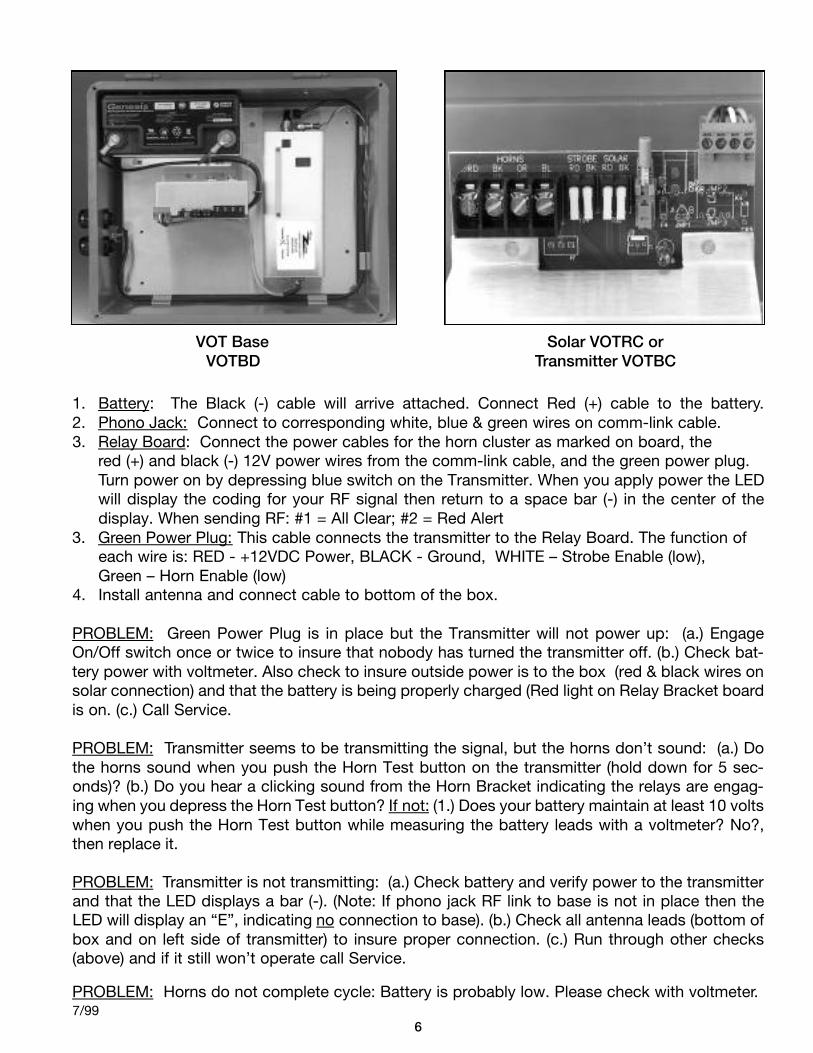
1. Battery: The Black (-) cable will arrive attached. Connect Red (+) cable to the battery.2. Phono Jack: Connect to corresponding white, blue & green wires on comm-link cable. 3. Relay Board: Connect the power cables for the horn cluster as marked on board, the
red (+) and black (-) 12V power wires from the comm-link cable, and the green power plug. Turn power on by depressing blue switch on the Transmitter. When you apply power the LEDwill display the coding for your RF signal then return to a space bar (-) in the center of thedisplay. When sending RF: #1 = All Clear; #2 = Red Alert
3. Green Power Plug: This cable connects the transmitter to the Relay Board. The function of each wire is: RED - +12VDC Power, BLACK - Ground, WHITE – Strobe Enable (low), Green – Horn Enable (low)
4. Install antenna and connect cable to bottom of the box.
PROBLEM: Green Power Plug is in place but the Transmitter will not power up: (a.) EngageOn/Off switch once or twice to insure that nobody has turned the transmitter off. (b.) Check bat-tery power with voltmeter. Also check to insure outside power is to the box (red & black wires onsolar connection) and that the battery is being properly charged (Red light on Relay Bracket boardis on. (c.) Call Service.
PROBLEM: Transmitter seems to be transmitting the signal, but the horns don’t sound: (a.) Dothe horns sound when you push the Horn Test button on the transmitter (hold down for 5 sec-onds)? (b.) Do you hear a clicking sound from the Horn Bracket indicating the relays are engag-ing when you depress the Horn Test button? If not: (1.) Does your battery maintain at least 10 voltswhen you push the Horn Test button while measuring the battery leads with a voltmeter? No?,then replace it.
PROBLEM: Transmitter is not transmitting: (a.) Check battery and verify power to the transmitterand that the LED displays a bar (-). (Note: If phono jack RF link to base is not in place then theLED will display an “E”, indicating no connection to base). (b.) Check all antenna leads (bottom ofbox and on left side of transmitter) to insure proper connection. (c.) Run through other checks(above) and if it still won’t operate call Service.
PROBLEM: Horns do not complete cycle: Battery is probably low. Please check with voltmeter.
67/99
VOT BaseVOTBD
Solar VOTRC orTransmitter VOTBC
VOT Remote (VOT -RC) & Hor n Cluster (VOT -HC)
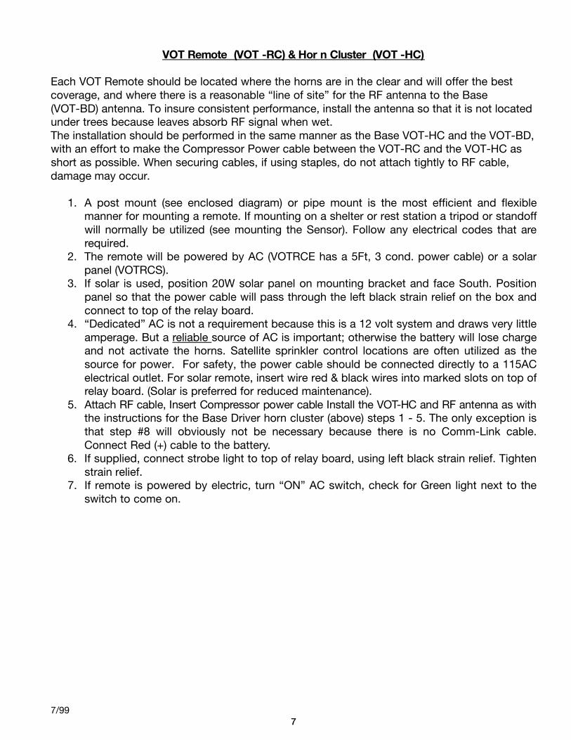
Each VOT Remote should be located where the horns are in the clear and will offer the bestcoverage, and where there is a reasonable “line of site” for the RF antenna to the Base(VOT-BD) antenna. To insure consistent performance, install the antenna so that it is not locatedunder trees because leaves absorb RF signal when wet.The installation should be performed in the same manner as the Base VOT-HC and the VOT-BD,with an effort to make the Compressor Power cable between the VOT-RC and the VOT-HC asshort as possible. When securing cables, if using staples, do not attach tightly to RF cable,damage may occur.
1. A post mount (see enclosed diagram) or pipe mount is the most efficient and flexiblemanner for mounting a remote. If mounting on a shelter or rest station a tripod or standoffwill normally be utilized (see mounting the Sensor). Follow any electrical codes that arerequired.
2. The remote will be powered by AC (VOTRCE has a 5Ft, 3 cond. power cable) or a solar panel (VOTRCS).
3. If solar is used, position 20W solar panel on mounting bracket and face South. Position panel so that the power cable will pass through the left black strain relief on the box and connect to top of the relay board.
4. “Dedicated” AC is not a requirement because this is a 12 volt system and draws very little amperage. But a reliable source of AC is important; otherwise the battery will lose charge and not activate the horns. Satellite sprinkler control locations are often utilized as the source for power. For safety, the power cable should be connected directly to a 115AC electrical outlet. For solar remote, insert wire red & black wires into marked slots on top of relay board. (Solar is preferred for reduced maintenance).
5. Attach R F cable, Insert Compressor power cable Install the VOT-HC and RF antenna as with the instructions for the Base Driver horn cluster (above) steps 1 - 5. The only exception is that step #8 will obviously not be necessary because there is no Comm-Link cable. Connect Red (+) cable to the battery.
6. If supplied, connect strobe light to top of relay board, using left black strain relief. Tighten strain relief.
7. If remote is powered by electric, turn “ON” AC switch, check for Green light next to the switch to come on.
77/99
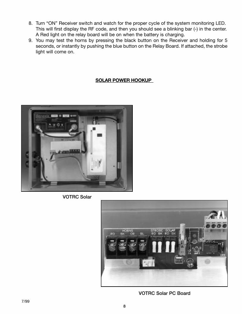
8. Turn “ON” Receiver switch and watch for the proper cycle of the system monitoring LED. This will first display the RF code, and then you should see a blinking bar (-) in the center.A Red light on the relay board will be on when the battery is charging.
9. You may test the horns by pressing the black button on the Receiver and holding for 5 seconds, or instantly by pushing the blue button on the Relay Board. If attached, the strobelight will come on.
SOLAR POWER HOOKUP
87/99
VOTRC Solar
VOTRC Solar PC Board
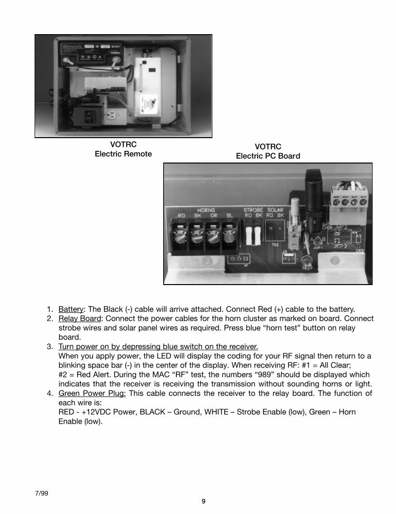
1. Battery: The Black (-) cable will arrive attached. Connect Red (+) cable to the battery.2. Relay Board: Connect the power cables for the horn cluster as marked on board. Connect
strobe wires and solar panel wires as required. Press blue “horn test” button on relay board.
3. Turn power on by depressing blue switch on the receiver.When you apply power, the LED will display the coding for your RF signal then return to a blinking space bar (-) in the center of the display. When receiving RF: #1 = All Clear;#2 = Red Alert. During the MAC “RF” test, the numbers “989” should be displayed which indicates that the receiver is receiving the transmission without sounding horns or light.
4. Green Power Plug: This cable connects the receiver to the relay board. The function ofeach wire is:RED - +12VDC Power, BLACK – Ground, WHITE – Strobe Enable (low), Green – HornEnable (low).
97/99
VOTRCElectric Remote
VOTRCElectric PC Board
PROBLEM: Green Power Plug is in place but the Receiver will not power up: (a.) Engage BlueOn/Off switch once or twice to insure that nobody has turned the receiver off. (b.) Check batterypower with voltmeter. Also check to insure outside power is to the box (either solar or local AC)and that the battery is being properly charged. (c.) Place positive voltmeter lead on Power PlugRed, Negative on Black. Should show approx. 12 volts. (d.) Call Service for technical support.
PROBLEM: Receiver seems to be receiving the transmitted signal, (display has a blinkingnumber) but the horns don’t sound: (a.) Do the horns sound when you push the blue horn testbutton on the relay board? (b.) Do you hear a clicking sound from the Horn Bracket indicating therelays are engaging when you depress the Horn Test button? If not: (1.) Does your batterymaintain at least 10 volts when you push the Horn Test button while measuring the battery leadswith a voltmeter? No?, then replace it. (c.) Apply horn cable to the battery directly, checking eachset of horns, Horn Set 1(Red +, Black -), Horn Set 2 (Orange +, Blue -). Replace the Horn clusterif weak or defective horn set. If there are multiple remotes, exchange receiver with a known goodRemote, otherwise request a replacement.
PROBLEM: Receiver is not receiving the transmitted signal or does not work consistently: (a) Make certain antenna is clear from tress. (b.) Check all antenna leads (bottom of box andon left side of receiver) for proper connection. Check battery & verify power to the receiver, andcorrect display. (Note: You can switch Receiver with another one that you know is working toverify antenna operation.)
PROBLEM: Horns do not complete cycle: Battery is probably low. Please check with voltmeter.
107/99

VOTBDNH & VOTRCNH
The VOTBDNH is for locations where there are no base horns. There is 40Ft. of RF cableincluded.Attach the box to the sensor mounting bracket if possible. When securing cable, if usingstaples, do not attach tightly, as damage may occur. Do not alter the RF cable length.
VOTBDNH1. Mount the box to the selected location using “U” bolts or lag screws.2. After the antenna has been mounted at the selected location, remove the black grommet
from the box. Place the cable inside the grommet and reattach to box. Secure the RFconnector to the transmitter. If desired, apply RTV to the opening.
3. Remove 1Ft. of gray insulation from the Comm-Link cable. Bring cable into box, securewith bushing.
4. Attach wires to the edge of the board in each of the marked location. (Power /Comm-link). Lift the white lever and press wire in and then push lever down. Cut brown wire off.
5. If supplied, connect strobe light as indicated on pc board.6. The cable to the VOTMAC needs to be spliced and connected now. Apply power to the
VOTMAC & then press the blue power button to turn on the transmitter.7. The display will indicate the RF site and then display a blinking (-). A letter “E” indicates a
wiring problem.
117/99
VOTBDNH Box
VOTBDNH PC Board
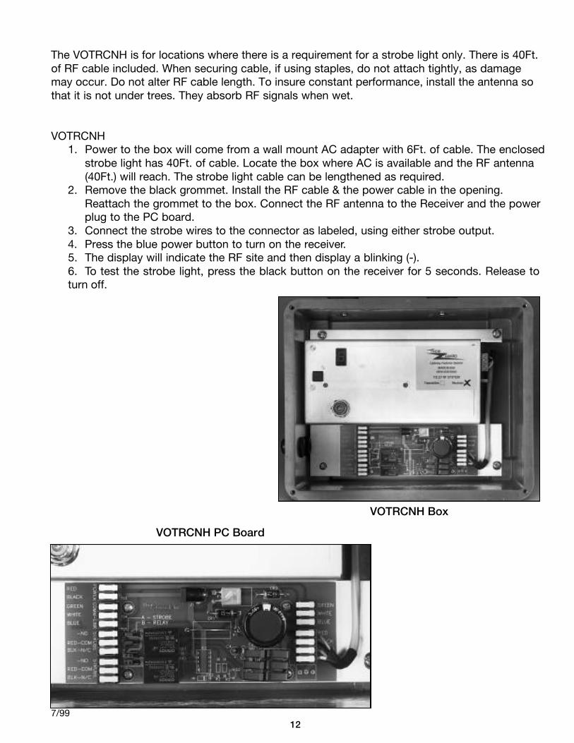
The VOTRCNH is for locations where there is a requirement for a strobe light only. There is 40Ft.of RF cable included. When securing cable, if using staples, do not attach tightly, as damagemay occur. Do not alter RF cable length. To insure constant performance, install the antenna sothat it is not under trees. They absorb RF signals when wet.
VOTRCNH1. Power to the box will come from a wall mount AC adapter with 6Ft. of cable. The enclosed
strobe light has 40Ft. of cable. Locate the box where AC is available and the RF antenna (40Ft.) will reach. The strobe light cable can be lengthened as required.
2. Remove the black grommet. Install the RF cable & the power cable in the opening. Reattach the grommet to the box. Connect the RF antenna to the Receiver and the power plug to the PC board.
3. Connect the strobe wires to the connector as labeled, using either strobe output.4. Press the blue power button to turn on the receiver.5. The display will indicate the RF site and then display a blinking (-).6. To test the strobe light, press the black button on the receiver for 5 seconds. Release toturn off.
127/99
VOTRCNH Box
VOTRCNH PC Board
INSTALLATION INSTRUCTIONSTHOR GUARD ANTENNA PACKAGE
The enclosed antenna(s) have been tuned to the RF frequency of your transmitter and remotes.This kit should include the following items:
1. (1) white antenna.2. 18’ RG58 antenna cable.3. 12” aluminum mounting-bracket with antenna & cable connectors attached.4. Approx. 8’ of insulated ground plane wire with screw connector on one end.5. Mounting “U” bolts to mount to 1” galvanized pipe holding the horn cluster.
Firmly screw white antenna into its receptacle on mounting bracket.Firmly screw one end of the RG58 antenna cable onto the connector beneath the white anten-na. After mounting “mounting bracket” tie-wrap to galvanized pipe and attach other end toreceptacle in gray Hoffman Box.Attach the 8’ ground plane wire by its screw to the mounting bracket in the hole provided nextto the four “U” bolt mounting holes. It is important that this wire be fully extended down thepole (and along the ground or roof if necessary). It may be secured by the same tie-wraps onthe pole utilized to secure the antenna cable above. This wire however, should be run on theopposite side of the pole, if possible.Mount the “mounting bracket” on either the 1” galvanized pipe (utilizing the 2 “U” bolts) ordirectly to a wood post using screws, if desired. This should be located as high as possibleunder the horn cluster with the antenna passing between two of the horns.NOTE: Coat antenna and ground plane connections with a light amount of RTV.
137/99
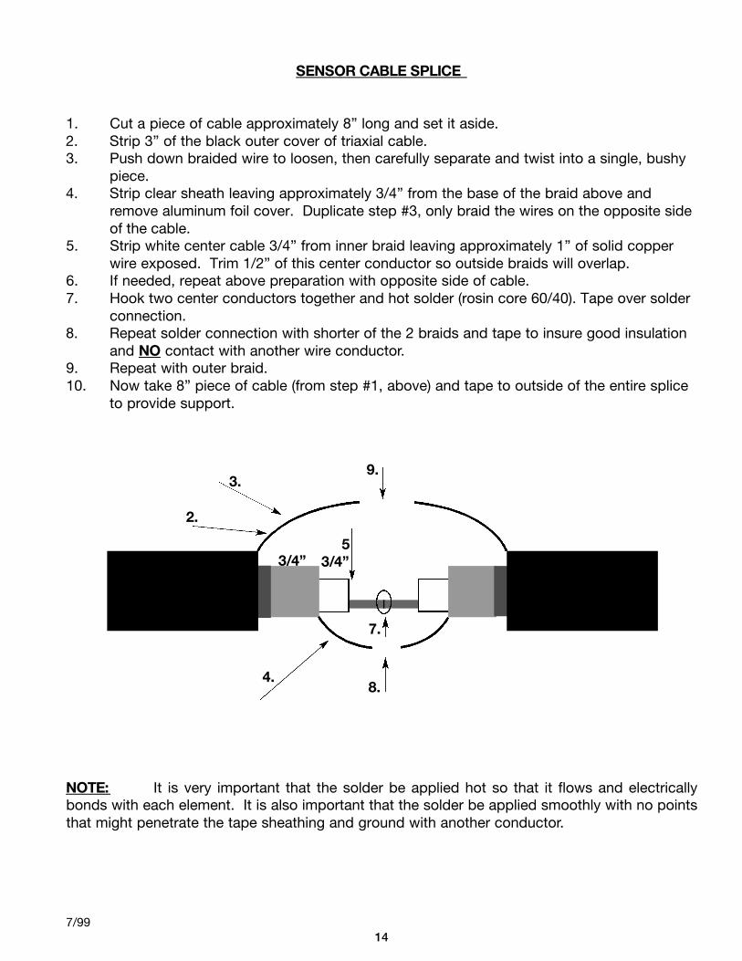
SENSOR CABLE SPLICE
1. Cut a piece of cable approximately 8” long and set it aside.2. Strip 3” of the black outer cover of triaxial cable.3. Push down braided wire to loosen, then carefully separate and twist into a single, bushy
piece.4. Strip clear sheath leaving approximately 3/4” from the base of the braid above and
remove aluminum foil cover. Duplicate step #3, only braid the wires on the opposite side of the cable.
5. Strip white center cable 3/4” from inner braid leaving approximately 1” of solid copper wire exposed. Trim 1/2” of this center conductor so outside braids will overlap.
6. If needed, repeat above preparation with opposite side of cable. 7. Hook two center conductors together and hot solder (rosin core 60/40). Tape over solder
connection.8. Repeat solder connection with shorter of the 2 braids and tape to insure good insulation
and NO contact with another wire conductor.9. Repeat with outer braid.10. Now take 8” piece of cable (from step #1, above) and tape to outside of the entire splice
to provide support.
NOTE: It is very important that the solder be applied hot so that it flows and electricallybonds with each element. It is also important that the solder be applied smoothly with no pointsthat might penetrate the tape sheathing and ground with another conductor.
147/99
53/4”
7.
8.4.
9.3.
2.
3/4”