installation manual - ipexna.com · installation manual flat : ... phases of the novaform...
TRANSCRIPT

Folded/Formed PVC Pipe for Existing Sewer & Culvert Rehabilitation
INSTALLATION MANUAL
FLAT : 6" to 12" | H-SHAPE: 15" to 30"

2
3 Proprietary Notice 4 Introduction4 Safety5 Description of Equipment7 The NovaForm PVC Liner Process7 1. Preparing
a. Getting Startedb. Equipment Setupc. Linder Pull Head Setup (for 6” to 12” Liners with Flat profile)d. Preparing Liner Pull Head (for 6” to 12” Liners with Flat profile)e. Liner Pull Head Setup (for 15” to 30” Liners with H-profile)f. Preparing Liner Pull Head (for 15” to 30” Liners with H-profile)
12 2. Conditioninga. Internal Heating with Optional Coil Rotationb. External Heating
13 3. Pullinga. Preparing Liner for Pullingb. Preparing “A” Side for Full Pullc. Pull Liner
14 4. Processinga. Pipe Stress Release/Relaxationb. Insert "B" Side Plugc. Insert "A" Side Plugd. Heatinge. Expansion/Cooling
16 5. Finishing
17 NovaForm Processing Procedures Reference Chart19 PVC Liner Process Record
CONTENTS

3
Proprietary Notice
This Manual and all of its content are the property of IPEX. This Manual has been provided by IPEX and is
subject to confidentiality. No reproduction in any form of any portion of this Manual can be made without
the prior written consent of IPEX.
© IPEX 2017

4
This manual provides step-by-step instructions necessary to successfully and safely install NovaForm PVC Liner.
It is important that you pay particular attention to the safety section of this manual. IPEX makes your safety our first priority at all times.
Each installation will require procedural modifications which cannot be made without an intimate knowledge of all conditions pertaining to a specific installation. Since IPEX does not and cannot act as a consultant in this regard, responsibility for use of information or advice herein or otherwise provided to determine installation procedures for a specific installation rests solely with the installer.
Installers receive training and technical support from authorized representatives of IPEX to promote competency and mutual confidence in the installer’s ability to make proper installation decisions. If an installer desires to attempt an installation with unfamiliar or new variables, the installer is advised to contact IPEX to draw upon the cumulative knowledge of the manufacturer and the other installers.
Installers are solely responsible to ensure that their personnel follow all applicable local and national laws
relating to the installation of NovaForm PVC Liners.
Introduction
Safety
Be aware that machinery can crush your hands, or anything else that might be caught in certain areas of the machines while they are in operation.
As it is used during various stages of the NovaForm PVC Liner Process, steam should be carefully directed to prevent exposure to skin. Handling of hoses and plugs under pressure should be limited at all times.

5
Used to generate steam required for the conditioning and processing phases of the NovaForm installation. A boiler should be housed in a trailer for mobility. It should also include a water reservoir and water feed pump.
c. Boiler
Product is heated in the conditioning trailer/A-frame prior to pulling into the existing host pipe.
i. 6" – 12": Internal heating onlyii. 15" – 30": External heating only
4' wide by 8' tall. Larger reels are available upon request.
b. Conditioning Trailer/ A-Framea. Product Reel
Rollers are used to help guide the product from the conditioning trailer/A-frame to the host pipe and can be set up at both manholes or any other bending impediments.
e. Rollers
Used to pull product from product reel through host pipe.
d. Winch
Used to drain liquid from a hostpipe, sewer manhole or drainage ditch.
f. Sump Pump
Used for processing pipe. The plugs are inserted into the pipe ends and inflated. Steam is passed through the plug into the host pipe during the processing phase. 2 plugs are required per size. Industry standard plugs are readily available from third party suppliers.
g. Plugs
The air compressor is used to supply air for plug inflation andproduct processing. In the processing stage, the air supplied is used to cool and harden the installed liner.
h. Air Compressor
Description of Equipment
6
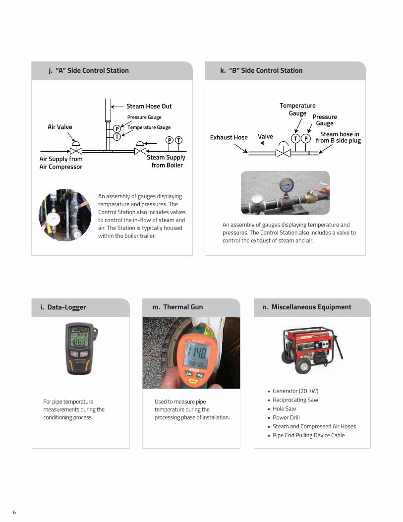
• Generator (20 KW)• Reciprocating Saw • Hole Saw • Power Drill• Steam and Compressed Air Hoses• Pipe End Pulling Device Cable
An assembly of gauges displaying temperature and pressures. The Control Station also includes valves to control the in-flow of steam and air. The Station is typically housed within the boiler trailer.
An assembly of gauges displaying temperature and pressures. The Control Station also includes a valve to control the exhaust of steam and air.
j. “A” Side Control Station k. “B” Side Control Station
For pipe temperature measurements during the conditioning process.
i. Data-Logger
Used to measure pipe temperature during the processing phase of installation.
m. Thermal Gun n. Miscellaneous Equipment
Air Valve
Steam Hose OutPressure Gauge
Temperature Gauge
Steam Supplyfrom Boiler
Air Supply fromAir Compressor
PT
TP Exhaust Hose Valve
TemperatureGauge Pressure
GaugeSteam hose in
from B side plugT P
7
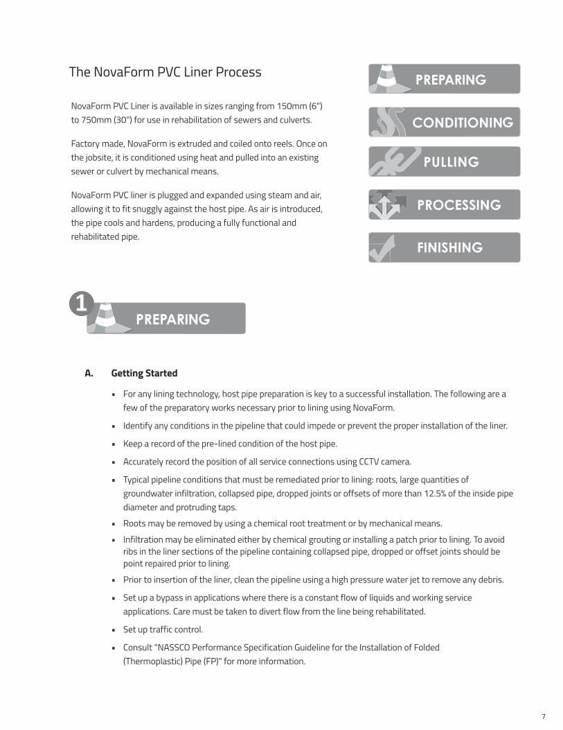
A. Getting Started
• For any lining technology, host pipe preparation is key to a successful installation. The following are a few of the preparatory works necessary prior to lining using NovaForm.
• Identify any conditions in the pipeline that could impede or prevent the proper installation of the liner.
• Keep a record of the pre-lined condition of the host pipe.
• Accurately record the position of all service connections using CCTV camera.
• Typical pipeline conditions that must be remediated prior to lining: roots, large quantities of groundwater infiltration, collapsed pipe, dropped joints or offsets of more than 12.5% of the inside pipe diameter and protruding taps.
• Roots may be removed by using a chemical root treatment or by mechanical means.
• Infiltration may be eliminated either by chemical grouting or installing a patch prior to lining. To avoid ribs in the liner sections of the pipeline containing collapsed pipe, dropped or offset joints should be point repaired prior to lining.
• Prior to insertion of the liner, clean the pipeline using a high pressure water jet to remove any debris.
• Set up a bypass in applications where there is a constant flow of liquids and working service applications. Care must be taken to divert flow from the line being rehabilitated.
• Set up traffic control.
• Consult "NASSCO Performance Specification Guideline for the Installation of Folded (Thermoplastic) Pipe (FP)" for more information.
1
NovaForm PVC Liner is available in sizes ranging from 150mm (6") to 750mm (30") for use in rehabilitation of sewers and culverts.
Factory made, NovaForm is extruded and coiled onto reels. Once on the jobsite, it is conditioned using heat and pulled into an existing sewer or culvert by mechanical means.
NovaForm PVC liner is plugged and expanded using steam and air, allowing it to fit snuggly against the host pipe. As air is introduced, the pipe cools and hardens, producing a fully functional and rehabilitated pipe.
The NovaForm PVC Liner Process

8
B. Equipment Setup
• Already loaded with the product reel, position conditioning trailer/A-frame at the “A” side (upstream manhole).
• Set up and start boiler; connect steam hose from boiler to conditioning trailer/A-frame.
• Position the winch.
• Install roller on the B-side.
• Prepare all accessories and tools on the “A” and “B” side ; plugs, reciprocating saw, grinder, thermal gun, tarp, generator, etc.
C. Liner Pull Head Setup (For 6" to 12" Liners with Flat profile)
• In order to successfully pull the liner through the host pipe, it is necessary to prepare a strong, yet flexible pull head.
• The following items will be necessary and can be purchased from any sling/rigging supplier:
1. Wire rope cable (aircraft cable) with Min. 4:1 Breaking to Working Load Limit
• Specifications: Galvanized or Stainless Steel, 7 x 19 Multi-strand construction, with thimble loops on each end
• Thickness: 1/4" diameter, 2,600 lb rating for basket pulling setup. 1/4" for thimble.
• Length will vary according to liner diameter:
» 6" – 10 ft minimum
» 8" – 12 ft minimum
» 10" – 14 ft minimum
» 12" – 16 ft minimum
2. Threaded Quick-links with Min. 4:1 Breaking to Working Load Limit
• Specifications: Galvanized or Stainless Steel, 1/4" minimum thickness, threaded, 880lb load limit
3. Anchor Shackle with
screw pin with Min. 4:1 Breaking to Working Load Limit
• Specifications: Galvanized or Stainless Steel, 1/2" minimum thickness, threaded, 4,000 lb load limit

9
D. Preparing Liner Pull Head
1. Prepare product for cable attachment by softening, folding and duct taping pipe end.
2. Cut end of liner in a V profile with a reciprocating saw.
3. Drill two 1" overlapping holes in fold of liner, approximately 1” back from the end.
4. Wrap wire cable rope around liner at the start of the folded section, and twist on itself once.
5. Continue wrapping cable around folded pipe, and securing the crossed sections using threaded Quick-links, both at the top and bottom of liner.
6. Once the end of the liner is reached, ensure that remaining cable loop ends are the same length, and if not, adjust wraps and Quick-links accordingly. Then, feed both loop ends through drilled hole, one at a time.
7. Secure the two cable loop ends to the shackle by inserting the shackle pin through cable loops and threading it closed.

10
E. Liner Pull head setup (For 15” to 30” Liners with H-profile)
• When pulling through a culvert or other pipe that exits horizontally through an open ended outlet, standard chains can be used and inserted through drilled out holes in the liner pull head.
• Specifications: Steel, Grade 80, 3/8”, 7,100lb load limit
• Length: 5ft minimum
• When pulling in a sanitary/storm sewer line that exits vertically through a manhole or catch basin, the following items will be required:
1. Wire rope cable (aircraft cable) with Min. 4:1 Breaking to Working Load Limit
• Specifications: Galvanized or Stainless Steel, 6 x 19 Multi-strand construction, with thimble loops on each end
• Thickness: 3/8” diameter, 5,800lb rating for basket pulling setup. 3/8” for thimble.
• Length will vary according to liner diameter:
» 15”/18” – 16ft/5m minimum» 24”/30” – 19ft/6m minimum
2. Threaded Quick-links with Min. 4:1 Breaking to Working Load Limit
• Specifications: Galvanized or Stainless Steel, 5/16” minimum thickness, threaded, 1525lb load limit, 3/8” Pin opening
3. Anchor Shackle with screw pin with Min. 4:1 Breaking to Working Load Limit
• Specifications: Galvanized or Stainless Steel, 5/8” minimum thickness, threaded, 6,500lb load limit

11
F. Preparing Liner Pull head (For 15” to 30” Liners with H-profile)
1. Horizontal exit from host pipe (Culverts):
• Cut the ends of the liner in a V-shape to profile the end of the pull head.
• Drill two 1” holes on either side of the liner, approximately 2"-3" behind the V profiled section.
• Make sure that the holes are drilled through both folds of the liner, so that the chain passes through completely. This ensures that the pull head will “close” under tension during the pull and will not open (see below).
2. Vertical exit from host pipe (Sanitary/Storm sewers):
• Cut the ends of the liner in a V-shape to profile the end of the pull head.
• Drill a 2” hole in the center of the liner, approximately 4” behind the V profiled section. Make sure that the hole is drilled through both folds of the liner, so that both ends of the wire rope can pass through completely. This ensures that the pull head will “close” under tension during the pull.
• Wrap the wire cable around the liner and secure using Quick-Links, as for the flat (6” to 12”) liners.
• Secure the two cable loop ends to the shackle by inserting the shackle pin through cable loops and threading it closed.

12
Open steam valve directing steam into the Conditioning trailer/A-Frame. Adjust valve to required steam pressure and temperature as detailed below.
6" – 12" Coil heating – Internal Heating with Optional Coil Rotation
• With the reel in the stationary position, connect steam hose to black conditioning plug.
• Cover liner with tarp and start with 15 psi of steam until steam comes out of the liner pull head.
• Once steam comes out for 1 minute, reduce steam pressure to 5 psi.
• Begin reel rotation at 15 RPM, if equipped with optional electric or hydraulic drive motor.
• Heating time is 20 minutes for coils of 350 ft. or less
• Add 10 minutes for every additional 100 ft. on a coil
15" – 30" Coil heating – External Heating
• With the reel inside of a steaming trailer or under a tarp, connect steam hose to heating manifold.
• Open steam to 5 PSI and heat the coil for the times listed below:
2
NOTE: Colder ambient temperatures and wind chill will affect above times and will require additional heating times. Good practice is to check liner temperature at various locations on the reel every 60 minutes.
Reel Size 4ft wide reel – 2.5 hours 6ft wide reel – 3.25 hours 8ft wide reel – 4 hours
Liner Sizes
15" up to 400ft 15" up to 650ft 15" up to 1200ft18" up to 200ft 18" up to 490ft 18" up to 1000ft24" up to 150ft 24" up to 255ft 24" up to 480ft30" up to 125ft 30" up to 185ft 30" up to 350ft

13
B. Preparing “A” Side for Full Pull
C. Pull Liner
• Begin pulling using winch at a faster speed. Typical pulling speed is between 100 – 150 FPM.
• Carefully monitor pulling speed. The pipe should be pulled through the host pipe at a speed dependent upon field conditions and host pipe material.
• Keep the reeled pipe in conditioning trailer or A-Frame taught with minimal sagging during pull.
• Lubricate liner continuously throughout pull.
• Once liner reaches B-Side, continue pulling until pipe is 6 feet past the manhole cover opening, or as high as the winch can pull.
• If the liner requires more power to pull around the B-side roller, set the winch into low gear setting (i.e. higher pull force).
3
• Lubricate host pipe liberally at entrance using IPEX pipe lubricant, vegetable oil or diluted dish soap.
• Using winch, slowly pull liner into manhole opening until the pull head is inserted into the host pipe.
• Ensure liner is free from any kinks and bends.
A. Preparing Liner for Pulling• Set up communication channel between
“A” and “B” side operators.
• Shut off stream.
• Open reel trailer doors or remove tarp.
• Ensure liner pull head is soft and flexible; if not heat longer until pull head is soft (170 OF minimum).
• Attach winch cable to pipe end cable.

14
A Pipe Stress Release/Relaxation
• During the pull of the liner, there will be a limited amount of stretching of the liner which will occur. This is based on several factors such as: host pipe length and material (which will affect friction); lubricant; liner temperature during pull; ambient temperature in host pipe; offset joints; winch power and pulling speed. In order to remove the residual stress caused by the pulling and to allow the liner to relax back into the host pipe, procedures MUST be followed:
4
1. Keep tension on the liner with the winch on the B-side, in order to allow for the pipe relaxation to take place from the A-side. The liner will be fed off the reel at the A-side as liner contracts into the host pipe, so keeping slack on the reel is critical.
2. Open steam valve providing a limited amount of pressure, typically between 3 – 5 psi showing on the A-side pressure gauge. Steam will vent off to the atmosphere on the B-side, through the pull head.
3. Continue with limited steam until liner movement into the host pipe at the A-side has slowed to less than 2" movement in a 5 minute period. This will be observed by using a marking on the liner and reference point at the bottom of the manhole.
4. Release tension on the liner on the B-side using the winch, and allow for approximately 1 – 2 ft. of relaxation back into host pipe.
5. Shut off steam and allow liner to deflate in the host pipe. After 1 minute, re-open the steam valve at 3 – 5 psi and observe if any further movement of liner occurs at both A and B manholes. If none, relaxation is complete.

15
B. Insert “B” Side Plug
C. Insert “A” Side Plug
• Starting on the “B” side, connect steam hose to plug and position close to pipe end.
• Encapsulate the plug and liner in a tarp.
• Open steam valve allowing the pipe end to be softened.
• Once softened, turn off steam valve.
• Fully insert plug into softened pipe end.
• Cut “A” side pipe from reel leaving 6 feet of pipe past the manhole cover opening. Alternatively, cut a slit on one side of liner and insert plug.
• Position plug on “A” side close to pipe end.
• Encapsulate the plug and liner in a tarp.
• Open steam valve allowing the pipe end to be softened.
• Once softened, turn off steam valve.
• Fully insert plug into softened pipe end.
• Attach compressed air line to plug / plug bladder.
• Inflate to recommended pressure, provided by plug supplier.
• Apply cold water to the plugged pipe end to harden.
• Install safety device as illustrated.
• In the manhole, do not have the liner weight resting on the bend/kink. Prevent this by holding up the liner by tying it off to the A-frame or Steam box. A fall arrest tripod that supports the weight can also be used.
• Attach compressed air line to plug / plug bladder.
• Inflate to recommended pressure provided by plug supplier.
• Apply cold water to the plugged pipe end to harden.
• Install safety device as illustrated.
• Keep the liner held in the air with the winch or rope, to keep the liner weight from resting on the liner kink or bend.

16
• For detailed information on the proper procedure to “Finish” a PVC liner installation, please review section 3.3 of the NASSCO Performance Specification Guideline for the Installation of Folded (Thermoplastic) Pipe (FP). The full document can be found at the back of this manual.
5
D. Heating
• Please refer to NovaForm Processing Procedures Reference Chart on page 17 & 18.
E. Expansion/Cooling
• Please refer to NovaForm Processing Procedures Reference Chart on page 17 & 18.

17
STEP
#A-
SIDE
B-SI
DE
STAG
E D
- Hea
ting/
Proc
essi
ng
Tim
e Pr
ess.
(PSI
) Te
mp.
(F)
Com
men
tsTi
me
Pres
s. (P
SI)
Tem
p. (F
)Co
mm
ents
1Pl
ugs
have
bee
n in
sert
ed o
n bo
th A
and
B s
ides
of t
he lin
er.
2Ta
rp h
as b
een
wra
pped
aro
und
the
liner
, fro
m th
e ho
st p
ipe/
wal
l to
abou
t 2ft
away
from
the
end
of th
e ho
st p
ipe
(impo
rtan
t for
cold
er w
eath
er in
stal
latio
ns –
bel
ow 5
0F/1
0C).
Lin
er s
ectio
n w
ith p
lugs
in
sert
ed M
UST
rem
ain
expo
sed
and
unco
vere
d, to
pre
vent
ove
rhea
ting/
expa
nsio
n, re
sulti
ng in
loos
enin
g of
plu
gs.
310
min
522
7Se
t boi
ler o
utpu
t as
indi
cate
d10
min
021
2Va
lve
fully
ope
n
44-
5 m
in6
229.
4No
adj
ustm
ents
4-5
min
322
0Th
rott
le v
alve
par
tially
clos
ed (r
ough
ly 3
5-40
deg
rees
)
54-
5 m
in7
231.
8In
crea
se p
ress
ure
on A
sid
e4-
5 m
in4
225
Skin
tem
pera
ture
~ 1
65F
64-
5 m
in8
234.
2In
crea
se p
ress
ure
on A
sid
e4-
5 m
in5
227
No a
djus
tmen
t on
valv
e
7Ch
eck
size
of l
iner
to s
ee if
it h
as fl
ared
ope
n to
hos
t pip
e si
ze o
n bo
th A
and
B s
ides
. If
so, p
roce
ed to
Ste
p 14
bel
ow
84-
5 m
in9
236.
6In
crea
se p
ress
ure
on A
sid
e4-
5 m
in6
229.
4No
adj
ustm
ent o
n va
lve
9Ch
eck
size
of l
iner
to s
ee if
it h
as fl
ared
ope
n to
hos
t pip
e si
ze o
n bo
th A
and
B s
ides
. If
so, p
roce
ed to
Ste
p 14
bel
ow
104-
5 m
in10
239
Incr
ease
pre
ssur
e on
A s
ide
4-5
min
723
1.8
No a
djus
tmen
t on
valv
e
11Ch
eck
size
of l
iner
to s
ee if
it h
as fl
ared
ope
n to
hos
t pip
e si
ze o
n bo
th A
and
B s
ides
. If
so, p
roce
ed to
Ste
p 14
bel
ow
124-
5 m
in11
241
Incr
ease
pre
ssur
e on
A s
ide
4-5
min
823
4.2
No a
djus
tmen
t on
valv
e
13W
ait u
ntil l
iner
has
exp
ande
d tig
htly
to h
ost p
ipe
on A
and
B s
ides
and
hol
d 1
addi
tiona
l min
ute.
Ver
ify lin
er s
kin
tem
pera
ture
is m
inim
um 1
75F
on b
oth
side
s.
STAG
E E
- Exp
ansi
on/C
oolin
g
1410
-15
sec
10-1
124
0Cl
ose
stea
m a
nd o
pen
air v
alve
10-1
5 se
c9
229
No a
djus
tmen
t on
valv
e
15No
furt
her a
djus
tmen
ts20
-30
sec
10-1
522
0Th
rott
le v
alve
furt
her c
lose
d to
boo
st a
ir pr
essu
re
16Ch
eck
flare
of l
iner
on
both
sid
es a
nd co
nfirm
it h
as e
xpan
ded
beyo
nd th
e ho
st p
ipe
dim
ensi
ons,
then
que
nch
the
liner
chim
ney
stac
ks w
ith w
ater
on
both
A a
nd B
sid
es.
This
pre
vent
s fu
rthe
r exp
ansi
on o
f the
chim
ney
stac
ks a
nd lo
cks
in th
e lin
er in
to th
e ho
st p
ipe.
17On
A s
ide,
turn
on
cool
ing
syst
em fo
r com
pres
sed
air (
if eq
uipp
ed).
18Va
riabl
e10
-15
90Th
rott
le v
alve
as
liner
cool
s to
mai
ntai
n pr
essu
re,
until
liner
cool
s to
90F
195
min
Open
val
ve fu
lly, m
aint
ain
cool
ing
addi
tiona
l 5 m
inut
es
20Sh
ut o
ff co
mpr
esse
d ai
r sys
tem
, rem
ove
plug
s, tr
im/f
inis
h lin
er e
nds,
and
pro
ceed
with
CCT
V po
st-li
ning
insp
ectio
n an
d ro
botic
ser
vice
rein
stat
emen
t (if
appl
icabl
e).
A.
YELL
OW C
ELLS
Ind
icate
Val
ve th
rott
ling
requ
ired.
NOT
E th
at a
djus
tmen
t is
only
don
e on
EIT
HER
A-si
de o
r B-s
ide
in s
eque
nce,
NEV
ER a
t the
sam
e tim
e.
B.
The
abov
e Ti
me,
Tem
pera
ture
and
Pre
ssur
e pa
ram
eter
s W
ILL
VARY
dep
endi
ng o
n:1.
Lin
er d
iam
eter
and
leng
th:
Larg
er a
nd/o
r Lon
ger l
iner
s w
ill ta
ke m
ore
time
to re
ach
requ
ired
skin
tem
pera
ture
s du
ring
Heat
ing
and
Cool
ing
2. E
quip
men
t: Bo
iler,
Air c
ompr
esso
r, pl
ugs,
ste
am h
ose
size
and
leng
ths,
tem
pera
ture
and
pre
ssur
e ga
uges
3. A
mbi
ent C
ondi
tions
abo
ve g
roun
d at
the
surfa
ce: W
eath
er –
Tem
pera
ture
, Sun
/Clo
uds,
Pre
cipita
tion,
Win
d4.
Am
bien
t Con
ditio
ns u
nder
gro
und
in th
e ac
cess
poi
nts
(man
hole
, cat
ch b
asin
) and
hos
t pip
e: T
empe
ratu
re, W
ater
(sta
gnan
t and
/or i
nfilt
ratio
n)
C.
Line
r Pro
cess
ing
Log
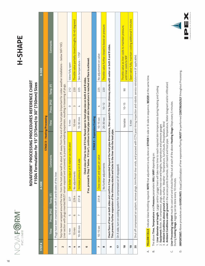
shee
t mus
t be
used
and
and
sho
uld
be fi
lled
out a
t eac
h of
the
abov
e He
atin
g St
age
Step
s ev
ery
5 m
inut
es.
Durin
g Co
olin
g St
age,
logg
ing
can
be d
one
ever
y 10
min
utes
.
D.
IMPO
RTAN
T: A
bove
pro
cedu
res
are
GUID
ELIN
ES; V
isua
l Con
firm
atio
n of
liner
exp
ansi
on/f
larin
g M
UST
be p
erfo
rmed
CON
TIN
UOUS
LY th
roug
hout
Pro
cess
ing.
NOV
AFOR
MTM
PRO
CESS
ING
PROC
EDUR
ES R
EFER
ENCE
CHA
RT
F150
4 Fo
rmul
atio
n fo
r 6” (
150m
m) t
o 12
” (30
0mm
) Siz
esFL
AT
18
STEP
#A-
SIDE
B-SI
DE
STAG
E D
- Hea
ting/
Proc
essi
ng
Tim
e Pr
ess.
(PSI
) Te
mp.
(F)
Com
men
tsTi
me
Pres
s. (P
SI)
Tem
p. (F
)Co
mm
ents
1Pl
ugs
have
bee
n in
sert
ed o
n bo
th A
and
B s
ides
of t
he lin
er.
2Ta
rp h
as b
een
wra
pped
aro
und
the
liner
, fro
m th
e ho
st p
ipe/
wal
l to
abou
t 2ft
away
from
the
end
of th
e ho
st p
ipe
(impo
rtan
t for
cold
er w
eath
er in
stal
latio
ns –
bel
ow 5
0F/1
0C).
Li
ner s
ectio
n w
ith p
lugs
inse
rted
MUS
T re
mai
n ex
pose
d an
d un
cove
red,
to p
reve
nt o
verh
eatin
g/ex
pans
ion,
resu
lting
in lo
osen
ing
of p
lugs
.
35
min
522
7Se
t boi
ler o
utpu
t at A
-sta
tion
as in
dica
ted
5 m
in0
212
Valv
e fu
lly o
pen
410
min
622
9.4
No a
djus
tmen
ts10
min
322
0Th
rott
le v
alve
par
tially
clos
ed (r
ough
ly 3
5-40
deg
rees
)
510
-30
min
723
1.8
Incr
ease
pre
ssur
e on
A s
ide
10-3
0 m
in4
225
Skin
tem
pera
ture
~ 1
75F
6Ch
eck
size
of l
iner
to s
ee if
it h
as fl
ared
ope
n to
hos
t pip
e si
ze o
n bo
th A
and
B s
ides
. If
so,
pro
ceed
to S
tep
7 be
low
. If
it is
n’t,
cont
inue
to h
eat p
ipe
until
ski
n te
mpe
ratu
re is
reac
hed
and
flare
is a
chie
ved.
STAG
E E
- Exp
ansi
on/C
oolin
g
710
-15
sec
723
1.8
Clos
e st
eam
and
ope
n ai
r val
ve10
-15
sec
422
5No
adj
ustm
ent o
n va
lve
8No
furt
her a
djus
tmen
ts20
-30
sec
10-1
222
0Th
rott
le v
alve
furt
her c
lose
d to
boo
st a
ir pr
essu
re
9Ch
eck
flare
of l
iner
on
both
sid
es a
nd co
nfirm
it h
as e
xpan
ded
beyo
nd th
e ho
st p
ipe
dim
ensi
ons,
then
que
nch
the
liner
chim
ney
stac
ks w
ith w
ater
on
both
A a
nd B
sid
es.
This
pre
vent
s fu
rthe
r exp
ansi
on o
f the
chim
ney
stac
ks a
nd lo
cks
in th
e lin
er in
to th
e ho
st p
ipe.
17On
A s
ide,
turn
on
cool
ing
syst
em fo
r com
pres
sed
air (
if eq
uipp
ed).
18Va
riabl
e10
-15
90Th
rott
le v
alve
as
liner
cool
s to
mai
ntai
n pr
essu
re,
until
liner
cool
s to
90F
195
min
Open
val
ve fu
lly, m
aint
ain
cool
ing
addi
tiona
l 5 m
inut
es
20Sh
ut o
ff co
mpr
esse
d ai
r sys
tem
, rem
ove
plug
s, tr
im/f
inis
h lin
er e
nds,
and
pro
ceed
with
CCT
V po
st-li
ning
insp
ectio
n an
d ro
botic
ser
vice
rein
stat
emen
t (if
appl
icabl
e).
NOV
AFOR
MTM
PRO
CESS
ING
PROC
EDUR
ES R
EFER
ENCE
CHA
RT
F150
4 Fo
rmul
atio
n fo
r 15”
(375
mm
) to
30” (
750m
m) S
izes
A.
YELL
OW C
ELLS
Ind
icate
Val
ve th
rott
ling
requ
ired.
NOT
E th
at a
djus
tmen
t is
only
don
e on
EIT
HER
A-si
de o
r B-s
ide
in s
eque
nce,
NEV
ER a
t the
sam
e tim
e.
B.
The
abov
e Ti
me,
Tem
pera
ture
and
Pre
ssur
e pa
ram
eter
s W
ILL
VARY
dep
endi
ng o
n:1.
Lin
er d
iam
eter
and
leng
th:
Larg
er a
nd/o
r Lon
ger l
iner
s w
ill ta
ke m
ore
time
to re
ach
requ
ired
skin
tem
pera
ture
s du
ring
Heat
ing
and
Cool
ing
2. E
quip
men
t: Bo
iler,
Air c
ompr
esso
r, pl
ugs,
ste
am h
ose
size
and
leng
ths,
tem
pera
ture
and
pre
ssur
e ga
uges
3. A
mbi
ent C
ondi
tions
abo
ve g
roun
d at
the
surfa
ce: W
eath
er –
Tem
pera
ture
, Sun
/Clo
uds,
Pre
cipita
tion,
Win
d4.
Am
bien
t Con
ditio
ns u
nder
gro
und
in th
e ac
cess
poi
nts
(man
hole
, cat
ch b
asin
) and
hos
t pip
e: T
empe
ratu
re, W
ater
(sta
gnan
t and
/or i
nfilt
ratio
n)
C.
Line
r Pro
cess
ing
Log
shee
t mus
t be
used
and
and
sho
uld
be fi
lled
out a
t eac
h of
the
abov
e He
atin
g St
age
Step
s ev
ery
5 m
inut
es.
Durin
g Co
olin
g St
age,
logg
ing
can
be d
one
ever
y 10
min
utes
.
D.
IMPO
RTAN
T: A
bove
pro
cedu
res
are
GUID
ELIN
ES; V
isua
l Con
firm
atio
n of
liner
exp
ansi
on/f
larin
g M
UST
be p
erfo
rmed
CON
TIN
UOUS
LY th
roug
hout
Pro
cess
ing.
H-SH
APE

19
Date: Reel Name and #: USMH: DSMH:
Diameter: Length: Liner SDR: # of Services:
Agency: Contractor Job #: Host Line ID #:
I certify this record sheet to be true and accurate:
Signature of Foreman
Boiler Press.Output:
PROCESSING/EXPANSION/COOLING LOGPRE HEAT LOG
PVC Liner Process Record
Boiler Temp.Output:
Time Press. (PSI) Temp. (F) Side Comments
Time Temp. (F)

Products are manufactured by IPEX Inc. and distributed in the United States by IPEX USA LLC. NovaFormTM is a trademark of IPEX Branding Inc.
MNMNNFIP170414