installation manual - free · this installation manual describes the procedures for installing and...
TRANSCRIPT
INSTALLATION MANUAL
EKHWSU150B3V3EKHWSU200B3V3EKHWSU300B3V3
EKUHWB
EKUHW2WB
Domestic hot water tank with option kitfor air to water heat pump system
Installation manual
1
EKUHWB + EKUHW2WB + EKHWSU150-300B3V3Domestic hot water tank with option kit for air to water heat pump system
4PW44439-1
C
ONTENTS
Page
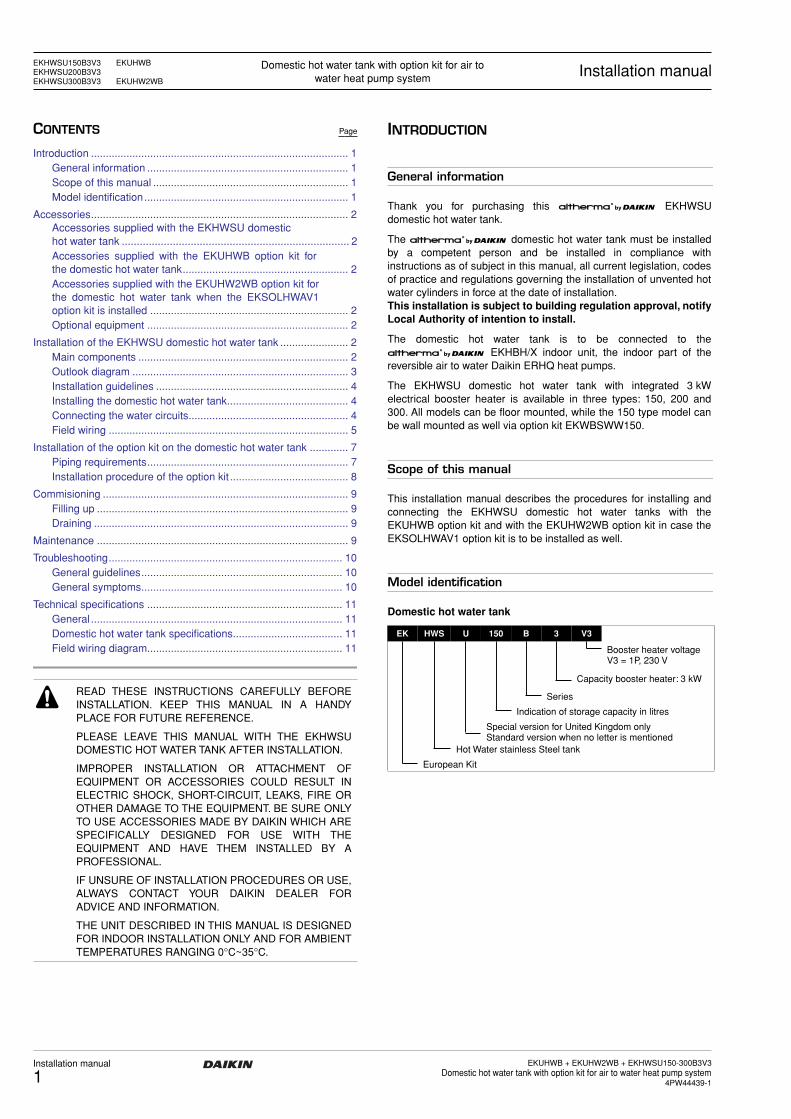
Introduction ....................................................................................... 1General information .................................................................... 1Scope of this manual .................................................................. 1Model identification..................................................................... 1
Accessories....................................................................................... 2Accessories supplied with the EKHWSU domestichot water tank ............................................................................ 2Accessories supplied with the EKUHWB option kit forthe domestic hot water tank........................................................ 2Accessories supplied with the EKUHW2WB option kit forthe domestic hot water tank when the EKSOLHWAV1option kit is installed ................................................................... 2Optional equipment .................................................................... 2
Installation of the EKHWSU domestic hot water tank ....................... 2Main components ....................................................................... 2Outlook diagram ......................................................................... 3Installation guidelines ................................................................. 4Installing the domestic hot water tank......................................... 4Connecting the water circuits...................................................... 4Field wiring ................................................................................. 5
Installation of the option kit on the domestic hot water tank ............. 7Piping requirements.................................................................... 7Installation procedure of the option kit ........................................ 8
Commisioning ................................................................................... 9Filling up ..................................................................................... 9Draining ...................................................................................... 9
Maintenance ..................................................................................... 9
Troubleshooting............................................................................... 10General guidelines.................................................................... 10General symptoms.................................................................... 10
Technical specifications .................................................................. 11General ..................................................................................... 11Domestic hot water tank specifications..................................... 11Field wiring diagram.................................................................. 11
I
NTRODUCTION
General information
Thank you for purchasing this
AD
EKHWSUdomestic hot water tank.
The
AD
domestic hot water tank must be installedby a competent person and be installed in compliance withinstructions as of subject in this manual, all current legislation, codesof practice and regulations governing the installation of unvented hotwater cylinders in force at the date of installation.
This installation is subject to building regulation approval, notifyLocal Authority of intention to install.
The domestic hot water tank is to be connected to the
AD
EKHBH/X indoor unit, the indoor part of thereversible air to water Daikin ERHQ heat pumps.
The EKHWSU domestic hot water tank with integrated 3 kWelectrical booster heater is available in three types: 150, 200 and300. All models can be floor mounted, while the 150 type model canbe wall mounted as well via option kit EKWBSWW150.
Scope of this manual
This installation manual describes the procedures for installing andconnecting the EKHWSU domestic hot water tanks with theEKUHWB option kit and with the EKUHW2WB option kit in case theEKSOLHWAV1 option kit is to be installed as well.
Model identification
Domestic hot water tank
EKHWSU150B3V3 EKUHWBEKHWSU200B3V3EKHWSU300B3V3 EKUHW2WB
Domestic hot water tank with option kit for air to water heat pump system
Installation manual
READ THESE INSTRUCTIONS CAREFULLY BEFOREINSTALLATION. KEEP THIS MANUAL IN A HANDYPLACE FOR FUTURE REFERENCE.
PLEASE LEAVE THIS MANUAL WITH THE EKHWSUDOMESTIC HOT WATER TANK AFTER INSTALLATION.
IMPROPER INSTALLATION OR ATTACHMENT OFEQUIPMENT OR ACCESSORIES COULD RESULT INELECTRIC SHOCK, SHORT-CIRCUIT, LEAKS, FIRE OROTHER DAMAGE TO THE EQUIPMENT. BE SURE ONLYTO USE ACCESSORIES MADE BY DAIKIN WHICH ARESPECIFICALLY DESIGNED FOR USE WITH THEEQUIPMENT AND HAVE THEM INSTALLED BY APROFESSIONAL.
IF UNSURE OF INSTALLATION PROCEDURES OR USE,ALWAYS CONTACT YOUR DAIKIN DEALER FORADVICE AND INFORMATION.
THE UNIT DESCRIBED IN THIS MANUAL IS DESIGNEDFOR INDOOR INSTALLATION ONLY AND FOR AMBIENTTEMPERATURES RANGING 0°C~35°C.
EK HWS U 150 B 3 V3
Booster heater voltageV3 = 1P, 230 V
Capacity booster heater: 3 kW
Series
Indication of storage capacity in litres
Special version for United Kingdom onlyStandard version when no letter is mentioned
Hot Water stainless Steel tank
European Kit

EKUHWB + EKUHW2WB + EKHWSU150-300B3V3Domestic hot water tank with option kit for air to water heat pump system4PW44439-1
Installation manual
2
A
CCESSORIES
Accessories supplied with the EKHWSU domestic hot
water tank
Accessories supplied with the EKUHWB option kit for
the domestic hot water tank
Accessories supplied with the EKUHW2WB option kit for the domestic hot water tank when the
EKSOLHWAV1 option kit is installed
Optional equipment
EKWBSWW150: kit, including a wall bracket for a domestic hot watertank of 150 litres.
I
NSTALLATION
OF
THE
EKHWSU
DOMESTIC
HOT
WATER
TANK
Main components
1
Thermistor + connection wire (12 m)
2
Contactor - fuse assembly
3
Contactor fixing screw
4
Tapping screw
5
3-way valve + motor
6
Installation manual
1
Pressure reducing valve
2
Expansion relief valve
3
Blind stop + 2 plastic screw-on closing caps for pressure reducing valve
4
T-piece 1/2” Female BSP x 15 mm x 15 mm
5
Expansion vessel of 18 litres
6
Tundish
7
Elbow/Drain valve 22 mm x 3/4” Male BSP
8
Adaptor 22 mm x 3/4” Female BSP
9
T-piece 22 mm x 22 mm x 22 mm
10
Instruction sheet
1
Solenoid 2-way valve 3/4” Female BSP x 3/4” Female BSP
2
Connection nipple 3/4” Male BSP
3
PG nipple and nut
1x 2x 1x1x1x 4x1 3 5 62 4
1x
1x 1x
1x1x
1x 1x
1
1x
2 3 4 5
76 10
1x
8
1x
9
1x
1
2x2
1x3
■
The total
AD
system (indoor unitand outdoor unit) is designed for combination with an
AD
domestic hot water tank. In caseanother tank or a spare part other than native Daikinis being used in combination with the
AD
indoor unit, Daikin cannotguarantee neither good operation nor reliability of thesystem. For those reasons Daikin cannot givewarranty of the system in such case.
■
For safety reasons, it is not allowed to add ethyleneglycol to the water circuit. Adding ethylene glycolmight lead to contamination of the domestic water if aleakage would occur in the heat exchanger coil.
■
Only this tank can be used in combination with thesolar kit option.
■
Domestic water quality must be according to ENdirective 98/83 EC.
■
It is important that the storage capacity of thedomestic water tank meets normal daily fluctuationsin consumption of hot water without any fall of thewater outlet temperature during use.
■
Immediately after installation, the domestic hot watertank must be flushed with fresh water. This proceduremust be repeated at least once a day the first 5consecutive days after installation.
1
Hot water connection
2
Temperature and pressure relief valve
3
Electrical box
4
7
10
11
8
5
6
R
F
9
H
1
2
15
14
13
12
3
C
Installation manual
3
EKUHWB + EKUHW2WB + EKHWSU150-300B3V3Domestic hot water tank with option kit for air to water heat pump system
4PW44439-1
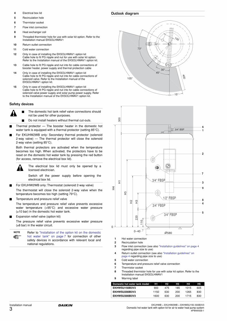
Safety devices
■
Thermal protector — The booster heater in the domestic hotwater tank is equipped with a thermal protector (setting 85°C).
■
For EKUHW2WB only: Secondary thermal protector (solenoid2-way valve) — The thermal protector will close the solenoid2-way valve (setting 85°C).
Both thermal protectors are activated when the temperaturebecomes too high. When activated, the protectors have to bereset on the domestic hot water tank by pressing the red button(for access, remove the electrical box lid).
■
For EKUHW2WB only: Thermostat (solenoid 2-way valve)
The thermostat will close the solenoid 2-way valve when thetemperature becomes too high (setting 79°C).
■
Temperature and pressure relief valve
The temperature and pressure relief valve prevents excessivewater temperature (>95°C) and excessive water pressure(
≥
10 bar) in the domestic hot water tank.
■
Expansion relief valve (option kit)
The pressure relief valve prevents excessive water pressure(
≥
8 bar) in the water circuit.
Outlook diagram
4
Electrical box lid
5
Recirculation hole
6
Thermistor socket
7
Flow inlet connection
8
Heat exchanger coil
9
Threaded thermistor hole for use with solar kit option. Refer to the Installation manual EKSOLHWAV1
10
Return outlet connection
11
Cold water connection
12
Only in case of installing the EKSOLHWAV1 option kitCable hole to fit PG nipple and nut for use with solar kit option. Refer to the Installation manual of the EKSOLHWAV1 option kit.
13
Cable hole to fit PG nipple and nut into for cable connections of booster heater, power supply and thermal protection cable
14
Only in case of installing the EKSOLHWAV1 option kitCable hole to fit PG nipple and nut into for cable connections of solenoid valve. Refer to the Installation manual of the EKSOLHWAV1 option kit.
15
Only in case of installing the EKSOLHWAV1 option kitCable hole to fit PG nipple and nut into for cable connections of solenoid valve power supply and solar pump power supply. Refer to the Installation manual of the EKSOLHWAV1 option kit.
■
The domestic hot tank relief valve connections shouldnot be used for other purposes.
■
Do not install heaters without thermal cut-outs.
The electrical box lid must only be opened by alicensed electrician.
Switch off the power supply before opening theelectrical box lid.
NOTE
Refer to "Installation of the option kit on the domestichot water tank" on page 7 for connection of othersafety devices in accordance with relevant local andnational regulations.
1
Hot water connection
2
Recirculation hole
3
Flow inlet connection (see also "Installation guidelines" on page 4 regarding pipe size to use)
4
Return outlet connection (see also "Installation guidelines" on page 4 regarding pipe size to use)
5
Cold water connection
6
Temperature and pressure relief valve connection
7
Thermistor socket
8
Threaded thermistor hole for use with solar kit option. Refer to the Installation manual EKSOLHWAV1
9
Warning label
Domestic hot water tank model H1 H2 H3 H4 H5
EKHWSU150B3V3
900 475 185 1015 605
EKHWSU200B3V3
1150 630 200 1265 830
EKHWSU300B3V3
1600 630 200 1715 830
105°
45°30°
73°
100
15°
400
300

EKUHWB + EKUHW2WB + EKHWSU150-300B3V3Domestic hot water tank with option kit for air to water heat pump system4PW44439-1
Installation manual
4
Installation guidelines
Keep in mind the following guidelines when installing the domestichot water tank:
■
The installation location is frost-free.
■
Make sure to make the piping in size 1" or more (and reduce to3/4" at the inlet of the tank) as to have sufficient water volume inthe piping between indoor unit and domestic hot water tank.
■
Locate the domestic hot water tank in a suitable position tofacilitate easy maintenance; remember access is required to theelectrical box. Refer to the grey zones in the outlook diagram.
■
The domestic hot water tank modelEKHWSU150B3V3 can be floor or wallmounted. In case of wall mounting, wallmounting kit EKWBSWW150 is required(separate ordering).
■
If installing an EKHWSU* domestic hot water tank, installing theoption kit EKUHWB is obligatory. Refer to the UK BuildingRegulation G3.
■
If installing the kit EKSOLHWAV1, installing the option kitEKUHW2WB is obligatory.
■
Take care that in the event of a leak, water cannot cause anydamage to the installation space and surroundings
Installing the domestic hot water tank
1
Check if all domestic hot water tank accessories (see"Accessories" on page 2) are enclosed.
2
When floor mounting, place the domestic hot water tank on alevel surface. When wall mounting (only for EKHWSU150B3V3model), make sure the wall is sturdy. In both cases, make surethe tank is mounted level.
3
Apply thermal paste to the thermistor and insert the thermistor asdeep as possible in the thermistor socket. Fix using the nut provided.
Connecting the water circuits
Refer to the chapter “Typical application examples” described in theinstallation manual delivered with the indoor unit for details onconnecting the water circuits and the motorised 3-way valve.
Connecting the 3-way valve
1
Refer to the figure below before making the connection.
2
Installation position.
It is advised to connect the 3-way valve as close as possible tothe indoor unit. It can be installed according the following fourconfigurations.
3
Unpack the 3-way valve body and 3-way valve motor.
Verify that following accessories are provided with the motor.
4
Install the 3-way valve body in the pipework.
• Make sure the shaft will be positioned in such a way that themotor can be mounted and replaced.
• When installing the valve according to figure C or figure D,remove the indication plate and turn it upside down, makingsure the scale "0 to 10" is located on the lower left bottom ofthe valve.
• Put the sleeve on the valve and turn the valve to the middleposition (marked as "5") of the scale plate.Check that the valve is positioned as in the figure below. Itshould be blocking the outlet connection to the domestic hotwater for 50% and the outlet connection to the room heatingalso for 50%.
figure A figure B
9382
129
20
44
37
4
65
1
2
3
1
3
2
figure C figure D
1
From
AD
indoor unit
2
To domestic hot water tank
3
To room heating
1
Sleeve
2
Screw
3
Central screw
4
Red/blue scale
5
Cover
6
Indication plate
7 Valve motor cover
Installation accordingfigure A and figure B
Installation accordingfigure C and figure D
If the valve is not positioned in this way before mountingthe motor, the valve will give way to both domestic waterand room heating during operation.
1
2
3
1
3
2
1 2 65 4 3 7

Installation manual
5EKUHWB + EKUHW2WB + EKHWSU150-300B3V3
Domestic hot water tank with option kit for air to water heat pump system4PW44439-1
5 When installing according to figure B or figure C, open the valvemotor cover by loosening the 4 screws and change the jumperas to change the rotation direction of the valve.
By default the jumper is factory set to apply for installationaccording to figure A and figure D.
6 Fit screw 2 (see step 3) in the lower right hand corner of thevalve cover plate.
7 Push the motor on the motor sleeve.
Make sure not to rotate the sleeve during this action, as tomaintain the valve position as set during step 4.
8 Put the red/blue scale on the valve as shown below.
The red arrow will point to the red zone when the valve is indomestic water heating mode and will point to the blue zonewhen the valve is in room heating mode.
9 Make the wiring in the indoor unit according to following figure:
Refer also to the drawing on page 6.
Refer to "Installation of the option kit on the domestic hot water tank"on page 7 for details on installation in accordance with relevant localand national regulations.
Field wiring
Also refer to "Field wiring diagram" on page 11.
Power circuit and cable requirements
For cable requirements and specifications, refer to "Field wiring" inthe indoor unit installation manual supplied with the EKHBH/X unit.
Thermistor cable
The distance between the thermistor cable and power supply cablemust always be at least 5 cm to prevent electromagnetic interferenceon the thermistor cable.
Procedure
Connections to be made in the domestic hot water tank electrical box
1 Prior to upwiring Make sure to ensure strain relief of the power cable by correctlymounting the PG nipple and PG nut (delivered with the tank).
Installation according figure A and figure D
Installation accordingfigure B and figure C
Installation accordingfigure A and figure B
Installation accordingfigure C and figure D
Installation accordingfigure A and figure D
Installation accordingfigure B and figure C
8 9 10
3-way valve
BLK
BLU
BR
N
■ A main switch or other means for disconnection,having a contact separation in all poles, must beincorporated in the fixed wiring in accordance withrelevant local and national legislation.
■ All field wiring and components must be installed by alicensed electrician and must comply with relevantEuropean and national regulations.
■ The field wiring must be carried out in accordancewith the wiring diagram sticker supplied with the unitand the instructions given below.
■ The domestic hot water tank must be earthed via theindoor unit.
■ Be sure to use a dedicated power circuit. Never use apower circuit shared by another appliance.
■ Use one and same dedicated power supply for theoutdoor unit, indoor unit, backup heater and domestichot water tank.
NOTE Select the power cable in accordance with relevantlocal and national regulations.
Switch off the power supply before making anyconnections.
Make sure all field wiring is insulated from the surface ofthe inspection hole or can resist temperatures to 90°C.
1x

EKUHWB + EKUHW2WB + EKHWSU150-300B3V3Domestic hot water tank with option kit for air to water heat pump system4PW44439-1
Installation manual
6
2 Booster heater power supplyConnect the booster heater powersupply and thermal protectioncable as shown in wiring diagramsticker on the inside of the switchbox lid.
3 Solenoid valve power supply
Connect the solenoid valve powersupply cable as shown in the fol-lowing diagram sticker on theinside of the switch box lid.
4 Solenoid valve
Connect the solenoid valve asshown in the following diagramsticker on the inside of the switchbox lid.
Connections to be made in the indoor unit switch box
5 Mount the prewired contactor (K3M), circuit breaker (F2B) andterminal blocks (X3M, X4M). The contactor and terminal blocksshould be fixed with the 3x 2 screws supplied.
6 Plug the connector connected to the contactor K3M in thesocket X13A on the PCB.
7 Plug the thermistor cable connector in the socket X9A on thePCB.
8 Connect the prewired earth wires of the terminal block X3M andX4M to the earthing screw.
9 Connect the booster heater power supply and thermal protectioncable (field supply) to terminal X4M earth, 1, 2, and X2M 13, 14.
10 Connect the booster heater power supply cable to the terminalblock X3M.
11 Connect the solenoid valve power supply cable to terminal blockX7M as shown on wiring diagram B in paragraph "Connectionsto be made in the domestic hot water tank electrical box" onpage 5.
12 Fix the cables to the cable tie mountings with cable ties toensure strain relief.
13 Set DIP switch SS2-2 on the PCB to ON.
14 When routing out cables, make sure that these do not obstructmounting of the indoor unit cover.
Note: only relevant field wiring is shown.6
A4P
K6M
F2B
3MK7M
21
X4M
4a
OPTIONAL
X2M
2120Q2L3-way valve2-way valve
12114
thermostat
21 3 5 6 7 8 9 10 13 19
thermal fuse
14 15 16 17 18SOLAR PUMP
NLL2L1
X3M (230V)
F1B
TR1
TR1
A1P
A1P
X2M
X1M
K5MK2M
K1M
K1M
K2MK5M
K4M
1 2 3 L1 L2 L3 N
15a
K3M
X9A
X13A
1 2 4
2
3
X4M X2M
>50 mm
3 wayvalve
BLK
BR
N
BLU
X4M
X3M
Installation manual
7EKUHWB + EKUHW2WB + EKHWSU150-300B3V3
Domestic hot water tank with option kit for air to water heat pump system4PW44439-1
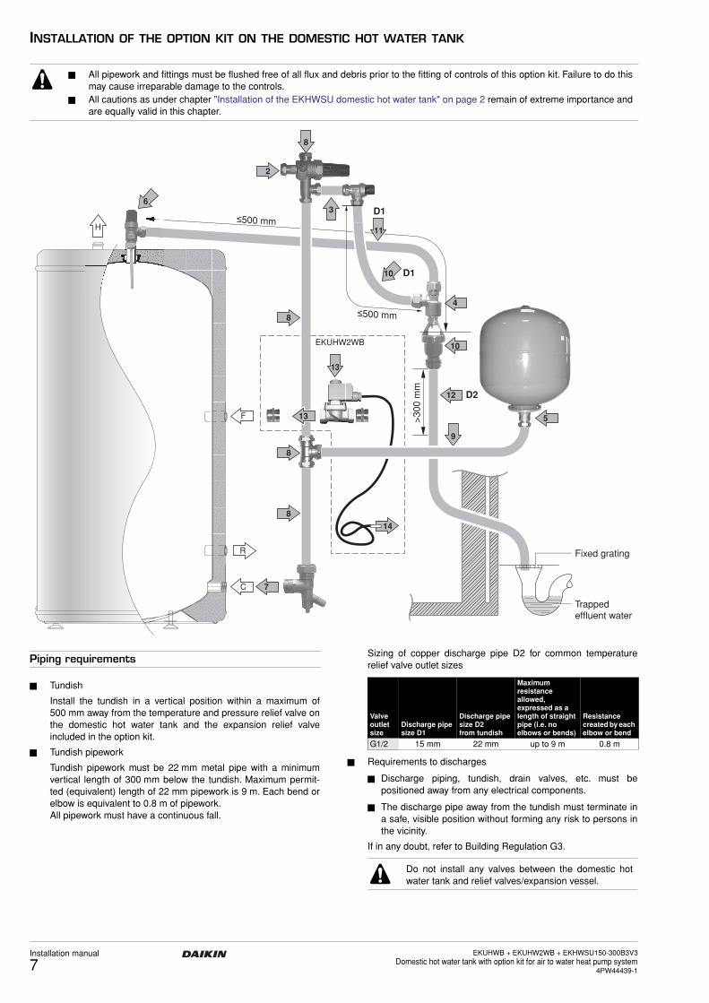
INSTALLATION OF THE OPTION KIT ON THE DOMESTIC HOT WATER TANK
Piping requirements
■ Tundish
Install the tundish in a vertical position within a maximum of500 mm away from the temperature and pressure relief valve onthe domestic hot water tank and the expansion relief valveincluded in the option kit.
■ Tundish pipework
Tundish pipework must be 22 mm metal pipe with a minimumvertical length of 300 mm below the tundish. Maximum permit-ted (equivalent) length of 22 mm pipework is 9 m. Each bend orelbow is equivalent to 0.8 m of pipework.All pipework must have a continuous fall.
Sizing of copper discharge pipe D2 for common temperaturerelief valve outlet sizes
■ Requirements to discharges
■ Discharge piping, tundish, drain valves, etc. must bepositioned away from any electrical components.
■ The discharge pipe away from the tundish must terminate ina safe, visible position without forming any risk to persons inthe vicinity.
If in any doubt, refer to Building Regulation G3.
■ All pipework and fittings must be flushed free of all flux and debris prior to the fitting of controls of this option kit. Failure to do thismay cause irreparable damage to the controls.
■ All cautions as under chapter "Installation of the EKHWSU domestic hot water tank" on page 2 remain of extreme importance andare equally valid in this chapter.
H
C
R
F
7
≤500 mm
>30
0 m
m
D1
D1
D2
Fixed grating
Trappedeffluent water
10
10
11
8
8
8
2
8
3
12
9
13
14
513
≤500 mm4
6
EKUHW2WB
Valve outlet size
Discharge pipe size D1
Discharge pipe size D2 from tundish
Maximum resistance allowed, expressed as a length of straight pipe (i.e. no elbows or bends)
Resistance created by each elbow or bend
G1/2 15 mm 22 mm up to 9 m 0.8 m
Do not install any valves between the domestic hotwater tank and relief valves/expansion vessel.
EKUHWB + EKUHW2WB + EKHWSU150-300B3V3Domestic hot water tank with option kit for air to water heat pump system4PW44439-1
Installation manual
8
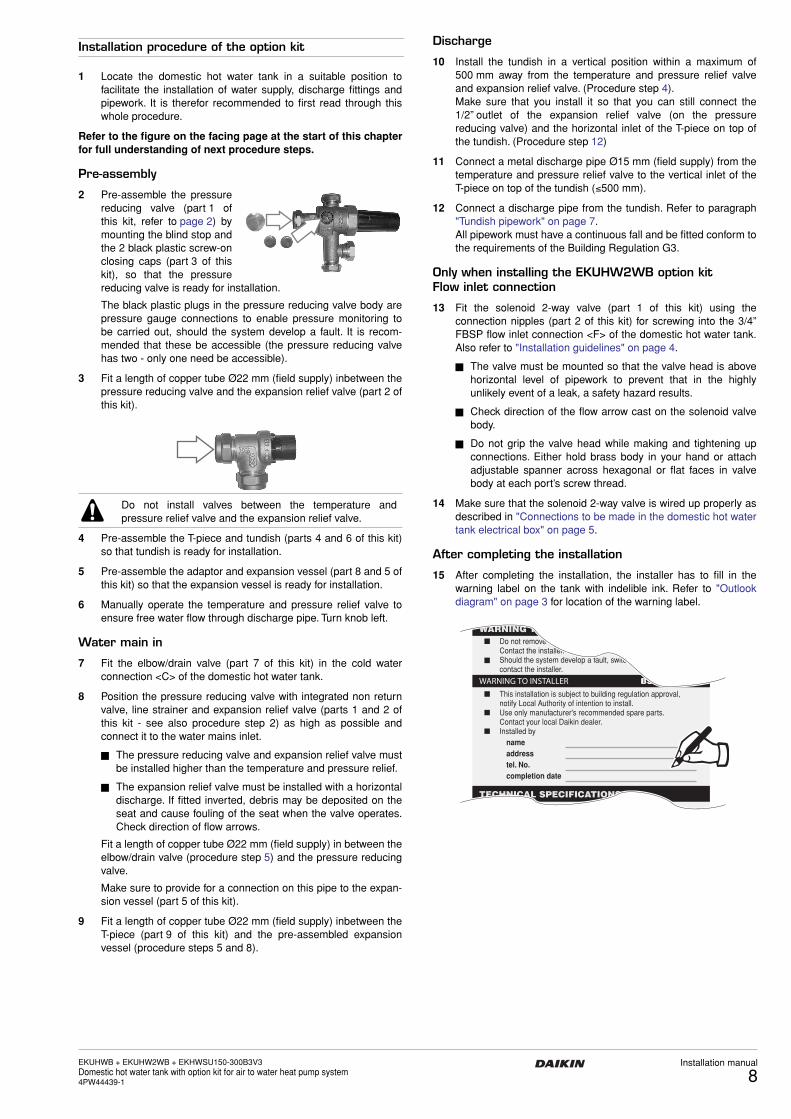
Installation procedure of the option kit
1 Locate the domestic hot water tank in a suitable position tofacilitate the installation of water supply, discharge fittings andpipework. It is therefor recommended to first read through thiswhole procedure.
Refer to the figure on the facing page at the start of this chapterfor full understanding of next procedure steps.
Pre-assembly
2 Pre-assemble the pressurereducing valve (part 1 ofthis kit, refer to page 2) bymounting the blind stop andthe 2 black plastic screw-onclosing caps (part 3 of thiskit), so that the pressurereducing valve is ready for installation.
The black plastic plugs in the pressure reducing valve body arepressure gauge connections to enable pressure monitoring tobe carried out, should the system develop a fault. It is recom-mended that these be accessible (the pressure reducing valvehas two - only one need be accessible).
3 Fit a length of copper tube Ø22 mm (field supply) inbetween thepressure reducing valve and the expansion relief valve (part 2 ofthis kit).
4 Pre-assemble the T-piece and tundish (parts 4 and 6 of this kit)so that tundish is ready for installation.
5 Pre-assemble the adaptor and expansion vessel (part 8 and 5 ofthis kit) so that the expansion vessel is ready for installation.
6 Manually operate the temperature and pressure relief valve toensure free water flow through discharge pipe. Turn knob left.
Water main in
7 Fit the elbow/drain valve (part 7 of this kit) in the cold waterconnection <C> of the domestic hot water tank.
8 Position the pressure reducing valve with integrated non returnvalve, line strainer and expansion relief valve (parts 1 and 2 ofthis kit - see also procedure step 2) as high as possible andconnect it to the water mains inlet.
■ The pressure reducing valve and expansion relief valve mustbe installed higher than the temperature and pressure relief.
■ The expansion relief valve must be installed with a horizontaldischarge. If fitted inverted, debris may be deposited on theseat and cause fouling of the seat when the valve operates.Check direction of flow arrows.
Fit a length of copper tube Ø22 mm (field supply) in between theelbow/drain valve (procedure step 5) and the pressure reducingvalve.
Make sure to provide for a connection on this pipe to the expan-sion vessel (part 5 of this kit).
9 Fit a length of copper tube Ø22 mm (field supply) inbetween theT-piece (part 9 of this kit) and the pre-assembled expansionvessel (procedure steps 5 and 8).
Discharge
10 Install the tundish in a vertical position within a maximum of500 mm away from the temperature and pressure relief valveand expansion relief valve. (Procedure step 4).Make sure that you install it so that you can still connect the1/2” outlet of the expansion relief valve (on the pressurereducing valve) and the horizontal inlet of the T-piece on top ofthe tundish. (Procedure step 12)
11 Connect a metal discharge pipe Ø15 mm (field supply) from thetemperature and pressure relief valve to the vertical inlet of theT-piece on top of the tundish (≤500 mm).
12 Connect a discharge pipe from the tundish. Refer to paragraph"Tundish pipework" on page 7.All pipework must have a continuous fall and be fitted conform tothe requirements of the Building Regulation G3.
Only when installing the EKUHW2WB option kitFlow inlet connection
13 Fit the solenoid 2-way valve (part 1 of this kit) using theconnection nipples (part 2 of this kit) for screwing into the 3/4”FBSP flow inlet connection <F> of the domestic hot water tank.Also refer to "Installation guidelines" on page 4.
■ The valve must be mounted so that the valve head is abovehorizontal level of pipework to prevent that in the highlyunlikely event of a leak, a safety hazard results.
■ Check direction of the flow arrow cast on the solenoid valvebody.
■ Do not grip the valve head while making and tightening upconnections. Either hold brass body in your hand or attachadjustable spanner across hexagonal or flat faces in valvebody at each port’s screw thread.
14 Make sure that the solenoid 2-way valve is wired up properly asdescribed in "Connections to be made in the domestic hot watertank electrical box" on page 5.
After completing the installation
15 After completing the installation, the installer has to fill in thewarning label on the tank with indelible ink. Refer to "Outlookdiagram" on page 3 for location of the warning label.
Do not install valves between the temperature andpressure relief valve and the expansion relief valve.
Do not removeContact the installer.Should the system develop a fault, switccontact the installer.
This installation is subject to building regulation approval,notify Local Authority of intention to install.Use only manufacturer's recommended spare parts.Contact your local Daikin dealer.Installed by
nameaddresstel. No.completion date

Installation manual
9EKUHWB + EKUHW2WB + EKHWSU150-300B3V3
Domestic hot water tank with option kit for air to water heat pump system4PW44439-1
COMMISIONING
Filling up
Follow the next steps to fill up the tank:
1 Switch off the power supply.
2 Open each hot water tap in turn to expel air from the systempipe work.
3 Open the cold water supply valve.
4 Check for leaks.
5 Close all water taps if all air is expelled.
6 Manually operate the temperature and pressure relief valve toensure free water flow through the discharge pipe (turn knobleft). Refer to "Main components" on page 2 for location of thetemperature and pressure relief valve.
Draining
Follow the next steps to drain the tank:
1 Switch off the power supply.
2 Turn off the cold water supply valve.
3 Open the hot water taps.
4 Open the drain valve.
MAINTENANCE
In order to ensure optimal availability of the unit, a number of checksand inspections on the unit and the field wiring have to be carried outat regular intervals.
The described checks must be executed at least once a year.
1 Domestic hot water tank booster heater
It is advisable to remove lime buildup on the booster heater toextend its life span, especially in regions with hard water. To doso, drain the domestic hot water tank, remove the booster heaterfrom the domestic hot water tank and immerse in a bucket (orsimilar) with lime-removing product for 24 hours.
2 Temperature and pressure relief valve
Check for correct operation of the temperature and pressurerelief valve. Manually operate the temperature and pressurerelief valve to ensure free water flow through discharge pipe.Turn knob left.
3 Pressure reducing valve with integrated non return valve andline strainer
Depending on local water conditions, annual inspection of theintegral line strainer, pressure reducing valve cartridge and seat-ing may be necessary.- Unscrew the retaining nut of the valve. The complete
operating mechanism, including the strainer can be removed.- Clean the filter mesh and cartridge under running water.- Replace cartridge, ensuring that strainer is correctly located
and reassemble the unit.
4 Expansion relief valve
Check for correct operation of the expansion relief valve. Manu-ally operate the expansion relief valve to ensure free water flowthrough discharge pipe. Turn knob left.
Depending on local water conditions, annual inspection of theexpansion relief valve cartridge and seating may be necessary.- Unscrew the expansion relief headwork from valve body.- Clean valve seat face and seating - do not scratch or damage
either seat face or seating.- Refit in reverse order. Do not over tighten.
5 Indoor unit switch box
■ Carry out a thorough visual inspection of the switch box andlook for obvious defects such as loose connections ordefective wiring.
■ Check for correct operation of contactor K3M by use of anohmmeter. All contacts of this contactor must be in openposition.
■ Before carrying out any maintenance or repair activity,always switch off the circuit breaker on the supplypanel, remove the fuses or open the protectiondevices of the unit.
■ Make sure that before starting any maintenance orrepair activity, also the power supply to the outdoorunit is switched off.

EKUHWB + EKUHW2WB + EKHWSU150-300B3V3Domestic hot water tank with option kit for air to water heat pump system4PW44439-1
Installation manual
10
TROUBLESHOOTING
This section provides useful information for diagnosing and correct-ing certain troubles which may occur in the unit.
General guidelines
Before starting the trouble shooting procedure, carry out a thoroughvisual inspection of the unit and look for obvious defects such asloose connections or defective wiring.
Before contacting your local dealer, read this chapter carefully, it willsave you time and money.
When a safety device was activated, stop the unit and find out whythe safety device was activated before resetting it. Under no circum-stances safety devices may be bridged or changed to a value otherthan the factory setting. If the cause of the problem cannot be found,call your local Daikin dealer
General symptoms
Symptom 1: No water flow from hot taps
Symptom 2: Water from hot taps is cold
Symptom 3: Intermittent water discharge
Symptom 4: Continuous water discharge
When carrying out an inspection on the supply panel or onthe switch box of the unit, always make sure that the circuitbreaker of the unit is switched off.
POSSIBLE CAUSES CORRECTIVE ACTION
The main water supply is off. Check that all shut off valves of the water circuit are completely open.
The strainer is blocked. Turn off the water supply, remove and clean the strainer (see "Pressure reducing valve with integrated non return valve and line strainer" on page 9 on how to do this).
The cold water inlet pressure reducing valve is not fitted properly.
Check and refit as required (see "Pressure reducing valve with integrated non return valve and line strainer" on page 9 on how to do this).
POSSIBLE CAUSES CORRECTIVE ACTION
The thermal cut-out(s) has/have operated
Check and reset button(s).
The indoor unit (EKHBH/X) is not operating.
Check the indoor unit (EKHBH/X) operation. Refer to the manual delivered with the indoor unit.If any faults are suspected, contact your local Daikin dealer.
The solenoid 2-way valve is not operating correctly (only when option kit EKUHW2WB is installed).
Check the wiring, F2U and the plumbing connections to the solenoid 2-way valve.
Check the setting of the thermostat (79°C).
POSSIBLE CAUSES CORRECTIVE ACTION
Thermal control failure (water will be hot).
Switch off power to the indoor unit.When discharge has stopped, check the thermal controls and replace if faulty.Contact your local Daikin dealer.
The expansion vessel is broken. Replace the expansion vessel.
POSSIBLE CAUSES CORRECTIVE ACTION
Cold water inlet pressure. Check the pressure reducing valve. Replace the pressure reducing valve if the measured pressure is >2.1 bar.
Temperature and pressure relief valve.
Check and reset button.
The expansion relief valve is not functioning properly.
Check for correct operation of the pressure relief valve by turning the red knob on the valve counter clockwise:• If you do not hear a clacking
sound, contact your local Daikin dealer.
• In case the water keeps running out of the unit, close both the water inlet and outlet shut-off valves first and then contact your local Daikin dealer.

Installation manual
11EKUHWB + EKUHW2WB + EKHWSU150-300B3V3
Domestic hot water tank with option kit for air to water heat pump system4PW44439-1
TECHNICAL SPECIFICATIONS
General
Domestic hot water tank specifications
Field wiring diagram
E4H ...............Booster heater
F2B................Fuse booster heater
F2U................Fuse 5 A/250 V
K3M...............Contactor booster heater
L ....................Life
N....................Neutral
Q2T ...............Thermostat domestic hot water tank
Q2L................Thermal protector domestic hot water tank
Q3L................Thermal protector booster heater
Y1S................Solenoid valve
X1M...............Terminal block
X5M~X7M .....Terminal block
.................Protective earth
..........Field wiring
Heating/cooling models (EKHBX) Heating only models (EKHBH)
Operation range - air side• domestic hot water by heat pump –20~+35°C(a) –20~+35°C(a)
(a) For EKHB(H/X)008*: down to –20°C and up to +43°C by booster heater
EKHWSU150B3V3 EKHWSU200B3V3 EKHWSU300B3V3
• Storage capacity 150 l 200 l 285 l• Overall dimensions (Ø x H) 580 x 1015 mm 580 x 1265 mm 580 x 1715 mm• Booster heater - power supply 230 V 50 Hz 1P 230 V 50 Hz 1P 230 V 50 Hz 1P
- running current 13 A 13 A 13 A- capacity 3 kW 3 kW 3 kW
• Operating pressure 2.1 bar 2.1 bar 2.1 bar• Maximum primary working pressure
(heating side) 2.5 bar 2.5 bar 2.5 bar
• Expansion vessel pre-charge pressure 2.5 bar 2.5 bar 2.5 bar• Preset opening pressure of expansion
relief valve 8 bar 8 bar 8 bar
• Preset opening temperature of temperature and pressure relief valve 90~95°C 90~95°C 90~95°C
• Set opening pressure of temperature and pressure relief valve 10 bar 10 bar 10 bar
• Connections 3/4” FBSP(a) 3/4” FBSP(a) 3/4” FBSP(a)
• Weight - empty 38 kg 46 kg 60 kg- when full 188 kg 246 kg 345 kg
• Mounting Wall or floor Floor Floor• Supply temperature time(b) 1 hr 15 min 1 hr 41 min 2 hr 26 min• Maximum water supply pressure 8 bar 8 bar 8 bar• Re-heat time(c) 1 hr 5 min 1 hr 29 min 2 hr 8 min
(a) FBSP = Female British Standard Pipe(b) The time it takes to increase the temperature from 15°C to 60°C(c) The time it takes to increase 70% of the contents of the vessel back up to 60°C
Q2T
Q2L
X5M
SR
NL
T
VU W
13 14 1 2 X4MX2M
K3M
X6M
Q3L
Q2L E4H
F2UX7M
F2B
3
43
4
domestic hot water tank electrical box
solenoid valve Y1S
EKUHW2WB
indoor unitswitch box2
12
1
A2
A1

NOTES NOTES

4PW44439-1
Cop
yrig
ht ©
Dai
kin