installation manual for - rockford systems, llc · maintenance manual or owner’s manual. if you...
TRANSCRIPT

INSTALLATION MANUAL FORSAFETY BLOCKS AND ACCESSORIES
IMPORTANT: PLEASE REVIEW THIS ENTIRE PUBLICATION BEFORE INSTALLING, USING, OR MAINTAINING SAFETY BLOCKS.
4620 Hydraulic Rd • Rockford, Illinois 61109 • Toll Free 1-800-922-7533 (USA only) • Phone (815) 874-7891Fax (815) 874-6144 • Web Site: www.rockfordsystems.com • E-Mail: [email protected]
Manual No. KSL-076

Rockford Systems, LLC2 Call: 1-800-922-7533
TABLE OF CONTENTSSafety Blocks and Accessories
SECTION 1—IN GENERAL .......................................................................................................................................................................2-5
SE CTION 2—DIE SAFETY BLOCK SYSTEMS .........................................................................................................................................6-12
Efficient and safe machine operation depends on the development, implementation and enforcement of a safety program. This program requires, among other things, the proper selection of point-of-operation guards and safety devices for each particular job or operation and a thorough safety training program for all machine personnel. This program should include instruction on the proper operation of the machine, instruction on the point-of-operation guards and safety devices on the machine, and a regularly scheduled inspection and maintenance program.Rules and procedures covering each aspect of your safety program should be developed and published both in an operator’s safety manual, as well as in prominent places throughout the plant and on each machine. Some rules or instructions which must be conveyed to your personnel and incorporated in to your program include:
DANGER indicates an imminently hazardous situation which, if not avoided, will result in death or serious injury.
This safety alert symbol identifies important safety messages in this manual. When you see this symbol, be alert to the possibility of personal injury, and carefully read the message that follows.
CAUTION used without the safety alert symbol indicates a potentially hazardous situation which, if not avoided, may result in property damage.
A company’s safety program must involve everyone in the company, from top management to operators, since only as a group can any operational problems be identified and resolved. It is everyone’s responsibility to implement and communicate the information and material contained in catalogs and instruction manuals to all persons involved in machine operation. If a language barrier or insufficient education would prevent a person from reading and understanding various literature available, it should be translated, read or interpreted to the person, with assurance that it is understood.
Safety Precautions
FOR MAINTENANCE AND INSPECTION, ALWAYS REFER TO THE OEM’S (ORIGINAL EQUIPMENT MANUFACTURER’S) MAINTENANCE MANUAL OR OWNER’S MANUAL. If you do not have an owner’s manual, please contact the original equipment manufacturer.
Never place your hands or any part of your body in this machine.
Never operate this machine without proper eye, face, and body protection.
Never operate this machine unless you are fully trained and instructed and unless you have read the instruction manual.
Never operate this machine if it is not working properly—stop operating it and advise your supervisor immediately.
Never use a foot switch to operate this machine unless a point-of-operation guard or device is provided and properly maintained.
Never operate this machine unless two-hand trip, two-hand control or presence- sensing device is installed at the proper safety distance. Consult your supervisor if you have any questions regarding the proper safety distance.
Never tamper with, rewire, or bypass any control or component on this machine.
CAUTION
Copyright © 2017 by Rockford Systems, LLC All rights reserved. Not to be reproduced in whole or in part without written permission. Litho in U.S.A.

SECTION 1—IN GENERALSafety Blocks and Accessories
Rockford Systems, LLCCall: 1-800-922-7533 3
(Continued on next page.)
Safety ReferencesOSH ACT AND OSHA STANDARDS Since the enclosed equipment can never overcome a mechanical deficiency, defect or malfunction in the machine itself, OSHA (Occupational Safety and Health Administration) has established certain safety standards that the employers (users) must comply with so that the machines used in their plants, factories, or facilities are thoroughly inspected and are in first-class operating condition before any of the enclosed equipment is installed.
1. General Duty Clause from the Occupational Safety and Health Act of 1970 (Public Law 91-596, 91st Congress, S. 2193, December 29, 1970):
DUTIES SEC. 5. (a) Each employer— (1) shall furnish to each of his employees employ-
ment and a place of employment which are free from recognized hazards that are causing or are likely to cause death or serious physical harm to his employees;
(2) shall comply with occupational safety and health standards promulgated under this Act.
(b) Each employee shall comply with occupational safety and health standards and all rules, regulations, and orders issued pursuant to this Act which are applicable to his own actions and conduct.
2. OSHA standards that an employer (user) must comply with include:
29 CFR PART 1910 —OCCUPATIONAL SAFETY AND HEALTH STANDARDS
Subpart J—General Environmental Controls 1910.147 The Control of Hazardous Energy (Lockout Tagout)
Subpart O—Machinery and Machine Guarding 1910.212 General Requirements for All Machines 1910.217 Mechanical Power Presses 1910.219 Mechanical Power-Transmission Apparatus
Subpart S—ElectricalGeneral
1910.301 Introduction
Design Safety Standards for Electrical Systems 1910.302 Electric Utilization Systems 1910.303 General Requirements 1910.304 Wiring Design and Protection 1910.305 Wiring Methods, Components, and Equipment for General use
Safety-Related Work Practices 1910.331 Scope 1910.332 Training 1910.333 Selection and Use of Work Practices 1910.334 Use of Equipment 1910.335 Safeguards for Personnel ProtectionNote: This list of standards is only a partial listing. Visit www.osha.gov for a complete listing of OSHA standards.
The OSH Act and OSHA standards can be obtained on the OSHA Web site (www.osha.gov) or by contacting:
Superintendent of DocumentsU.S. Government Printing OfficeP.O. Box 371954Pittsburgh, PA 15250-7954Phone: (202) 512-1800Fax: (202) 512-2250www.gpo.gov
ANSI SAFETY STANDARDS FOR MACHINE TOOLS
The most complete safety standards for machine tools are published in the ANSI (American National Standards Institute) B11 series. The following is a list of each ANSI B11 standard available at the printing of this publication.B11.1 Mechanical Power PressesB11.2 Hydraulic Power PressesB11.3 Power Press BrakesB11.4 ShearsB11.5 Iron WorkersB11.6 Manual Turning Machines (Lathes)B11.7 Cold Headers and Cold FormersB11.8 Drilling, Milling, and Boring MachinesB11.9 Grinding MachinesB11.10 Metal Sawing MachinesB11.11 Gear and Spline Cutting MachinesB11.12 Roll Forming and Roll Bending MachinesB11.13 Automatic Screw/Bar and Chucking MachinesB11.14 Coil Slitting Machines/SystemsB11.15 Pipe, Tube, and Shape Bending MachinesB11.16 Metal/Powder Compacting Presses B11.17 Horizontal Hydraulic Extrusion PressesB11.18 Coil Processing SystemsB11.19 Performance Criteria for SafeguardingB11.20 Manufacturing Systems/CellsB11.21 LasersB11.22 Turning Centers and CNC Turning MachinesB11.23 Machining Centers and CNC Milling, Drilling, and Boring
MachinesB11.24 Transfer MachinesB11.TR1 Ergonomic GuidelinesB11.TR2 Mist Control ConsiderationsB11.TR3 Risk Assessment and Risk ReductionB11.TR4 Selection of Programmable Electronic Systems (PES/PLC)
Rockford Systems, LLC4 Call: 1-800-922-7533
SECTION 1—IN GENERALSafety Blocks and Accessories
ANSI SAFETY STANDARDS FOR MACHINE TOOLS (CONTINUED)
The ANSI safety standards on page 3 can be purchased by contacting:AMT—The Association for Manufacturing Technology 7901 Westpark DriveMcLean, Virginia 22102Phone: (703) 893-2900Toll-Free: 1-800-524-0475Fax: (703) 893-1151E-Mail: [email protected]
NFPA ELECTRICAL SAFETY STANDARDS
The most complete electrical safety standards are published by NFPA (National Fire Protection Association). The following is a list of relevant electrical safety standards:NFPA 70 National Electrical CodeNFPA 70B Recommended Practice for Electrical Equipment MaintenanceNFPA 70E Standard for Electrical Safety in the WorkplaceNFPA 79 Electrical Standard for Industrial Machinery NFPA electrical safety standards can be purchased by contacting:
NFPA (National Fire Protection Association)1 Batterymarch ParkQuincy, MA 02269-9101Phone: (617) 770-3000Fax: (617) 770-0700www.nfpa.org
NATIONAL SAFETY COUNCIL SAFETY MANUALS
Other good references for safety on machine tools are the National Safety Council’s Safety Manuals. These manuals are written by various committees including the Power Press, Forging and Fabricating Executive Committee. Copies of the following publications are available from their library:
• Power Press Safety Manual, 5th Edition• Safeguarding Concepts Illustrated, 7th Edition• Forging Safety Manual
These manuals and can be obtained by contacting:
National Safety Council1121 Spring Lake DriveItasca, IL 60143-32011-800-621-7619, Ext. 2199Fax: (630) 285-0797www.nsc.org
OTHER SAFETY SOURCES
NIOSH (National Institute of Occupational Safety and Health)4676 Columbia ParkwayCincinnati, OH 45226Toll-Free: 1-800-35-NIOSH (1-800-356-4674)Phone: (513) 533-8328Fax: (513) 533-8573www.cdc.gov/niosh
NEMA (National Electrical Manufacturers Association)1300 North 17th Street, Suite 1847Rosslyn, VA 22209Phone: (703) 841-3200Fax: (703) 841-5900www.nema.org
RIA (Robotic Industries Association) 900 Victors Way, Suite 140 P.O. Box 3724 Ann Arbor, MI 48106 Phone: (734) 994-6088 Fax: (734) 994-3338 www.roboticsonline.com
For additional safety information and assistance in devising, implementing, or revising your safety program, please contact the machine manufacturer, your state and local safety councils, insurance carriers, national trade associations, and your state’s occupational safety and health administration.

SECTION 1—IN GENERALSafety Blocks and Accessories
Rockford Systems, LLCCall: 1-800-922-7533 5
OSHA and ANSI Safety Block RequirementsOSHA 29 CFR 1910.211, Definitions
(d)(48) Safety block means a prop that, when inserted between the upper and lower dies or between the bolster plate and the face of the slide, prevents the slide from falling of its own deadweight.
OSHA 29 CFR 1910.217, Mechanical Power Presses
(d)(9)(iv) The employer shall provide and enforce the use of safety blocks for use whenever dies are being adjusted or repaired in the press.
ANSI B11.19-2003, Performance Criteria for Safeguarding
Note: The following excerpts of ANSI B11.19-2003 apply only to static-load safety blocks. See ANSI B11.19-2003 for information on other mechanisms that restrict hazardous motion (e.g., slide locks, chain locks, and locking pins).
3.57 safety block: A prop that is inserted between opposing machine or tooling members to prevent closing of machine members or tooling components.
12.1.1 Design and constructionSafety blocks shall be interlocked with the machine to prevent actuation of hazardous motion of the machine, and shall be designed and constructed to hold the maximum anticipated load (normally the static weight) of the moveable portion of the machine, its tooling, and attachments.
Materials used in the construction of the mechanisms shall not fail under rated load.
E12.1.1Where practical, handles should be provided on safety blocks, etc., to assist in their installation and removal.
Mechanisms that restrict hazardous motion should be designed and constructed with a safety factor of at least four.
12.1.2 Installation and maintenanceThe mechanism shall be installed in the machine such that it will not be expelled or create a hazard when supporting the machine, its members, or other attachments.
The interlocking system of the mechanism shall be located a sufficient distance from the area of use such that the mechanism cannot be placed into service without removing power that can cause hazardous motion.
E12.1.2When safety blocks are used, tapered wedges of hardwood or other substantial material should be used to completely fill any remaining space between the block and the machine members to be held.

Rockford Systems, LLC6 Call: 1-800-922-7533
SECTION 2—DIE SAFETY BLOCK SYSTEMSafety Blocks and Accessories
IntroductionA complete safety block system will consist of a safety block, safety wedges or an adjustable screw device (the screw device is available for octagonal safety blocks only), an electrical interlock system, and a safety block holder. Lifting handles are available for use with the larger, heavier safety blocks. Safety blocks can also be supplied in 9’ lengths. A packing slip is enclosed listing exactly what material was shipped on this order.
Installation of a safety block system requires proper storage of the safety block. This could be in a holder next to the electrical interlock system or at a remote location on the machine frame. An electrical interlock system includes a one- or two-contact receptacle, a plug, a 12” or 24” chain, and an electrical mounting box. This provides an electrical interlock that is typically wired in to the machine’s control circuit. The interlock system must be mounted far enough away from the die area so that the safety block cannot be used without removing the plug from the receptacle, which removes power that can cause hazardous motion.
The safety block length (height) is sometimes less than the height of the die opening. When this happens, aluminum safety wedges or adjustable screw devices are used to fill the space between the top of the safety block and the upper die half or slide. The wedges are attached to the safety block with a chain to keep them all together. The adjustable screw device is mounted permanently to the top of the safety block with machine bolts.
Large machines may require the use of multiple safety blocks; each safety block should have its own holder and electrical interlock system.
Labels Provided
WARNING LABELThe illustrated warning label is provided with all safety blocks and should be affixed directly to each safety block. If a safety block is not tall enough for the label to fit, affix it to a prominent location on the machine. All personnel operating or working around the machine must be required to read, understand, and adhere to all warnings on this label. If the label becomes destroyed or unreadable, it MUST be replaced. Contact the factory immediately for a replacement label and do not operate the equipment until the warning label is in place.
Label No. KST-323
Maximum Load LabelThe maximum load label shown to the right is provided with all safety blocks and is affixed directly to each safety block. If the label becomes destroyed or unreadable, contact the factory for a replacement label. The maximum load in tons should be written legibly on the label in permanent marker based on the maximum load chart. Label No. KST-330

Rockford Systems, LLCCall: 1-800-922-7533 7
SECTION 2—DIE SAFETY BLOCK SYSTEMSafety Blocks and Accessories
1. When a holder is supplied, mount it on the press frame at least 2 feet from the die area. Three 1⁄4” diameter holes are provided for mounting.
2. When an electrical interlock system is supplied, install the mounting box approximately 3 to 4 inches to one side of the safety block holder.
3. Run 1⁄2” electrical conduit (flexible or rigid as desired) from the mounting box conduit port to the machine control enclosure.
4. Pull two appropriately sized and colored machine tool-type wires (four wires for two-contact interlock systems) through the conduit, leaving approximately 6 inches extra at the mounting box and 3 feet in the control enclosure.
5. Attach ring-type wire lugs on the two wires located at the electrical interlock mounting box.
6. Refer to the control’s wiring schematics. Locate terminals in the control enclosure used for the main motor stop. Rewire this part to the circuit to include the red wires for the safety block electrical interlock in series with the motor stop push button. When completed, add wire tags to identify the new wires at both ends.
7. For two-contact interlock systems, the two blue wires can be wired in to a user input in the control for diagnostic indication. Refer to the control’s wiring schematic.
8. Connect the receptacle with the wires at the mounting box. Be sure the wires have number tags that match the opposite ends.
9. Install the receptacle in the mounting box with the socket pointing towards the floor. When the plug and receptacle are engaged, the circuit is complete and will allow the machine to run.
10. The opposite end of the plug chain is attached to the safety block and when stored in the holder, the plug should engage with the receptacle with slack in the chain. The safety block should not reach the die area unless the plug is removed from the receptacle.
11. With the safety block and wedges in the holder, attach the rubber strap by inserting the hooks into the holes located on the sides of the holder to secure the entire assembly in place. By connecting the safety block, wedges, and plug together with chains, the entire safety block system remains at the machine.
EMERGENCY�STOP
MAIN�MOTOR STOP
SAFETY BLOCK�POWER CUTOFF�
INTERLOCK PLUG
Installation of the safety block system should not be started until all energy sources have been locked out according to OSHA 29 CFR 1910.147, The Control of Hazardous Energy (Lockout/Tagout). Padlock the electrical power disconnecting means and air supply (if applicable) in the off position. Do not attempt to operate the machine until installation is complete.
�DIE
SLIDE
PUNCH
BOLSTER
BED
OBI�PRESS�FRAME
DIE�SET
�
1
4
A Slide AdjustmentB Machine Stroke
A B
1 S.U.A.U. - Stroke Up - Adjustment Up�2 S.U.A.D. - Stroke Up - Adjustment Down�3 S.D.A.U. - Stroke Down - Adjustment Up � SHUT HEIGHT�4 S.D.A.D. - Stroke Down - Adjustment Down
�A
3
2
HOLDER
Safety Block LocationCalculating the size and length of safety blocks requires familiarity with mechanical power presses or with other types of machines where safety blocks will be used. Understanding shut height for applying safety blocks to these machines is essential. This illustration is for an OBI type power press.
Die Safety Block Location—Place between the die PUNCH and HOLDER.
Safety Block Installation
Rockford Systems, LLC8 Call: 1-800-922-7533
SECTION 2—DIE SAFETY BLOCK SYSTEMSafety Blocks and Accessories
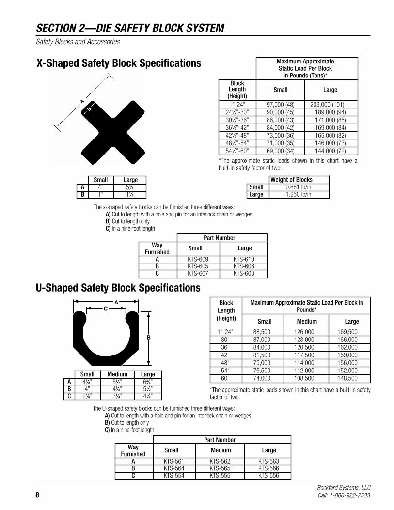
U-Shaped Safety Block SpecificationsA
B
C
1”-24” 88,500 126,000 169,500 30” 87,000 123,000 166,000 36” 84,000 120,500 162,000 42” 81,500 117,500 159,000 48” 79,000 114,000 156,000 54” 76,500 112,000 152,000 60” 74,000 108,500 148,500
Block Length (Height)
Maximum Approximate Static Load Per Block in Pounds*
Small Medium Large
Small Large A 4” 53⁄4” B 1” 11⁄4”
Maximum Approximate Static Load Per Block in Pounds (Tons)*
Block Length Small Large (Height) 1”-24” 97,000 (48) 203,000 (101) 241⁄2”-30” 90,000 (45) 189,000 (94) 301⁄2”-36” 86,000 (43) 171,000 (85) 361⁄2”-42” 84,000 (42) 169,000 (84) 421⁄2”-48” 73,000 (36) 165,000 (82) 481⁄2”-54” 71,000 (35) 146,000 (73) 541⁄2”-60” 69,000 (34) 144,000 (72)
*The approximate static loads shown in this chart have a built-in safety factor of two.
Weight of Blocks Small 0.681 lb/in Large 1.250 lb/in
X-Shaped Safety Block Specifications
*The approximate static loads shown in this chart have a built-in safety factor of two.
The x-shaped safety blocks can be furnished three different ways: A) Cut to length with a hole and pin for an interlock chain or wedges B) Cut to length only C) In a nine-foot length
Part Number Way Small Large Furnished A KTS-609 KTS-610 B KTS-605 KTS-606 C KTS-607 KTS-608
Small Medium Large A 45⁄8” 51⁄2” 63⁄4” B 4” 47⁄8” 51⁄2” C 25⁄8” 31⁄4” 41⁄4”
The U-shaped safety blocks can be furnished three different ways: A) Cut to length with a hole and pin for an interlock chain or wedges B) Cut to length only C) In a nine-foot length
Part Number Way Small Medium Large Furnished A KTS-561 KTS-562 KTS-563 B KTS-564 KTS-565 KTS-566 C KTS-554 KTS-555 KTS-556

Rockford Systems, LLCCall: 1-800-922-7533 9
SECTION 2—DIE SAFETY BLOCK SYSTEMSafety Blocks and Accessories
A
B
A B
Small Medium Large A 45⁄8” 51⁄2” 63⁄4” B 31⁄2” 41⁄4” 51⁄4”
Maximum Approximate Static Load Per Block in Pounds (Tons)* Block Length Small Medium Large (Height) 1”-24” 88,500 (44) 126,000 (63) 169,500 (84) 241⁄2”-30” 87,000 (43) 123,000 (61) 166,000 (83) 301⁄2”-36” 84,000 (42) 120,500 (60) 162,000 (81) 361⁄2”-42” 81,500 (40) 117,500 (58) 159,000 (79) 421⁄2”-48” 79,000 (39) 114,000 (57) 156,000 (78) 481⁄2”-54” 76,500 (38) 112,000 (56) 152,000 (76) 541⁄2”-60” 74,000 (37) 108,500 (54) 148,500 (74)
*The approximate static loads shown in this chart have a built-in safety factor of two.
Octagonal Safety Block Specifications
The octagonal safety blocks can be furnished four different ways: A) Cut to length with a hole and pin for an interlock chain and with an adjustable screw device installed
(order adjustable screw device separately; see page 10 for part numbers and pricing) B) Cut to length with a hole and pin for an interlock chain or wedges C) Cut to length only D) In a nine-foot length
Part Number Way Small Medium Large Furnished A KTS-589 KTS-590 KTS-591 B KTS-592 KTS-593 KTS-594 C KTS-595 KTS-596 KTS-597 D KTS-599 KTS-600 KTS-601

Rockford Systems, LLC10 Call: 1-800-922-7533
SECTION 2—DIE SAFETY BLOCK SYSTEMSafety Blocks and Accessories
Safety Block Accessories
ALUMINUM SAFETY WEDGESThe aluminum safety wedges are used in combination with safety blocks. Because the safety block lengths are less than the die opening, aluminum wedges are available to fill the gap between the safety block and the upper die. Maximum adjustment of the wedges is approximately 11⁄2”. If the gap is more than 11⁄2”, a longer safety block must be used. See the illustration below for proper application.
The aluminum wedges are available in three sizes to match the three safety block cross-sections. When supplied as an assembly, the wedges and safety block are connected together with a heavy-duty chain.
Two-Piece Safety Wedges
The above is an example showing the press slide at top of stroke, with a safety block and wedges inserted, filling the entire die opening. With the wedges installed securely between the top of the safety block and the upper die half, any slide motion is prevented.
Part No. Aluminum Safety Wedges KTS-571 6” Long for Small Block KTS-572 7” Long for Medium Block KTS-573 8” Long for Large Block KTS-570 Safety Wedge Material in a 9’ Length
DieOpening
WedgeWedge
Safety Block
Safety Block
Upper Die
Lower Die
Adjustable Screw DevicesThe adjustable screw device serves the same purpose as the wedges and can be furnished with the octagonal safety blocks. This device mounts on top of the safety block with four machine bolts. It is available with approximately 2, 4, or 6 inches of adjustment if required, and a 1⁄2” diameter hole in the screw allows a rod to be inserted for ease of adjustment. When this option is provided, it is attached to the safety block at the factory.
Adjustable Screw Device
Part No. Description KTS-574 2” Adjustable Screw Device for Small Octagonal Block KTS-575 2” Adjustable Screw Device for Medium Octagonal Block KTS-584 4” Adjustable Screw Device for Small Octagonal Block KTS-585 4” Adjustable Screw Device for Medium Octagonal Block KTS-598 6” Adjustable Screw Device for Large Octagonal Block
(Continued on next page.)

Rockford Systems, LLCCall: 1-800-922-7533 11
SECTION 2—DIE SAFETY BLOCK SYSTEMSafety Blocks and Accessories
Safety Block Accessories (continued)
SAFETY BLOCK HOLDERSThe safety block holder is available in two sizes. It is attached to the side of a machine for storing the safety block assembly. This holder includes a rubber holding strap (part No. KTS-504) to secure the safety block assembly in place.
Part No. Description Shelf Dimensions KTS-003 Small Safety Block Holder 8” x 8” KTS-005 Large Safety Block Holder 101⁄2” x 101⁄2”
ELECTRICAL INTERLOCK SYSTEMSThis device consists of a 1- or 2-contact male plug with a 12” or 24” heavy-duty chain, receptacle, quick link, and mounting box. The chain is connected to the safety block so that the plug must be removed from the receptacle before the safety block can be placed in the die. This is a safety interlock feature that wires electrically into the machine motor control circuit. After wiring properly, the plug is pulled, and the power to the main drive motor and clutch/brake control is disconnected. When the safety block is in use, the machine should not be able to be operated.
Part No. Description KTS-503 One-Contact Interlock System With 12” Chain KTS-518 One-Contact Interlock System With 24” Chain KTS-533 Two-Contact Interlock System With 24” Chain KTS-534 Two-Contact Interlock System With 12” Chain
Electrical Interlock Systems
SAFETY BLOCK LIFTING HANDLEFor larger, heavier safety blocks, a lifting handle is available that can be attached to the safety block. This will provide assistance when installing and removing safety blocks.
Part No. KTS-503
Part No. FSL-007
Part No. Description KTS-515 One-Contact Receptacle KTS-516 One-Contact Plug With 12” Chain KTS-517 One-Contact Plug With 24” Chain KTS-530 Two-Contact Receptacle KTS-531 Two-Contact Plug With 12” Chain KTS-532 Two-Contact Plug With 24” Chain CTK-004 Mounting Box KTS-519 Quick Link
Replacement Parts for Electrical Interlock Systems
KSL-076/0717
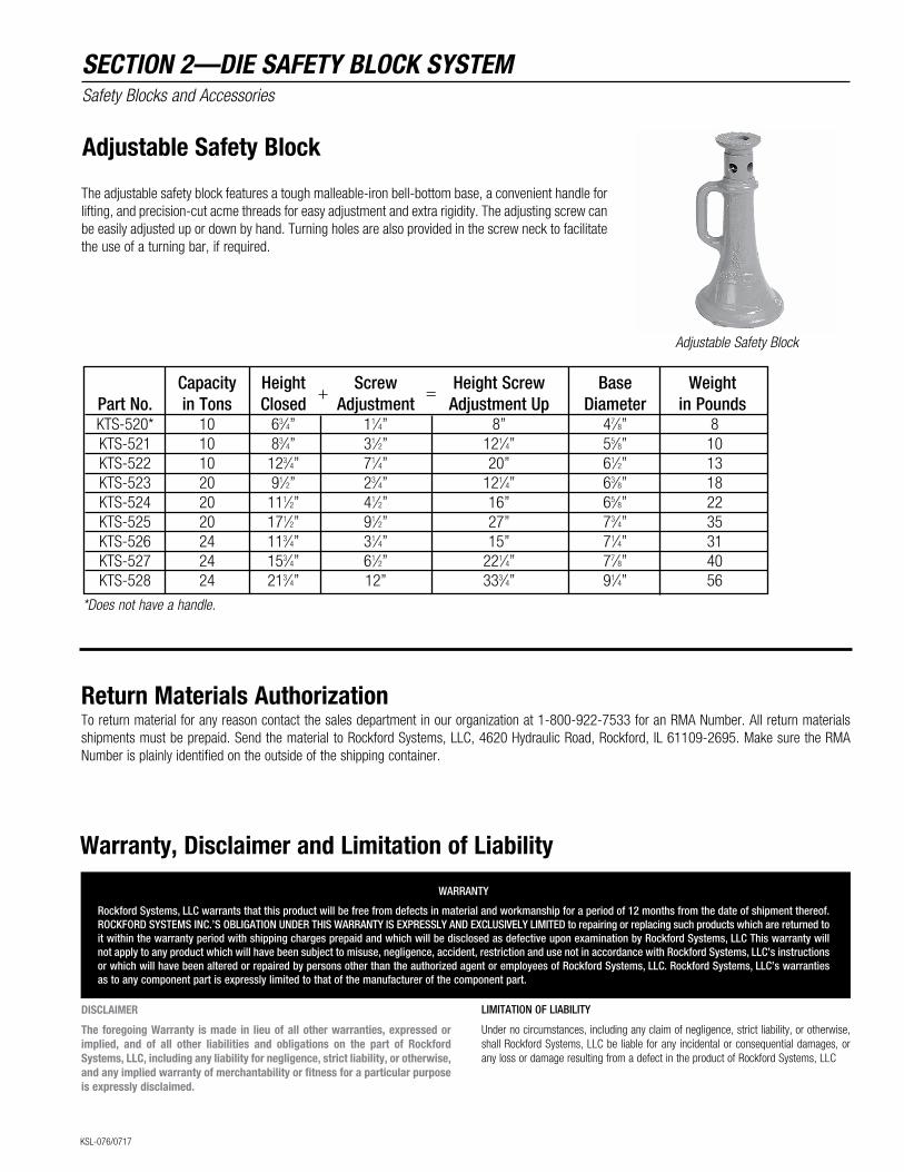
Return Materials AuthorizationTo return material for any reason contact the sales department in our organization at 1-800-922-7533 for an RMA Number. All return materials shipments must be prepaid. Send the material to Rockford Systems, LLC, 4620 Hydraulic Road, Rockford, IL 61109-2695. Make sure the RMA Number is plainly identified on the outside of the shipping container.
Adjustable Safety Block
The adjustable safety block features a tough malleable-iron bell-bottom base, a convenient handle for lifting, and precision-cut acme threads for easy adjustment and extra rigidity. The adjusting screw can be easily adjusted up or down by hand. Turning holes are also provided in the screw neck to facilitate the use of a turning bar, if required.
Capacity Height Screw Height Screw Base Weight Part No. in Tons Closed Adjustment Adjustment Up Diameter in Pounds KTS-520* 10 63⁄4” 11⁄4” 8” 47⁄8” 8 KTS-521 10 83⁄4” 31⁄2” 121⁄4” 55⁄8” 10 KTS-522 10 123⁄4” 71⁄4” 20” 61⁄2” 13 KTS-523 20 91⁄2” 23⁄4” 121⁄4” 63⁄8” 18 KTS-524 20 111⁄2” 41⁄2” 16” 65⁄8” 22 KTS-525 20 171⁄2” 91⁄2” 27” 73⁄4” 35 KTS-526 24 113⁄4” 31⁄4” 15” 71⁄4” 31 KTS-527 24 153⁄4” 61⁄2” 221⁄4” 77⁄8” 40 KTS-528 24 213⁄4” 12” 333⁄4” 91⁄4” 56
+ =
Adjustable Safety Block
*Does not have a handle.
WARRANTY
Rockford Systems, LLC warrants that this product will be free from defects in material and workmanship for a period of 12 months from the date of shipment thereof. ROCKFORD SYSTEMS INC.’S OBLIGATION UNDER THIS WARRANTY IS EXPRESSLY AND EXCLUSIVELY LIMITED to repairing or replacing such products which are returned to it within the warranty period with shipping charges prepaid and which will be disclosed as defective upon examination by Rockford Systems, LLC This warranty will not apply to any product which will have been subject to misuse, negligence, accident, restriction and use not in accordance with Rockford Systems, LLC’s instructions or which will have been altered or repaired by persons other than the authorized agent or employees of Rockford Systems, LLC. Rockford Systems, LLC’s warranties as to any component part is expressly limited to that of the manufacturer of the component part.
LIMITATION OF LIABILITY
Under no circumstances, including any claim of negligence, strict liability, or otherwise, shall Rockford Systems, LLC be liable for any incidental or consequential damages, or any loss or damage resulting from a defect in the product of Rockford Systems, LLC
Warranty, Disclaimer and Limitation of Liability
DISCLAIMER
The foregoing Warranty is made in lieu of all other warranties, expressed or implied, and of all other liabilities and obligations on the part of Rockford Systems, LLC, including any liability for negligence, strict liability, or otherwise, and any implied warranty of merchantability or fitness for a particular purpose is expressly disclaimed.
SECTION 2—DIE SAFETY BLOCK SYSTEMSafety Blocks and Accessories