installation manual for msi extended pipe rout...
TRANSCRIPT

Page 1
Installation Manual for MSI Extended Pipe Rout Libraries By Edwin E Thompson
9/20/2012
Copyright 9/9/2012, 2015 (See Appendix C)
Index
1. Introduction
1.1. Description
1.2. The need to verify accuracy
1.3. The need to verify availability
1.4. General Comments
1.5. Please Do Not distribute MSI extended Library files (See EULA appendix C).
1.6. Systems Requirements
1.7. Reference Materials
2. Installation and Setup of MSI Extended Libraries
2.1. Solidworks Standard Piping Design Library Rules
2.2. Installing the MSI Library
2.3. Setting up Pipe Routing
2.4. Some Common Errors
3. Using the extended Library components in Pipe Routes
3.1. Explanation of starting pipe routs.
3.2. Start at a Point Method
4. Appendices
4.1. A-MSI Library Rules
4.2. B-MSI Flanges and Gaskets
4.3. C-End User License Agreement (EULA)
4.4. D-MSI Extended Libraries (existing future modules)

Page 2
Section 1, Introduction:
1.1 Description:
MSI Extended Library modules are designed to enhance the usability of the Solidworks Pipe Routing
Add-In. This manual uses the Schedule 40 Stainless Steel extended library as an example but can be
used to install a number of MSI extended libraries. See Appendix D for specific component files for each
of the library modules.
Additional MSI extended libraries are expected to be developed. Check back periodically for new library
modules at: http://www.msioregon.com/SW_Products.html
If required components do not appear to be offered, please contact MSI for custom development,
availability, and pricing: [email protected]
1.2 The need to verify accuracy:
The user must check all critical dimensions before use:
1. For the sake of file size and model efficiency, many components have been "simplified". One
example of this is that the ribs on various pipe fittings have not been included. The user needs
to evaluate if these simplifications are acceptable within their designs.
2. While standards may apply, such as the ASME 16 series there may be considerable variations
with actually purchased components. Some sizes (especially larger sizes) have not been verified
with standards. Consideration should always be made with NPT fittings since thread
engagement may vary in actual use.
3. Many dimensions for a number of pipe components are not published or are difficult to
determine. Some models dimensions have been derived or estimated.
1.3 The Need to Verify Availability:
All sizes should be verified to have a reasonable delivery before use.
1.4 General Comments:
No engineering advice is being offered for designs or for the use and selection of any of the extended
library components.
All extended library components use custom "Description" properties to automatically populate route
drawing BOM's. Therefore a Description column may need to be added to drawing BOM's. The result
will be that the description for all piping components within the extended library will be automatically
populated within BOM's. Description properties may need to be modified through editing the
$PRP@Description values in the design tables of the components.

Page 3
The color, material and other minor changes have also been made to SW standard routing components
within the extended library.
MSI extended library parts follow MSI's general guidelines (Appendix A).
1.5 Please Do Not distribute MSI extended Library files:
The user is free to use these components during the course of normal engineering designs. A
considerable amount of time and effort has been spent in developing the MSI Pipe Library. Therefore,
the user is asked to respect the End User License Agreement, especially to not to distribute or upload
MSI part component files to websites or to non-licensed users (please see Appendix C).
1.6 System Requirements:
Solidworks Premium 2013 or above with the "Piping and Routing" add in.
1.7 Reference Material:
Links to product Catalogs and design charts have been added to most of the Design Binders. While MSI
makes no claim of ownership or for accuracy these links are added to assist in the design process.
These references materials are also available through: MSI Design References
To add a quick reference to your desktop, open the reference above and drag the "Web Symbol" (as is
shown below) to the desk top. This will allow the references web page to be quickly displayed.

Page 4
Section 2, Installation of MSI Extended Libraries:
2.1 Solidworks Standard Piping Design Library Rules:
Generally, when using Solidworks Pipe Routing there are three important rules that should be
understood and followed:
Rule 1: All routing and piping files should be located under the Solidworks standard Routing Library
Path, C:\ProgramData\SolidWorks\SolidWorks 2013\design library\routing\ Piping. (If a different
version than SolidWorks 2013 is being used the path should be modified appropriately. As an
example: C:\ProgramData\SolidWorks\SolidWorks 2014\design library\routing\ Piping )
Rule 2: No two part files within this path should ever have the same file name. Therefore any
routing components that have been copied and improved must be renamed before use in any pipe
routs.
Rule 3: Once used in a design, the name and directory locations of individual Piping Components
should not be changed. If changes are made, links will be broken and will need to be manually
corrected.
2.2 Installing the MSI Extended Library:
Note: Refer to Table on page 10 for MSI modules.
Step 1: Download and unzip the MSI Library file into a "C:\2013 MSI Routing Library" directory. (Note:
This directory is not mandatory. The library files are 2013 but can be copied into later versions of
Solidworks.)
The resulting directory should be as is shown below. (Note: SW 2013 is used as an example throughout
this tutorial. Newer versions of Solidworks will need to be modified accordingly).
Step 2: This PDF file should be opened and followed to complete the remaining installation.

Page 5
Step 3: Double Click on "SS pipe.exe" (or the appropriate file provided- see table on page 10) which will
begin the Unzip process. When the dialogue box opens, verify that the "Extract to" location is:
C:\ProgramData\SolidWorks\SolidWorks 2013\design library\routing\ Piping\pipes. (The SolidWorks
2013 designation may need to be changed appropriately for newer versions).
Step 4: Double Click on "SS NPT.exe" (or the appropriate file provided- see table on page 10) which will
begin the Unzip process. When the dialogue box opens verify that the "Extract to" location is:
C:\ProgramData\SolidWorks\SolidWorks 2013\design library\routing\ Piping\pipe\<Directory Name>.
(The SolidWorks 2013 designation may need to be changed appropriately for newer versions. The
Directory Name should be one of the directories shown below. As an example for the SS NPT files need
to be unzipped into the directory: ...\Piping\Sch 40 SS).
If the target directory and some component files already exist, the best practice is to have the original
files renamed as "copies".
2.3 Setting up Pipe Routing:
Step 1: "Pipe Routing" needs to be added in within Solidworks by selecting the Add-ins as is shown
below:

Page 6
When the dialogue box below is displayed. Check the Solidworks Routing options as is shown below:
Note: Routing is only available in Solidworks Premium and above.
When Routing is activated, and a part or assembly or drawing file is opened, "Routing" will be displayed
in the toolbar:
The Routing menu will reveal the following options:

Page 7
Step 2, open the "Routing Library Manager":
Step 3 When the Routing Library Manager is open, the Routing Library and Routing Template directory
locations need to be defined. Select the Routing File Locations and Settings Tab (as is shown below):
The window shown below should be visible.
If the Routing Library directory path is not correct, use the <Browse> buttons on the right (arrow A
below) and select the required path. When done the Routing Library directory should be as is shown
below (refer to section 2.2 above for more information).

Page 8
The template directory should also be set (see arrow B below). Again, the use of the <Browse> button
(towards the right) should be used to identify the location to the MSI route Templates location. This file
can be moved to any location on the HD but the "C:\MSI Routing Library" directory is a good location.
The routing template path could be, "C:\2013 MSI Routing Library\MSI Route Templates.asmdot".
As subsequent versions of Solidworks are loaded, new templates files can be added but they must have
a different name. Such as, "2013 MSI Route Templates.asmdot" or "2014 MSI Route
Templates.asmdot".
Step 4: Once the Routing File Locations and Settings are correct, they should be saved (refer to the right
arrow shown below).

Page 9
Selecting the <Save Settings> button will allow a location for the Routing Settings. A good location for
the first Solidworks version is "C:\2013 MSI Routing Library". However, as subsequent versions of
Solidworks are installed, additional directories may be needed.
Step 5, Setup Piping and Tubing Database:
After the Directories have been properly defined, and the files have been copied, the Piping and Tubing
Database needs to be rebuilt. Under the Routing Library Manager, (1st) select the Piping and Tubing
Database Tab. (2nd) select the Import Data button. (3rd) select the Synchronize button.
This process may take several minutes but when the process is successful, piping components that have
been added under the Routing Library directory path will be included into the database.
Note: If any components in the MSI Extended Library are added, the Piping and Tubing Database will
need to rebuilt.
Step 6, Setting the Route Properties Template:
When the Routing Library directory locations have been properly designated, the MSI Routing
Templates will be automatically loaded. This location is important for loading, saving and reloading if
needed.
1st: As shown below, select the "Route Properties" tab.
2nd: Add New, or Copy and Edit the appropriate "template name" as shown in the Chart below. The
"MSI SS NPT" Template is used for these instructions and is for illustration purposes only.
3rd: By using the browse button, locate and select the appropriate file under the "...piping\pipes\<Pipe
name from chart below>" directory. If the file is not available, the appropriate MSI Pipe module may
need to be downloaded and installed.

Page 10
4th: By using the browse button, locate and select the appropriate file under the
"...Piping\<Directory>\<Elbow from chart below>" directory. If the file is not available, the appropriate
MSI Pipe module may need to be downloaded and installed.
MSI Module Directory
Template Name (2nd) Pipe (3rd) Elbow (4th)
Sch 40 Brass Sch 40 Brass
MSI Brass NPT Brass Pipe.sldprt
Brass 90 Deg elbow.sldprt
Sche 40 Gal Sch 40 Galv MSI Galv NPT
Galv Pipe.sldprt Galv 90 deg elbow.sldprt
Sch 40 Sprinkler
Sch 40 Srinkler
MSI Sprinkler Mal Pipe.sldprt Mal 90 deg elbow.sldprt
Sch 40 SS Sch 40 SS MSI SS NPT SS pipe.sldprt SS 90 Deg elbow.sldprt
Sch 40 Steel Sch 40 Steel MSI Steel NPT Steel pipe.sldprt Steel 90 deg elbow.sldprt
Sch 80 PVC
Sch 80 PVC
MSI PVC
PVC Pipe.sldprt
PVC Elbow.sldprt
SS Tri-Clamp Welded SS Tri-Clamp
MSI SS Tri-Clamp
SS Tri-Clamp Pipe.sldprt
Tri Clamp 90 Deg elbow.sldprt
Welded Welded MSI Welded Steel Weld Pipe.sldprt
Weld Elbow 90deg lr.sldprt
5th: Save the Route Properties Template. When saved, (if everything is correct) the updated file will be
saved at the "C:\2013 MSI Routing Library" location).

Page 11
Step 7, Design Library Setup:
With the files copied to the appropriate directories and the location of the Template directory defined,
the library parts can be added to the Design Library.
First, check if "Piping" is in the Design Library (see below). Note that while the "Piping" directory is
located under the "Routing" directory, both can be added to the Design Library. By adding the "Piping"
directory, a short cut is creates.
If the "Piping" library does not appear in the Design Library (as is shown above) select the <Add File
Location> (the right arrow shown below). The dialogue box will appear and the
"C:\ProgramData\SolidWorks\SolidWorks 3013\design library\routing\piping" folder should be selected.
When "OK" is selected the components in the Piping directory will be available in the Design Library.

Page 12
Step 8, Verify the Piping Component location in the Design Library:
If multiple versions of SW have been loaded, the Piping Component Path should be verified for each
version of the SW Design Library.
Note: If the piping component paths are directed for the wrong version of SW, piping components in the
library will be updated and resaved to the newer version of SW. If this occurs the saved components will
not be useable for the older version of SW. If there are any warning messages about updating pipe
component files during an attempt to save a pipe assembly or part file, DO NOT save. The work will be
lost, but the file should be closed without saving and redone after the path has been corrected.
If even only some of the piping components are updated to a newer version of SW, it is recommended
that the entire piping library be restored from the original download or from appropriate backup files to
the appropriate version of SW. The extended library files are in version 2013 and can be easily refreshed
by following the first step under 2.2 to any version of SW 2013 or later.
To verify the path of the Design Library, right click on the Design Library, "Piping" icon (as is shown
below). The dialogue box should appear. Left Click on the "Open Folder". The Windows Explorer
window should open and reveal the location/ version of SW that is associated with the piping
components. If the piping component directory is located "under" the correct version of SW (shown
below, to the right) then Cancel out of the window (by selecting the "X" in the upper right corner of the
Window Explorer window). If the version is not correct, then the "Piping" location in the Design Library
tree should be "Deleted". This can easily be done by selecting "Delete" (also shown below to the left)
and then re-adding the Piping Location by following the directions provided under "Step 7, Design
Library Setup:" (described in the section above).
If the correct path was selected the Design Library should have the MSI Piping directories and sub-
categories shown below.
Page 13
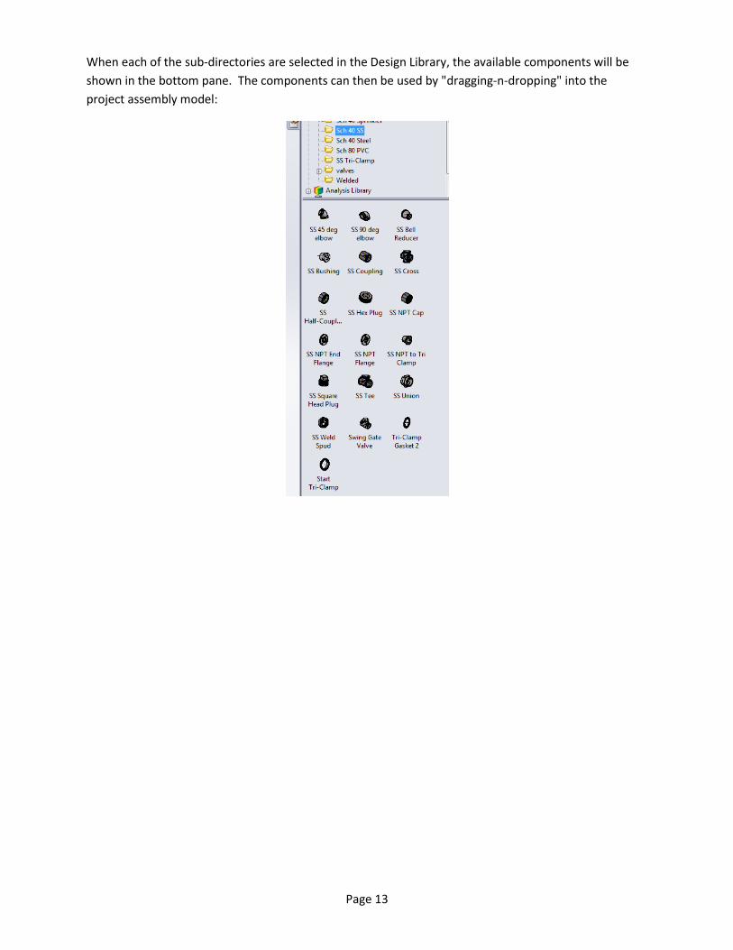
When each of the sub-directories are selected in the Design Library, the available components will be
shown in the bottom pane. The components can then be used by "dragging-n-dropping" into the
project assembly model:

Page 14
Step 9, Add shortcuts and setup the Solidworks Tool bar:
Right click in the Solidworks toolbar and select "Piping" ("A" arrow shown below). This will
activate the Piping Tool Bar.

Page 15
Right click in an open space (again) inside of the Solidworks Toolbar and select "Commands".
The drop down box shown below should appear. When "View" selected, some of the piping
Icons will be displayed.
Drag the "View Routing Points" and the "View Sketches" buttons to the tool bar. These buttons
will later be handy when working within Routing projects.
Step 10, Save the Solidworks settings:
Once the above changes have been made it is recommended to save the Solidworks Settings:
Start/All programs/Solidworks 2013/Solidworks Tools/Copy Settings Wizard. Save the settings
in a location where they can later be restored. One possible location could be the "C:\2013 MSI
Routing Library" directory.

Page 16
2.4 Some Common Errors:
2.4.1 If the following warning appears when starting a new pipe route:
If some of the setup steps described above have not been implemented correctly, the error box
below may be displayed:
The above error could be the cause of a number of setup issues.
1. The part has not been set up properly. The steps to load and setup the Routing Library
Manager and Routing component Wizard should be verified.
2. The part has not been added into the Piping and Tubing Database. This can be corrected by
processing the part through the "Routing component Wizard" or by Synchronizing the
Database.
3. The template has not been setup properly. The routing Template should be verified though
the Route Properties Manager. However, sometimes the error message appears when steps
1 and 2 are correct and the Routing Template is correct. In such a case, it may be necessary
to select a different elbow in the Routing Template (verify that the correct template has
been selected) and then re-select the correct elbow the second time. Apparently, the
process of the re-selection refreshes and corrects an internal error to the Template.
However, if the same elbow, even if it is correct is reselected, the Template will not be
updated.

Page 17
4. Many times this warning can be ignored. To continue:
a. If everything is correct, select "OK".
b. Open the Select Template drop down (A below):
c. The desired type of pipe should be selected (as shown by B above). Continuing on, a
short pipe "stub" should be created.
2.4.2 If the following warning appears when starting a new pipe route by dragging and
dropping:
This warning does not appear often and it is not clear why it is generated. A work around is to
save and close the current assembly, then to open the part in question. While the part in
question is open, re-open the assembly and reattempt to drag and drop the piping component.

Page 18
Section 3, using the extended Library components in Pipe Routes:
If you are familiar with SolidWorks Pipe Routing, the extended library modules are ready for use.
If you are new to Pipe Routing, it is recommended that you purchase and work through the MSI
SolidWorks Piping tutorial. This tutorial is available at http://www.msioregon.com/SW_Products.html
3.1 Using the MSI SS Sch 40 Extended Library (example):
When the library and Solidworks are setup properly the deign library will include "Sch 40 SS". These
components can be used per standard SolidWorks practices:

Page 19
When Pipe Routs are started with SS components, when the Route Properties dialogue Box is displayed,
(shown below) MSI SS NPT should be selected.

Page 20
Section 4, Appendices:
Appendix A, MSI Library Rules:
1. Whenever reasonable part files should include multiple configurations of parts.
2. Design Tables should be used and a "Description" column for automatically filling in Bill of
Material tables ($PRP@Description).
3. The Custom Description Property is useful to identify if a part file is a single part or if it includes
a number of configurations (example: 1/2" to 24" Slip Flange would indicate a multi
configuration part file).
4. PDF's with catalog and or critical design information should be noted or linked in the Design
Journal.
5. To allow for efficient use of library parts, the number of components per family should be kept
in groups of about 20 components. Thus eliminating excessive scrolling. Where it is
appropriate for assemblies to be in the library, all parts that are not usually individually used
should be placed into a sub-folder under the "parent" folder. The number of parts in the "Parts"
folder may be more than 20 since these individual parts are not commonly used.
Appendix B, MSI Flanges and Gaskets:
At least in the older versions of Solidworks, MSI has found flanges and gaskets to be problematic. The
following components have been developed as a work around for these issues:
- SS NPT Flange. 150 lb flange to 1/2" to 24" NPT (similar to a standard 150 lb flange where
flanged fittings need to transition to NPT pipe).
- SS NPT Flange 125. 150 lb flange to 1/2" to 24" NPT (similar to a standard 150 lb flange with a
.125 thk. Gasket). See "MSI SolidWorks Piping tutorial" for further details and use.
- SS NPT Flange 187. 150 lb flange to 1/2" to 24" NPT (similar to a standard 187 lb flange with a
.187 thk. Gasket). See "MSI SolidWorks Piping tutorial" for further details and use.
Note: .125" thick and .187" thick gaskets can be found in the MSI Welded Extended library.
This extended library can be downloaded at: http://www.msioregon.com/SW_Products.html
Appendix C, End User License Agreement:
IMPORTANT INFORMATION – PLEASE READ CAREFULLY
The herein contained License Agreement ("License" or "EULA") shall be considered a legally
binding agreement between You (as an individual or an entity, who then shall, within the
constraints of this agreement, be referred to as "You" or "Your") and Manufacturing Systems Inc. for
the use of the specified software application of MSI Routing Library And Manual, which may include
related printed material, media and any other components and/or software modules, including but
not limited to required drivers ("Product"). Other aspects of the Product may also include, but are
not limited to, software updates and any upgrades necessary that Manufacturing Systems Inc. may
supply to You or make available to You, or that You could obtain after the initial copy of the
Product, and as such that said items are not accompanied by a separate license agreement or terms
of use.

Page 21
BY WAY OF THE INSTALLATION, COPYING, DOWNLOADING, ACCESSING OR OTHERWISE USE OF
THIS PRODUCT, YOU ARE AGREEING TO BE LEGALLY BOUND BY THE HEREIN CONTAINED TERMS
OF THIS LICENSE AGREEMENT. IF YOU DO NOT AGREE TO BE BOUND BY THE TERMS OF THIS
EULA, YOU THEN HAVE NO RIGHTS TO THE PRODUCT AND SHOULD THEREFORE NOT INSTALL,
COPY, DOWNLOAD, ACCESS NOR USE THE PRODUCT.
This Product is hereby protected by copyright laws, as well as any other intellectual property laws.
This Product is licensed and not sold.
LICENSE GRANT
Manufacturing Systems Inc. shall grant to you a non-exclusive license for the use and installation of
the Product subject to all the terms and conditions set forth herein. Furthermore, this EULA shall
also govern any and all software upgrades provided by Manufacturing Systems Inc. that would
replace, over write and/or supplement the original installed version of the Product, unless those
other upgrades are covered under a separate license, at which those terms of that license will
govern.
TERMINATION
Should you breach this EULA at any time, your right to the use of the Product will then immediately
terminate and shall terminate without any notice being given. However, all provisions of this EULA,
with the exception of the License Grant , will remain in effect and thus shall survive termination.
Upon termination of the License Grant, You MUST destroy any and all copies of the Product.
COPYRIGHT
The aforementioned Product is protected by copyright and other intellectual property laws and
treaties, and as such all rights, title, and interest in and to the content offered, including but not
limited to, any photographs, images, video animation, text, and music, that may be incorporated as
part of the offered content. Such offered content is protected by copyright laws and international
treaty provisions. Therefore, offered content must be treated as any other copyrighted material,
with the exception that it is allowable for you to make copies as provided by the License. However,
printed material, which may accompany any offered content, may not be copied.
RESTRICTIONS ON USE
As a Licensee, You may not:
(a) Make use of the offered content on more than one computer at a time, without prior
purchase of additional licenses;
(b) You may not share, distribute, lend, lease, sublicense or otherwise make available, in any
manner whatsoever, to any third party the offered content;
(c) Modify, adapt, create derivative works from or translate any part of the offered content
other than what may be used within Your work in accordance with this License;
(d) Reverse engineer, decompile or disassemble the offered content, nor attempt to locate or
obtain its source code;

Page 22
(e) Attempt to alter or remove any trademark, copyright or other proprietary notice contained
within the offered content; or
(f) Make use of any offered content in any manner not stipulated within this EULA or the
documentation accompanying the offered content.
UPDATES
Manufacturing Systems Inc. may find the need from time to time to make available to all license
holders updates for the offered content, in accordance with the herein contained terms and
conditions of this EULA. It shall be at the sole discretion of Manufacturing Systems Inc. to make
conditional releases of said upgrade to you upon your acceptance of another EULA or execution of
another separate agreement. Should you elect to install and make use of these updates, you are
therefore agreeing to be subject to all applicable license, terms and conditions of this EULA and/or
any other agreement.
DISCLAIMER OF WARRANTY
With regard and with relationship to the maximum extent permitted by applicable law,
Manufacturing Systems Inc., and, if applicable, related suppliers, shall provide the Product and any
support services, if needed, related to the Product, and hereunto disclaim all warranties and
conditions, either express, implied or statutory, which may include, but are not limited to, any
implied warranties or conditions of merchantability, of suitability for a specified purpose, that it
contains absolute accuracy or completeness of responses, of results, and of any lack of negligence or
lack of workmanlike effort, all with respect to the Product, and the provision of or failure to provide
Support Services. FURTHERMORE, THERE IS NO WARRANTY OR CONDITION OF TITLE, QUIET
ENJOYMENT, QUIET POSSESSION, OR NON-INFRINGEMENT WITH REGARDS TO THE HEREIN
CONTAINED PRODUCT. THE ENTIRE RISK AS TO THE QUALITY OF OR PERFORMANCE OF THE
PRODUCT AND SUPPORT SERVICES, IF ANY, REST WITH YOU.
LIMITATION OF LIABILITY AND REMEDIES
In spite of any damages that you may or may not incur for any reason, which may include, but are
not limited to, any and all direct or general damages, the entire liability of Manufacturing Systems
Inc. and/or any of the aforementioned suppliers covered under the herein contained provisions of
this EULA, along with Your exclusive remedy with regards to all of the foregoing, shall hereby be
limited to the amount actually paid by you for this Product . Therefore, the aforementioned
limitations, exclusions and any disclaimers shall apply to the maximum extent allowable by law,
even should any proposed remedy fail its essential purpose.
EXPORT CONTROLS
By clicking on the install button, you hereby agree that you will comply with any and all applicable
export laws, restrictions and all regulations of the U.S. Department of Commerce, U.S. Department
of Treasury, and any other U.S. or foreign agency or authority with regards to this provision of the
EULA. You expressly agree not to export or re-export, nor allow the export or re-export of the
offered content in violation of any such law, restriction or regulation, including without limitation,
export or re-export to any country subject to any and all applicable U.S. trade embargoes or to any
prohibited destination, in any group specified in the current "Supplement No. 1 to Part 740 or the

Page 23
Commerce Control List specified in the then current Supplement No. 1 to Part 738 of the U.S. Export
Administration Regulations (or any successor supplement or regulations)."
U.S. GOVERNMENT END USERS
The offered content is licensed by the U.S. Government with RESTRICTED RIGHTS. The use,
duplication of, or the disclosure by the U.S. Government, shall be subject to restrictions in
accordance with DFARS 252.227-7013 of the Technical Data and Computer Software clause, and 48
DCR 52.227-19 of the Commercial Computer Software clause, as applicable.
MISCELLANEOUS
This EULA, in its entirety, shall be legally binding upon and inure to the benefit of Manufacturing
Systems Inc. and you, our respective successors and permitted assigns. Should any of this provision
be deemed invalid or unenforceable, such determination will not affect the validity or enforceability
of any other provision contained herein. If there is any waiver of any breach or failure to enforce
any of the provisions contained herein, it shall not be deemed as a future waiver of said terms or a
waiver of any other provision of this EULA. Any waiver, supplementation, modification or
amendment to any provision of this EULA, shall only be effective when done so in writing and
signed off by Manufacturing Systems Inc. and you. This EULA shall be governed solely by the laws of
the State of Oregon and of the United States. Should any action arise out of or in relation to this
EULA, such action may be brought exclusively in the appropriate federal or state court in Tigard,
Oregon, and as such, you and Manufacturing Systems Inc. irrevocably consent to the jurisdiction of
said court and venue for Tigard, Oregon.
A .186 inch thick Weld Flange Gasket has also been added. If a different thickness or material of gasket
is needed, this file can be copied and modified as necessary. The intent of this file is to provide a
foundation so that alternative gaskets can be easily developed. Gasket sizes are usually available from
1/4" to 96". Care should always be taken to verify that available sizes can be purchased or custom
manufactured when designing piping routs.
Appendix D, MSI Extended Libraries:
Pipes:
Note: Verify that sizes have a reasonable delivery before use.
Additional types of pipes have been added:
Brass Pipe, 1/8" to 14", Schedule 20,40,60,80,100,120,140,160.
- Galvanized Pipe, 1/8" to 14", Schedule 20,40,60,80,100,120,140,160.
- Malleable Pipe, 1/8" to 14", Schedule 20,40,60,80,100,120,140,160.
- Pipe (Solidworks Standard Pipe file).
- PVC Pipe, 1/2" to 12" Schedule 80 PVC .
- Stainless Steel Pipe, 1/8" to 14", Schedule 20,40,60,80,100,120,140,160.
- Tri-Clamp Stainless Steel Pipe, 1/2" to 6", Schedule 065.
- Steel Pipe, 1/8" to 14", Schedule 20,40,60,80,100,120,140,160.

Page 24
- Steel Weld Pipe, 1/8" to 14", Schedule 20,40,60,80,100,120,140,160.
- Stainless Steel tubing, .062 to 8", multiple wall thicknesses.
Sch 40 Brass:
Note: Verify that sizes have a reasonable delivery before use.
- 45 Deg elbow, 1/8" to 4".
- 90 Deg elbow, 1/8" to 4".
- Bell Reducer, 1/4" to 6".
- Bushing, 1/4" to 4".
- Cross, 1/8" to 4".
- Half Coupling, 1/8" to 6".
- Hex Plug, 1/8" to 4".
- Cap, 1/8" to 4".
- 150 lb Flange to 1/2" to 6" NPT.
- Square Head Plug, 1/8" to 4".
- Tee, 1/8" to 4".
- Union, 1/8" to 4".
Sch 40 Galv (Galvanized):
Note: Verify that sizes have a reasonable delivery before use.
- 45 Deg elbow, 1/8" to 6".
- 90 Deg elbow, 1/8" to 6".
- Bell Reducer, 1/4" to 6".
- Bushing, 1/8" to 4".
- Coupling, 1/8" to 6".
- Cross, 1/8" to 4".
- Hex Plug, 1/8" to 4".
- Cap, 1/8" to 4".
- 150 lb Flange to 1/2" to 24" NPT.
- Square Head Plug, 1/8" to 4".
- Tee, 1/8" to 6".
- Union, 1/8" to 4".
Sch 40 Sprinkler:
Note: Verify that sizes have a reasonable delivery before use.
Note: Groves are not formed in the pipe models for simplicity so they will need to be specified.
- Ductile Groove Cap, 1/8" to 12".
- Ductile Groove Cross, 1/8" to 14".
- Ductile Groove 11.25 Deg Elbow, 1/8" to 16".
- Ductile Groove 22.5 Deg Elbow, 1/8" to 16".

Page 25
- Ductile Groove 45 Deg Elbow, 1/8" to 16".
- Ductile Groove 90 Deg Elbow, 1/8" to 16".
- 150 lb Flange to Ductile Groove Adapter, 2" to 12".
- Ductile Groove Reducer, 2" x 1" to 14" x 12".
- Ductile Groove Tee, 1-1/4" to 14".
- Ductile Groove Clamp, 1" to 24". (Hover Clamp over groove edge for placement).
- Malleable Iron 90 Deg Elbow, 1/8" to 6".
- Malleable Iron 90 Deg Reducing Elbow, 1" x 1/2" to 4" x 3".
- Malleable Iron Bell Reducer, 1/4" x 1/8" to 6" x 5".
- Malleable Iron Coupling, 1/8" to 6".
- Malleable Cross, 1/8" to 6".
- Malleable Iron Cap, 1/8" to 4".
- Malleable Iron Reducing Cross, 3/4" x 1/2" to 3" x 2".
- Malleable Iron Reducing Tee, 1" x 1/2" to 6" x 4".
- Malleable Iron Tee, 1/8" to 6".
- Malleable Weld Pipe Spud, 2" x 3/4" to 16" x 1".
Sch 40 Stainless Steel:
Note: Verify that sizes have a reasonable delivery before use.
- 45 Deg elbow, 1/8" to 6".
- 90 Deg elbow, 1/8" to 6".
- Bell Reducer, 1/4" x 1/8" to 6" x 5".
- Bushing, 1/4" to 8".
- Coupling, 1/8" to 6".
- Cross, 1/8" to 6".
- Half Coupling, 1/8" to 6".
- Hex Plug, 1/8" to 4".
- Cap, 1/8" to 4".
- SS NPT Flange, 1/2" to 24" (Standard 150 lb flange to NPT pipe transition).
- SS NPT Flange 125, 1/2" to 24" (Standard 150 lb flange to NPT pipe with a .125 gap for a .125
gasket - See Appendix B)
- SS NPT Flange 187, 1/2" to 24" (Standard 150 lb flange to NPT pipe with a .187 gap for a .187
gasket - See Appendix B)
- Square Head Plug, 1/8" to 4".
- Tee, 1/8" to 6".
- Union, 1/8" to 4".
Sch 40 Steel:
These pipe fitting models represent "Generic" components so additional specifications must be
designated if used in designs. The intent of these models is a good start towards the development of
other specific types of Schedule 40 material components. All dimensions should be verified before use.

Page 26
- 45 Deg elbow, 1/8" to 8".
- 90 Deg elbow, 1/8" to 8".
- Bell Reducer, 1/4" to 8".
- Bushing, 1/4" to 8".
- Coupling, 1/8" to 6".p
- Cross, 1/8" to 6".
- Half Coupling, 1/8" to 6".
- Hex Plug, 1/8" to 4".
- Cap, 1/8" to 8p".
- 150 lb Flange to 1/2" to 24" NPT.
- Square Head Plug, 1/8" to 4".
- Tee, 1/8" to 8".
- Union, 1/8" to 4".
- Weld Spud, 1/4" to 4".
Sch 80 PVC:
Note: Verify that sizes have a reasonable delivery before use. There may be slight variations in
dimensions from different suppliers so all dimensions should be checked.
- Cap, 1/2" to 4".
- Coupling, 1/2" to 12".
- Slip to Male NPT, 1/2" to 4".
- Slip to Female NPT, 1/2" to 4".
- Cross, 1/2" to 4".
- 90 Deg Elbow, 1/2" to 4".
- Reducer, 3/4" x 1/2" to 12" x 8".
- Tee, 1/2" to 4".
- Union, 1/2" to 4".
SS Tri-Clamp Purchased:
Note: Verify that sizes have a reasonable delivery before use. There may be slight variations in
dimensions from different suppliers so all dimensions should be checked.
- Tri-Clamp, 1/2" to 4" Cap with 1/2" NPT.
- Tri-Clamp, 1/2" to 4" with 3/4" NPT.
- Tri-Clamp Cap, 1/2" to 4".
- Tri-Clamp Clamp, 1/2" to 4".
- Tri-Clamp Reducer, 3/4" x 1/2" to 6" x 4".
- Tri-Clamp Cross, 1" to 8".
- Tri-Clamp 45 Deg Elbow, 1/2" to 8".
- Tri-Clamp Tee, 1/2" to 8".
- Tri-Clamp Gasket, 1/2" to 6".
- Tri-Clamp to NPT, 1" x 3/4" to 4" x 2".
- Tri-Clamp, 1" to 4" to 3/4" to 3" NPT.

Page 27
- Tri-Clamp Elbow, 1/2" to 8".
SS Tri-Clamp Tubing (Welded .065 Thk Wall):
Note: Verify that sizes have a reasonable delivery before use. There may be slight variations in dimensions from different suppliers so all dimensions should be checked.
- 90 Deg Weld Elbow, 1/2" to 6".
- Medium Weld Flange, 1/2" to 4"
- Short Weld Flange, 1/2" to 12"
- Short Weld Flange (Start), 1/2" to 12"
- Tee, 1/2" to 8"
SW NPT:
These component models are Solidworks Class 2000, 3000, and 6000 part files. They have been
reorganized for ease of use. Material has not been specified. There are no design notes. A
"Description" has been added for Bills of Materials.
- 45 Deg Elbow, 1/8" to 4".
- 90 Deg Elbow, 1/8" to 4".
- Cap, 1/8" to 4".
- Coupling, 1/8" to 4".
- Cross, 1/8" to 4".
- Half Coupling, 1/8" to 4".
- Lateral, 1/8" to 2-1/2".
- Reduce Coupling, 1/4" x 1/8" to 4" x 3".
- Tee, 1/8" to 4".
- Union, 1/8" to 3"
SW Std:
It is recommended to move all of the original Solidworks files under the SW Std directory.
Welded
Generally, these files are the original Solidworks files with additions and minor changes. All sizes should
be verified to have a reasonable delivery before use. There may be slight variations in dimensions from
different suppliers so all dimensions should be checked. Files generally include schedule 40, 80, and
160.
- MSI Flange Gasket 125, (These gaskets will be used for all types of piping requiring a .125" thick
gasket- New).
- MSI Flange Gasket 187, (These gaskets will be used for all types of piping requiring a .187" thick
gasket- New).
- Weld Cap, 1/2" to 24", 150, 300, 600 lb. (New)
Page 28
- Reducing Cross, 1/2" x 1/2" x 1/4" to 14" x 14" x 8".
- Cross, 1/2" to 14".
- 180 Deg 3r Elbow, 2" to 14".
- 180 Deg Lr Elbow, 1/2" to 14".
- 180 Deg Sr Elbow, 1-1/4" to 14".
- 45 Deg 3r Elbow, 2" to 14".
- 45 Deg Lr Elbow, 1/2" to 14".
- 90 Deg 3r Elbow, 2" to 14".
- 90 Deg Lr Elbow, 2" to 14".
- 90 Deg Sr Elbow, 1-1/4" to 14".
- Weld Flange Slip On, 1/2" to 63", (sizes vary for each schedule).
- Weld Flange Slip On 125, 1/2" to 63", (sizes vary for each schedule- A .125" gap is generated for
.125" gaskets).
- Weld Flange Slip On 187, 1/2" to 63", (sizes vary for each schedule- A .187" gap is generated for
.187" gaskets).
- Weld Flange Socket, 1/2" to 24", (sizes vary for each schedule).
- Weld Flange Socket 125, 1/2" to 24", (sizes vary for each schedule- A .125" gap is generated for
.125" gaskets).
- Weld Flange Socket 187, 1/2" to 24", (sizes vary for each schedule- A .187" gap is generated for
.187" gaskets).
- Weld Neck Flange, 1/2" to 24", (sizes vary for each schedule).
- Weld Neck Flange 125, 1/2" to 24", (sizes vary for each schedule- A .125" gap is generated for
.125" gaskets).
- Weld Neck Flange 187, 1/2" to 24", (sizes vary for each schedule- A .187" gap is generated for
.187" gaskets).
- Ecc Reducer, 3/4" x 3/8" to 12" x 10", (schedules 40,80,160).
- Concentric Reducer, , 3/4" x 3/8" to 12" x 10", (schedules 40,80,160).
- Reducer Tee, 1/2" x 1/2" x 1/4" to 14" x 14" x 8".
- Tee, .5" to 14".
- Threadolet, 1" and 2" for 2" to 16" Pipe.
- Weldolet, 1" and 2" for 2" to 16" Pipe.