installation manual for mi-t-m in-ground fiberglass pit ... · in-ground fiberglass pit system...
TRANSCRIPT
Mi-T-M® In-Ground Fiberglass Pit System Operator's Manual �
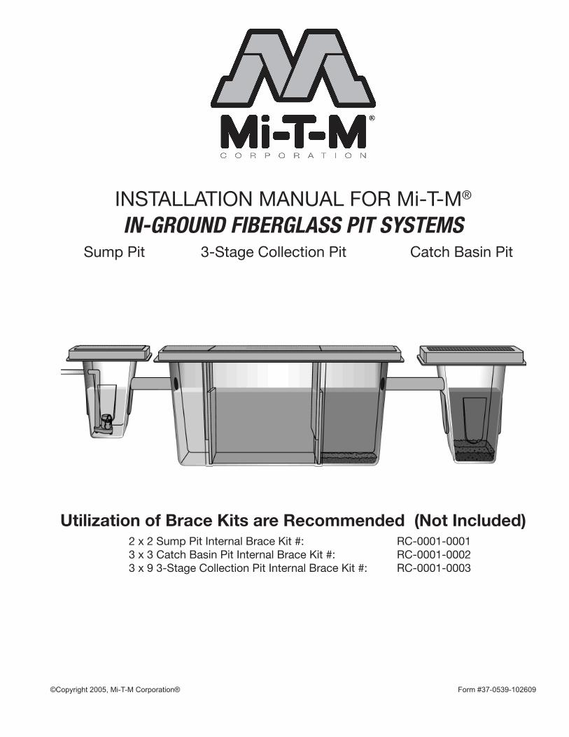
INSTALLATION MANUAL FOR Mi-T-M®
IN-GROUND FIBERGLASS PIT SYSTEMS Sump Pit 3-Stage Collection Pit Catch Basin Pit
©Copyright 2005, Mi-T-M Corporation® Form #37-0539-�02609
Utilization of Brace Kits are Recommended (Not Included)2 x 2 Sump Pit Internal Brace Kit #: RC-0001-00013 x 3 Catch Basin Pit Internal Brace Kit #: RC-0001-00023 x 9 3-Stage Collection Pit Internal Brace Kit #: RC-0001-0003
2 Mi-T-M® In-Ground Fiberglass Pit System Operator's Manual
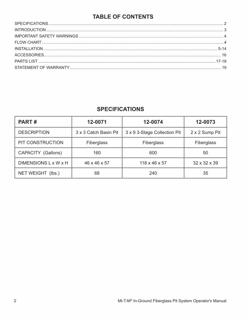
specifications
taBLe of contentsSPeCIFICaTIOnS ........................................................................................................................................................... 2InTRODUCTIOn ............................................................................................................................................................. 3IMPORTanT SaFeTy WaRnInGS ................................................................................................................................ 4FLOW CHaRT ................................................................................................................................................................. 4InSTaLLaTIOn .......................................................................................................................................................... 5-�4aCCeSSORIeS............................................................................................................................................................. �6PaRTS LIST ............................................................................................................................................................. �7-�8STaTeMenT OF WaRRanTy ...................................................................................................................................... �9
paRt # 12-0071 12-0074 12-0073
DeSCRIPTIOn 3 x 3 Catch Basin Pit 3 x 9 3-Stage Collection Pit 2 x 2 Sump Pit
PIT COnSTRUCTIOn Fiberglass Fiberglass Fiberglass
CaPaCITy (Gallons) �60 600 50
DIMenSIOnS L x W x H 46 x 46 x 57 ��8 x 46 x 57 32 x 32 x 39
neT WeIGHT (lbs.) 68 240 35
Mi-T-M® In-Ground Fiberglass Pit System Operator's Manual 3
Congratulations on the purchase of your new Mi-T-M Fiberglass Pit System! Mi-T-M offers premium quality fiberglass pit components boasting features created with the customer in mind to exceed the performance of any concrete pit system.
Mi-T-M helps you create the appropriate pre-treatment pit system for your Wash-Water Recycle or Sewer Discharge operations. The various pit components are designed to conform to the unique requirements of each customer's indi-vidual water treatment design. Mi-T-M Fiberglass Pit Systems are designed for sublevel applications that offer a wide variety of usages including:
Rental YardsHeavy Equipment DealersTrucking FacilitiesGolf CoursesMilitary BasesTruck Rental FleetsForklift Washing OperationsAircraft Maintenance & RestorationShipyardsDiesel Repair FacilitiesEngine Rebuilders & ManufacturersOil Fields
This installation manual was compiled for your benefit. By reading and following the simple safety and installation steps described in this manual, you will receive years of trouble free operation from your new Mi-T-M Fiberglass Pit System. The contents of this manual are based on the latest product information available at the time of publication. Mi-T-M reserves the right to make changes in price, color, materials, equipment, specifications or models at any time without notice.
aLWaYs pRoViDe a copY of tHis ManUaL to anYone UsinG tHis eQUipMent. ReaD aLL instRUctions BefoRe instaLLinG tHis fiBeRGLass pit sYsteM anD especiaLLY point oUt tHe "safetY WaRninGs" to pReVent tHe possiBiLitY of peRsonaL inJURY to tHe opeRatoR.
Inspect for signs of obvious or concealed freight damage. If damage does exist, file a claim with the transportation company immediately. Be sure that all damaged parts are replaced and that the mechanical and electrical problems are corrected prior to operation of the unit. If you require service, contact Mi-T-M Customer Service.
CaLL OUR TOLL-FRee nUMBeR
800-553-9053
for the Sales or Service Center nearest you!
Please have the following information available for all service calls:
�. Part number
2. Date and Place of Purchase
intRoDUction
Lightweight-Significantly easier installation.-Minimal shipping fees.
Economical-Considerably less expensive.-Accepts universal coalescing grids instead of custom made baffles.
High Performance Construction-Conforms to Current Government Regulations.-Earthquake resistant.-Chemical & pH resistant.-Double wall construction design. Versatile
-Designed for a variety of usages.

4 Mi-T-M® In-Ground Fiberglass Pit System Operator's Manual
As pressure washers are being operated, used water flows into the Wash Water catch pit (1). From there, it moves into the core of the system; the 3-stage collection pit (2). The performance of this pit regulates the performance of your entire system. This pit is designed to remove initial contaminants from the system. Increasing the amount of contaminants removed at this stage, increases the life of the remaining components in your system. after moving through a series of cleansing weirs in the 3-Stage Collection pit, the water flows into the sump pit (3). Water is then pumped into the Reclamation Unit for final cleansing before being sent back to the pressure washers.
RisK of BoDiLY inJURY Injury may occur from the In-ground Fiberglass Pit System.
potentiaL conseQUence pReVention
iMpoRtant safetY WaRninGsReaD aLL SaFeTy WaRnInGS BeFORe InSTaLLInG In-GROUnD FIBeRGLaSS PIT SySTeM
Do not install without reading and understanding the entire manual. Improper installation will void warranty. DO nOT overreach or stand on unstable support including pit bracing. Wet surfaces can be slippery, wear protective foot gear and keep good footing and balance at all times.
DO nOT DRInK THe WaTeR In THe In-GROUnD FIBeRGLaSS PIT SySTeM!! This is non-potable water and is not suitable for consumption.Do not submerge yourself or pets into an operable pit.
!saVe tHese instRUctions!
PIT
S00
9-06
0299
-jTR
fLoW cHaRt
HaZaRD
Mi-T-M® In-Ground Fiberglass Pit System Operator's Manual 5
PIT
S0�
0-06
0299
-jTR
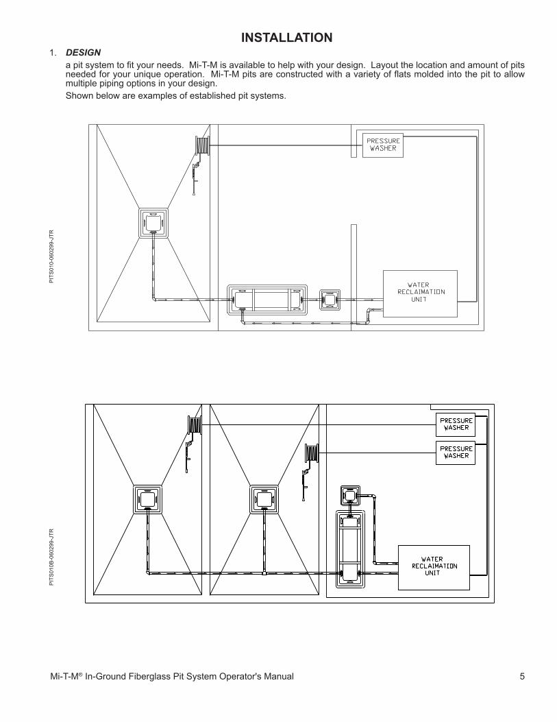
instaLLation�. DESIGN a pit system to fit your needs. Mi-T-M is available to help with your design. Layout the location and amount of pits
needed for your unique operation. Mi-T-M pits are constructed with a variety of flats molded into the pit to allow multiple piping options in your design.
Shown below are examples of established pit systems.
PIT
S0�
0B-0
6029
9-jT
R

6 Mi-T-M® In-Ground Fiberglass Pit System Operator's Manual
instaLLation
EARTH EARTH
EARTH
2. EXCAVATE an area which will allow a wall of concrete under and around all the sides of the pit which you are installing. The
thickness of the concrete housing should be a minimum of 4" and a maximum of 8". The housing should be equal to the slab thickness at the pit surface unless the slab thickness exceeds 8". In this case, an 8" maximum concrete housing is sufficient. Angle the edges of the excavated area to allow the slab to solidly conform to the concrete housing.
2.� If you are installing the pits in an area where you must cut through an existing concrete bed before excavating, use the dimensions shown below. all other instructions in this manual will apply to your installation.
PIT
-000
6-06
�799
-jTR
PIT
-000
3-06
�799
-jTR
PIT
-000
8-06
�799
-jTR
3x9 pit
2X2 pit 3x3 pit
eaRTH

Mi-T-M® In-Ground Fiberglass Pit System Operator's Manual 7
2.2 If you are excavating new pits, use the dimensions shown below. all other instructions in this manual will apply to your installation.
PIT
-000
�-06
�799
-jTR
4. PLACE the Pit(s) on top of the concrete block(s) in their designated area(s). Keep in mind each Pit is molded with flats in
several locations to conform to the unique requirements of each customer's individual design. Position the pit to ensure a plumbing connection lines up with a flat. It is not recommended to cut plumbing connection holes in the flat at this time because the pits are too unstable. The hole cutting step of the installation is best completed after the initial concrete pour. Once the pit is stabilized in concrete, the stress on the plumbing connections is significantly reduced, helping prevent future leaks.
EARTH
FLAT
PIT
-000
4-06
�799
-jTR
PIT
-000
7-06
�799
-jTR
EARTH EARTH
FLATFLAT FLAT
3. LEVEL the floor of the excavation and set concrete blocks in the areas where the Pit(s) will be placed. The 3-Stage Collection
Pit requires three concrete blocks while the remaining pits need only one. Place a level across the concrete blocks to ensure they create an even plane for the Pit(s) to rest upon.
instaLLation
3x3 pit2X2 pit
3x9 pit
eaRTH

8 Mi-T-M® In-Ground Fiberglass Pit System Operator's Manual
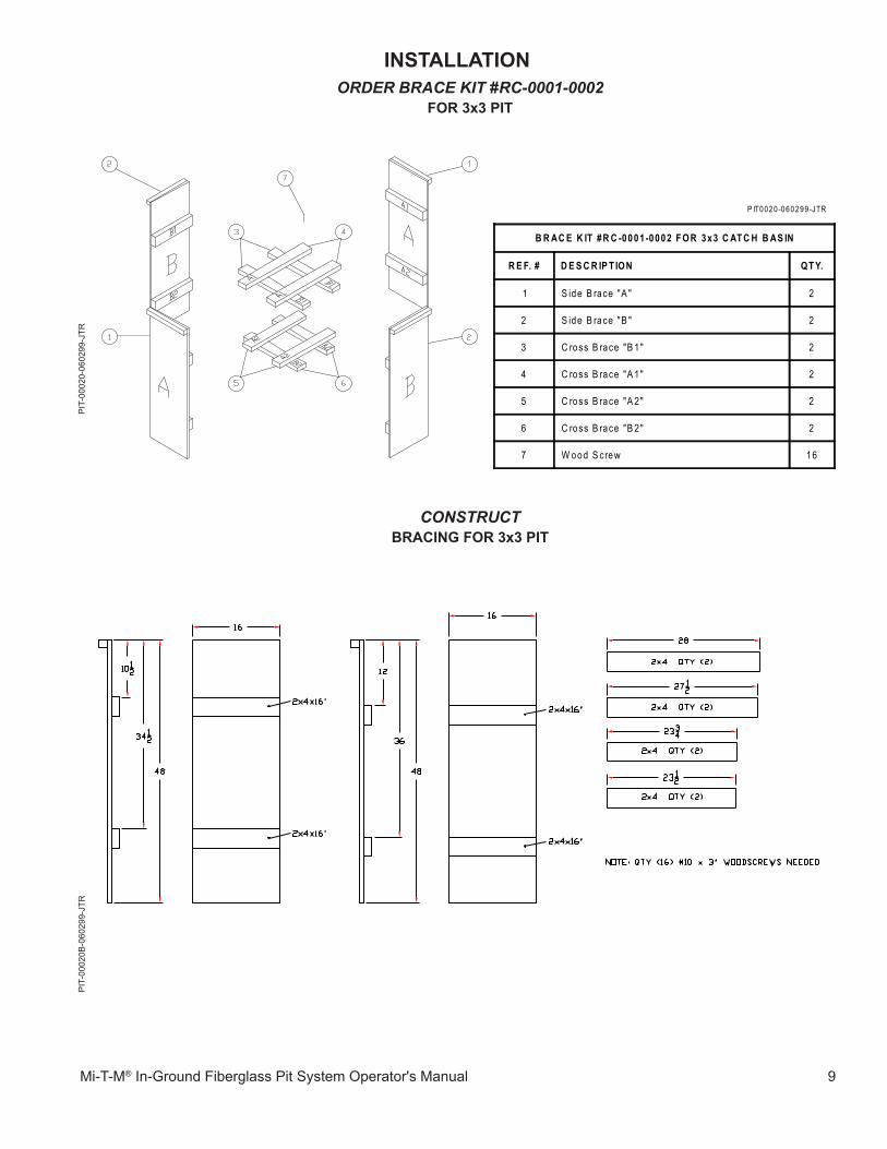
5. BRACE the Pit(s). Brace kits are required for sublevel placement of pits to prevent movement while pouring the concrete
housing. Bracing may be accessed in one of two ways:a. Order Brace Kits through your local distributor using the part numbers that correspond with your pit. These kits
are reusable and therefore may also be utilized in future installations. Use the appropriate Brace Kit following the instructions provided for proper installation.
b. Construct the desired Brace Kit using the dimensions shown in this manual.
instaLLation
ORDER BRACE KIT #RC-0001-0001 foR 2x2 pit
PIT
-000
�9-0
6029
9-jT
R
CONSTRUCTBRace Kit foR 2x2 pit
PIT
-000
�9B
-060
299-
jTR
P IT0019-060299-JTR
B R AC E K IT #R C -0001 -0001 F OR 2x2 S U M P P IT
R E F. # D E S C R IP T ION QT Y.
1 S ide B race -2 C ross B a rs 2
2 S ide B race -1 C ross B a r 2
3 C ross B race "B " 1
4 C ross B race "A " 1
5 Lower B race 1
6 W ood S crew 7
Mi-T-M® In-Ground Fiberglass Pit System Operator's Manual 9
ORDER BRACE KIT #RC-0001-0002 foR 3x3 pit
PIT
-000
20-0
6029
9-jT
R
instaLLation
CONSTRUCTBRacinG foR 3x3 pit
PIT
-000
20B
-060
299-
jTR
P IT0020-060299-JTR
B R AC E K IT #R C -0001 -0002 F OR 3x3 C AT C H B AS IN
R E F. # D E S C R IP T ION QT Y.
1 S ide B race "A " 2
2 S ide B race "B " 2
3 C ross B race "B 1" 2
4 C ross B race "A 1" 2
5 C ross B race "A 2" 2
6 C ross B race "B 2" 2
7 W ood S crew 16

�0 Mi-T-M® In-Ground Fiberglass Pit System Operator's Manual
ORDER BRACE KIT #RC-0001-0003 for 3x9 3-stage collection pit
PIT
-000
2�-0
6029
9-jT
RinstaLLation
P IT0021-060299-JTR
B R AC IN G-L AR GE P IT
R E F. # D E S C R IP T ION QT Y.
1 S ide B race "D " 2
2 C ross B race "D 1 -A " 2
3 S ide B race "A " 2
4 C ross B race "A 2 , B 2 , C 2" 6
5 C ross B race "D 2" 2
6 C ross B race "A 1 , B 1 , C 1" 6
7 W ood S crew 44
8 S ide B race "B " 2
9 S ide B race "C " 2
10 C ross B race "D 1 -B " 2
11 C ross B race "D 2 -B " 2

Mi-T-M® In-Ground Fiberglass Pit System Operator's Manual ��
CONSTRUCT BRACING foR 3x9 3-staGe coLLection pit
PIT
-000
2�B
-060
299-
jTR
instaLLation

�2 Mi-T-M® In-Ground Fiberglass Pit System Operator's Manual
instaLLationP
IT-0
002B
-06�
599-
jTR
6. STABILIZE the pits with angle irons (or the equivalent) to prevent
the pits from rising while the concrete housing is being poured.
7. POUR the �st of 3 phases of concrete. This phase should
cover the concrete blocks and approximately the first �/3 of the pit. allow the concrete to cure for 24 hours. Do not pour concrete completely to the top of the pit. Doing so can create enough pressure to force the pits to rise, and possibly bend the angle iron supports.
PIT
-000
5B-0
6�59
9-jT
R
Mi-T-M® In-Ground Fiberglass Pit System Operator's Manual �3
EARTH
EARTH
PIT
-000
2-06
�599
-jTR
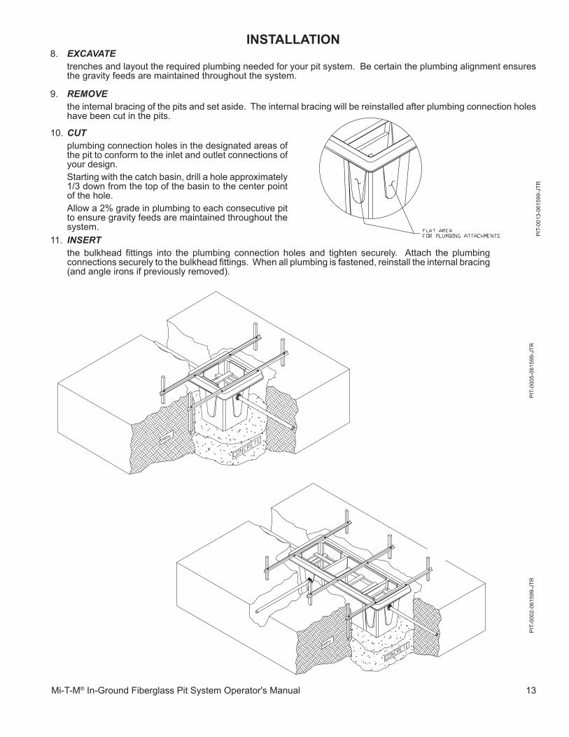
instaLLation8. EXCAVATE trenches and layout the required plumbing needed for your pit system. Be certain the plumbing alignment ensures
the gravity feeds are maintained throughout the system.
9. REMOVE the internal bracing of the pits and set aside. The internal bracing will be reinstalled after plumbing connection holes
have been cut in the pits.
��. INSERT the bulkhead fittings into the plumbing connection holes and tighten securely. Attach the plumbing
connections securely to the bulkhead fittings. When all plumbing is fastened, reinstall the internal bracing (and angle irons if previously removed).
�0. CUT plumbing connection holes in the designated areas of
the pit to conform to the inlet and outlet connections of your design.
Starting with the catch basin, drill a hole approximately �/3 down from the top of the basin to the center point of the hole.
allow a 2% grade in plumbing to each consecutive pit to ensure gravity feeds are maintained throughout the system.
PIT
-000
5-06
�599
-jTR
PIT
-00�
3-06
�599
-jTR

�4 Mi-T-M® In-Ground Fiberglass Pit System Operator's Manual
PIT
-000
2-06
�599
-jTR
NOTE: Inlet portion of pit is the larger of the two end compartments.
instaLLation
EARTH
inLet option B: center of hole should be 7" from top rim of pit.
inLet option a: center of hole should be 7" from top rim of pit.
Mi-T-M® In-Ground Fiberglass Pit System Operator's Manual �5
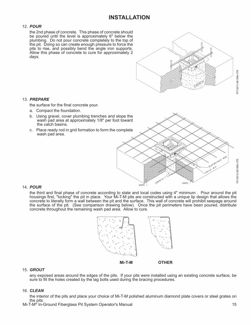
�2. POUR the 2nd phase of concrete. This phase of concrete should
be poured until the level is approximately 6" below the plumbing. Do not pour concrete completely to the top of the pit. Doing so can create enough pressure to force the pits to rise, and possibly bend the angle iron supports. allow this phase of concrete to cure for approximately 2 days.
instaLLation
EARTH
�3. PREPARE the surface for the final concrete pour.
a. Compact the foundation.b. Using gravel, cover plumbing trenches and slope the
wash pad area at approximately �/8" per foot toward the catch basins.
c. Place ready rod in grid formation to form the complete wash pad area.
�4. POUR the third and final phase of concrete according to state and local codes using 4" minimum . Pour around the pit
housings first, "locking" the pit in place. Your Mi-T-M pits are constructed with a unique lip design that allows the concrete to literally form a wall between the pit and the surface. This wall of concrete will prohibit seepage around the surface of the pit. (See comparison drawing below). Once the pit perimeters have been poured, distribute concrete throughout the remaining wash pad area. allow to cure.
�
EARTHEARTH
PIT
-00�
�-06
�599
-jTR
PIT
-00�
2-06
�599
-jTR
�5. GROUT any exposed areas around the edges of the pits. If your pits were installed using an existing concrete surface, be
sure to fill the holes created by the lag bolts used during the bracing procedures.
�6. CLEAN the interior of the pits and place your choice of Mi-T-M polished aluminum diamond plate covers or steel grates on
the pits.
Mi-t-M otHeR

�6 Mi-T-M® In-Ground Fiberglass Pit System Operator's Manual
accessoRies
coaLescinG pacKs for 3-Stage Collection Pit .................................................. #855-00�3BULKHeaD fittinGs 3" slip x FnPT ................................................................................ #55-2248 4" slip x FnPT ................................................................................ #55-2448coVeRs: 2 x 2 Diamond Plate ....................................................................... #56-0030 3 x 3 Diamond Plate ....................................................................... #56-003� 3 x 9 Diamond Plate (3 Sections) .................................................. #56-0032 2 x 2 Steel Grate ............................................................................ #20-0479-a0� 3 x 3 Steel Grate (Qty. 2 required) ............................................... #20-0480-a0�
optionaL accessoRY specifications
USeD On: PIT 3 x 3�2-007�
PIT 3 x 9�2-0074
PIT 2 x 2�2-0073
COVeR COnSTRUCTIOn aluminum Polished Diamond Plate
aluminum Polished Diamond Plate
aluminum Polished Diamond Plate
SUPPORT STRenGTH 450 lbs. 450 lbs. 450 lbs.
DIMenSIOnS L x W x H 36 x 36 x 2 36 x ��0 x 2 24 x 24 x 2
neT WeIGHT (lbs.) 30 83 �6
NOTE: COVERS ARE NOT DESIGNED FOR VEHICLE TRAFFIC
COVeR COnSTRUCTIOn Steel Grate -- Steel Grate
SUPPORT STRenGTH 4,8�4 lbs/ft2 -- 7,3�6 lbs/ft2
DIMenSIOnS L x W x H �7.5 x 36 x 2.5 each -- 24 x 24 x 2
neT WeIGHT (lbs.) 62 each (2 required) -- 96
PIT
00�7
-060
299-
jTR
PIT
00�8
-060
299-
jTR
Mi-T-M® In-Ground Fiberglass Pit System Operator's Manual �7
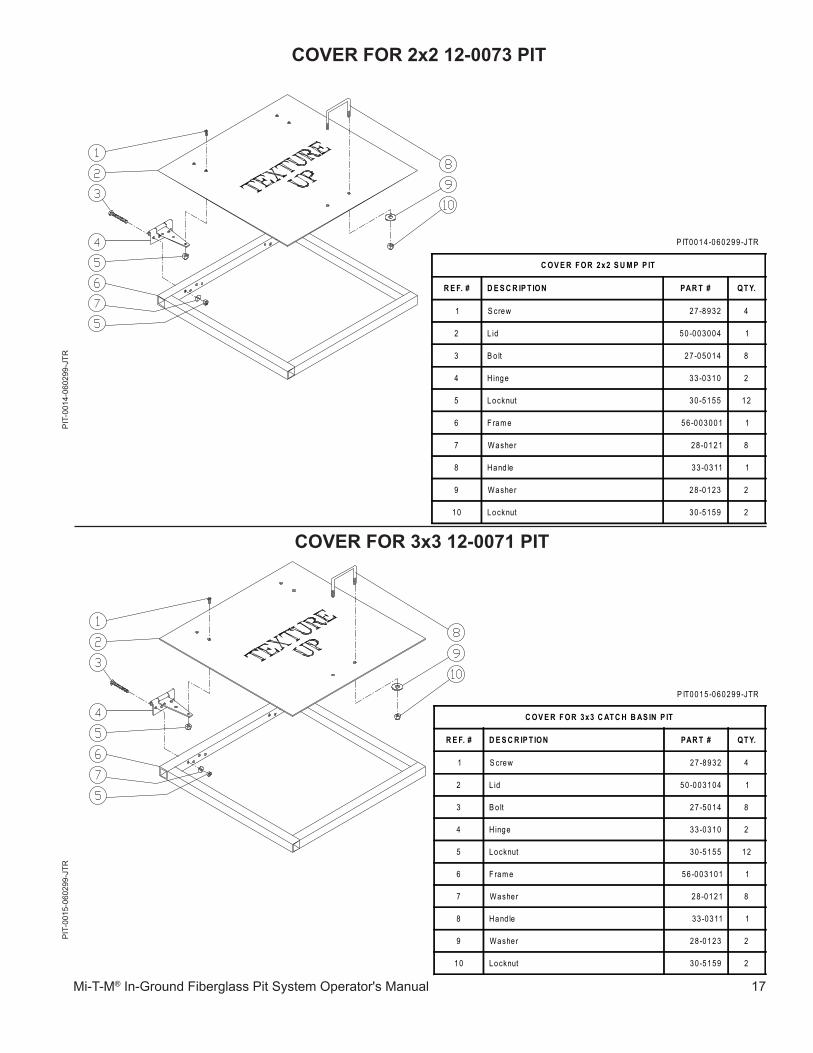
coVeR foR 2x2 12-0073 pitP
IT-0
0�5-
0602
99-j
TRP
IT-0
0�4-
0602
99-j
TR
coVeR foR 3x3 12-0071 pit
P IT0014 -060299-JTR
C OV E R F OR 2x2 S U M P P IT
R E F. # D E S C R IP T ION PAR T # QT Y.
1 S crew 27-8932 4
2 L id 50 -003004 1
3 B o lt 27 -05014 8
4 Hinge 33 -0310 2
5 Locknut 30 -5155 12
6 F ram e 56-003001 1
7 Washer 28 -0121 8
8 Hand le 33 -0311 1
9 Washer 28 -0123 2
10 Locknut 30 -5159 2
P IT0015 -060299-JTR
C OV E R F OR 3x3 C AT C H B AS IN P IT
R E F. # D E S C R IP T ION PAR T # QT Y.
1 S crew 27-8932 4
2 L id 50 -003104 1
3 B o lt 27 -5014 8
4 Hinge 33 -0310 2
5 Locknut 30 -5155 12
6 F ram e 56-003101 1
7 Washer 28 -0121 8
8 Hand le 33 -0311 1
9 Washer 28 -0123 2
10 Locknut 30 -5159 2

�8 Mi-T-M® In-Ground Fiberglass Pit System Operator's Manual
PIT
-00�
6-06
0299
-jTR
coVeR foR 3x9 12-0074 3-staGe coLLection pit
PIT0016-083106-PJH
COVER FOR 3x9 3-STAGE COLLECTION PIT
REF. # DESCRIPTION PART # QTY.
1 Lid-Small 56-03205 1
2 Lid-Large 56-03207 1
3 Handle 33-0311 3
4 Screw 27-8932 14
5 Lid-Medium 56-03206 1
6 Bolt 27-5014 28
7 Hinge 33-0310 7
8 Locknut 30-5155 42
9 Washer 28-0123 6
10 Locknut 30-5159 6
11 Washer 28-0121 28
12 Frame 56-003201 1
56-0
032
083�
06
Mi-T-M® In-Ground Fiberglass Pit System Operator's Manual �9
stateMent of WaRRantY
Mi-T-M warrants all parts (except those referred to below) of your new In-ground Fiberglass Pit System to be free from defects in materials and workmanship for one year from the date of original purchase.
Defective parts not subject to normal wear and tear will be repaired or replaced at Mi-T-M's option during the warranty period. In any event, reimbursement is limited to the purchase price paid.
eXcLUsions
�. normal wear parts: Seals Gaskets O-rings 2. Parts damaged due to: -normal wear, misapplication, modifications/alterations, abuse, -operation at other than recommended temperature, -the use of caustic liquids, -chloride corrosion or chemical deterioration, -fluctuations in water supply, -operating unit in an abrasive, corrosive or freezing environment.
3. Parts damaged by failure to follow recommended: -installation, operating and maintenance procedures.
4. This warranty does not cover the cost of: -normal maintenance or adjustments, -labor charges, -transportation charges to Service Center, -freight damage. 5. The use of other than genuine Mi-T-M parts will void warranty. Parts returned, prepaid to Mi-T-M's factory or to an authorized Service Center will be inspected and replaced free of charge if found to be defective and subject to warranty. There are no warranties which extend beyond the description of the face hereof. Under no circumstances shall Mi-T-M bear any responsibility for loss of use of the unit, loss of time or rental, inconvenience, commercial loss or consequential damages.

20 Mi-T-M® In-Ground Fiberglass Pit System Operator's Manual