installation manual - australian security...
TRANSCRIPT

PC5O15Version 2.3A
DLS-3 version 1.2 or laterWARNING This manual contains information on limitations regardingproduct use and function and information on the limitations as to liabilityof the manufacturer. The entire manual should be carefully read.
InstallationManual
WITH

LIMITED WARRANTYDigital Security Controls Ltd. warrants the original purchaser that for a period of twelvemonths from the date of purchase, the product shall be free of defects in materials andworkmanship under normal use. During the warranty period, Digital Security ControlsLtd. shall, at its option, repair or replace any defective product upon return of the productto its factory, at no charge for labour and materials. Any replacement and/or repairedparts are warranted for the remainder of the original warranty or ninety (90) days, which-ever is longer. The original owner must promptly notify Digital Security Controls Ltd. inwriting that there is defect in material or workmanship, such written notice to be receivedin all events prior to expiration of the warranty period.
International WarrantyThe warranty for international customers is the same as for any customer within Canadaand the United States, with the exception that Digital Security Controls Ltd. shall not beresponsible for any customs fees, taxes, or VAT that may be due.
Warranty ProcedureTo obtain service under this warranty, please return the item(s) in question to the point ofpurchase. All authorized distributors and dealers have a warranty program. Anyone re-turning goods to Digital Security Controls Ltd. must first obtain an authorization num-ber. Digital Security Controls Ltd. will not accept any shipment whatsoever for whichprior authorization has not been obtained.
Conditions to Void WarrantyThis warranty applies only to defects in parts and workmanship relating to normal use. Itdoes not cover:
• damage incurred in shipping or handling;
• damage caused by disaster such as fire, flood, wind, earthquake or lightning;
• damage due to causes beyond the control of Digital Security Controls Ltd. such asexcessive voltage, mechanical shock or water damage;
• damage caused by unauthorized attachment, alterations, modifications or foreign objects;
• damage caused by peripherals (unless such peripherals were supplied by Digital Secu-rity Controls Ltd.);
• defects caused by failure to provide a suitable installation environment for the prod-ucts;
• damage caused by use of the products for purposes other than those for which it wasdesigned;
• damage from improper maintenance;
• damage arising out of any other abuse, mishandling or improper application of theproducts.
Digital Security Controls Ltd.’s liability for failure to repair the product under this war-ranty after a reasonable number of attempts will be limited to a replacement of the prod-uct, as the exclusive remedy for breach of warranty. Under no circumstances shall DigitalSecurity Controls Ltd. be liable for any special, incidental, or consequential damagesbased upon breach of warranty, breach of contract, negligence, strict liability, or anyother legal theory. Such damages include, but are not limited to, loss of profits, loss ofthe product or any associated equipment, cost of capital, cost of substitute or replace-ment equipment, facilities or services, down time, purchaser’s time, the claims of thirdparties, including customers, and injury to property.
Disclaimer of WarrantiesThis warranty contains the entire warranty and shall be in lieu of any and all otherwarranties, whether expressed or implied (including all implied warranties of mer-chantability or fitness for a particular purpose) And of all other obligations or li-abilities on the part of Digital Security Controls Ltd. Digital Security Controls Ltd.neither assumes nor authorizes any other person purporting to act on its behalf tomodify or to change this warranty, nor to assume for it any other warranty or liabil-ity concerning this product.
This disclaimer of warranties and limited warranty are governed by the laws of theprovince of Ontario, Canada.
WARNING: Digital Security Controls Ltd. recommends that the entire system be com-pletely tested on a regular basis. However, despite frequent testing, and due to, but notlimited to, criminal tampering or electrical disruption, it is possible for this product tofail to perform as expected.
Installer’s LockoutAny products returned to DSC which have the Installer’s Lockout option enabled andexhibit no other problems will be subject to a service charge.
Out of Warranty RepairsDigital Security Controls Ltd. will at its option repair or replace out-of-warranty prod-ucts which are returned to its factory according to the following conditions. Anyonereturning goods to Digital Security Controls Ltd. must first obtain an authorization num-ber. Digital Security Controls Ltd. will not accept any shipment whatsoever for whichprior authorization has not been obtained.
Products which Digital Security Controls Ltd. determines to be repairable will be repairedand returned. A set fee which Digital Security Controls Ltd. has predetermined and whichmay be revised from time to time, will be charged for each unit repaired.
Products which Digital Security Controls Ltd. determines not to be repairable will bereplaced by the nearest equivalent product available at that time. The current marketprice of the replacement product will be charged for each replacement unit.
WARNING Please Read CarefullyNote to InstallersThis warning contains vital information. As the only individual in contact with system users, it is yourresponsibility to bring each item in this warning to the attention of the users of this system.
System FailuresThis system has been carefully designed to be as effective as possible. There are circumstances, how-ever, involving fire, burglary, or other types of emergencies where it may not provide protection. Anyalarm system of any type may be compromised deliberately or may fail to operate as expected for avariety of reasons. Some but not all of these reasons may be: Inadequate InstallationA security system must be installed properly in order to provide adequate protection. Every installationshould be evaluated by a security professional to ensure that all access points and areas are covered.Locks and latches on windows and doors must be secure and operate as intended. Windows, doors,walls, ceilings and other building materials must be of sufficient strength and construction to providethe level of protection expected. A reevaluation must be done during and after any construction activity.An evaluation by the fire and/or police department is highly recommended if this service is available. Criminal KnowledgeThis system contains security features which were known to be effective at the time of manufacture. It ispossible for persons with criminal intent to develop techniques which reduce the effectiveness of thesefeatures. It is important that a security system be reviewed periodically to ensure that its features remaineffective and that it be updated or replaced if it is found that it does not provide the protection expected. Access by IntrudersIntruders may enter through an unprotected access point, circumvent a sensing device, evade detectionby moving through an area of insufficient coverage, disconnect a warning device, or interfere with orprevent the proper operation of the system. Power FailureControl units, intrusion detectors, smoke detectors and many other security devices require an adequatepower supply for proper operation. If a device operates from batteries, it is possible for the batteries to fail.Even if the batteries have not failed, they must be charged, in good condition and installed correctly. If adevice operates only by AC power, any interruption, however brief, will render that device inoperativewhile it does not have power. Power interruptions of any length are often accompanied by voltage fluctua-tions which may damage electronic equipment such as a security system. After a power interruption hasoccurred, immediately conduct a complete system test to ensure that the system operates as intended. Failure of Replaceable BatteriesThis system’s wireless transmitters have been designed to provide several years of battery life under normalconditions. The expected battery life is a function of the device environment, usage and type. Ambient con-ditions such as high humidity, high or low temperatures, or large temperature fluctuations may reduce theexpected battery life. While each transmitting device has a low battery monitor which identifies when thebatteries need to be replaced, this monitor may fail to operate as expected. Regular testing and maintenancewill keep the system in good operating condition. Compromise of Radio Frequency (Wireless) DevicesSignals may not reach the receiver under all circumstances which could include metal objects placed on ornear the radio path or deliberate jamming or other inadvertent radio signal interference. System UsersA user may not be able to operate a panic or emergency switch possibly due to permanent or temporaryphysical disability, inability to reach the device in time, or unfamiliarity with the correct operation. It isimportant that all system users be trained in the correct operation of the alarm system and that theyknow how to respond when the system indicates an alarm. Smoke DetectorsSmoke detectors that are a part of this system may not properly alert occupants of a fire for a number ofreasons, some of which follow. The smoke detectors may have been improperly installed or positioned.Smoke may not be able to reach the smoke detectors, such as when the fire is in a chimney, walls or roofs,or on the other side of closed doors. Smoke detectors may not detect smoke from fires on another level ofthe residence or building.Every fire is different in the amount of smoke produced and the rate of burning. Smoke detectors cannotsense all types of fires equally well. Smoke detectors may not provide timely warning of fires caused bycarelessness or safety hazards such as smoking in bed, violent explosions, escaping gas, improper storageof flammable materials, overloaded electrical circuits, children playing with matches or arson.Even if the smoke detector operates as intended, there may be circumstances when there is insufficientwarning to allow all occupants to escape in time to avoid injury or death. Motion DetectorsMotion detectors can only detect motion within the designated areas as shown in their respective installa-tion instructions. They cannot discriminate between intruders and intended occupants. Motion detectors donot provide volumetric area protection. They have multiple beams of detection and motion can only bedetected in unobstructed areas covered by these beams. They cannot detect motion which occurs behindwalls, ceilings, floor, closed doors, glass partitions, glass doors or windows. Any type of tampering whetherintentional or unintentional such as masking, painting, or spraying of any material on the lenses, mirrors,windows or any other part of the detection system will impair its proper operation.Passive infrared motion detectors operate by sensing changes in temperature. However their effective-ness can be reduced when the ambient temperature rises near or above body temperature or if there areintentional or unintentional sources of heat in or near the detection area. Some of these heat sourcescould be heaters, radiators, stoves, barbeques, fireplaces, sunlight, steam vents, lighting and so on. Warning DevicesWarning devices such as sirens, bells, horns, or strobes may not warn people or waken someone sleeping if thereis an intervening wall or door. If warning devices are located on a different level of the residence or premise, thenit is less likely that the occupants will be alerted or awakened. Audible warning devices may be interfered withby other noise sources such as stereos, radios, televisions, air conditioners or other appliances, or passing traffic.Audible warning devices, however loud, may not be heard by a hearing-impaired person. Telephone LinesIf telephone lines are used to transmit alarms, they may be out of service or busy for certain periods oftime. Also an intruder may cut the telephone line or defeat its operation by more sophisticated meanswhich may be difficult to detect. Insufficient TimeThere may be circumstances when the system will operate as intended, yet the occupants will not beprotected from the emergency due to their inability to respond to the warnings in a timely manner. If thesystem is monitored, the response may not occur in time to protect the occupants or their belongings. Component FailureAlthough every effort has been made to make this system as reliable as possible, the system may fail tofunction as intended due to the failure of a component. Inadequate TestingMost problems that would prevent an alarm system from operating as intended can be found by regulartesting and maintenance. The complete system should be tested weekly and immediately after a break-in, an attempted break-in, a fire, a storm, an earthquake, an accident, or any kind of construction activityinside or outside the premises. The testing should include all sensing devices, keypads, consoles, alarmindicating devices and any other operational devices that are part of the system. Security and InsuranceRegardless of its capabilities, an alarm system is not a substitute for property or life insurance. An alarmsystem also is not a substitute for property owners, renters, or other occupants to act prudently to preventor minimize the harmful effects of an emergency situation.

Table of Contents
System Introduction 11.1 PC5015 Specifications ......................................................... 11.2 Additional Devices ............................................................... 21.3 Out of the Box ...................................................................... 4
Getting Started 52.1 Installation Steps .................................................................. 52.2 Terminal Descriptions .......................................................... 62.3 Keybus Operation and Wiring ............................................. 72.4 Current Ratings - Modules and Accessories ...................... 72.5 Assigning Zones to Zone Expanders .................................. 82.6 Keypad Assignment ............................................................. 92.7 Enable Supervision .............................................................. 92.8 Removing Modules ............................................................ 102.9 Zone Wiring ........................................................................ 102.10 Keypad Zones .................................................................... 12
Keypad Commands 133.1 Access Codes .................................................................... 133.2 Arming/Disarming .............................................................. 143.3 Auto Bypass ....................................................................... 143.4 [*] Commands .................................................................... 143.5 Function Keys .................................................................... 173.6 Global and Partition Keypad Operation ............................ 193.7 Features Available for the LCD5500Z ............................... 20
How to Program 214.1 How to Enter Installer Programming .................................. 214.2 Programming Decimal Data ............................................... 214.3 Programming HEX Data ..................................................... 214.4 Programming Toggle Option Sections ............................... 224.5 Viewing Programming ........................................................ 22
Program Descriptions 235.1 Zone Definitions ................................................................. 235.2 Zone Attributes ................................................................... 245.3 Communicator - Dialing ..................................................... 255.4 Communicator - Phone Numbers ...................................... 255.5 Communicator - Account Numbers ................................... 265.6 Communicator - Reporting Formats .................................. 265.7 Communicator – Reporting Codes .................................... 285.8 Downloading ...................................................................... 295.9 Partitions/Zone Assignment ............................................... 305.10 Programmable Outputs ...................................................... 305.11 Telephone Line Monitor (TLM) ........................................... 335.12 Siren .................................................................................... 335.13 Test Transmission ............................................................... 335.14 Fire, Auxiliary, Panic Keys ................................................. 345.15 Entry/Exit Delay Options .................................................... 345.16 Event Buffer ........................................................................ 355.17 Swinger Shutdown ............................................................. 355.18 Daylight Savings Time ....................................................... 355.19 Keypad Backlighting .......................................................... 355.20 Arming/Disarming Options ................................................ 355.21 Automatic Arming .............................................................. 365.22 Keypad Lockout ................................................................. 375.23 Keypad Blanking ................................................................ 375.24 Loop Response .................................................................. 375.25 Keypad Tampers ................................................................ 375.26 LINKS1000 Cellular Communicator ................................... 385.27 Module Programming ......................................................... 385.28 Default (Factory) ................................................................ 395.29 Installer Lockout ................................................................. 395.30 Walk Test (Installer) ............................................................ 395.31 International Programming ................................................ 40
Appendix A: Reporting Codes 42
Appendix B: Zone Reporting Codes 44
Appendix C: Control Panel Wiring Diagram 45
Appendix D: Modules Supportedon the PC5015 v2.3A 46
Limited Warranty inside back cover

1
System IntroductionS E C T I O N 1
1.1 PC5015 SpecificationsFlexible Zone Configuration:• 8 Fully Programmable Zones• 38 Access Codes: 32 User, 1 System Master, 2 Partition Master, 2 Duress and 1 maintenance• Expandable to 32 Zones• Keypads with zone inputs available (PC5508Z, PC5516Z, PC5532Z, LCD5500Z)• Hardwired expansion available using the PC5108 Eight Zone Expansion Module and the PC5700 Fire
Module• Wireless expansion available using the PC5132 Wireless Zone Expansion Module (up to 32 wireless
zones, 900MHz, True Spread Spectrum Technology, Fully Supervised)• Normally Closed, Single EOL, or Double EOL zone supervision• 28 Zone Types, 8 Programmable Zone Options• 2 Partitions
Audible Alarm Output:• 700mA Supervised Bell Output (current limited at 3 amps), 12 VDC
• Steady or Pulsed Output
EEPROM Memory:• Will not lose programming or system status on complete AC and Battery failure
Programmable Outputs:• Up to 14 Programmable Voltage Outputs, 24 programmable options• One Low Current (50 mA) PGM output on main panel• One High Current (300 mA) PGM output on main panel• Eight Additional Low Current (50 mA) PGM outputs available using the PC5208 module• Four High Current (1 Amp) PGM outputs Available Using the PC5204 module• 1 PC5204 Output Fully Supervised for Siren Output
Powerful 1.5 Amp Regulated Power Supply:• 550 mA Auxiliary Supply, 12 VDC
• Positive Temperature Coefficient (PTC) components replace fuses• Supervision for loss of AC Power, Low Battery• Internal Clock Locked to AC Power Frequency
Power Requirements:• Transformer = 16.5 VAC, 1.5A• Battery = 12 volt 4 Ah minimum rechargeable sealed lead acid
Remote Keypad Specifications:• 8 Different Keypads Available:
- PC5508 (Z) 8 Zone LED Keypad - PC5532(Z) 32 Zone LED Keypad- PC5516 (Z) 16 Zone LED Keypad - LCD5500 (Z) Alphanumeric Keypad
• Each Keypad has 5 Fully Programmable Function Keys • Connect up to 8 Keypads• Four Wire (Quad) Connection to Keybus • Built in Piezoelectric Buzzer• “Z” version keypads have zone input
Digital Communicator Specifications:• Supports all Major Formats including SIA and Contact ID and Residential Dial• Split Reporting of Selected Transmissions to Each Telephone Number• 3 Programmable Phone Numbers • 2 Account numbers• Supports LINKS1000 Cellular Communication • DTMF and Pulse Dialing• DPDT Line Seizure • Anti-jam Feature• Event-Initiated Personal Paging
System Supervision FeaturesThe PC5015 continuously monitors a number of possible trouble conditions including:• AC Power Failure • Trouble by Zone • Fire Trouble• Telephone Line Trouble • Low Battery Condition • Bell Output Trouble• Loss of Internal Clock • AUX Power Supply Fault • Tamper by Zone• Failure to Communicate • Module Fault (Supervisory or Tamper) • Camera Troubles via DLM-4L

2
S Y S T E M I N T R O D U C T I O N
False Alarm Prevention Features• Audible Exit Delay • Audible Exit Fault •Urgency on Entry Delay• Quick Exit • Swinger Shutdown • Recent Closing Transmission• Cross Zone Alarm • Burglary-verified timer •Double Hit Timer• Communication Delay • Rotating Keypress Buffer
Additional Features• Auto Arm by Partition at Specified Time each day of the week• Keypad Activated Alarm Output and Communicator Test• Keypad Lockout• Audio Capability using the PC5928 Audio Interface Module which allows local intercom and Central
Station 2-Way Listen in.• All modules connect to the system via a four wire Keybus up to 1000’/305m from main panel• Event Buffer can be printed using PC5400 RS232 Serial Interface module• Supports the Escort5580 Voice Prompt Module with Automation/Lighting Control• 128 Event Buffer, Time and Date Stamped• Upload/Download Capability• Daylight Savings time option• Downlook support (DLM-4L v1.0L and PC5108L)
1.2 Additional DevicesIn addition to the information below, see the back cover for a DSC Module Compatability table.
1.2.1 KeypadsA maximum of eight (8) keypads can be connected to the control panel and can be any combination ofthe following listed. Different keypads (with function keys) can be used for different size systems; 8 zone,16 zone and 32 zone.
PC5508/PC5508Z PC5516 /PC5516Z PC5532/PC5532Z LCD5500/LCD5500Z8 zone LED keypad 16 zone LED keypad 32 zone LED keypad LCD keypad
1.2.2 PC5108 Eight Zone Expander ModuleEight zone expander module can be used to increase the number of zones onthe system. Up to 3 modules can be connected to increase the system zones toa maximum of 32. (See PC5108 Installation Instructions Sheet.)
1.2.3 PC5132 Wireless Receiver ModuleThe PC5132 Wireless Receiver module can be used to connect up to 32wireless devices. All devices are spread spectrum, 900 MHz, fully supervisedand use standard ‘AAA’ or ‘AA’ alkaline batteries. (See PC5132 InstallationManual for details.)
Additional wireless devices are available:
WLS904 Wireless Motion DetectorThe wireless Motion Detector can be used in conjunction with the PC5132 Wireless Receiver to includewireless space protection. The unit comes with four ‘AAA’ batteries.
WLS906 Wireless Smoke DetectorThe wireless Smoke Detector can be used in conjunction with the PC5132 Wireless Receiver to includewireless smoke detection. The unit comes with six ‘AA’ batteries.
WLS907 Wireless Slimline Universal TransmitterThe wireless Slimline Universal Transmitter can be used with the PC5132 Wireless Receiver to add wireless dooror window contacts in a smaller package. The unit comes with three ‘AAA’ batteries and has built-in contacts.
WLS908 Wireless Panic PendantThe wireless Panic Pendant can be used in conjunction with the PC5132 Wireless Receiver to includepersonal wireless protection. The unit comes with 1 mini 12V battery (not user changeable).

3
S Y S T E M I N T R O D U C T I O N
WLS909 Wireless KeyThe Wireless Key can be used in conjunction with the PC5132 Wireless Receiver to include a simple andmobile method of arming and disarming the system. The unit comes with three Photo/Electronic 1.5V batteries.This system can have a maximum of 16 Wireless Keys.
WLS910 Wireless Handheld KeypadThe wireless Handheld Keypad can be used in conjunction with the PC5132 Wireless Receiver to include asimple and mobile method of arming and disarming the system. The unit comes with three ‘AAA’ batteries.The system can have a maximum of four wireless Handheld Keypads.
1.2.4 PC5204 Power Supply Output ModuleThe PC5204 can provide up to 1 Amp of additional power for modules ordevices connected to the control panel. The module requires a 16.5 volt AC 40VA transformer and 4 AH battery. In addition, the module provides 4 program-mable high current voltage outputs. (See PC5204 Installation Instructions fordetails.)
1.2.5 PC5208 Eight Low Current Output ModuleAdds eight programmable low current outputs (50 mA) to the control. (SeePC5208 Installation Instructions for details.)
1.2.6 Escort5580 ModuleThis Escort5580 module will turn any touch tone phone into a fully functionalkeypad. The module also includes a built-in interface to control up to 32 linecarrier type devices for lighting and temperature control (See Escort5580Installation Manual for details.)
1.2.7 PC5928 Audio Interface ModuleThe PC5928 Audio Interface module is a simple way to incorporate paging,intercom, baby listen-in and door answer to the PC5015 control panel. Themodule also has built-in two-way voice capability for central station (SeePC5928 Installation Manual for details).
Three additional devices are available:
PC5921 Intercom Audio StationPC5921 Intercom Audio StationPC5921 Intercom Audio StationPC5921 Intercom Audio StationPC5921 Intercom Audio Station can be used in conjunction with the PC5928 Audio InterfaceModule.PC5921 EXT Door Box Audio StationPC5921 EXT Door Box Audio StationPC5921 EXT Door Box Audio StationPC5921 EXT Door Box Audio StationPC5921 EXT Door Box Audio Station can be used in conjunction with the PC5928 AudioInterface Module.PC5921 EXT/R Door Box Audio StationPC5921 EXT/R Door Box Audio StationPC5921 EXT/R Door Box Audio StationPC5921 EXT/R Door Box Audio StationPC5921 EXT/R Door Box Audio Station can be used in conjunction with the PC5928 AudioInterface Module. The Door Box contains a relay so the normal door bell can be used instead ofthe internal one generated by the PC5928 module.
1.2.8 PC5400 Printer ModuleThis PC5400 Printer Module will allow the panel to print out all events thatoccur on the system to any serial printer. All events will be printed withthe Partition, time, date and the event that occurred. (See PC5400 Installa-tion Manual for details.)
1.2.9 LINKS1000 Cellular CommunicatorThe LINKS1000 Cellular Communicator provides an efficient, cost-effectivemethod for adding cellular back up. The unit comes in its own cabinet withantenna and requires a separate battery and transformer (See Section 5.26“LINKS1000 Cellular Communicator”).

4
S Y S T E M I N T R O D U C T I O N
1.2.10 Downlook Support: PC5108L and DLM-4L v1.0LThe PC5108L will expand the control panel’s zone capability by adding eight fully programmable zoneinputs. The module will also act as an interface between the DLM-4L v1.0L Video Transmission moduleand the PC5015 v2.2 alarm control panel. The PC5108L is also an 8-camera video switcher.For more information on either module, see their respective installation manuals.
PC5108L DLM-4L v1.0L
1.2.11 PC5700 Fire ModuleThis is a zone expansion module with four general purpose zone inputs, twoClass A supervisory waterflow zone inputs, ground fault detection and dual-supervised telephone line inputs.
1.2.12 CabinetsSeveral different cabinets are available for the PC5015 modules. They are as follows:PC5003C Main Control Cabinet for the PC5015 main panel. Dimensions 288mm x 298mm x 78mm /11.3” x 11.7” x 3” approximately.PC5002C Cabinet to house the PC5204 Power Supply Output Module. Dimensions 213mm x 235mm x78mm / 8.4” x 9.25” x 3” approximately.PC5004C Cabinet to house the Escort5580 Module and PC5400 Printer Module. Dimensions 229mm x178mm x 65mm / 9” x 7” x 2.6” approximately.PC5001C Cabinet to house the PC5108 Zone Expander Module and the PC5208 Eight Low CurrentOutput Module. Dimensions 153mm x 122mm x 38mm / 6” x 4.8” x 1.5” approximately.PC5001CP Plastic Cabinet to house the PC5108 Zone Expander Module and the PC5208 Eight LowCurrent Output Module. Dimensions 146mm x 105mm x 25.5mm / 5.75” x 4.2” x 1” approximately.
1.2.13 BackplatesThere are two different backplates available for keypads to locate an Audio Station next to the keypad:
PC55BP1 BackplateThis backplate is to be used when an Audio Station is to be located next toa keypad. Dimensions 208mm x 115mm x 18mm / 8.2” x 4.5” x 0.25”approximately.
PC55BP2 BackplateThis backplate is to be used when an Audio Station is to be located next to akeypad. In addition the backplate will allow you to mount a PC5108 ZoneExpander Module or the PC5208 Eight Low Current Output Module. Dimensions208mm x 115mm x 18mm / 8.2” x 4.5” x 0.7” approximately.
1.3 Out of the BoxVerify that the following equipment is included in your system:• one PC5015 main control cabinet• one PC5015 circuit board• one PC55XX(Z) / LCD5500(Z) keypad• one set of manuals (Installation Manual, one Programming Worksheet Manual and one Instruction
Manual for the end user• one hardware pack consisting of:
- five plastic circuit board standoffs- seventeen 5600 ohm (5.6K) resistors- one 2200 ohm (2.2K) resistor- one 1000 ohm (1K) resistor

5
Getting StartedS E C T I O N 2
The following sections provide a complete description of how to wire and configure devices and zones.
2.1 Installation StepsThe following steps are provided to assist with the installation of the panel. It is suggested that you read over thissection briefly to get an overall understanding of the order of installation. Once this is done carefully work througheach step. Working from this plan will help reduce problems and reduce the overall installation time required.
Step 1 Create a LayoutDraw a rough sketch of the building and include all alarm detection devices, zone expanders, keypadsand all other modules that are required.
Step 2 Mounting the PanelLocate the panel in a dry area, preferably located near an unswitched AC power source and the incomingtelephone line. Before attaching the cabinet to the wall be sure to press the five circuit boardmounting studs into the cabinet from the back.
Complete all wiring before applying AC or connecting the battery.
Step 3 Wiring the Keybus (Section 2.3)Wire the Keybus to each of the modules following the guidelines provided.
Step 4 Assigning Zones to Zone Expanders (Section 2.5)If zone expander modules are being used the modules must be configured so the panel knows whichzones are assigned to each expander. Follow the guideline provided to assign zones to expanders.
Step 5 Zone Wiring (Section 2.9)Power down the control panel and complete all zone wiring. Follow the guidelines provided in Section 2.9to connect zones using normally closed loops, single EOL resistor, double EOL resistors, Fire zones andKeyswitch Arming zones.
Step 6 Completing WiringComplete all other wiring including bells or sirens, phone line connections, ground connections or anyother wiring necessary. Follow the guidelines provided in Section 2.2 “Terminal Descriptions”.
Step 7 Power up the Control PanelOnce all zone wiring and Keybus wiring is complete, power up the control panel.
The panel will not power up if only the battery is connected.
Step 8 Keypad Assignment (Section 2.6)Keypads must be assigned to different slots to be properly supervised. Follow the guideline provided inSection 2.6 to assign keypads.
Step 9 Enabling Supervision (Section 2.7)After all modules have been wired to the Keybus, supervision must be enabled. Once supervision is enabled,the panel will be able to indicate module communication faults. Follow the guidelines provided in Section 2.7.
Step 10 Programming the System (Sections 4 and 5)Section 4.0 provides a complete description of how to program the panel. Section 5.0 contains completedescriptions of the various programmable features, what options are available and how the options function.The Programming Work Sheets should be filled out completely before attempting to program the system.
Step 11 Testing the SystemTest the panel completely to ensure that all features and functions are operating as programmed.

6
G E T T I N G S T A R T E D
2.2 Terminal DescriptionsAC Terminals - ACThe panel requires a 16.5 volt, 1.5A transformer. Connect the transformer to an unswitched AC sourceand connect the transformer to these terminals.
Do not connect the transformer until all other wiring is complete.
Battery ConnectionThe battery is used to provide back up power in the event of an AC power failure and to provideadditional current when the panel demands exceed the power output of the transformer, such as whenthe panel is in alarm.
Do not connect the battery until all other wiring is complete.Connect the RED battery lead to the positive of the battery, the BLACK battery lead to the negative.
Auxiliary Power Terminals - AUX+ and GNDThese terminals provide up to 550 mA of additional current at 12 VDC (rated 11.6 -12.6 VDC for ULresidential applications) for devices requiring power. Connect the positive side of any device requiringpower to the AUX+ terminal, the negative side to GND. The AUX output is protected; if too much current isdrawn from these terminals (wiring short) the panel will temporarily shut off the output, until the problem iscorrected.
Bell Output Terminals - BELL+ and BELL-These terminals provide up to 3 Amps of current at 12 VDC (rated 11.6 -12.6 VDC for UL residentialapplications) (with stand-by battery; 700 mA continuous) for powering bells, sirens, strobes or otherwarning type equipment. Connect the positive side of any alarm warning device to BELL+, the negativeside to BELL–. The BELL output is protected; if too much current is drawn from these terminals (wiringshort) the BELL PTC will open.The Bell output is supervised. If no alarm warning device is being used connect a 1000 ohm resistoracross BELL+ and BELL– to prevent the panel from displaying a trouble condition (See Section 3.4 “[ ]Commands, [ ][2]”).
Keybus Terminals - RED, BLK, YEL, GRNThe Keybus is used by the panel to communicate with modules and by modules to communicate with thepanel. Each module has four Keybus terminals that must be connected to the four Keybus terminals onthe panel. For more information, see Section 2.3 “Keybus Operation and Wiring”.
Programmable Outputs - PGM1 and PGM2Each PGM output is an open collector switch to ground. That is, when the PGMoutput is activated by the panel the terminal will switch to ground.PGM1 can sink up to 50 mA of current. PGMs can be used to activate LEDs ora small buzzer. Connect the positive side of the LED or buzzer to AUX+, thenegative side to the PGM1.PGM2 is a high current output (300mA) and operates similar to PGM1. TheCON1 must remain on at all times. If more than 300 mA of current is required arelay must be used. Refer to the diagram.
Zone Input Terminals - Z1 to Z8Each detection device must be connected to a zone on the control panel. It is suggested that each zonehave one detection device however it is possible to wire multiple detection devices to the same zone.For zone wiring specifics, see Section 2.9 “Zone Wiring” .
Telephone Connection Terminals - TIP, RING, T-1, R-1If a telephone line is required for central station communication or downloading, connect an RJ-31X jackin the following manner:
• RING - Red Wire _______ Incoming line from• TIP - Green Wire telephone company
• R-1 - Grey Wire ________ Outgoing line to• T-1 - Brown Wire house telephone(s)

7
G E T T I N G S T A R T E D
Connect the PC5015 and modules that use the telephone line(s) in the following order:
For example, if you are installing a PC5015 with a LINKS1000 and a PC5928 Intercom module, connectthe incoming line to the LINKS1000, then from the LINKS1000 to the PC5015, then from the PC5015 to thePC5928 Intercom and then from the PC5928 to the house telephones
For proper operation there must be no other telephone equipment connected between the controlpanel and the telephone company facilities.Do not connect the alarm panel communicator to telephone lines intended for use with a FAX ma-chine. These lines may incorporate a voice filter which disconnects the line if anything other than FAXsignals are detected, resulting in incomplete transmissions.
2.3 Keybus Operation and WiringThe Keybus is used by the panel to communicate with all modules connected and by the modules to talk tothe panel. The RED and BLK terminals are used to provide power while YEL and GRN are clock and data.
The 4 Keybus terminals of the panel must be connected to the 4 Keybus terminals or wires of all modules.
The following conditions apply:• Keybus should be run in minimum 22 gauge quad (0.5mm), two pair twist preferred• the modules can be home run to the panel, connected in series or can be T-tapped• any module can be connected anywhere along the Keybus, you do not need a separate Keybus wire
run for keypads, zone expanders etc.• no module can be more than 1,000'/305m (in wire length) from the panel• shielded wire is not necessary unless wires are run in an area that may present excessive RF noise or
interferenceExample of Keybus Wiring
B
C
APANEL500’
500’
150’
150’
B
C
APANEL500’
500’
150’
150’
NOTE: Module (A) is wired correctly as it is within 1,000'/305m of thepanel, in wire distance.Module (B) is wired correctly as it is within 1,000'/305m of thepanel, in wire distanceModule (C) is NOT wired correctly as it is further than 1,000'/305m from the panel, in wire distance.
2.4 Current Ratings - Modules and AccessoriesIn order for the Power 832 system to operate properly, the power output capabilities of the main controland expansion devices must not be exceeded. Use the data presented below to ensure that no part ofthe system is overloaded and cannot function properly.
System Outputs (all 12 VDC)• PC5015 VAUX: 550 mA. Subtract the listed rating for each keypad, expansion module and accessory
connected to VAUX or Keybus.BELL: 700 mA. Continuous Rating.
3.0 A. Short Term. Available only with stand-by battery connected.• PC5204 VAUX: 1.0 A. Continuous Rating. Subtract for each device connected.
3.0 A. Short Term. Available only with stand-by battery connected.• PC5208 VAUX: 250 mA. Subtract for each device connected. Subtract the total load on this terminal
from the PC5015 VAUX/Keybus output.• PC5108 VAUX: 100 mA. Subtract for each device connected. Subtract the total load on this terminal
from the PC5015 VAUX/Keybus output.
LLLLL

8
G E T T I N G S T A R T E D
PC5015 Device Ratings (@ 12 VDC)• LCD5500 Keypad: 50 mA • PC5208 Output Module: 50 mA• PC5532 Keypad: 45 mA • PC5132 Wireless Module: 125 mA• PC5516 Keypad: 45 mA • Escort5580 Module: 150 mA• PC5508 Keypad: 45 mA • PC5928 Audio Interface Module: 65 mA• LCD5500Z Keypad: 85 mA • PC5921 Intercom Audio Station: 20 mA• PC5532Z Keypad: 85 mA • PC5921 EXT Door Box Audio Station: 20 mA• PC5516Z Keypad: 85 mA • PC5921 EXT/R Door Box Audio Station: 35 mA• PC5508Z Keypad: 85 mA • PC5400 Printer Module: 65 mA• PC5108 Zone Module: 35 mA • DLM-4L v1.0L: 180 mA• PC5204 Output Module: 20 mA • PC5700 Fire Module: 150 mA• PC5108L Downlook Interface: 60 mA
Other DevicesRead the manufacturer’s literature carefully to determine the maximum current requirement (duringactivation or alarm) and use this value for loading calculations. Do not allow connected devices to exceedthe system capabilities during any possible operational mode.
2.5 Assigning Zones to Zone ExpandersThe main panel contains zones 1 to 8. Additional zone expanders may be added to increase the numberof zones on the system. Each zone expander consists of two groups of 4 zones and each group must beconfigured to assign the specific zones to the expander. This is done by setting the jumpers located onthe expander to the proper settings.
Before a zone expander will work properly the jumpers must be set so the panel can determine thecorrect zone assignment.
The following are the jumper settings for different zone assignments:Jumpers System Zones Assigned
J1/J4 J2/J5 J3/J6ON ON ON Zones disabledOFF ON ON Zones disabledON OFF ON Zones 09 - 12OFF OFF ON Zones 13 - 16ON ON OFF Zones 17 - 20OFF ON OFF Zones 21 - 24ON OFF OFF Zones 25 - 28OFF OFF OFF Zones 29 - 32
J1, J2 and J3 set system zone assignments for expander zones 1-4J4, J5 and J6 set system zone assignments for expander zones 5-8
The following are diagrams of the PC5108 and PC5700 zone expander modules and where the jumperswitches are located. Refer to the Installation Instructions of each module for more information.
There are two sets of jumpers, one set for the first 4 zones of the expander and one set for the other 4 zones.
In these two diagrams the jumpers settings shown indicate the first group of four zones of the expanderwill be zones 9 to 12 and the second group of 4 zones will be 13 to 16. A group of zones can be disabledif they are not required for the installation.

9
G E T T I N G S T A R T E D
2.6 Keypad AssignmentThere are 8 available slots for keypads. LED keypads by default are assigned to slot 1 while theLCD5500(Z) is assigned by default to slot 8. Keypads can each be assigned to a different slot (1 to 8)which offers two advantages. The panel can supervise the keypad connection to indicate a troublecondition if it is removed. Also keypads can be assigned to operate a specific partition or operate as aglobal keypad.
2.6.1 How to Assign KeypadsAll keypad assignment must be done at each keypad on the system. When using LCD5500(Z) keypads,one keypad must remain in slot 8. Do not assign more than one keypad to the same slot.
To assign a keypad to a slot and select the partition it will operate, enter the following:Step 1 — Enter Installer ProgrammingStep 2 — Press [000] for Keypad ProgrammingStep 3 — Press [0] for Partition and Slot AssignmentEnter a two digit number to specify the partition and slot assignment.
1st digit Enter 0 for Global Keypad;Enter 1 for Partition 1 Keypad;Enter 2 for Partition 2 Keypad
2nd digit Enter 1 to 8 for Slot AssignmentPress the [#] key twice to exit programming. Continue this procedure at each keypad until all have beenassigned to the correct slot.
02.6.2 How to Program Function KeysEach of the 5 Function Keys on each keypad may be programmed for different operation on each keypad.
Step 1 - Enter Installer Programming.Step 2 - Press [000] for Keypad Programming.Step 3 - Enter [1] to [5] to select Function Key to program.Step 4 - Enter the 2 digit number, [00] to [25] for option.Step 5 - Continue from Step 3 until all Function Keys are programmed.Step 6 - Press [#] key twice to exit Installer Programming.
For a complete list of Function Key options See Section 3.5.1 “Function Key Options” .
2.7 Enable SupervisionOnce all the Keybus connections have been made, supervision must be enabled so the panel canindicate a trouble if a module is removed from the system.To enable supervision, enter the following at any keypad:
Step 1 - Press [ ] [8] [Installer Code] to enter Installer Programming.Step 2 - Press [902] to enable supervision. The panel will automatically search for all modules on the
system. Once the search (it will take about 1 minute) is complete enter the following to confirmthe modules on the system.
Step 3 - Press [903] to display all modules.Zone lights will be turned on according to what modules the panel has found on the system. The LCDkeypad will allow you to scroll through the modules. Refer to the following chart:
Light [1] ....... Keypad 1 present Light [13] ....... Zones 25 to 28 presentLight [2] ....... Keypad 2 present Light [14] ....... Zones 29 to 32 presentLight [3] ....... Keypad 3 present Light [15] ....... N/A (not used)Light [4] ....... Keypad 4 present Light [16] ....... N/A (not used)Light [5] ....... Keypad 5 present Light [17] ....... Module PC5132 presentLight [6] ....... Keypad 6 present Light [18] ....... Module PC5208 presentLight [7] ....... Keypad 7 present Light [19] ....... Module PC5204 presentLight [8] ....... Keypad 8 present Light [20] ....... Module PC5400 presentLight [9] ....... Zones 9 to 12 present Light [21] ....... Module PC5928 presentLight [10] ....... Zones 13 to 16 present Light [22] ....... Alternate Communicator presentLight [11] ....... Zones 17 to 20 present Light [23] ....... DLM-4L v1.0L presentLight [12] ....... Zones 21 to 24 present Light [24] ....... Escort5580 module present
If a module is connected but does not show as being present, it may be due to any of the following reasons:• it is not connected to the Keybus• if there is a Keybus wiring problem• if the module is more than 1,000'/305m from the panel• if the module does not have enough power• if the PC5132 does not have any devices added
10
G E T T I N G S T A R T E D
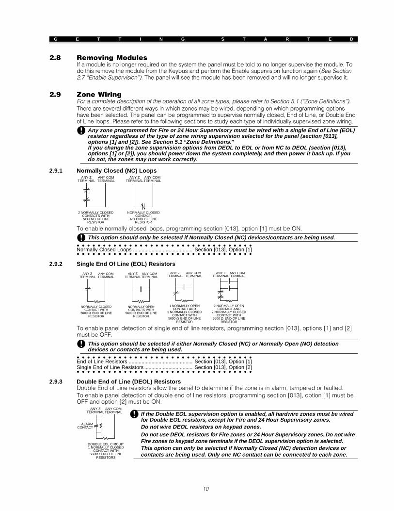
2.8 Removing ModulesIf a module is no longer required on the system the panel must be told to no longer supervise the module. Todo this remove the module from the Keybus and perform the Enable supervision function again (See Section2.7 “Enable Supervision”). The panel will see the module has been removed and will no longer supervise it.
2.9 Zone WiringFor a complete description of the operation of all zone types, please refer to Section 5.1 (“Zone Definitions”).There are several different ways in which zones may be wired, depending on which programming optionshave been selected. The panel can be programmed to supervise normally closed, End of Line, or Double Endof Line loops. Please refer to the following sections to study each type of individually supervised zone wiring.
Any zone programmed for Fire or 24 Hour Supervisory must be wired with a single End of Line (EOL)resistor regardless of the type of zone wiring supervision selected for the panel (section [013],options [1] and [2]). See Section 5.1 “Zone Definitions.”If you change the zone supervision options from DEOL to EOL or from NC to DEOL (section [013],options [1] or [2]), you should power down the system completely, and then power it back up. If youdo not, the zones may not work correctly.
2.9.1 Normally Closed (NC) Loops
2 NORMALLY CLOSEDCONTACTS WITHNO END OF LINE
RESISTOR
ANY ZTERMINAL
ANY COMTERMINAL
NORMALLY CLOSEDCONTACT;
NO END OF LINERESISTOR
ANY ZTERMINAL
ANY COMTERMINAL
To enable normally closed loops, programming section [013], option [1] must be ON.
This option should only be selected if Normally Closed (NC) devices/contacts are being used.
Normally Closed Loops .......................................... Section [013], Option [1]
2.9.2 Single End Of Line (EOL) Resistors
NORMALLY CLOSEDCONTACT WITH
5600 Ω END OF LINERESISTOR
ANY ZTERMINAL
ANY COMTERMINAL
NORMALLY OPENCONTACTS WITH
5600 Ω END OF LINERESISTOR
ANY ZTERMINAL
ANY COMTERMINAL
ANY ZTERMINAL
ANY COMTERMINAL
2 NORMALLY OPENCONTACT AND
2 NORMALLY CLOSEDCONTACT WITH
5600 Ω END OF LINERESISTOR
1 NORMALLY OPENCONTACT AND
1 NORMALLY CLOSEDCONTACT WITH
5600 Ω END OF LINERESISTOR
ANY ZTERMINAL
ANY COMTERMINAL
To enable panel detection of single end of line resistors, programming section [013], options [1] and [2]must be OFF.
This option should be selected if either Normally Closed (NC) or Normally Open (NO) detectiondevices or contacts are being used.
End of Line Resistors ............................................. Section [013], Option [1]
Single End of Line Resistors .................................. Section [013], Option [2]
2.9.3 Double End of Line (DEOL) ResistorsDouble End of Line resistors allow the panel to determine if the zone is in alarm, tampered or faulted.To enable panel detection of double end of line resistors, programming section [013], option [1] must beOFF and option [2] must be ON.
ANY ZTERMINAL
ANY COMTERMINAL
ALARMCONTACT
DOUBLE EOL CIRCUIT1 NORMALLY CLOSED
CONTACT WITH5600Ω END OF LINE
RESISTORS
If the Double EOL supervision option is enabled, all hardwire zones must be wiredfor Double EOL resistors, except for Fire and 24 Hour Supervisory zones.Do not wire DEOL resistors on keypad zones.Do not use DEOL resistors for Fire zones or 24 Hour Supervisory zones. Do not wireFire zones to keypad zone terminals if the DEOL supervision option is selected.This option can only be selected if Normally Closed (NC) detection devices orcontacts are being used. Only one NC contact can be connected to each zone.

11
G E T T I N G S T A R T E D
The following chart shows zone status under certain conditions:Loop Resistance Loop Status0Ω (shorted wire, loop shorted) Fault5600Ω (contact closed) SecureInfinite (broken wire, loop open) Tamper11200Ω (contact open) Violated
End-of-Line Resistors ............................................. Section [013], Option [1]
Double End-of-Line Resistors ................................ Section [013], Option [2]
2.9.4 Fire Zone Wiring - 4-wire Smoke DetectorsAll zones defined as Fire (See Section 5.1 “Zone Definitions”) must be wired according to the following diagram:
For a complete description of how fire zones operate, see Section 5.1 “Zone Definitions”.
2.9.5 24-Hr Auxiliary Input Wiring (PGM2)If PGM2 has been programmed for 24-hour operation, the zone must be wired according to the followingdiagram:
If PGM2 is programmed for 24-Hr AuxiliaryInput support, the connector JP1 on themain board must be removed.
2.9.6 Keyswitch Zone Wiring
ΩΩ
Zones may be programmed to be used as keyswitcharming zones and must be wired according to thefollowing diagrams:
For a complete description of how keyswitch zonesoperate, see Section 5.1 “Zone Definitions”.
2.9.7 LINKS Supervisory (24 Hour Supervisory)When using the LINKS1000 cellular communicator, any main board zonemay be configured for LINKS Supervision. Program this zone as zone type[09], 24 Hour Supervisory in section [001].With a 24 Hour Supervisory zone, if the LINKS1000 experiences a trouble, thezone will be violated, causing the panel to report the event to the centralstation. This type of zone always requires a single EOL resistor (5600Ω).Wire this zone according to the diagram.

12
G E T T I N G S T A R T E D
2.9.8 LINKS AnswerIf the LINKS1000 cellular communicator is being used a zone may be
configured for LINKS Answer to allow downloading to be performed in theevent of phone line failure.When the LINKS receives a phone call it will activate the RING terminal on theLINKS circuit board. This terminal can be used to violate a zone programmedas LINKS Answer (See Section 5.1 “Zone Definitions”), causing the panel toseize the phone line and begin communication with the downloadingcomputer.The zone programmed as LINKS Answer ALWAYS requires a single EOL resistor(5600Ω) and must be wired according to this diagram.
The LINKS Answer zone is only required for downloading to the panel via the LINKS.When using the LINKS, Busy Tone Detection must not be used.Keypad zones cannot be used for 24 Hour Supervisory or LINKS Answer.
2.10 Keypad ZonesKeypads with zone inputs can be connected to devices such as door contacts. This saves you fromrunning wires back to the control panel for every device.To install the keypad, open the keypad plastic by removing the screw at the bottom of the unit. Locate thefive terminals on the keypad circuit board. Connect the four Keybus wires from the control panel: the redwire to R, the black to B, the yellow to Y and the green to G.To connect the zone, run one wire to the Z terminal and the other to B. For powered devices, use red andblack to supply power to the device. Run the red wire to the R (positive) terminal and the black wire to theB (negative) terminal.When using end of line supervision, connect the zone according to one of the configurations outlined in Section2.8 “Zone Wiring.” End of line resistors must be placed on the device end of the loop, not at the keypad.
Keypad zones do not support DEOL resistors.
Assigning Keypad ZonesWhen using keypad zone inputs, each input used must be assigned a zone number in Installer’s Programming.First, ensure that you have enrolled all installed keypads into the desired slots. (See Section 2.6 “KeypadAssignment”).Next, enter programming section [020] to assign the zones. There are eight programming locations in thissection, one for each keypad slot. Enter a 2-digit zone number for each of the keypad zones. This numbermust be entered in the location corresponding to the keypad to which each zone is connected.
If a keypad zone input is assigned on zone number form 1 to 8, the corresponding zone cannot beused on the main control panel.Once the keypad zones are assigned, you must also program zone definitions and zone attributes.(See also Section 5.1.1 “Assigning Keypad Zones”).

13
Keypad CommandsS E C T I O N 3
All keypads provide complete information and control of the alarm panel. The panel can be completely programmedvia any keypad on the system. LED keypads provide function indicator lights and individual zone indicator lights forthe alarm circuits. The LCD keypad provides function indicator lights and word descriptions for zone status.The following sections describe how to arm, disarm and perform other keypad functions.
3.1 Access CodesAll 37 access codes have the ability to arm/disarm any Partition(s) it is enabled for and to activate the PGMOutputs using the [ ][7] commands (See Section 3.4 “[ ] Commands, [ ][7]”).Additional access code attributes are also programmable. Attributes determine what abilities the code will have.To program each attribute;1.Enter [ ] [5] [Master Code] [9] to enter the attribute programming mode.2.Enter the 2-digit number of the access code you want to edit.3.Enter the attribute number to toggle it on or off.The programmable attributes are as follows:• Attribute 1: Partition 1 Operation enabled• Attribute 2: Partition 2 Operation enabled• Attribute 3: Zone Bypass enabled
This attribute allows the user to bypass zones.• Attribute 4: Escort5580 Remote Access
This attribute allows the user to access the security system via the Escort, if installed.• Attribute 5: Downlook Remote Trigger to Telephone Number 1
For use with the Escort5580 and the PC5108L/DLM-4L (see the PC5108L Installation Manual for details).• Attribute 6: Downlook Remote Trigger to Telephone Number 2
For use with the Escort5580 and the PC5108L/DLM-4L (see the PC5108L Installation Manual for details).
“Master Code” attributes cannot change. By default, each code has the attributes of the code used toprogram it.
• Attribute 7: Bell Squawk on Arming/Disarming. When this attribute is turned on, the bell will squawkwhen the access code is entered to arm or disarm the system. For example, you can use the arm/disarm bell squawk attribute to have wireless key access codes squawk the bell, while other codes aresilent. To do this, enable attribute [7] on all access codes associated with wireless keys.
If you enable the Bell Squawk on Arming/Disarming option (section [014], option [1]), the bell willsound arm/ disarm bell squawks for all access codes, regardless of the programming for attribute [7].(See 5.20 “Arming and Disarming Options”.)
The available access codes are as follows:
General Access Codes - Access Codes [01] to [32]Each access code can be used to arm and disarm the system. Enable any of the access code attributesto allow access to the above-mentioned functions (access code attributes 1-6).
Duress Codes - Access Codes [33] and [34]When a Duress Code is used to perform any function the panel will report a Duress Reporting Code (SeeSection 5.7 “Communicator - Reporting Codes”).
Partition Master Codes - Access Codes [41] and [42]Partition Master Codes can program additional access codes and the Duress Code for their Partition.
System Master Code - Access Code [40]By default the System Master Code is enabled to operate on both Partitions and can perform any keypadfunction. This code can be used to program all access codes as well as the Partition Master Codes andDuress Codes.If the Master Code Not Changeable option is enabled the System Master Code can only be changedusing Installer Programming.For instructions on programming access codes, see the PC5015 Instruction Manual (“ProgrammingAccess Codes”).
Code Required for Bypass ..................................... Section [015], Option [5]
Master Code Not Changeable option .................... Section [015], Option [6]
Maintenance CodeThe maintenance code can only be used to arm and disarm the system. It cannot be used to bypasszones or to access the Escort5580. The code can only be programmed in Installer’s Programming.
Maintenance Code .................................................. [008]

14
K E Y P A D C O M M A N D S
3.2 Arming /DisarmingThe system cannot be armed unless the ‘Ready’ light is on. If the ‘Ready’ light is not on make sure allprotected doors and windows are secure and stop movement in areas covered by motion detectors. Whenthe ‘Ready’ light is on enter any valid Access Code. As each digit is pressed the keypad will beep. If anincorrect code is entered the keypad will emit a steady 2 second beep to indicate the code was not correct.If the code is correct but the ‘Ready’ light was not on the panel will beep six times rapidly followed by a longtwo second beep to indicate the system was not Ready. When the correct code is entered and the system isReady the panel will beep six times rapidly and the ‘Armed’ light will turn on. Exit the premises through thedesignated entry/exit door. Other methods of arming are available (See Section 3.4 “[ ] Commands - [ ] [0]Quick Arm, [ ] [9] Arming Without Entry Delay” and Section 3.5 “Function Keys”).
The PC5015 has a built-in feature called Audible Exit Fault. See Section 5.15 “Entry/Exit Delay Optionsfor more information.
Users can restart the exit delay while it is counting down by pressing the Away key. The system will notlog the user who re-started the exit delay, unless the Quick Arming Disabled/Function Keys RequireCode option is turned on (section [015], option [4]).
If the system has been Stay armed, or armed with no entry delay ([*][9]), pressing the Away key willnot start an exit delay.
To disarm the panel enter the premises through the designated entry/exit door. The keypad will emit a steadybeep to warn that you must disarm the system. During the last 10 seconds of entry delay the panel will pulse thekeypad beeper on and off rapidly to warn the entry delay is about to expire. Enter a valid Access Code at thekeypad. If an error is made, re-enter the code correctly. When a correct code is entered the keypad will turn offthe ‘Armed’ light and stop the keypad buzzer. If an alarm occurred while the panel was armed the ‘Memory’ lightand the zones which caused the alarm will be flashing. Press the [#] key to return the keypad to the Ready state.
Using the Away Button While Stay ArmedIf a partition is armed in Stay mode and a user wishes to leave the premises without having to disarm andre-arm the system, they may press the Away button. The system will begin counting the standard exitdelay, allowing the user to leave without actually disarming. The panel will log “Armed in Away Mode”upon completion of the Exit Delay. This feature is useful for users with Wireless Keys with Stay/Awaybuttons, and who wish to have their panel armed at all times.
Using the Stay Button While Away ArmedPressing the Stay key while a partition is Away armed will begin the Exit Delay again. The panel will log“Armed in Stay Mode”. This feature is useful for users with Wireless Keys with Stay/Away buttons, andwho wish to have their panel armed at all times.
If Function Keys require the entering of an access code, a valid access code must be entered totoggle between arming modes. The access code used to perform this function will be logged with“User Log User XX”. Swinger Shutdown will be reset if the Stay or Away buttons are pressed whilethe system is armed.
3.3 Auto BypassWhen the system is armed and any zone or zone(s) on the system have been programmed as Stay/Awaythe panel will immediately turn on the ‘Bypass’ light. It will then monitor all zones programmed as Delay 1and Delay 2. If no delay type zone is violated by the end of the exit delay the panel will bypass all Stay/Away type zones. The ‘Bypass’ light will remain on to inform the home owner that the interior protectionhas been automatically bypassed by the panel. If a delay zone is violated during the exit delay, the Stay/Away zones will be active after the exit delay expires.This is a convenience for the user that wishes to arm the panel while at home. The user does not have tobypass the interior manually.The user can add the Stay/Away zones back into the system at any time by entering the [ ] [1] keypadcommand (See Section 3.4 “[ ] Commands, [ ][1] Zone Bypass”).Other methods of Stay arming are available (See Section 3.5 “Function Keys”).
3.4 [ ] Commands[ ] [1] Zone BypassingThe [ ] [1] keypad command can be used to bypass individual zones. It can be used if the user wants tohave access to an area while the Partition is armed or to bypass a defective zone (bad contact, damagedwiring) until service can be provided. A bypassed zone will not cause an alarm. Instructions on zonebypassing can be found in the PC5015 Instruction Manual (“Zone Bypassing”). When the partition isdisarmed, all zones bypassed using [ ] [1] will be unbypassed, except for 24-hr zones.If Code Required for Bypass is enabled an access code will be required to enter the Bypass mode. Onlyaccess codes with the Bypass attribute enabled will be able to bypass zones (See Section 3.4 “[ ]Commands, [ ] [5]“).

15
K E Y P A D C O M M A N D S
Several features have been added to the [ ][1] zone bypassing menu:• Bypass Recall: Press [99] while in the [ ][1] menu to recall the last set of bypassed zones.• Clear Bypasses: Press [00] while in the [ ][1] menu to clear all bypassed zones.• Bypass Groups: Two programmable bypass groups can be recalled when in the [ ][1] Bypass Menu. To
program a bypass group, select the zones to be bypassed. Press [95] for Group #1, or [96] for Group #2. Torecall these groups, press [ ][1] followed by [91] for Group #1 or [92] for Group #2.If the Code Required for Bypass option is enabled, access codes 40–42 must be used to access thisfeature.
For two-partition systems, Bypass Group #1 must be used on Partition 1, and Group #2 on Partition 2.
Code required for bypass ....................................... Section [015], Option [5]
[ ] [2] Trouble DisplayThe panel constantly monitors itself for several different trouble conditions. If a trouble condition ispresent, the Trouble light will be ON and the keypad will beep twice every 10 seconds. The trouble beepcan be silenced by pressing any key on any keypad. If Bell Squawk on Trouble is enabled (section[014], option[5]), the bell will squawk every 10 seconds when a trouble condition is present.
To view trouble conditions from an LED keypad:1.Press [ ] [2].2.The keypad will flash the Trouble light. The zone indicator lights corresponding to the present trouble
conditions will be ON.When using an LCD keypad, the trouble conditions will be listed on the display; the user must simply usethe arrow (< >) keys to scroll through the list of present trouble conditions.
Troubles can be viewed while armed using the LCD keypad, provided the keypad is version 2.0 orlater. Older keypads will incorrectly display “Fire Trouble”. If using older LCD keypads, programmingsection [013], option [3] as OFF will ensure troubles are displayed correctly.
The various troubles are described below:
Light Trouble1 Service Required: Press [1] to determine the specific trouble. If one of the following zone lights is on,
the corresponding trouble is present:• Light [1] – Low Battery. Main panel backup battery charge is low (below 11.5 volts under
load).Trouble is restored when the battery charges over 12.5 volts.• Light [2] – Bell Circuit Trouble. The bell circuit is open (see Section 5.13 “Siren”).• Light [3] – General System Trouble. This trouble condition applies to one or more of the following
specific trouble conditions: PC5400 fault or off-line, PC5204 AUX Trouble, PC5204 Output #1Trouble, Camera Trouble and Home Automation Trouble. Specific conditions can be viewed in theevent buffer.
• Light [4] – General System Tamper. Tamper has been detected in a module. Entering and exitingInstaller’s Programming will not reset the system tampers. All tamper conditions must be physicallyrestored.
• Light [5] – General System Supervisory. The panel has lost communication with a moduleconnected to the Keybus (see Section 2.6 “Supervision”). The event buffer will log the event.
• Lights [6] – Not used.• Light [7] – PC5204 Low Battery. The PC5204 module has a low backup battery.• Light [8] - PC5204 AC Failure. The PC5204 module has lost AC power.
2 AC Failure: AC power is no longer being supplied to the control panel. The trouble LED will flash ifan AC Failure is present, if the Trouble Light Flashes if AC Fails option is programmed (section [016],option [2]). This trouble will not be displayed if the AC Trouble Displayed option is disabled (section[016], option [1]). See section 5.8 “Communicator Reporting Codes - Maintenance” for informationon AC trouble reporting.
3 Telephone Line Monitoring Trouble (TLM): There is a trouble with the telephone line (See section5.12 “Telephone Line Monitor”.) If the system has an Alternate Communicator, this trouble can bereported to a monitoring station by programming reporting codes in sections [349] and [350].
4 Failure to Communicate (FTC): The communicator failed to communicate with any of the programmedtelephone numbers (see section 5.5 “Communicator - Dialing”).
5 Zone Fault (including Fire Zone): A zone on the system is experiencing trouble, meaning that a zonecould not provide an alarm to the panel if required to do so (if a fire zone is open, or there is a short ona DEOL zone, or a supervisory fault on a wireless zone). When a zone fault trouble condition occurs,the keypad(s) on the system will start to beep. Press [5] while in Trouble mode to view the affected zones.

16
K E Y P A D C O M M A N D S
A Fire zone trouble will be generated and displayed in the armed state. A Fire zone trouble willalso restart the trouble beeps from all keypads.
6 Zone Tamper: A zone configured for Double End Of Line resistor supervision has a tamper condition,or the tamper switch is open on a wireless device. When a tamper condition occurs, the keypad(s) will startto beep (if the system is armed, an alarm will occur). Press [6] while in the Trouble mode to view theaffected zones. If a zone is tampered or faulted, it must be fully restored to clear the trouble.
7 Device Low Battery: A wireless device has a low battery condition. Press [7] one, two, or three timesto view which devices are experiencing battery failure. An LED keypad will indicate battery failureusing zone lights 1 to 8. The following will occur:
# of Keypad displaysbeeps
Press [7] 1 Zones with low batteries (LED keypad - zone lights 1 to 8)Press [7] again 2 Handheld keypads with low batteries (LED keypad - zone lights 1 to 4)Press [7] again 3 Wireless keys with low batteries (LED keypad - zone lights 1 to 8). To view the
battery conditions of wireless keys 9 through 16, you must use an LCD keypad.
8 Loss of System Time: When the panel is powered up, the internal clock needs to be set to the correcttime. This trouble is cleared when an attempt is made to reset the clock.
[ ] [3] Alarm MemoryThe ‘Memory’ light will be on if any alarm occurred during the last armed period or if an alarm occurredwhile the panel was disarmed (24 hour zones). Instructions on viewing alarms in memory are located inthe PC5015 Instruction Manual (“Disarming the System”).
[ ] [4] Door Chime On/OffIf enabled the keypad will beep 5 times rapidly when a zone is tripped and restored. The panel will onlydo this for zones with the Door Chime attribute enabled and if the door chime feature is enabled (SeeSection 5.2 “Zone Attributes”). The door chime feature is explained in greater detail in the PC5015Instruction Manual (“Door Chime Feature”).
[ ] [5] Programming Access CodesAll 37 access codes are programmed in this section. For instructions on programming access codes, seethe PC5015 Instruction Manual (“Programming Access Codes”).
[ ] [6] User FunctionsTo program user functions, perform the following:1.Press [ ] [6] [Master Code]. The keypad will flash the ‘Program’ light.2.Press the number [1] to [5] for the item to be programmed.••••• [1] - Time and Date[1] - Time and Date[1] - Time and Date[1] - Time and Date[1] - Time and Date
See the PC5015 Instruction Manual for instructions on setting the time and date (“Setting the Time and Date”).••••• [2] - Auto-Arm Enable/Disable[2] - Auto-Arm Enable/Disable[2] - Auto-Arm Enable/Disable[2] - Auto-Arm Enable/Disable[2] - Auto-Arm Enable/Disable
Enter [ ] [6] [2] to enable (three keypad beeps) or disable (one long beep) the auto-arm feature.••••• [3] - Auto-Arm Schedule[3] - Auto-Arm Schedule[3] - Auto-Arm Schedule[3] - Auto-Arm Schedule[3] - Auto-Arm Schedule
Enter [ ][6][3] to change the auto-arm time for each day of the week.Scroll to the day of the week you want to change, or enter the number of the day (1-7 for Sunday toSaturday). On an LED keypad zone lights 1-7 will represent Sunday to Saturday.When you have selected a day, enter the auto-arm time in 24-hour format (i.e. enter a 4-digit number in[hhmm] format).The system will return you to the day selection menu. Scroll to the next day you want to program, or toexit auto-arm programming, press [#].
Only LCD5500 v2.0 or greater keypads support the [ ][6][3] menu option.
••••• [4] - System Test[4] - System Test[4] - System Test[4] - System Test[4] - System TestWhen [4] is pressed the panel will perform the following. For step-by-step instructions on performing asystem test, see the PC5015 Instruction Manual (“Full System Test”):- sound the alarm output for two seconds- light all lights on the keypad- sound the keypad buzzer for two seconds- test the main panel /PC5204 battery- send a System Test Reporting code, if programmed (See Section 5.7 “Communicator - Reporting Codes”).
••••• [5] - Enable DLS (Downloading)[5] - Enable DLS (Downloading)[5] - Enable DLS (Downloading)[5] - Enable DLS (Downloading)[5] - Enable DLS (Downloading)When [5] is pressed the panel will turn on the downloading option for 6 hours. During this time the panelwill answer incoming downloading calls (See Section 5.8 “Downloading”).

17
K E Y P A D C O M M A N D S
••••• [6] – User Initiated Call-Up[6] – User Initiated Call-Up[6] – User Initiated Call-Up[6] – User Initiated Call-Up[6] – User Initiated Call-UpWhen [6] is pressed, the panel will initiate a call to the downloading computer.
LCD Keypad User FunctionsAdditional features are available using on the LCD keypad. These features do not have numbersassigned. Use the arrow keys (< >) to scroll through the [ ] [6] menu and press the [ ] key to select thefollowing commands.• View Event BufferView Event BufferView Event BufferView Event BufferView Event Buffer: The 128 Event Buffer can be viewed through any LCD keypad (See Section 5.16.1
“Viewing the Event Buffer Through the LCD Keypad”).• Brightness ControlBrightness ControlBrightness ControlBrightness ControlBrightness Control: When this option is selected the keypad will allow you to scroll through 10 different
backlight level options. Use the arrow keys (<>) to scroll to the desired backlight level and press the[#] key to exit.
• Contrast ControlContrast ControlContrast ControlContrast ControlContrast Control: When this option is selected the keypad will allow you to scroll through 10 differentcontrast level options. Use the arrow keys (<>) to scroll to the desired contrast level and press the [#]key to exit.
• Keypad Buzzer ControlKeypad Buzzer ControlKeypad Buzzer ControlKeypad Buzzer ControlKeypad Buzzer Control: When this option is selected the keypad will allow you to scroll through 21different keypad sounder tone options. Use the arrow keys (<>) to scroll to the desired keypad beeperlevel and press the [#] key to exit. This function can be achieved on LED keypads by holding the [ ] key.
[ ] [7] Command Output FunctionsThere are four output functions available to the user. Entering [ ] [7] [1-4] [Access Code, if required] willactivate any output programmed for options [19]-[22] (respectively). Each function can be performedwhen the system is either armed or disarmed.For more information regarding these output types, see Section 5.10 “PGM Output Options.”
[ ] [8] Installer ProgrammingEnter [ ][8] followed by the Installer Code to enter Installer Programming (See Section 4.0 “How to Program”).
[ ] [9] Arming Without Entry DelayWhen a Partition is armed with the [ ][9] command the panel will remove the entry delay from thepartition. After the exit delay, Delay 1 and Delay 2 type zones will be instant and Stay/Away zones willremain bypassed. (See Section 5.1 “Zone Definitions”).For more information regarding this feature, see the PC5015 Instruction Manual (“Alternate ArmingMethods – Arming Without Entry Delay”).The entry delay can be activated/deactivated at any time while the system is armed by pressing [ ][9].
[ ] [0] Quick ArmIf the Quick Arm Enable option is enabled the panel can be armed by entering [ ][0]. This is a usefulmethod of arming a Partition when someone without a access code will be required to arm a Partition.
The Quick Arm feature must be enabled in order for the Stay/Away function keys to operate asintended. If the feature is not enabled, the user will be required to enter their access code afterpressing the Stay or Away function key in order to arm the system in the stay or away mode.
[ ] [0] Quick ExitQuick Exit will allow someone to leave an armed premise through a Delay type zone without having todisarm and rearm the system.When [ ][0] is entered, if the Quick Exit Enabled option is enabled, the panel will provide a two minutewindow to exit. During this time the panel will ignore the first activation of a Delay type zone. When theDelay zone is secured the panel will end the two minute time period.If a second Delay zone is tripped, or if the zone is not restored after two minutes, the panel will start entry delay.
If Quick Exit is used on a partitioned system, Keypad Blanking and Access Code Required to RemoveBlanking should be enabled.
Quick Arm Enable ................................................... Section [015], Option [4]
Quick Exit Enable ................................................... Section [015], Option [3]
3.5 Function KeysThere are five function keys on the PC5015 keypads labelled Stay, Away, Chime, Reset and Exit. The operationof these keys is described below. The function is activated by pressing and holding the key for 2 seconds.
“Stay” - Stay ArmArms the partition to which the keypad is assigned. All Stay/Away type zones will be automaticallybypassed. Delay type zones will provide entry and exit delay. The Quick Arm feature must be enabled forthis key to function (Section [015], Option [4]). If Quick Arming is not enabled, the user must enter theiraccess code after pressing the function key in order to arm the system in the Stay mode.
“Away” - Away Arm

18
K E Y P A D C O M M A N D S
Arms the partition to which the keypad is assigned. All Stay/Away type zones will be active at the end ofthe exit delay. Delay type zones will provide entry and exit delay. The Quick Arm feature must be enabledfor this key to function (Section [015], option [4]). If Quick Arming is not enabled, the user must enter theiraccess code after pressing the function key in order to arm the system in the Away mode.
“Chime” - Door Chime On/OffPressing the key will toggle the Door Chime feature ON or OFF. One solid beep means the feature hasbeen disabled, three short beeps means it has been enabled.
“Reset” - Reset Smoke DetectorsPressing this key will cause the panel to activate for 5 seconds any output programmed as Sensor Reset.(See Section 3.4 “[ ] Commands, [ ][7][2]”).
“Exit” - Activate Quick ExitPressing this key will cause the panel to activate the Quick Exit feature (See Section 3.4 “[ ] Commands, [ ][0]”).
3.5.1 Function Key OptionsThe following is a list of Function Key options:
[00] - Null KeyThe key is not used and will perform no function when pressed.
[01] - Select Partition 1Provides an easy way to select Partition 1 operation from a Partition 2 keypad. This is the same aspressing and holding the [#] key then pressing and holding the [1] key to select Partition 1 from a Partition2 keypad (See Section 3.6 “Global and Partition Keypad Operation”).
[02] - Select Partition 2Provides an easy way to select Partition 2 operation from a Partition 1 keypad. This is the same aspressing and holding the [#] key then pressing and holding the [2] key to select Partition 2 from a Partition1 keypad (See Section 3.6 “Global and Partition Keypad Operation”).
[03] - Stay ArmSame as described in Function Keys - Section 3.5.
[04] - Away ArmSame as described in Function Keys - Section 3.5.
[05] - [ ]+[9] No-Entry Delay ArmAfter this function key is pressed the user must enter a valid access code. The Partition will arm andremove entry delay from the partition when the exit delay expires (See Section 3.4 “[ ] Commands, [ ] [9]Arming without entry delay”).
[06] - [ ]+[4] Door Chime On/OffThis function key provides the user a simple method for turning the Door Chime feature on and off (SeeSection 3.4 “[ ] Commands, [ ] [4] Door chime on/off”).
[07] - [ ]+[6]...[4] System TestThis function key provides the user with a simple method for testing the system (See Section 3.4 “[ ]Commands, [ ] [6] User functions”). A valid Master Code is required to perform this command.
[08] - [ ]+[1] Bypass ModeThis function key provides the user with a simple method for entering the Bypass Mode. If a access codeis required it must be entered before bypassing can be performed (See Section 3.4 “[ ] Commands, [ ][1] Zone Bypass”).
[09] - [ ]+[2] Trouble DisplayThis function key provides the user with a simple method for entering the Trouble Display Mode (SeeSection 3.4 “[ ] Commands, [ ]+[2] Trouble display”).
[10] - [ ]+[3] Alarm MemoryThis function key provides the user with a simple method for entering the Alarm Memory Display Mode(See Section 3.4 “[ ] Commands, [ ] [3] Alarm memory”).
[11] - [ ]+[5] Programming Access CodesThis function key provides the user with a simple method for programming access codes. After this key ispressed a valid System Master or Partition Master will have to be entered before the panel will allowprogramming to be performed (See Section 3.4 “[ ] Commands, [ ] [5] Programming Access Codes”).
[12] - [ ]+[6] User FunctionsThis function key provides the user with a simple method for programming User Functions. After this keyis pressed a valid System Master or Partition Master must be entered before the panel will allow UserFunctions to be performed (See Section 3.4 “[ ] Commands, [ ] [6] User functions”).
[13] - [ ]+[7]+[1] Command Output Option 1This function key provides the user with a simple method for activating a PGM Output programmed as

19
K E Y P A D C O M M A N D S
Command Output Option 1 (See Section 5.10 “PGM Outputs”). By default, after this key is pressed a validaccess code must be entered (See Section 3.4 “[ ] Commands, [ ] [7] Command output functions”).
[14] - [ ]+[7]+[2] Smoke Detector ResetThis function key provides the user with a simple method for activating a PGM output programmed aseither option [03] Sensor Reset or [20] Command Output option 2.[15] - General Voice Prompt HelpThis feature can only be programmed if both the Escort5580 and the PC5928 Audio Matrix module arebeing used.When the function key is pressed, the intercoms will perform a Help page. The user must then press thePage/Answer button on any intercom station to begin the help session with the Escort.For more information, please refer to the PC5928 Installation Manual.
[16] - [ ]+[0] Quick ExitSame as described in Function Keys - Section 3.5.
[17] - [ ]+[1] Reactivate Stay/Away ZonesThis function key provides the user with a simple method for adding Stay/Away zones back into thesystem (see Section 3.4 “[ ] Commands, [ ] [1] Reactivate Stay/Away zones”).[18] Identified Voice Prompt HelpThis feature can only be programmed if both the Escort5580 and the PC5928 Audio Matrix module arebeing used.When the function key is pressed, the Escort will begin a help session from the intercom stationprogrammed as closest to the keypad. In order for this option to function, you must program PC5928Section [802], subsection [14] “Keypad Port Assignments.” For more information, please refer to thePC5928 Installation Manual.Note: This function key cannot be programmed for PC55XXZ LED keypads with software version 1.0.
[19] - [ ]+[2]+[3] Command Output 3
[21] - [ ]+[2]+[4] Command Output 4Function Keys [19] and [21] provide the user with a simple method of activating an output programmedas Command Output Option 3 or 4.
[22] - Active Camera Monitor SelectionThis function key is for use with the PC5108L Downlook Interface/Camera Monitor Module. For instructionson the function key use, see the PC5108L Installation Manual.
[23] - Bypass RecallPressing this function key will recall the last group of bypassed zones. The function key will follow theCode Required for Bypass option. If the option is enabled, a valid access code with the Bypass attributeenabled must be entered after the function key is pressed. For instructions on zone bypassing, see thePC5015 Instruction Manual.
[24] - Recall Bypass Group #1This function key will recall zones in Bypass Group #1. This group is programmed by the user in the [*][1]Bypass menu. The function key will follow the Code Required for Bypass option. If the option is enabled, avalid access code with the Bypass attribute enabled must be entered after the function key is pressed.For instructions on zone bypassing and programming Bypass Groups, see the PC5015 InstructionManual.
[25] - Recall Bypass Group #2This function key operates similar to function key [24] but will recall zones in Bypass Group #2. Forinstructions on zone bypassing and programming Bypass Groups, see the PC5015 Instruction Manual.
3.6 Global and Partition Keypad OperationA global keypad will not display any information (the trouble LED will light if a trouble condition is present)until a partition is selected. To select a partition the user must press and hold the [1] key for Partition 1 orthe [2] key for Partition 2 for two seconds. The keypad will then display the status of the selected partitionand allow normal operation.A Partition keypad will display the status of the Partition for which it has been programmed. A user withaccess to both partitions may temporarily assign the keypad to the other partition to gain access. To dothis the user must first press and hold the [#] key for two seconds. The keypad will go blank. The usermust then press and hold the [1] key for Partition 1 or the [2] key for Partition 2 for two seconds. Thekeypad will then display the status of the selected partition and allow normal access.

20
3.7 Features Available for the LCD5500ZThese features are only available for LCD5500Z keypads with zone inputs:
Automatic Scrolling of Alarms in MemoryThe LCD5500Z keypad allows automatic scrolling through alarms in memory while the keypad is idle.This feature, if enabled, will override the clock display. This option can be programmed in LCDprogramming section [66], option [4].
24 Hour Time Display OptionThe LCD5500Z can be programmed to display time using a 24- hour clock, instead of a 12-hour, a.m./p.m. clock. This option can be programmed in LCD programming section [66], option [3].
Keypad ZonesSee section 2.10 “Keypad Zones”.
Viewing Troubles While ArmedSee section 3.4 “[ ][2] Trouble Display” for information on how to view troubles.
Backlighting Boost (available for all zone input keypads)The LCD5500Z and PC55XXZ zone input keypads will provide extra number pad lighting when any key ispressed. The backlighting boost will last for an additional 30 seconds after the last keypress.
Prompts for the following features are only supported by LCD5500(Z) v2.X:• Downlook Support (DLM-4L/PC5108L): Active Camera Monitor Selection, Remote Trigger• Auto Arm features: Late to Close, Auto Arm Postpone/Cancel, Auto Arm by day• Bypass groups
K E Y P A D C O M M A N D S

21
How to ProgramS E C T I O N 4
The following section of the manual describes how to enter Installer Programming and how to program the varioussections.
It is extremely important that you read the following section of the manual to completely understand how toprogram the panel.
4.1 How to Enter Installer ProgrammingInstaller Programming is used to program all communicator and panel options. The Installer Code is[5015] at default but should be changed to prevent unauthorized access to programming.
Once the Installer’s Mode is exited, the system will reset. This will take 15 seconds. Do not attempt toperform any system function during this reset period. In addition, all outputs will return to theirnormal, deactivated state (or activated if inverted).
LED KeypadStep 1 From any keypad enter [ ][8][Installer Code].
• The ‘Program’ light will flash to indicate you are in programming• The ‘Armed’ light will turn on to indicate the panel is waiting for the 3 digit Section number to
programStep 2 Enter the 3 digit Section number you want to program.
• The Armed light will turn off• The Ready light will turn on to indicate the panel is ready for the information for the selected
Section
If the 3 digit section number entered is not valid or the module that pertains to the Section is notpresent, the keypad will sound a 2 second beep or error tone.
LCD KeypadStep 1 From any keypad enter [ ][8][Installer Code].
The Keypad will display ‘Enter Section’ followed by three dashes.Step 2 Enter the 3 digit Section number you want to program.
The keypad will now display information for the section entered.
Installer Code .......................................................... Section [006]
4.2 Programming Decimal DataWhen the Ready light is ON the panel is waiting for the information to be programmed for the selectedSection. Enter the information written in the boxes for the Section found in the Programming Worksheets.If a digit is entered for each program box in a Section the panel will automatically exit from the Section. Itwill turn OFF the Ready light and turn the Armed light back ON.You can also press the [#] key to exit a Section before entering data for every box. This is handy if youonly need to change the first few program boxes. All other locations in the Section will remain unchanged.If the [#] key is pressed the panel will turn OFF the Ready light, turn ON the Armed light and exit you fromthe Section.
4.3 Programming HEX DataOn occasion, hexadecimal (HEX) digits may be required. To program a HEX digit press the [ ] key. Thepanel will enter HEX programming and Ready light will begin to flash.The following table indicates which number should be pressed to enter the corresponding HEX digit:1 = A 2 = B 3 = C 4 = D 5 = E 6 = FAfter the correct HEX digit is entered the Ready light will continue to flash. If another HEX digit is requiredpress the corresponding number. If a decimal digit is required press the [ ] key again. The Ready lightwill turn on solid and the panel will return to regular decimal programming.
It is important to watch the Ready light. If the light is flashing any number you enter will be pro-grammed as the HEX equivalent.
Example: To enter ‘C1’ for a closing by user 1, you would enter [ ] [3] [ ], [1][ ] to enter Hexadecimal mode (Ready light flashes)[3] to enter C[ ] to return to decimal mode (Ready light is solid)

22
H O W T O P R O G R A M
[1] to enter digit 1If you enter information into a section and make a mistake, press the [#] key to exit the section. Select thatsection again and re-enter the information correctly.If you are using a pulse communications format, a decimal zero [0] does not transmit. Programming azero [0] tells the panel not to send any pulses for that digit. Decimal zero [0] is a filler digit. To make azero [0] transmit, it must be programmed as a Hexadecimal ‘A’.
Example: for the three digit account number ‘403’, you would enter [4], [ ] [1] [ ] [3], [0].[4] to enter the digit 4[ ] to enter Hexadecimal mode (Ready light flashes)[1] to enter A[ ] to return to decimal mode (Ready light is solid)[3] to enter the digit 3[0] to enter the digit 0 as a filler digit.
4.4 Programming Toggle Option SectionsSome Sections contain several toggle options. The panel will use zone lights 1 through 8 to indicate if thedifferent options are enabled or disabled. Refer to the Programming Worksheets to determine what eachoption represents and whether the light should be ON or OFF for your application.Press the number corresponding to the option to toggle the light ON or OFF.Once all the toggle options have been selected correctly press the [#] key to exit the Section and savethe changes. The panel will turn off the Ready light and turn on the Armed light.
4.5 Viewing Programming4.5.1 LED Keypads
Any program Section can be viewed through the keypad. When a Section is entered the keypad willimmediately display the first digit of information programmed in that Section.The keypad displays the information using a binary format where:Zone Light 1 = 1Zone Light 2 = 2Zone Light 3 = 4Zone Light 4 = 8Add up the values for the zone lights to determine the number displayed (for example, no zone lights = 0,all 4 zone lights = 15 HEX ‘F’).Press any of the Emergency Keys (Fire, Auxiliary or Panic) to advance to the next digit. When all the digitsin a Section have been viewed the panel will exit the Section, turn off the Ready Light, turn on the Armedlight and wait for the next three digit Section number to be entered. If the [#] key is pressed the panel willalso exit the Section.
4.5.2 LCD KeypadAny program section can be viewed through the keypad. Depending on the section entered, the LCD willdisplay the information differently as below:
Sections Entered LCD DisplayPhone number ..................... Entire phone numberPartition identifier code ....... Entire partition identifier codeToggle option ...................... Entire section (all options)Reporting code ................... Each 2-digit reporting code at a time
Use the arrow keys (<>) to scroll through the data being displayed.Scroll past the end of the data displayed or press the [#] key to exit the Section.

23
Program DescriptionsS E C T I O N 5
The following section explains all the programmable features including how the feature operates, options thatpertain to the feature and a summary of program locations that require programming.
5.1 Zone DefinitionsThese sections will allow you to select how each of the 32 zones will operate. Each zone requires a 2digit entry.
In addition to selecting how each zone will operate, attributes may be programmed by zone (SeeSection 5.2 “Zone Attributes”).
[00] Null Zone The zone will not operate in any way. Zones that are not used should be programmed as Null zones.
[01] Delay 1 Zone If this zone is violated when the panel is armed it will provide entry delay. The keypadbuzzer will sound to warn the user that the system must be disarmed. If the panel is not disarmedbefore the entry delay expires an alarm will be generated. Typically this type of zone will be used forthe front door, back door or any other entry/exit point. Refer to Section [005], “System Times”, toprogram the Delay 1 zone entry delay time.
[02] Delay 2 Zone This zone type operates the same as the Delay 1 zone option but can provide a differententry delay. Typically this zone will be used for a garage door. Refer to Section [005], “System Times”, toprogram the Delay 2 zone entry delay.
[03] Instant Zone If this zone type is violated when the panel is armed it will cause an instant alarm. Typicallythis zone is used for windows, patio doors or other perimeter type zones.
[04] Interior Zone If this type of zone is violated when the panel is armed it will provide entry if a delay typezone was violated first. Otherwise it will cause an instant alarm. Typically this zone is used for interiorprotection devices, such as motion detectors.
[05] Interior Stay /Away Zone This zone type works the same as the Interior zone type with one exception.The zone will be automatically bypassed under the following conditions:• the panel is armed in the Stay Mode (See Section 3.5 “Function Keys”)• the panel is armed without entry delay (See Section 3.4 “[ ] Commands, [ ] [9]”)• the panel is armed with an access code and during the exit delay a Delay type zone is NOT trippedThe automatic bypass avoids having the user manually bypass interior type zones when arming at home.If automatically bypassed, the user can reactivate the zones by entering the [ ][1] command (SeeSection 3.4 “[ ] Commands, [ ][1] Zone Bypass”). Typically this zone is used for interior protectiondevices, such as motion detectors. Stay/Away zones should not be programmed as global zones.
[06] Delay Stay /Away Zone This zone type will operate the same as the Interior Stay /Away zone type exceptthat it will always provide entry delay. Typically this zone is used for interior protection devices, such asmotion detectors and will help prevent false alarms since it will always provide the user the entry delaytime to turn off the panel. Stay/Away zones should not be programmed as global zones.
[07] Delayed 24 Hour Fire Zone If this zone is violated the alarm output will immediately activate but thecommunicator will be delayed for 30 seconds. If during the 30 second delay the user presses any key onany keypad the alarm output and communicator will be delayed an additional 90 seconds, providing theuser time to correct the problem. If after the 90 second delay the zone is still violated the process willbegin again; the alarm output will be activated but the communication will be delayed 30 seconds.If the user does not press a key, after 30 seconds the alarm output will latch and the panel will communicate.The alarm will sound for the Bell Cutoff time programmed in Section [005], or can be programmed to sounduntil a valid code is entered, Section [014], Option [8]”.
PGM outputs programmed as [10] “Latched System Event” will only activate after the Delayed 24 HourFire zone has latched.If a second Fire type zone is violated or the Fire keys are pressed during the delay time the panel willlatch the alarm output and communicate immediately.Do not wire Fire zones on keypad zone terminals if the DEOL supervision option is enabled for thepanel (section [013], option [2]).Do not program fire zones for Downlook operation.
If a delayed Fire zone is violated it will be displayed on all keypads and can be delayed at any keypad.Typically this zone is used for latching smoke detectors.
[08] Standard 24 Hour Fire Zone When violated the panel will immediately latch the alarm output andcommunicate to central station. The alarm will sound for the Bell Cutoff time programmed in Section [005], orcan be programmed to sound until a valid code is entered, Section [014], Option [8]”.If a Fire zone is violated it will be displayed on all keypads. Typically this zone is used for pull stations.
Do not wire Fire zones on keypad zone terminals if the DEOL supervision option is enabled for thepanel (section [013], option [2]).Do not program fire zones for Downlook operation.

24
P R O G R A M D E S C R I P T I O N S
[09] 24 Hour Supervisory Zone If this zone is violated, whether armed or disarmed, the panel will report tothe central station, and log the zone fault. This zone gives a silent alarm by default.
Do not wire 24-Hour Supervisory zones on keypad zone terminals.
[10] 24 Hour Supervisory Buzzer Zone Whether armed or disarmed, when this zone type is violated thepanel will immediately latch the keypad buzzer until a valid access code is entered and will communicateimmediately to the central station.
[11] 24 Hour Burglary Zone If this zone is violated, whether armed or disarmed, the panel will immediatelylatch the alarm output and communicate to the central station. The alarm will sound for the Bell Cutoff timeprogrammed in Section [005] “System Times” or until a valid access code is entered.
[12]-[20] The following zone definitions operate similar to the 24 Hour Burglary except for System Event output typeand SIA identifier:[12] 24 Hour Holdup Zone [15] 24 Hour Medical Zone [18] 24 Hour Sprinkler Zone[13] 24 Hour Gas Zone [16] 24 Hour Panic Zone [19] 24 Hour Water Flow Zone[14] 24 Hour Heat Zone [17] 24 Hour Emergency Zone [20] 24 Hour Freezer ZoneNOTE: [12] 24 Hour Holdup zones give a silent alarm by default.
[21] 24 Hour Latching Tamper If this zone is violated the installer must enter Installer Programming beforethe panel will allow either Partition to be armed. The bell output will also activate for the programmed timeand the panel will communicate the alarm.
[22] Momentary Keyswitch Arm Zone Momentary violation of this zone will alternately arm/disarm thePartition the zone is assigned to. This zone type should not be programmed as global.
[23] Maintained Keyswitch Arm Zone When this zone is violated, the partition it is assigned to will arm.When this zone is secured, the partition will disarm. This zone should not be programmed as global zone.
Do not program wireless zones as [21] or [22] Keyswitch or as [24] LINKS Answer zones.
[24] LINKS Answer Zone If the LINKS1000 cellular communicator is being used it is possible to performdownloading through the unit if the phone line is disconnected. If this is required connect the RINGterminal of the LINKS1000 to this zone. Refer to the LINKS1000 Installation sheet for more information.
Do not wire LINKS Answer zones on keypad zone terminals.
[25] Interior Delay Zone When the system is fully armed (ie. away armed), this zone will, as is standard, followthe exit delay. It will also follow the entrance delay, provided that a delay zone is first tripped. If the delayzone is not tripped first, a zone defined as “Interior Delay” will go into alarm instantly. When the system isat-home or home armed this zone will be active, but when it is tripped, it will initiate the entrance delay.
[26] 24 Hour Non-Alarm This zone type will be active at all times but will not cause an alarm.This zone type shall not be used for Downlook-initiating zones (DLM-4L v1.0L) .
[87] Delayed 24 Hour Fire (Wireless) This zone type operates the same as [07] Delayed 24 Hour Fire Zoneand must be used if the smoke detector is wireless.
[88] Standard 24 Hour Fire (Wireless) This zone type operates the same as [08] Standard 24 Hour FireZone and must be used if the smoke detector is wireless.
5.1.1 Assigning Keypad ZonesEach keypad has a zone input to which a device—such as a door contact—can be connected. (SeeSection 2.12 “Keypad Zones” for wiring information.)Once the keypad zones are installed, assign the zone in programming section [020] Keypad ZoneAssignments.Enter the 2 digit zone designated for each keypad (slot) from 01-32.
Keypad Zone Assignments .................................... [020]
5.2 Zone AttributesEach zone will operate according to the Zone Definition selected for it (See Section 5.1 “Zone Definitions”).Additional zone attributes can be programmed to customize the operation of a zone for a specificapplication. The following attributes are programmable by zone:
Attributes for Fire Zones should not be changed from default.
Audible/Silent Determines whether the zone will activate the alarm output or will be silent.Pulsed/Steady Determines if the alarm output will be steady or pulse on for 1 second and off for one second.
Activate Chime Determines if the zone will activate the chime feature (See Section 3.4 “[ ] Commands,[ ] [4] Door Chime ON/OFF”).Bypass Enable Determines if the zone can be manually bypassed (See Section 3.4 “[ ] Commands, [ ] [1]- Zone Bypass”).
25
P R O G R A M D E S C R I P T I O N S
Force Arm Enable Determines if the system can be armed with the zone violated. At the end of exitdelay, if this type of zone is violated, it will be ignored by the panel. Once the zone is secured it will beadded back into the system.This zone attribute is useful for a garage door. The customer can arm the system with the garage dooropen. Later when the customer closes the door it becomes part of the system.NOTE: 24-hour zones must not have Force Arm enabled.Swinger Shutdown Enable Determines if the panel will shut down the communicator for the zone afterthe swinger limit is reached (See Section 5.17 “Swinger Shutdown”).Transmission (TX) Delay Enable Determines if the panel will delay communicating the alarm reportingcode to the central station (See Section 5.7.1 “Transmission Delay”).
Do not use the transmission delay on Downlook zones.
Wireless Zone Determines if the zone is a wireless zone or a hardwired zone. Allows the panel togenerate low battery trouble and zone supervisories.
The wireless zone attribute must be set enabled for all enrolled wireless zones.
Zones 1 to 32 Attributes ......................................... Section [101] - [132]Audible/Silent Alarm ............................................... Section [101] - [132], Option [1]Pulsed/Steady Alarm .............................................. Section [101] - [132], Option [2]Activate Chime ........................................................ Section [101] - [132], Option [3]Bypass Enable ........................................................ Section [101] - [132], Option [4]Force Arm Enable ................................................... Section [101] - [132], Option [5]Swinger Shutdown Enable ..................................... Section [101] - [132], Option [6]
Transmission Delay Enable .................................... Section [101] - [132], Option [7]
5.3 Communicator - DialingIf the Communicator Disable option is selected the panel will not attempt to call central station. If enabled thepanel will attempt to call central station when an event occurs that has a valid reporting code programmed(See Section 5.7 “Communicator - Reporting Code”). You must also program a valid telephone number.Communicator Call Direction Options are used to select which phone number the panel will dial whenan event occurs.If DTMF Dialing is enabled the panel will dial using DTMF (touch tone). If Switch to Pulse Dial is enabledthe panel will switch to pulse dialing on the 5th attempt to call the central station. If disabled the panel willalways dial DTMF.If DTMF Dialing is disabled the panel will always pulse dial.The Post Dial Wait for Handshake determines the amount of time the panel will wait for a validhandshake from the receiver. If the panel does not hear the handshake it will consider the call a failedattempt, hang up and try again.The Maximum Dialing Attempts determines the maximum number of attempts the panel will make to send asignal to the central station before indicating a Failure to Communicate (FTC) trouble condition. The 3rd PhoneNumber can be used to back up the 1st in this situation (See Section 5.4 “Communicator - Phone Numbers”).
Pulse Dialing ........................................................... Section [380], Option [3]Switch to Pulse Dial ................................................ Section [380], Option [4]Post Dial Wait for Handshake ................................ Section [161]Maximum Dialing Attempts .................................... Section [160]Communicator Disable ........................................... Section [380], Option [1]
Communicator Call Direction Options ................... Section [361] to [368]
5.4 Communicator - Phone NumbersThe panel can call 3 different phone numbers for communication to central station. The 1st PhoneNumber is the primary number, the 2nd Phone Number is the secondary number and the 3rd PhoneNumber will back up the 1st phone number if enabled.
The 3rd Phone Number will NOT back up the 2nd Phone Number.
If Alternate Dial Alternate Dial Alternate Dial Alternate Dial Alternate Dial is enabled the panel will alternate between the 1st and 3rd phone numbers whenattempting to call the central station. If disabled the panel will only attempt to call the 3rd phone numberafter failing to communicate on the 1st phone number.
For Alternate Dial to work properly the 3rd Phone Number must be enabled.
Phone numbers can be up to 32 digits which will allow you to add special digits if required. To programthe phone number enter numbers 0 through 9 as required. The following is a list of HEX digits which canalso be programmed and the function they perform:HEX (B) - simulates the [ ] key on a touch tone phone HEX (E) - forces the panel to pause for 2 secondsHEX (C)- simulates the [#] key on a touch tone phone HEX (F) - end of phone number markerHEX (D)- forces the panel to search for dial tone

26
P R O G R A M D E S C R I P T I O N S
1st Phone Number .................................................. Section [301]2nd Phone Number ................................................. Section [302]3rd Phone Number ................................................. Section [303]3rd Phone Number Enable ..................................... Section [380], Option [5]
Alternate Dial .......................................................... Section [380], Option [6]
5.5 Communicator - Account NumbersThere are two Partition Identifier Codes (or Account Numbers) programmable, one for each Partition.The Account Number is used by central station to determine which panel is calling.If the panel is programmed as two Partitions both Account Numbers must be programmed. The panel willreport to the central station by Partition. For example, if an alarm occurs on a zone assigned to Partition 1the panel will report using Partition 1 Account Number.
Partition 1 Identifier Code ...................................... Section [310]
Partition 2 Identifier Code ...................................... Section [311]
5.6 Communicator - Reporting FormatsEach central station phone number of the panel can be programmed to report using any one of the 5formats available. The following formats are supported: Pulse (10 and 20 BPS), Contact ID, SIA,Residential Dial and a Pager format. The following is a description of each:
5.6.1 Pulse FormatsDepending on the pulse format selected the panel will communicate using the following:• 3/1, 3/2, 4/1 or 4/2 • 1400 or 2300 Hz handshake • 10 or 20 bits per second • non-extended
Additional Notes on Pulse Formats1.The digit ‘0’ will send no pulses and is used as a filler.2.When programming account numbers enter four digits.3.When programming a three digit account number the fourth digit must be programmed as a plain ‘0’
which will act as a filler digit.4. If an account number has a ‘0’ in it, substitute a HEX digit ‘A’ for the ‘0’. Examples:
• 3 digit account number [123] - program [1230] • 3 digit account number [502] - program [5A20]• 4 digit account number [4079] - program [4A79]
5.When programming reporting codes two digits must be entered. If one digit reporting codes are to beused the second digit must be programmed as a ‘0’. If a ‘0’ is to be transmitted substitute a HEX digit‘A’ for the ‘0’. Examples:•1 digit reporting code [3] - program [30] •2 digit reporting code [30] - program [3A]
6.To prevent the panel from reporting an event program the reporting code for the event as [00] or [FF].
This communication format cannot be selected if Downlook is required.
Communicator Format Options .............................. Section [360]
5.6.2 Contact IDContact ID is a specialized format that will communicate information using tones rather than pulses. Thisformat allows more information to be sent faster than other formats. For example, in addition to reportingan alarm in zone one, the Contact ID format will also report the type of alarm, such as an Entry/Exit alarm.If the Contact ID uses Programmed Reporting CodesContact ID uses Programmed Reporting CodesContact ID uses Programmed Reporting CodesContact ID uses Programmed Reporting CodesContact ID uses Programmed Reporting Codes option is enabled, a two digit number fromAppendix A must be entered in programming sections [320] to [353] for each event to be transmitted. Thetwo digit number determines the type of alarm. The panel will automatically generate all other information,including the zone number.If the Contact ID uses Automatic Reporting CodesContact ID uses Automatic Reporting CodesContact ID uses Automatic Reporting CodesContact ID uses Automatic Reporting CodesContact ID uses Automatic Reporting Codes option is enabled, the panel will operate as follows:1. If an event’s reporting code is programmed as [00], the panel will not attempt to call the central station.2. If the reporting code for an event is programmed as anything from [01] to [FF], the panel will
automatically generate the zone or access code number. See Appendix A for a list of the codes whichwill be transmitted.
If the Automatic Contact ID option is selected, the panel will automatically generate all zone andaccess code numbers, eliminating the need to program these items.
If the Contact ID uses Programmed Reporting CodesContact ID uses Programmed Reporting CodesContact ID uses Programmed Reporting CodesContact ID uses Programmed Reporting CodesContact ID uses Programmed Reporting Codes option is enabled, the panel will operate asfollows:1. If an event’s reporting code is programmed as [00] or [FF], the panel will not attempt to call central
station.2. If the reporting code for an event is programmed as anything from [01] to [FE], the panel will send the
programmed reporting code.

27
P R O G R A M D E S C R I P T I O N S
Additional Notes on Contact ID1.Account numbers must be four digits.2.All reporting codes must be two digits.3.Substitute the HEX digit ‘A’ for the ‘0’.4.To prevent the panel from reporting an event, the reporting code should be programmed as [00].Please refer to Appendix A: “Reporting Codes”for a list of Contact ID Identifiers.
Contact ID Uses Programmed/Automatic Codes .. [381]: [7]
5.6.3 SIA (Level 2)SIA is a specialized format that will communicate information quickly using frequency shift keying (FSK)rather than pulses. The SIA format will automatically generate the type of signal being transmitted, such asBurglary, Fire, Panic etc. The two digit reporting code is used to identify the zone or access code number.
SIA format must be used if Downlook is required.
If the SIA format is selected the panel can be programmed to automatically generate all zone and accesscodes numbers eliminating the need to program these items.If the SIA Sends Automatic Reporting Codes option is enabled the panel will operate as follows:1. If the reporting code for an event is programmed as [00] the panel will not attempt to call the central station.2. If the reporting code for an event is programmed as anything from [01] to [FF] the panel will
AUTOMATICALLY generate the zone or access code number.3.Bypassed zones will always be identified when partial closing the system.The Communicator Call Direction Options can be used to disable reporting of events such as Openings/Closings.Also, if all the Opening/Closing reporting codes were programmed as [00] the panel would not report.If the SIA Sends Automatic Reporting Codes option is disabled the panel will operate as follows:1. If the reporting code for an event is programmed as [00] or [FF] the panel will not attempt to call central station.2. If the reporting code for an event is programmed as anything from [01] to [FE] the panel will send the
programmed reporting code.3.Bypassed zones will not be identified when partial closing the system.
Do not program the second phone number for the SIA reporting code format (Section [360]) if theAutomatic Reporting Code option is enabled (Section [381]).
Communicator Format ............................................ Section [360]SIA Sends Automatic Reporting Codes ................ Section [381], Option [3]Communicator Call Direction Options ................... Section [361] to [368]
SIA Identifiers ......................................................... Appendix B
5.6.4 Residential DialIf Residential Dial is programmed and an event that is programmed to communicate occurs, the panel willseize the line and dial the appropriate phone number(s). Once the dialing is complete, the panel will emitan ID tone and wait for a handshake (press a 1, 2, 4, 5, 7, 8, 0, or # key from any phone). It will wait forthis handshake for the duration of Post Dial Wait for Handshake timer. Once the panel receives thehandshake, it will emit an alarm tone over the phone line for 20 seconds. If several alarms occur at thesame time, only one call will be made to each phone number the panel is programmed to call.
Communicator Format Options .............................. Section [360]
Communicator Call Direction Options ................... Section [361] to [368]
5.6.5 Pager FormatThe Communicator Format option for either phone number can be programmed for Pager Format. If anevent occurs and the Communicator Call Direction options direct the call to a phone number with thePager Format selected the panel will attempt to page.When calling a pager extra digits will be required to make it work properly.The following is a list of Hex digits and what function they perform:Hex [B] - simulates the [ ] key on a touch tone phone Hex [E] - two second pauseHex [C] - simulates the [#] key on a touch tone phone Hex [F] - end of phone number markerHex [D] - forces the panel to search for dial toneThe panel will attempt to call the pager one time. After dialing the digits in the phone number the panelwill send the account number and reporting code followed by the [#] key (Hex [C]).There is no ringback when using Pager Format. The panel has no way of confirming if the pager wascalled successfully; a failure to communicate trouble will only be generated once the maximum number ofattempts has been reached.
The Pager Format cannot be used with the LINKS1000 cellular communicator.Do not use the digit C in a reporting code when using Pager Format. In most cases, the digit C will beinterpreted as a [#], which will terminate the page before it has finished.If the panel detects a busy signal, it will attempt to page again. It will make the maximum number ofattempts programmed in section [160].

28
P R O G R A M D E S C R I P T I O N S
Force dialing should be disabled when using Pager format.When using Pager format, you must program two hex digit E’s at the end of the phone number.
5.7 Communicator – Reporting CodesReporting codes must be programmed in order for the panel to report events to the central station.Reporting codes are two digits and can use hexidecimal digits A through F. To disable a reporting code, program itas “FF” (default setting) or “00”. All reporting codes are listed and described in Appendix A “Reporting Codes.”
5.7.1 Transmission DelayThe Transmission Delay feature is used to delay reporting of alarms. When a zone is violated and causes analarm, the Transmission Delay Timer will start. When the timer expires, the panel will transmit the programmedreporting code. If the system is disarmed before the timer expires, the alarm will not be transmitted.The Transmission Delay zone attribute determines which zones will start the timer.
Transmission Delay Zone Attributes ...................... Section [101]-[132], option [7]
Transmission Delay Timer ...................................... Section [370]
5.7.2 Low Battery Transmission DelayWhen using wireless devices, battery status will be monitored by the panel. If a low battery condition exists,the panel will indicate a general transmitter low battery trouble. The panel will delay reporting the event for thenumber of days programmed as the Low Battery Transmission Delay. This delay provides the user with anopportunity to change the batteries on the units before the condition is reported to central station. Instruct thecustomer on how to change the batteries of wireless devices to gain maximum use of this feature.
Low Battery Transmission Delay ............................ Section [370]
5.7.3 Cross Zone Police Code ReportingThe panel will transmit the Cross Zone Police Code reporting code, if programmed, when two differentzones are violated within the same armed-to-armed period.The Burglary Verified Timer, if programmed, will start when a zone is violated and causes an alarm. If asecond zone is violated before the timer expires, the panel will transmit the Cross Zone Police Code reportingcode. If the timer expires before a second zone is violated, the panel will not send the reporting code, and thetimer will start again. Valid entries for the Burglary Verified timer are 000-255 minutes (000 to disable).The Double Hit option allows the Cross Zone Police Code reporting code to be sent when two zonealarms occur on the same zone. The Burglary Verified timer, if programmed, also applies to the DoubleHit option. Only zones programmed as Interior, Interior Delay, Interior Stay/Away, or Delay Stay/Away areincluded in the Double Hit option.
Cross Zone Police Code ........................................ Section [328]Burglary Verified Timer ........................................... Section [172]
Double Hit ............................................................... Section [017], option [4]
5.7.4 Delinquency ReportingThe Delinquency feature is used to monitor system activity. When the Delinquency Transmission Delaytimer expires, the panel will transmit the Delinquency reporting code.If the system is programmed to monitor Activity Delinquency, the timer will be programmed in hours. Thetimer will start under the following conditions:• When the system is armed in the Stay mode• When the system is disarmed• When a zone is violated and restored while the system is disarmed/Stay armed (Interior, Interior Delay,
Interior Stay/Away, or Delay Stay/Away zones only).The activity delinquency timer will be ignored when the system is armed in the Away mode. Zones thatare bypassed in the [ ][1] Bypass menu will not reset the timer.If the system is programmed to monitor Closing Delinquency, the timer will be programmed in days. Thetimer will restart every time the system is disarmed.
Activity/Closing Delinquency .................................. Section [380], option [8]
Delinquency Transmission Delay ........................... Section [370]
5.7.5 MaintenanceThe panel will transmit a Battery Trouble Alarm Reporting Code when the backup battery drops below11.5 VDC. The Battery Trouble Restoral Reporting Code will not be transmitted until the battery has beencharged over 12.5 VDC.To prevent the panel from transmitting an AC Failure Trouble Alarm Reporting Code during short poweroutages the panel will not send the signal unless AC power is lost for the amount of minutes programmed forthe AC Failure Communication Delay. The AC Failure Trouble Restoral Reporting Code will be transmitted

29
P R O G R A M D E S C R I P T I O N S
once AC power has been restored for the amount of time programmed for AC Failure. Communication delays.NOTES: If AC Failure Communications Delay is programmed as 000, the AC Failure Troublereporting code will be sent immediately.For proper communication of PC5204 AC troubles, program the AC Failure Communictaion Delay as “000”.A Bell Circuit Trouble Alarm Reporting Code will be transmitted immediately if an open condition ismeasured on the Bell Output of the main panel. The Bell Circuit Trouble Restoral Reporting Code will betransmitted as soon as the problem is corrected.A Fire Trouble Alarm Reporting Code will be transmitted immediately when an open condition is measured onany Fire type zone (See Section 5.1 “Zone Definitions”). The Fire Trouble Restoral Reporting Code will betransmitted as soon as the problem is corrected.The Auxiliary Power Supply Trouble Alarm Reporting Code will be transmitted if the AUX output isshorted. The AUX output control incorporates a fuseless design. When excessive current is drawn thepanel will automatically shut off the output. The panel will constantly check the AUX output and when theexcessive current draw is removed the panel will reset the output and transmit an Auxiliary PowerSupply Trouble Restoral Reporting Code.A TLM Trouble Reporting Code can only be transmitted if an Alternate Communicator is being used (SeeSection 5.26 “LINKS1000 Cellular Communicator”). The panel will only transmit the signal after the timeprogrammed for the TLM Trouble Delay. The TLM Restoral Reporting Code will be transmittedimmediately once the trouble is restored.A General System Trouble Reporting Code will be transmitted if the panel detects any of the following onthe PC5204 Power Supply/Output Module: AC Power Failure, Low Battery, AUX Output Trouble, Output #1Supervisory trouble. The General System Trouble Restoral Reporting Code will be transmitted when allof the listed problems are corrected.A General System Supervisory Trouble Reporting Code will be transmitted if any module goes missingfrom the Keybus. If the module is a zone expander the panel will also transmit the Zone ExpanderSupervisory Alarm Trouble Reporting Code. The panel will send a General System SupervisoryRestoral Reporting Code when the problem is corrected as well as a Zone Expander SupervisoryRestoral Reporting Code if the module is a zone expander.
5.7.6 Zone RestoralsIf the Restoral on Bell Time-out option is selected, the panel will send the Zone Restoral ReportingCode for the zone if the bell cut-off time has expired and the zone is secured. If the zone is not securedwhen the bell cut-off time expires, the panel will send the restoral immediately once the zone is secured,or when the system is disarmed. If the Restoral on Bell Time-out option is not selected, the panel willimmediately send the Zone Restoral Reporting Code when the zone is secured, regardless of whether ornot the alarm output is active.
24 Hour type zones will report the restoral immediately when the zone is secured.
Restoral on Bell Time-out ....................................... Section [380], Option [2]
AC Failure Communication Delay Time ................. Section [370]
5.8 DownloadingDownloading allows programming of the entire control panel via a computer, modem and telephone line.All functions and features, changes and status, such as trouble conditions and open zones can beviewed or programmed by downloading.
When power is applied to the panel, a 6 hour downloading window can be enabled. This will allow youto perform downloading without having to do any keypad programming.
If the Answering Machine /Double Call option is enabled (or during the first 6 hours after power up) thepanel will answer incoming calls for downloading provided the following conditions occur:1.The panel hears one or two rings then misses a ring.2.At this point the panel will start a timer.3. If the panel hears another ring before the Answering Machine Double Call Timer expires it will answer
on the first ring of the second call.The panel will immediately go on line and begin the download process unless the Call Back option is enabled.If enabled, the panel and computer will both hang up. The panel will then call the Download ComputerTelephone Number and wait for the computer to answer. Once the computer answers downloading will begin.If the User Enabled DLS Window option is ON, the user can activate the downloading feature for a setperiod of time by entering [ ] [6] [Master Code] [5].If the Full 6-hour User Enabled DLS Window option is enabled, when the user opens the DLS windowwith [ ][6][Master code][5], the DLS window will remain open for six hours. The DLS window will remainopen after a successful hang-up from a downloading call. If the One Time 1-hour User Enabled DLSWindow option is enabled, when the user opens the DLS window with [ ][6][Master code][5], the DLSwindow will stay open for one hour, and will close after a successful hang-up from a downloading call.

30
P R O G R A M D E S C R I P T I O N S
After six hours upon power up, the panel will not answer incoming calls unless the Answering Machine/Double Call option is enabled, or the Number of Rings is programmed to be more than [0].If the User Initiated Call-Up option is enabled, the user can have the panel initiate a call to thedownloading computer by pressing [ ][6][Master Code][6].The Download Access Code and Panel Identifier Code are for security and proper identification. Both thepanel and the computer file should have the same information programmed before attempting to download.The time to complete a successful download can be significantly reduced with the use of the PC-Link. Thisadaptor makes it possible to perform on-site downloading. To Initiate Local Downloading via the PC-Link,enter [ ] [8] [Installer’s Code] [499] [Installer’s Code] [499]. All keypads will be busy for the duration of the PC-Link connection. The status LEDs will display the current system status on the keypad where the PC-Link wasinitiated. For more information on connecting the PC-Link, refer to your “PC-Link Download Kit Instruction Sheet”.Downloading can also be performed through the LINKS1000 cellular communicator if the phone line isdisconnected. If using the LINKS1000 with Call Back, you need to program the LINKS1000 Preamble withthe downloading phone number in order for the panel to call the computer correctly.
When downloading labels for LCD keypads, only the LCD keypad assigned to slot 8 will receive the labels.In addition, version 1.0 and version2.0 LCD keypads are not compatible on the same system. For moreinformation refer to the Download Manual included with the computer software.
Answering Machine /Double Call ........................... Section [401], Option [1]User Enable DLS Window ...................................... Section [401], Option [2]Call Back ................................................................. Section [401], Option [3]User Initiated Call-up .............................................. Section [401], Option [4]Answering Machine Double Call Timer .................. Section [405]Download Computer Telephone Number ............... Section [402]Download Access Code ......................................... Section [403]Panel Identifier ........................................................ Section [404]LINKS1000 Preamble (Downloading) .................... Section [490]
One-time 1-hour user enabled DLS window ......... Section [701], Option [7]
5.9 Partitions /Zone AssignmentA partition is a defined area which will operate independent of another area of the system. The panel canbe divided into two partitions. For example, in an office/warehouse installation it may be necessary to limitwarehouse employees from accessing the office and office employees from accessing the warehouse.Any zone can be assigned to either, or both partitions. Any Access Code can be assigned to work oneither, or both partitions (See Section 3.4 “[ ] Commands, [ ][5] Programming Access Codes”).Global Zones are zones assigned to both partitions. A common zone will only be armed when bothpartitions are armed and will be disarmed when either partition is disarmed.Keypads can be assigned to work on either partition or can be assigned for Global operation (SeeSection 2.6 “Keypad Assignment”).Each partition can be programmed to report using a different Account Number (See Section 5.5“Communicator - Account Numbers”).Some of the Programmable Output options are also selectable by Partition (See Section 5.10 “PGM Outputs”).The Partition 2 Enable option must be programmed before Partition 2 will operate.At default zones 1 through 8 are assigned to Partition 1. If additional zones are being used or theapplication requires two Partitions zones must be enabled to operate on the correct Partition.
Zones programmed as Null must be removed from both Partitions (See Section 5.1 “Zone Definition).
Partition 2 is Enabled ............................................. Section [201], Option [1]Partition 1 Zone Assignments ................................ Section [202] to [205]
Partition 2 Zone Assignments ................................ Section [206] to [209]
5.10 Programmable OutputsProgrammable outputs are available on the following devices:• PGM1 and PGM2 on the PC5015 main board• 8 low current outputs available with the PC5208 Output Module• 4 high current outputs available with the PC5204 Power Supply/Output ModuleProgramming any of the outputs is a two step process. First an option from the list below must beselected for the PGM Output. Second, the output attributes must be selected. The following is a list of theprogrammable output options and attributes.
5.10.1 Programmable Output Options[01] Burglary and Fire Bell Output The output will activate when the alarm output for the assignedpartition is active and will turn off when the alarm output is silenced. If the alarm output is pulsing the PGMoutput will pulse as well. This output will follow the activation of the alarm output (pre-alert) for delayed firezones.

31
P R O G R A M D E S C R I P T I O N S
Fire alarms have precedence over burglary alarms. If two different PGM Outputs are used to activatealarms, one for Partition 1 and one for Partition 2, silent alarms will be audible if the either Partition isin an audible alarm condition.
[02] For future use
[03] Sensor Reset ([ ] [7] [2])This output will normally be active (switched to ground).
This option is used to reset power for latching smoke detectors. The output will deactivate for fiveseconds when the [ ] [7] [2] command is entered (see Section 3.4 “[ ] [7] Output Functions”). Thekeypad buzzer will not sound for the five second period.Please refer to the Control Panel Wiring Diagram in this manual for wiring instructions.
Only ONE of options [03] Sensor Reset and [20] [ ] [7] [2] Command Output Option #2 may beprogrammed on the same system.
[04] For future use
[05] Partition/System Armed Status The output will activate when the Partition or System is armed anddeactivate when disarmed.
[06] Ready Output The output will activate when the Partition or System is ready to arm. The output willdeactivate when the system is not secure or upon arming.[07] Keypad Buzzer Follow The output will activate when any of the following events occur and willremain active for as long as the keypad buzzer is active:• Door Chime • Entry Delay • Audible Exit Delay• Auto-Arm Prealert • 24 Hour Supervisory Buzzer Zone[08] Courtesy Pulse Upon arming the output will activate for the duration of the exit delay plus twominutes. Upon entry the PGM output will activate for the duration of the entry delay plus two minutes. Ifmore than one courtesy pulse output is required, they all must be programmed for global operation (PGMattributes 1 and 2 enabled).
[09] System Trouble Output The output will activate when any of the selected trouble conditions arepresent. It will deactivate when all the selected trouble conditions are cleared.The PGM attributes for this option, programmed in Sections [141] to [142], differ from the standardselection of attributes. Program which trouble conditions will activate the output by selecting some or allof the following attributes:[1] .. Service Required [3] .. Telephone Line Trouble [6] .. Zone Tamper(battery, bell, general trouble, [4] .. Failure to Communicate [7] .. Zone Low Batterygeneral tamper, general supervisory) [5] .. Fire Trouble / Zone Fault [8] .. Loss of Clock[2] .. AC Failure
[10] Latched System Event (Strobe Output) The output will activate when any of the selected system events(alarms) occur on the system. In the armed state, the output will deactivate only once the system is disarmed.If an alarm activates this output in the disarmed state, the output will deactivate if a user enters a validaccess code while the Bell Cut-off timer is counting down. The output will also deactivate if someonearms the system after the Bell Cut-off has expired. This output can be used to indicate that an alarm hasoccurred before entering the premises.The PGM attributes for this option, programmed in Sections [141] to [154], differ from the standard selection ofattributes. Program which events will activate the output by selecting some or all of the following attributes:[1] ...... Burglary (Delay, Instant, Interior, Stay/Away and 24 Hour Burglary Zones)[2] ...... Fire (Fire Keys, Fire Zones)[3] ...... Panic (Panic Keys and Panic Zones)[4] ...... Medical (Auxiliary Keys, Medical and Emergency Zones)[5] ...... Supervisory (Supervisory, Freezer and Water Zones)[6] ...... Priority (Gas, Heat, Sprinkler and 24 Hour Latching Zones)[7] ...... Holdup (Holdup zones)[8] ...... Output follows pulse timer (Section [164])
This output will activate for silent and audible alarms or medical conditions only. It will not activateduring pre-alert or delays.
[11] System Tamper The output will activate when any Tamper condition is present and will deactivatewhen all Tamper conditions are cleared.
[12] TLM and Alarm The output will activate when a telephone line fault condition is present AND analarm occurs. The output will remain active until an access code is entered. The output will activate forboth audible and silent alarms if a TLM trouble is present.
This output will activate for all audible and silent alarms except Duress.

32
P R O G R A M D E S C R I P T I O N S
[13] Kissoff The PGM Output will activate for two seconds after the panel receives the kissoff from thecentral station.
[14] Ground Start The output will activate for two seconds before the panel attempts to dial to obtaindial tone on Ground Start telephone equipment. Two second pauses should be inserted at the beginningof the phone number when using this option.[15] Remote Operation (DLS-1 Support) This output can be activated and deactivated remotely usingDLS software.
[16] LINKS1000 Support (PGM1 Only) The output will be used as a data wire to communicate phonenumber information for the LINKS1000 cellular unit.
[17] Away Armed The output will activate when the system is armed with the Stay/Away zones activated.
[18] Stay Armed The output will activate when the system is armed with the Stay/Away zones bypassed.
[19] [ ] [7] [1] Command Output Option #1[20] [ ] [7] [2] Command Output Option #2 Press [ ] [7] [2] [Access Code, if required] to activate anyoutput programmed as one of PGM output option [03] or [20].Traditionally, [ ] [7] [2] has been reserved for resetting smoke detectors. Smoke detectors should now beprogrammed as output [03] “Sensor Reset”.
Only ONE of options [03] Sensor Reset and [20] [ ] [7] [2] Command Output Option #2 may be pro-grammed on the same system.
[21] [ ] [7] [3] Command Output Option #3[22] [ ] [7] [4] Command Output Option #4 These outputs are user-initiated by entering [ ] [7] [1-4] atany keypad. When any output is activated, three acknowledgment beeps are heard.
[23] Silent 24 Hour (PGM2 Only) A Panic button may be placed on the PGM2 terminal for use as a silent24 hour Panic. The keypad will not indicate the alarm in any way and the Bell will remain silent but the PGM2Alarm reporting code will be sent to the central station. PGM output option [23] will not activate otherprogrammable outputs of any kind. This input does not follow Swinger Shutdown.
[24] Audible 24 Hour (PGM2 Only) A Panic button may be placed on the PGM2 Terminal for use as anAudible 24 Hour Panic. When the button is pressed, LCD keypads will indicate “System in Alarm”, the bell willsound until the Bell Cut-off expires, and the PGM2 Alarm reporting code will be sent to the central station. PGMoutput option [24] will not activate other programmable outputs except for outputs programmed as [01]. Thisinput does not follow Swinger Shutdown.
[25] Delay Fire and BurglaryThis option operates similar to the Fire and Burglary Output (Type 01) except that it will follow thetransmission delay timer programmed in Section [370]. When the timer expires, the output will activate. Thisis a global output.
Main Board PGM Outputs ...................................... Section [009]PC5208 PGM Output Options ................................ Section [010]
PC5204 PGM Output Options ................................ Section [011]
5.10.2 Programmable Output AttributesIn addition to programming the output type, you must also program the PGM output attributes for each output.PGM output options [09] “System Trouble” and [10] “Latched System Event” have their own unique set ofattributes listed below the description of each output type.PGM output options [01], [03], [05]-[08], [11]-[24] have the following attributes:Attribute ON OFF
[1] Partition 1 controls event Partition 1 Does Not[2] Partition 2 controls event Partition 2 Does Not[3] True Output Inverted Output
The output energizes when activated The output will de-energize when activated. (except for Option [03] Sensor Reset).
[4] 5 Second Pulse Output ON/OFFThe output will activate once for 5 seconds The output will turn ON and OFF when initiated by(by default) when initiated by the user. the user (only applicable to options [19] to [22]).NOTE: The pulse timer can be changed in Programming Section [164]
[5] Access Code Req. No code Req.The output requires a code for activation. No code required.
(only applicable to keypad-activated outputs)PGM attributes return to their default settings when you change PGM output options. Please see theprogramming worksheets for a list of the default settings for each PGM output type.

33
P R O G R A M D E S C R I P T I O N S
Care should be taken in selecting the normal and active states of each PGM output to ensure that anundesirable output state does not occur after a loss and restore of AC power.
Attribute [2] (Partition 2 controls event) is turned off by default for all output options.Attribute [3] must be ON (default) for PGM output options [16], [23] and [24].
If you program more than one PGM output as the same output type (e.g. If PGM1 and PGM2 are bothprogrammed as [19] Command Output 1), the settings for output attributes [1], [2] and [5] must be thesame. This does not apply to outputs programmed as types [09] and [10].
PGM Output Attributes ........................................... Section [141]-[142]PC5208 Attributes .................................................. Section [143]-[150]PC5204 Attributes .................................................. Section [151]-[154]
PGM Output timer ................................................... Section [164]
5.11 Telephone Line Monitor (TLM)When the TLM Enable option is selected, the panel will supervise the phone line and will indicate atrouble condition if the phone line is disconnected.If the TLM Enable option is ON, the panel will check the telephone line every 10 seconds. If the telephoneline voltage is below 3V for the number of checks programmed in the TLM Trouble Delay section, the panelwill report a TLM trouble. The default number of checks is 3. Enter a number from [000] to [255] in the TLMTrouble Delay section to change the number of checks before the TLM trouble is reported. Programming adelay means that a momentary interruption of the phone line will not cause a trouble condition.If the TLM Trouble Beeps When Armed option is enabled, the panel will indicate a TLM trouble at thekeypad while the system is armed. To activate the bell output in the case of a TLM trouble while thesystem is armed, the TLM Audible (Bell) When Armed option must be selected.When the trouble condition is restored, the panel can send a TLM Restoral reporting code. Any eventswhich occur while the phone line is down will also be communicated.If the LINKS1000 Cellular Communicator, or an Alternate Communicator is being used, the panel can beprogrammed to report a TLM Trouble Reporting Code.
TLM Enable/Disable ....................................................................................... Section [015], Option [7]TLM Trouble Beeps When Armed or TLM Audible (Bell) When Armed ....... Section [015], Option [8]TLM Trouble Reporting Code ......................................................................... Section [349]TLM Restoral Reporting Code ....................................................................... Section [350]
TLM Trouble Delay .......................................................................................... Section [370]
5.12 SirenThe siren will silence after the number of minutes programmed for the Bell Cut-off time have passed.The panel supervises the Bell output. If an open condition is detected, the panel will immediately indicatea trouble condition by beeping the keypad twice every 10 seconds to alert the owner of the problem. Thepanel can send a Bell Circuit Trouble and Trouble Restoral reporting codes to indicate the situation(see Section 5.8 “Communicator – Reporting Codes”).If the Temporal Three Fire Signal option is enabled, all Fire signals will follow the Temporal Three Pattern asdescribed in NFPA 72. If turned OFF all Fire signals will sound a one second on, one second off cadence.If Fire Bell Continuous is enabled, the alarm output will sound until a code is entered. If disabled, thealarm will sound until a code is entered or the bell cut-off time has expired.
Only fire zones will follow the Temporal Three Fire Signal.
Bell Cut-off .............................................................. Section [005]Bell Circuit Trouble Reporting Code ....................... Section [349]Bell Circuit Trouble Restoral Reporting Code ........ Section [350]Temporal Three Fire Signal Enable/Disable .......... Section [013], Option [8]
Fire Bell Continuous ............................................... Section [014], Option [8]
5.13 Test TransmissionTo ensure that the communication link with the central station is functioning properly, the panel can beprogrammed to send a test transmission signal on a regular basis.The panel can send a Periodic Test Transmission Reporting Code at the programmed TestTransmission Time of Day. The Test Transmission Cycle determines the period of time between tests.The option Land Line Test Transmission in Minutes/Days allows you to select whether the Land LineTest Transmission cycle will be counted in minutes or days. If you have selected the test transmissioncycle to be in minutes, the Test Transmission Time of Day counter will not apply.
The LINKS Test Transmission can only be programmed in days.The Test Transmission Cycle must be greater than 10 minutes. A cycle timer of less than 10 minuteswill cause damage to the control panel.

34
P R O G R A M D E S C R I P T I O N S
When the test tranmission cycle is programmed, the panel will send a test transmission the following day.This will indicate the beginning of the new test transmission cycle to central station.The panel can also send a test for the LINKS1000 Cellular Communicator, if being used. If the LINKS1000Test Transmission Code is programmed, the panel will send a cellular test at the interval programmed inthe LINKS Test Transmission Cycle.The end user can generate a communicator test. If the System Test Reporting Code is programmed, thepanel will send the signal when the System Test keypad command is entered (see Section 3.4 – “[ ]Commands; [ ] [6] User Functions”).
Test Transmission Reporting Codes ...................... Section [352]Test Transmission Time of Day .............................. Section [371]
Test Transmission Cycles ....................................... Section [370]
5.14 Fire, Auxiliary, Panic KeysThe emergency keys are available on all keypads. These keys must be pressed and held for 2 secondsbefore they will activate. This 2 second delay is designed to help prevent accidental activation.If the Fire Keys option is enabled, when the Fire keys are pressed and held for 2 seconds, the panel willactivate the alarm output. It pulses one second on, one second off only if option 8 of Section [013] isdisabled (Standard Fire option). If Fire Bell Continuous is selected the alarm output will sound until acode is entered, otherwise it will sound until a code is entered or the alarm output times out.Communication of the signal to central station is immediate.If the Auxiliary Keys are pressed and held for 2 seconds the panel will sound the keypad beeper three times toverify activation. The panel will beep the keypad ten times rapidly to verify communication to the central station.If the Panic Keys are pressed and held for 2 seconds, the panel will immediately communicate the signalto central station. If Panic Keys Audible is enabled, the panel will beep the keypad three times uponactivation and activate the alarm output until a code is entered or the alarm output times out. Otherwisethe alarm will be completely silent.
The Fire, Auxiliary, Panic keys will operate even if Keypad Blanking and Keypad Lockout are active(See Sections 5.22 “Keypad Lockout”and 5.23 “Keypad Blanking”).
Fire Keys Enable ..................................................... Section [015], Option [1]Panic Keys Audible ................................................. Section [015], Option [2]
Fire Bell Continuous ............................................... Section [014], Option [8]
5.15 Entry/Exit Delay OptionsUpon arming, the panel will begin the exit delay. If Audible Exit Delay is enabled the keypad will beepevery second until the exit delay expires. The keypad will beep rapidly for the last 10 seconds of exitdelay to warn the user the system is about to arm.Users can restart the exit delay while it is counting down by pressing the Away key. The system will notlog the user who re-started the exit delay, unless the Quick Arming Disabled/Function Keys RequireCode option is turned on (section [015], option [4]).
If the system has been Stay armed, or armed with no entry delay ([*][9]), pressing the Away key willnot start an exit delay.
For commercial applications Bell Squawk on Exit Delay may be enabled. The panel will squawk thealarm output once every second when the exit delay is initiated and 3 times a second for the last 10seconds until the exit delay expires.Upon entry, if a Delay type zone is violated, the panel will begin entry delay. The keypad will emit asteady tone. The keypad will pulse the keypad sounder during the last 10 seconds to warn the user thesystem is about to go into alarm. If there was an alarm during the armed period, the keypad sounder willpulse for the entire entry delay to warn the user of the previous alarm.For commercial applications Bell Squawk on Entry Delay may be enabled. The panel will squawk thealarm output once every second until the entry delay expires or the system is disarmed. This feature mustnot be used with 2 partitions.
Since two Delay zones are programmable, and therefore two different Entry Delays, when the panel isarmed it will use the Entry Delay for the first Delay zone violated.
If the Bell Squawk During Auto Arm option is enabled, the bell will squawk while the system is auto-arming in order to notify anyone on the premises that the system is being armed.If Exit Delay Termination is enabled the panel will monitor the Delay zones during exit delay. If a Delaytype zone is violated then secured during the exit delay, the exit delay will be terminated and the panelwill be armed immediately.To prevent false alarms, use the built-in feature Audible Exit Fault. If a delay type zone is violated within4 seconds after the exit delay has expired, the panel will sound the entry delay warning through thekeypad and siren alerting the customer that an improper exit was made. If the panel is disarmed withinthe entry delay no signal is sent. If not, the panel will continue to sound the alarm and send a signal to

35
P R O G R A M D E S C R I P T I O N S
central station. This feature can be disabled in Section [013] Option [6].
Bell Squawk During Auto Arm ................................ Section [014], Option [2]Bell Squawk on Exit Delay ..................................... Section [014], Option [3]Bell Squawk on Entry Delay ................................... Section [014], Option [4]Audible Exit Delay ................................................... Section [014], Option [6]Audible Exit Fault .................................................... Section [013], Option [6]Exit Delay Termination ............................................ Section [014], Option [7]
Quick Arming Disabled ........................................... Section [015], Option [4]
5.16 Event BufferThe panel will store the last 128 events that have occurred on the system. Each event will contain thetime, date, partition and the event itself along with the zone number, access code number or any otherinformation pertaining to the event.If the Event Buffer Follows Swinger Shutdown feature is enabled the event buffer will not store eventsafter the swinger shutdown level has been reached. This will prevent the panel from overwriting the entirebuffer if a problem exists. (See Section 5.17 “Swinger Shutdown”.)The event buffer can be viewed three different ways. It can be viewed through an LCD keypad, printedon-site using the PC5400 printer module (See Section 5.29 “On-Site Printer”) or it can be uploadedthrough the DLS software.
5.16.1 Viewing the Event BufferThe following is the procedure for viewing the event buffer through the LCD keypad:Step 1 - Enter [ ] [6] [Master Code]Step 2 - Select ‘View Event Buffer’The keypad will display the Event Number, Partition, Time and Date of the event in question. Use the [ ]key to toggle between this information and the event itself. Use the arrow keys (<>) to scroll through theevents in the buffer.When you have finished viewing the event buffer press the [#] key to exit.
Event Buffer Follows Swinger Shutdown ............... Section [013], Option [7]
5.17 Swinger ShutdownThe swinger shutdown feature is designed to prevent a runaway communicator from tying up the centralstation. Different limits can be programmed for Zone Alarms, Zone Tampers and Maintenance signals.After the panel has communicated the programmed number of transmissions for an event it will no longerreport that event until the swinger shutdown is reset.For example, the swinger shutdown limit for Zone Alarms is set to [003]. The panel will not send more than3 alarm signals for each zone with a swinger attribute until the swinger shutdown is reset.The Bell output will not be activated for alarms on zones that have exceeded the limit of alarms set in theSwinger Shutdown counter.Swinger Shutdown will be reset when the panel is armed. Once reset, the panel will again communicatenormally.
Swinger Shutdown Limit (Alarms/Tampers/Maintenance) Section [370]
5.18 Daylight Savings TimeIf the Daylight Savings Time option is enabled, the panel will follow the daylight savings time change. At2 a.m. on the first Sunday in April, the panel clock will be set forward one hour to 3 a.m. At 2 a.m. on thelast Sunday in October, the panel clock will be set back one hour to 1 a.m.
Events programmed to occur between 2 and 3 a.m. will not occur on the first Sunday in April. Eventsprogrammed to occur between 1 and 2 a.m. will occur twice on the last Sunday in October.
Daylight Savings Time ............................................ Section [017], option [6]
5.19 Keypad BacklightingThe keys of all the keypads can be backlit to provide easy viewing in dim lighting conditions. If theKeypad Backlighting Option is enabled the keys will be illuminated.
Keypad Backlighting Option ................................... Section [016], Option [5]
5.20 Arming /Disarming OptionsIf the Arm/Disarm Bell Squawk option is enabled the panel will squawk the alarm output once uponarming and twice upon disarming. The Opening After Alarm Keypad Ringback option will give you the

36
P R O G R A M D E S C R I P T I O N S
ability to beep the keypad 8 times rapidly if the panel is disarmed after an alarm occurred. The OpeningAfter Alarm Bell Squawk option will give you the ability to squawk the bell output 8 times rapidly if thepanel is disarmed after an alarm occurred.
If you enable the Bell Squawk on Arming/Disarming (section [014], option [1]), the bell will soundarm/disarm bell squawks for all access codes, regardless of the programming for attribute [7] (Seesection 3.1 “Access Codes”).
Enable both the Squawk on Away Arming/Disarming Only and the Arm/Disarm Bell Squawk options tohave the panel squawk the bell only when the system is away armed or disarmed.
Closing Confirmation, if enabled, will cause the keypad to beep 8 times rapidly after the closingreporting code has been successfully transmitted to central station.If the Bypass Status Displayed While Armed option is chosen, the Bypass light will be ON while thesystem is armed to indicate that there are bypassed zones.If the panel is armed using the Stay function key, or by entering [ ][9][access code], there will be no bellsquawks during entry and exit delays, except for the arm/diarm bell squawks.
If the panel is armed using the Stay function key there will be no bell squawks during the exit delayexcept for the arm bell squawk. If the panel is no-entry armed using [ ][9][access code], there will beno bell squawks during the exit delay, except for the arm/disarm bell squawks. There is no entry delay(and no bell squawks) when the panel is no-entry armed.
If WLS Key Uses Access Codes is enabled, the disarm button will not work on wireless keys which havenot been assigned access codes. (Please see your PC5132 manual for more information on programmingwireless keys.)
This option must be enabled when using a PC5132 v2.1 or earlier.
Arm/Disarm Bell Squawk ....................................... Section [014], Option [1]Bypass Status Displayed While Armed ................. Section [016], Option [7]WLS Key Uses Access Codes ............................... Section [017], Option [1]Opening After Alarm Keypad Ringback ................. Section [381], Option [1]Opening After Alarm Bell Ringback ....................... Section [381], Option [2]
Closing Confirmation .............................................. Section [381], Option [4]
5.21 Automatic ArmingEach Partition can be programmed to auto arm at a specific time every day if it is in the disarmedcondition. Up to 14 auto arm times can be programmed on the system: one for each day of the week forPartition 1 and Partition 2.Once the auto arm times have been programmed, three items must be enabled in order to activate theauto arming function:1.The correct Time of Day must be programmed. For instructions on programming the time and date, see
the PC5015 Instruction Manual (“Setting the Time and Date”).2.Enter [ ][6][2] to enable (three keypad beeps) or disable (one long beep) the auto arm feature.3.Program the auto-arm time for each day of the week, for each partition, in programming sections [180]-[193].
Items 2 and 3 are programmable by partition. Program these items at a keypad assigned to thecorrect partition (See section 2.6 “Keypad Assignment”).
If the Partition 1 Auto-arm Schedule in [ ] [6] feature is enabled, users with access to partition 1 will be ableto change the partition 1 auto-arm time of day, for each day of the week. If the Partition 2 Auto-arm Schedulein [ ] [6] feature is enabled, users with access to partition 2 will be able to change the partition 2 auto-armtime of day for each day of the week. See section 3.4 “[ ] Commands” for a description of the [ ][6][3] menu.When the internal panel clock matches the programmed Auto Arm Time for that day, the panel will checkthe status of the partition. If the partiton is armed, the panel will do nothing until the programmed auto armtime for the next day when it will check again.If the partition is disarmed, the panel will sound the buzzer of all keypads assigned to the partition for oneminute. This is the auto arm pre-alert period. Please note that if there is an auto-arm time programmed forthat day, the panel will sound the pre-alert whether or not auto-arming is enabled (in the [ ][6][2] menu).If a valid access code is entered during the auto arm pre-alert period, the Postpone Auto Arm Timer willbegin. If the timer programmed as [000], auto arming will be cancelled. If the timer is programmed from[001]-[225] minutes, the panel will postpone auto arming for the programmed time. Once the timer isexpired, the auto arming sequence will begin again, at which point a valid access code may be enteredto postpone the procedure. Auto arming may continue to be postponed multiple times. The panel willtransmit an Auto Arm Postpone Reporting Code each time auto arming is postponed, if programmed.If no code is entered, the panel will auto arm. If a zone is violated the panel will transmit a Partial ClosingReporting Code if programmed to indicate the system was not secure. If the zone is restored the panelwill add the zone back into the system.

37
P R O G R A M D E S C R I P T I O N S
Late to CloseIf the Late to Close option is enabled, the panel will transmit the Late to Close reporting code wheneverthe auto-arm pre-alert sounds. If there is an auto-arm time programmed for that day, the panel willtransmit the reporting code whether or not auto-arming is enabled (in the [ ][6][2] menu). The Late toClose reporting code must also be programmed for this feature to function.
Program Time and Date ......................................................................... [ ][6][1]Enable Auto Arming ................................................................................ [ ][6][2]Enable Auto Arm Day ............................................................................. [ ][6][3]Auto Arm Times .................................................................. Sections [180]-[193]Auto Arm Postpone Reporting Code ............................................ Section [348]Partial Closing Reporting Code .................................................... Section [343]Late to Close Enable/Disable ...................................... Section [017], option [5]Late to Close reporting code ......................................................... Section [343]
Partition 1 or 2 Auto-arm Schedule in [ ][6] .... Section [017], options [2] & [3]
5.22 Keypad LockoutThe panel can be programmed to ‘lockout’ keypads if a series of incorrect access code entries are made.After the Number of Invalid Codes Before Lockout has been reached the panel will lock out the keypadfor the Lockout Duration and log the event to the event buffer. For the duration of the lockout the panelwill sound an error tone when any key is pressed. The invalid code counter will be reset every hour.To disable Keypad Lockout program the Number of Invalid Codes Before Lockout as [000].
If Keypad Lockout is active, the panel cannot be armed/disarmed with a keyswitch.
Number of Invalid Codes Before Lockout .............. Section [012]Lockout Duration ..................................................... Section [012]
Keypad Lockout Reporting Code ........................... Section [338]
5.23 Keypad BlankingIf the Keypad Blanking Option is enabled the panel will turn off all lights and LCDs on the keypads if nokey is pressed for 30 seconds. The keys, however, will remain backlit.The panel will turn the lights and LCDs back on if entry delay begins or an audible alarm occurs. Thelights and LCDs will also come on if a key is pressed or, if the Code Required to Restore BlankingOption is enabled, a valid access code is entered.If the Power Save Option is enabled the panel will blank all keypad lights including backlighting whenAC power fails, in order to conserve the back up battery.
Keypad Blanking Option ......................................... Section [016], Option [3]Code Required to Restore Blanking ...................... Section [016], Option [4]
Power Save Option ................................................. Section [016], Option [6]
5.24 Loop ResponseThe normal loop response time for all zones is 500 milliseconds. The panel will not consider a zoneviolated unless it is violated for at least 500 milliseconds.If Zone 1 is Fast Loop Response is enabled the loop response for zone 1 will be 40 milliseconds.Typically this can be used for vibration type sensors.
Zone 1 is Fast Loop Response .............................. Section [013], Option [5]
5.25 Keypad TampersIf the Keypad Tampers Enable option is selected the panel will display and transmit a General SystemTamper reporting code if any keypad is removed from the wall. When the keypad tamper is restored thepanel will transmit the General System Tamper Restoral reporting code. All keypads should be properlyinstalled and secured before enabling this option.By enabling Tampers/Faults Do Not Show as Open, faults and tampers for keypad zones will not showas open on the keypad, and will be hidden from the end user. If the option is disabled, faults and tamperswill show as open.
Entering and exiting Installer’s Programming will not reset the system tampers. All tamper conditionsmust also be physically restored.Once a zone is tampered or faulted, it must be completely restored before the trouble condition will clear.
Keypad Tamper Enable ......................................................... Section [016], Option [8]General System Tamper Reporting Code ............................ Section [338]General System Tamper Restoral Reporting Code ............. Section [338]
Tamper/Fault Do Not Show As Open ................................... Section [013], Option [4]

38
P R O G R A M D E S C R I P T I O N S
5.26 LINKS1000 Cellular CommunicatorThe LINKS1000 cellular communicator can be used three different ways: as the sole communicator for the panel,as a back up for either or both phone numbers or as a redundant back up to the land line communicator (thepanel will call both the land line and via the LINKS). A LINKS Preamble is programmable for each phonenumber in the event that the land line number is local but the LINKS is required to dial an exchange. Whenprogramming a LINKS Preamble, all unused digits must be programmed with a hex decimal “F”.
5.26.1 Sole CommunicatorThe panel can be programmed to report only using the LINKS1000 cellular communicator when an eventoccurs. To program this select only the LINKS1000 for the Communicator Call Direction Options for theevent. In addition the Call LINKS as well as Land Line option must also be enabled.When the selected event occurs the panel will only attempt to call central station using the LINKS.
5.26.2 Backup CommunicatorThe panel can be programmed to call using the LINKS1000 cellular communicator if the panel is havingdifficulty communicating an event using the land line. To program this select both the phone number andLINKS options for the Communicator Call Direction Options for the event. In addition the LINKS is Backupof Land Lines option must be selected.When used as a backup communicator the panel will attempt to call the central station in the following manner:• the panel will try to call using land lines - if unsuccessful the panel will try to call using the LINKS• if unsuccessful the panel will try to call using the land lines• if unsuccessful the panel will try to call using the LINKSThis process will continue until the panel has successfully communicated with the central station or theMaximum Dialing Attempts has been reached.
5.26.3 Redundant CommunicatorThe panel can be programmed to call using both the land line and the LINKS1000 cellular communicator whenan event occurs. To program this select both the phone number and the LINKS options for the CommunicatorCall Direction Options for the event. In addition the Call LINKS as well as Land Line option must be selected.The panel will call the LINKS and then call the land line when reporting the selected event.
5.26.4 LINKS Special PreambleIn some areas of North America, dialing #DAT or DATA reduces the cellular billing increment. TheLINKS Special Preamble (section [393]), allows the use of [ ] and [#] characters for the programming of#DAT and DATA.The LINKS Special Preamble is sent BEFORE the Preamble programmed in Sections [390] to [392].Example: [Special Preamble][Regular Preamble][Telephone Number]
If this Special Preamble is programmed, it will be inserted before the Regular Preamble of ALLtelephone numbers. Hex digits D and E are not supported for Preamble programming.If Busy Tone Detection is enabled, the LINKS1000 must be tested to ensure full operation.
Please refer to the LINKS1000 installation Manual for more information and connection diagrams.
LINKS Preamble (First Telephone Number) ............................................... Section [390]LINKS Preamble (Second Telephone Number) .......................................... Section [391]LINKS Preamble (Third Telephone Number) .............................................. Section [392]LINKS Preamble (All Telephone Number) .................................................. Section [393]LINKS Preamble (Downloading Telephone Number) ................................. Section [490]Communicator Call Direction Options ........................................... Section [361] to [368]Call LINKS as well as Land Line ............................................... Section [380], Option [7]
Maximum Dialing Attempts ......................................................................... Section [160]
5.27 Module ProgrammingThe programming sections listed below pertain to additional modules on the system. For instructions onprogramming these modules and a description of each programming section, see their respectiveinstallation manuals.
PC5400 Programming ............................................ Section [801]PC5928 Programming ............................................ Section [802]Alternate Communicator Programming ................. Section [803]PC5132 Programming ............................................ Section [804]
PC5108L Programming .......................................... Section [806]
5.27.1 PC5928 Audio Interface ModuleThe PC5928 Audio Interface will allow you to connect up to 7 Interior (PC5921) or exterior (PC5921EXT)Intercom Stations. These attractive, surface mount stations contain both speaker and microphone and willallow you to add intercom features to your alarm system such as:• Page/Answer • Do Not Disturb • Baby Listener Broadcast• Answer Incoming Calls • Doorbell Function • Background MusicIn addition to these features the module also has the Listen-in feature for central station monitoring. Thecentral station can select the audio station, listen/talk, extend on-line time and hang up. The Listen-In

39
P R O G R A M D E S C R I P T I O N S
feature can be enabled separately for telephone numbers 1/3 and 2.All talk/listen and/or video sessions will be disconnected if the panel needs to communicate alarms tothe central station.
Phone 1 & 3 Listen-In Enabled .............................. Section [381], Option 5
Phone 2 Listen-In Enabled ..................................... Section [381], Option 6
5.27.2 Periodic Camera TestWhen the Periodic Camera Test option is enabled, the panel will test cameras connected to a PC5108Lmodule every 30 minutes. Only cameras with the Camera Test option enabled will be tested. See yourPC5108L Installation Manual for more information on camera tests.
Periodic Camera Test ............................................. Section [017], Option [7]
5.28 Default (Factory)On occasion it may be necessary to default the main control panel or one of the modules that can beconnected. There are several different defaults available including defaulting the main control panel,Escort5580 module, PC5132 Wireless Expander Module, PC5400 Printer module and an AlternateCommunicator.Note: Defaulting the main panel does not default the keypads. Please refer to “ProgrammingLCD5500Z Keypads” in the Programming Worksheets for defaulting the LCD5500Z. PC55XXZ LEDkeypads must be manually reprogrammed in installers section [000].
5.28.1 Factory Default Main Panel (Hardware)Step 1 - Remove AC and battery from the panel.Step 2 - Remove all wires from the Zone 1 and PGM1 terminals.Step 3 - With a piece of wire short the Zone 1 terminal to the PGM1 terminal.Step 4 - Apply AC power to the main panel.Step 5 - When Zone Light 1 is lit on the keypad the default is complete.Step 6 - Remove AC power from the controlStep 7 - Reconnect all original wiring and power up the control.
AC power must be used to power the panel. The panel will not default if the battery is used.
5.28.2 Factory Default Main Panel (Software) and other ModulesStep 1 - Enter Installer Programming.Step 2 - Enter Program Section [99X].Step 3 - Enter the Installer Code.Step 4 - Enter Program Section [99X] again.The panel will take a few seconds to reset. When the keypad is operational, the default is complete.
Restore Alternate Communicator to Factory Default Programming ... Section [993]Restore Escort5580 to Factory Default Programming ......................... Section [995]Restore PC5132 to Factory Default Programming .............................. Section [996]Restore PC5400 to Factory Default Programming .............................. Section [997]Restore PC5928 to Factory Default Programming .............................. Section [998]
Restore Main Panel (Software) to Factory Default Programming ....... Section [999]
5.29 Installer LockoutIf Installer Lockout is selected a hardware default cannot be performed. If a software default isperformed all programming will restore to factory default.When Installer Lockout Disable is selected the panel will restore all programming to factory defaults if ahardware or software default is performed on the main control panel.To enable or disable Installer Lockout perform the following:Step 1 - Enter Installer Programming.Step 2 - Enter Program Section [99X].Step 3 - Enter the Installer Code.Step 4 - Enter Program Section [99X] again.
Installer Lockout Enable ......................................... Section [990]
Installer Lockout Disable ........................................ Section [991]
5.30 Walk Test (Installer)The Installer Walk Test can be used to test the alarm state of each zone of the panel. The walk testcannot be used to test zone type [24].Before beginning the walk test, ensure the following conditions are met:1.The panel is disarmed2.The Keypad Blanking option is disabled (section [016]: [3])3.The Fire Bell is Continuous option is disabled (section [014]: [8])4.The Transmission Delay is disabled, if Transmission Delay is not required (section [370])
Fire Troubles are not supported in Walk Test.All outputs will activate for both partitions during the walk test, regardless of programming.

40
P R O G R A M D E S C R I P T I O N S
To perform a Walk Test, do the following:Step 1 - Enter Installer ProgrammingStep 2 - Enter Section [901]When any zone is violated the panel will activate the Bell Output for two seconds, log the event to theEvent Buffer and communicate the alarm to central station. Each zone should be tested several timesduring the test. Check the event buffer to ensure that all zones and FAP keys are functioning properly.To stop the test, you must do the following:Step 1 - Enter Installer ProgrammingStep 2 - Enter Section [901]Zones do not have to be restored to stop the test. After the test is complete, check the Event Buffer toensure that the Audible/Silent 24-hr PGM alarms have been restored.
The Alarm Memory is cleared upon entering Walk Test mode. When the Walk Test is complete, theAlarm Memory light will remain lit, but there will be no alarms in memory. The light will turn off thenext time the panel is armed.
5.31 International Programming5.31.1 [700] Clock Adjust
In order to compensate for timing inaccuracies, the panel may be programmed to add or subtractseconds during the last minute of each day using the Clock Adjust Clock Adjust Clock Adjust Clock Adjust Clock Adjust programming section. Valid entriesare 01 - 99. The default setting is 60 seconds.Example #1: The clock loses an average of 9 seconds per day. Solution: Program the panel to adjust theclock by 51 seconds (instead of the default 60 seconds) for the last minute of each day in section [700].This will speed up the panel’s clock by 9 seconds, correcting the problem.Example #2: The clock gains an average of 11 seconds per day. Solution: Program the panel to adjust theclock by 71 seconds (instead of the default 60 seconds) for the last minute of each day in section [700].This will slow down the panel’s clock by 11 seconds, correcting the problem.
5.31.2 [701] First International Option Code1.Power Line Frequency: 50Hz/60Hz2.Timebase is Internal Crystal: The timebase is the internal crystal oscillator. In cases of unstable AC
power input, the internal crystal can be used to keep the most accurate timebase.Time base is AC lineTime base is AC lineTime base is AC lineTime base is AC lineTime base is AC line: The timebase is the AC power input. If the 50 or 60Hz AC power input is verystable it can be used as the timebase.
3.AC/DC Inhibit Arming Enabled: When this option is enabled and there is an AC or DC trouble present on thesystem, the Ready Light will be OFF and the system will not be able to be armed. This includes Keypad,Keyswitch, Automatic and Downloading Arming. Arming will not be allowed until the AC or battery trouble iscleared. When there is no trouble present, the system ready light will be on, and the panel will do an automaticbattery test of the main panel and modules that support a back-up battery upon entering a valid access codebefore the panel arms. If the battey is good the panel will arm. If the battery is bad arming will be inhibited.When this option is disabled the panel will not do an automatic battery test upon entering a valid access codeand arming will not be inhibited by the presence of an AC or DC trouble.
4.Latching System Tamper/No Latching System Tamper: When enabled a system tamper on the system mustbe reset by entering the Installer’s Code [ ][8][Installer’s Code] before the system can be armed. If there is asystem tamper present Auto-Arming and Key switch arming will also be suppressed. NOTE: The Auto Armcancellation code is not transmitted because a User has not cancelled the Auto Arming sequence.
5.6-Digit User Access Codes: With this option enabled all of the access codes on the system willbecome 6-digits except the Panel ID code and the Downloading Access Code. If codes areprogrammed and this option is selected the first four digits of the programmed codes will remain asprogrammed and the last two digits will be [00].4-Digit User Access Codes: When this option is selected all codes will be 4-Digits in length. If 6-Digitswere previously used and this option is enabled the last two digits will be erased.
6. Busy Tone DetectionBusy Tone DetectionBusy Tone DetectionBusy Tone DetectionBusy Tone Detection: When this option is enabled, the panel will hang up after detecting busy tone for 5seconds and will redial after the amount of time programmed in the Delay Between Dialing Attempts section.When this option is disabled, the panel will not search for a busy tone.
7.High Current Charge/Standard Battery Charge: : : : : battery charge rate.5.31.3 [702] Second International Option Code
1.European Dialing Parameters: The pulse dialing Make/Break ratio is 33/67.North American Dialing ParametersNorth American Dialing ParametersNorth American Dialing ParametersNorth American Dialing ParametersNorth American Dialing Parameters: The pulse dialing Make/Break ratio is 40/60. Contact your localtelephone company to confirm which setting should be used.
2.Force Dialing: When this option is enabled, the panel will dial out regardless of the presence of dialtone. Each dialing attempt will follow this pattern:a) the panel picks up the telephone line and searches for dial tone for 5 secondsb) if no dial tone is found, the panel will hang up and wait for 20 secondsc) the panel will pick up the telephone line again and search for a dial tone for 5 secondsd) the panel will then dial regardless of the presence of dial toneIf there is no initial handshake recognized within 40 seconds the panel will then hang up the line.If the Force Dialing option is disabled, each attempt will still follow the above pattern, except that thepanel will not dial in step d if no dial tone is detected.
3.Test Transmission Interval in Minutes: A land line test transmission will be sent to the monitoring stationonce every test transmission cycle. The test transmission cycle is programmed in Section [370]. If this option

41
is enabled, the programmed Time of Day Timer [371] will not apply.Test Transmission Interval in Days: A test transmission will be sent to the monitoring station at theprogrammed time of day in Section [371] and at the Interval programmed in Section [370].
4.1600Hz/Standard Handshake: With this option enabled the communicator will respond to 1600Hzhandshakes when using the reporting Communication Formats 1 and 2 only. The Standard Handshakeis 1400Hz or 2300Hz.
5. ID Tone Enabled: With ID Tone Enabled the panel will pulse a tone on the telephone line to indicatethat the panel is on the line.
6.2100Hz/1300Hz: Selectes the frequency of the ID tone that is pulsed on the line. Contact your localtelephone company to confirm which setting should be used.
7.One Time 1-Hr User enabled DLS Window: When the User enables the DLS Window through [ ][6][MasterCode][5] the panel will answer an incoming call for Downloading within the 1-Hr time Window without havingto have Downloading Answer Enabled in Section [401]. After a successful Download has been completedthe Window will be closed and a call will not be answered unless Downloading Answer is Enabled.Full 6-Hr User enabled DLS Window: When the User enables the DLS Window through [ ][6][MasterCode][5] the panel will answer an incoming call for Downloading within the 6-Hr window. The windowwill remain open for the full 6 hours.
8.Bell on FTC when Armed: When enabled, an FTC (Failure to Communicate) on either Partition during thearmed period will sound an Audible Alarm for the length of Bell time-out or until the system is disarmed.FTC Trouble only when Armed: If a Failure to Communicate trouble is generated while the panel isarmed only the keypad buzzer will sound trouble beeps every 10 seconds until a key is pressed.
5.31.4 [703] Delay Between Dialing AttemptsThe Delay Between Dialing Attempts timer adds a delay before the next call is dialed (after step d in theForce Dialing section, or after a busy tone is detected in the Busy Tone Detection section).
P R O G R A M D E S C R I P T I O N S

42
SIA Format (Level 2—Hardcoded)This format will send the Account Code along with itsdata transmission. At the receiver, the transmissionwould look similar to this example:
N Ri01 BA 01N = New Event
Ri01 = Partition /Area IdentifierBA = Burglary Alarm01 = Zone 1
Contact IDThe first digit (in parentheses) will automatically be sentby the control. The last two digits are programmed toindicate specific information about the signal.For example, if zone 1 is an entry/exit point, the alarmreporting code could be programmed as [34]. Thecentral station would receive the following:*BURG - ENTRY/EXIT - 1In the above example, the “1” indicates which zone wentinto alarm.
Reporting CodesA P P E N D I X V A
Table A-1: PC5015 Reporting Codes
noitceS noitceS noitceS noitceS noitceS#
edoCgnitropeR edoCgnitropeR edoCgnitropeR edoCgnitropeR edoCgnitropeR ...nehWtneSedoC ...nehWtneSedoC ...nehWtneSedoC ...nehWtneSedoC ...nehWtneSedoC relaiD relaiD relaiD relaiD relaiD*noitceriD
-otuA -otuA -otuA -otuA -otuAcitam
tcatnoCDI
otuAAIS otuAAIS otuAAIS otuAAIS otuAAIS**sedoCpeR
]323-023[ smralAenoZ mralaotniseogenoz R/A A3)1( eeS1-BelbaT]723-423[ slarotseRenoZ derotsersimralanienoz R/A A3)1(
]823[ mralAsseruD dapyektaderetneedocsserud R/A 12)1( 00-AH]823[ retfAgninepO
mralAyromemnimralahtiwdemrasidmetsys R/A 6A)4( 00-RO
]823[ gnisolCtneceR gnimrametsysfosetunimowtnihtiwsruccomrala R/A 95)4( 00-RC]823[ rednapxEenoZ
yrosivrepuS.tseR/mralA
revonoissimsnartyrosivrepusserotser/sesollenaproseludomnoisnapxeenozmorfsubyeKeht
stupnienozhtiwsdapyek
R/A 34)1( 00-HU/00-AU
]823[ eciloP(enoZssorCmralA)edoC
mralaotniognoititrapemasehtnosenozowt.lcni(doirepdemra-ot-demranevigynagnirud
)senozrH42
R/A A4)1( 00-VB
]923[ .tseR/mralAyeK]F[ sedoc.pererotserdnamrala(mralaerifdapyeK)rehtegottnes
R/A 51)1( 00-HF/00-AF
]923[ .tseR/mralAyeK]A[ .pererotserdnamrala(mralayrailixuadapyeK)rehtegottnessedoc
R/A AA)1( 00-HM/00-AM
]923[ .tseR/mralAyeK]P[ .pererotserdnamrala(mralacinapdapyeK)rehtegottnessedoc
R/A A2)1( 00-HP/00-AP
]923[ .tseR/mralA2MGP otderiwnottubcinapa:42/32#noitpOtuptuOderetnesiedocssecca/desserpsi2MGP
R/A A4)1( 99-HU/99-AU
]-033[]733[
.tseR/repmaTenoZ noitidnocrepmat/noitidnocrepmatastibihxeenozderotser
R/T 44)1( ZZ-RT/ZZ-AT
]833[ metsySlareneG.tseR/repmaT
repmatasahstupnirepmathtiweludomdellornederotsersrepmateludomlla/mrala
R/T 54)1( 00-RT/00-AT
]833[ tuokcoLdapyeK neebsahsedocsseccatcerrocniforebmun.xamdapyekataderetne
R/T 12)4( 00-AJ
]343-933[ sgnisolC )detacidni24-04,43-10resu(demrametsys C/O 2A)4( UU-LC]343[ gnisolClaitraP nehwdessapybyllaunamerasenozeromroeno
)demraotuaro(demrametsysC/O A7)5( ZZ-GC
]343[ gnisolClaicepS gniwollofehtfoenognisu)gnimra(gnisolCsseleriw,hctiwsyek,mraotua,mrakciuq:sdohtem
SLD,edocecnanetniam,yeknoitcnuf,yek
C/O AA)4( 00-LC

43
R E P O R T I N G V C O D E S
Section#
Reporting Code Code Sent When... DialerDirection*
Auto-matic
ContactID
SIA AutoRep
Codes**
[344-348] Openings system disarmed (user 01-34, 40-42 indicated) O/C (4) A2 OP-UU
[348] Auto Arm Cancellation auto arm cancelled O/C (4) A5 CE-00
[348] Special Opening Opening (disarming) using one of the followingmethods: keyswitch, maintenance code, DLSsoftware, wireless key
O/C (4) AA OP-00
[349-350] Battery Trouble/Rest. Main panel battery is low/battery restored Maint. (3) A2 YT-00/YR-00
[349-350] AC FailureTrouble/Rest.
AC power to control panel is disconnected orinterrupted/AC power restored (both codesfollow AC Failure transmission delay)
Maint. (3) A1 AT-00/AR-00
[349-350] Bell CircuitTrouble/Rest.
open/short circuit detected across bellterminals/bell circuit restored
Maint. (3) 21 UT-99/UJ-99
[349-350] Fire Trouble/Rest. a trouble occurs/restores in a fire zone Maint. (3) 73 FT-00/FJ-00
[349-350] Auxiliary PowerTrouble/Rest.
aux voltage supply trouble/restoral Maint. (3) AA YP-00/YQ-00
[349] TLM Failure telephone line monitoring trouble (sent viaLINKS. Do not program if LINKS not used)
Maint. (3) 51 LT-00
[350] TLM Restore Telephone line trouble restore Maint. (3) 51 LR-00
[349-350] General SystemTrouble/Rest.
"Service Required" trouble occurs (viewtroubles using [*][2][3])/trouble restored
Maint. (3) AA YX-00/YZ-00
[349-350] Gen SystemSupervisoryTrouble/Rest.
control panel loses/restores communicationswith module(s) connected to the Keybus
Misc. (3) 33 ET-00/ER-00
[351] Line 1 or 2 FTCRestoral
control panel has restored communications tocentral station on line 1or 2
Misc. (3) 54 YK-00
[351] Event Buffer is 75%Full
event buffer is almost full Misc. (6) 23 JL-00
[351] DLS Lead In downloading session start (initiated by panel) Misc. (4) 11 RB-00
[351] DLS Lead Out downloading session complete Misc. (4) 12 RS-00
[351] General ZoneTrouble/Rest.
one or more zones have trouble/troublerestored
Misc. (3) 72 UT-00/UJ-00
[351] Delinquency programmed amount of time (days or hours) fordelinquency has expired without zone activityor without system being armed
Misc. (4) 54 CD-00
[352] Periodic Test periodic sytem test transmission Test (6) A2 RP-00
[352] System Test [*][6] bell/communications test Test (6) A1 RX-00
[352] LINKS Test LINKS test transmission Test (6) A3 TX-00
[353] General Device LowBattery Trouble/Rest.
Wireless zones/pendants/handheldkeypads/wireless keys have low battery
Test (3) 84 XT-00/XR-00
* A/R = alarms/restorals; T/R = tamper/restorals; O/C = openings/closings; Maint. = maintenance;Misc. = miscellaneous; Test = test transmission
** UU = user number (access codes 01-42); ZZ = zone number (01-32)‡ Program the Contact ID “Fail to close” event code [(4)54] to report either closing or activity delinquency. Make sure your central
station is aware of the application of this reporting code.
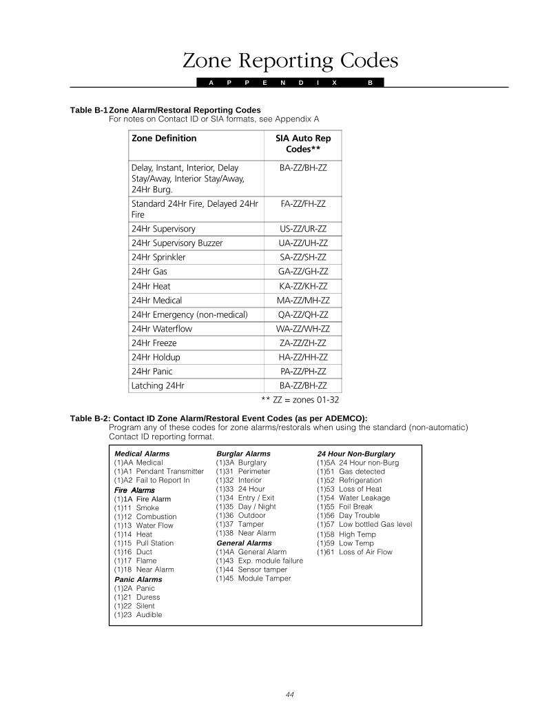
44
Zone Reporting CodesA P P E N D I X V B
Medical Alarms(1)AA Medical(1)A1 Pendant Transmitter(1)A2 Fail to Report InFire AlarmsFire AlarmsFire AlarmsFire AlarmsFire Alarms(1)1A Fire Alarm(1)11 Smoke(1)12 Combustion(1)13 Water Flow(1)14 Heat(1)15 Pull Station(1)16 Duct(1)17 Flame(1)18 Near AlarmPanic Alarms(1)2A Panic(1)21 Duress(1)22 Silent(1)23 Audible
Burglar Alarms(1)3A Burglary(1)31 Perimeter(1)32 Interior(1)33 24 Hour(1)34 Entry / Exit(1)35 Day / Night(1)36 Outdoor(1)37 Tamper(1)38 Near AlarmGeneral Alarms(1)4A General Alarm(1)43 Exp. module failure(1)44 Sensor tamper(1)45 Module Tamper
Table B-2: Contact ID Zone Alarm/Restoral Event Codes (as per ADEMCO):Program any of these codes for zone alarms/restorals when using the standard (non-automatic)Contact ID reporting format.
Zone Definition SIA Auto RepCodes**
Delay, Instant, Interior, DelayStay/Away, Interior Stay/Away,24Hr Burg.
BA-ZZ/BH-ZZ
Standard 24Hr Fire, Delayed 24HrFire
FA-ZZ/FH-ZZ
24Hr Supervisory US-ZZ/UR-ZZ
24Hr Supervisory Buzzer UA-ZZ/UH-ZZ
24Hr Sprinkler SA-ZZ/SH-ZZ
24Hr Gas GA-ZZ/GH-ZZ
24Hr Heat KA-ZZ/KH-ZZ
24Hr Medical MA-ZZ/MH-ZZ
24Hr Emergency (non-medical) QA-ZZ/QH-ZZ
24Hr Waterflow WA-ZZ/WH-ZZ
24Hr Freeze ZA-ZZ/ZH-ZZ
24Hr Holdup HA-ZZ/HH-ZZ
24Hr Panic PA-ZZ/PH-ZZ
Latching 24Hr BA-ZZ/BH-ZZ
** ZZ = zones 01-32
Table B-1Zone Alarm/Restoral Reporting CodesFor notes on Contact ID or SIA formats, see Appendix A
24 Hour Non-Burglary(1)5A 24 Hour non-Burg(1)51 Gas detected(1)52 Refrigeration(1)53 Loss of Heat(1)54 Water Leakage(1)55 Foil Break(1)56 Day Trouble(1)57 Low bottled Gas level(1)58 High Temp(1)59 Low Temp(1)61 Loss of Air Flow
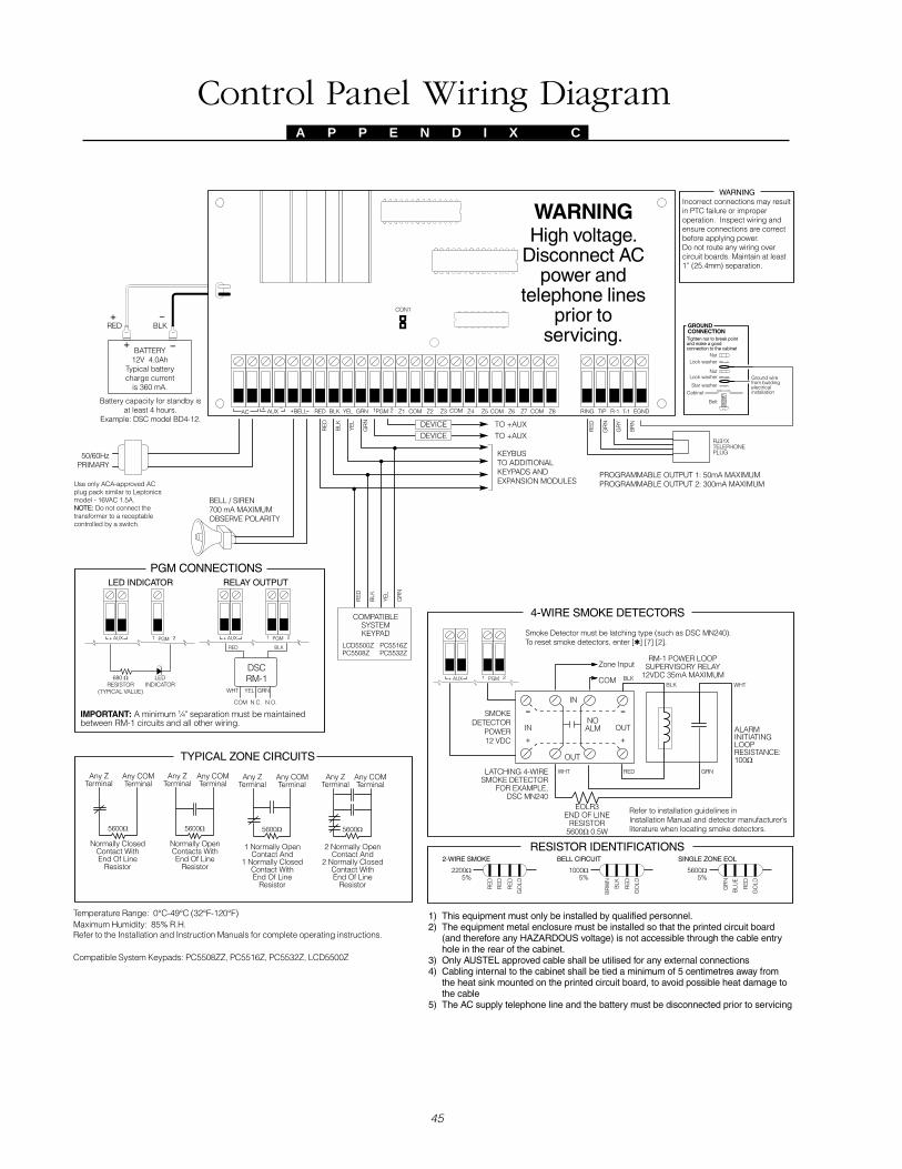
45
Control Panel Wiring DiagramA P P E N D I X V C

Modules Supported on the PC5015 v2.3AA P P E N D I X V D
eludoM eludoM eludoM eludoM eludoM detroppuS detroppuS detroppuS detroppuS detroppuS stnemmoC stnemmoC stnemmoC stnemmoC stnemmoC
0855trocsE seY
4025CP seY
8025CP seY
8015CP seY
L8015CP seY
X.1v2315CP seY sdapyeKdlehdnaHrostnadneP,syeKsseleriWroftroppusoN
X.2v2315CP seY troppussyeKsseleriWdeifitnedioN
X.3v2315CP seY
6055CP oN
8055CP seY troppusenozdapyeKoN
Z8055CP seY
6155CP seY troppusenozdapyeKoN
Z6155CP seY
2355CP seY troppusenozdapyeKoN
Z2355CP seY
X.1v0055DCL seY detroppustonsegassemyalpsidemoS;troppusenozdapyeKoN
X.2vZ0055DCL seY
8095CP oN
8295CP seY
1.2votX.1v0045CP seY detroppustonsegassemgnitnirpemoS
2.2v0045CP seY
0001skniL seY
0512skniL seY
0542skniL seY
1-MLD oN
X.1v4-MLD oN
L0.1v4-MLD seY
7-MLD oN

NOTES:

FCC COMPLIANCE STATEMENT
CAUTION: Changes or modifications not expressly approved by Digital Security Controls Ltd. could void your authority to use this equipment.
This equipment has been tested and found to comply with the limits for a Class B digital device, pursuant to Part 15 of the FCC Rules. These limits are designed to provide reasonableprotection against harmful interference in a residential installation. This equipment generates, uses and can radiate radio frequency energy and, if not installed and used in accordancewith the instructions, may cause harmful interference to radio communications. However, there is no guarantee that interference will not occur in a particular installation. If this equipmentdoes cause harmful interference to radio or television reception, which can be determined by turning the equipment off and on, the user is encouraged to try to correct the interferenceby one or more of the following measures:• Re-orient the receiving antenna.• Increase the separation between the equipment and receiver.• Connect the equipment into an outlet on a circuit different from that to which the receiver is connected.• Consult the dealer or an experienced radio/television technician for help.The user may find the following booklet prepared by the FCC useful: “How to Identify and Resolve Radio/Television Interference Problems”. This booklet is available from the U.S.Government Printing Office, Washington D.C. 20402, Stock # 004-000-00345-4.
IMPORTANT INFORMATION
This equipment complies with Part 68 of the FCC Rules. On the side of this equipment is a label that contains, among other information, the FCC registration number of this equipment.
NOTIFICATION TO TELEPHONE COMPANY The customer shall notify the telephone company of the particular line to which the connection will be made, and provide the FCCregistration number and the ringer equivalence of the protective circuit.
FCC Registration Number: F53CAN-32104-AL-EREN: 0.6BUSOC Jack: RJ31X
TELEPHONE CONNECTION REQUIREMENTS Except for the telephone company provided ringers, all connections to the telephone network shall be made through standardplugs and telephone company provided jacks, or equivalent, in such a manner as to allow for easy, immediate disconnection of the terminal equipment. Standard jacks shall be soarranged that, if the plug connected thereto is withdrawn, no interference to the operation of the equipment at the customer’s premises which remains connected to the telephone networkshall occur by reason of such withdrawal.INCIDENCE OF HARM Should terminal equipment or protective circuitry cause harm to the telephone network, the telephone company shall, where practicable, notify the customerthat temporary disconnection of service may be required; however, where prior notice is not practicable, the telephone company may temporarily discontinue service if such action is deemedreasonable in the circumstances. In the case of such temporary discontinuance, the telephone company shall promptly notify the customer and will be given the opportunity to correctthe situation.ADDITIONAL TELEPHONE COMPANY INFORMATION The security control panel must be properly connected to the telephone line with a USOC RJ-31X telephonejack.The FCC prohibits customer-provided terminal equipment be connected to party lines or to be used in conjunction with coin telephone service. Interconnect rules may vary from stateto state.CHANGES IN TELEPHONE COMPANY EQUIPMENT OR FACILITIES The telephone company may make changes in its communications facilities, equipment, operations orprocedures, where such actions are reasonably required and proper in its business. Should any such changes render the customer’s terminal equipment incompatible with the telephonecompany facilities the customer shall be given adequate notice to the effect modifications to maintain uninterrupted service.RINGER EQUIVALENCE NUMBER (REN) The REN is useful to determine the quantity of devices that you may connect to your telephone line and still have all of those devicesring when your telephone number is called. In most, but not all areas, the sum of the RENs of all devices connected to one line should not exceed five (5.0). To be certain of the numberof devices that you may connect to your line, you may want to contact your local telephone company.EQUIPMENT MAINTENANCE FACILITY If you experience trouble with this telephone equipment, please contact the facility indicated below for information on obtaining serviceor repairs. The telephone company may ask that you disconnect this equipment from the network until the problem has been corrected or until you are sure that the equipment is notmalfunctioning.Digital Security Controls Ltd. 160 Washburn St., Lockport, NY 14094

©2001 Digital Security Controls Ltd.
Toronto, Canada • www.dsc.com
Printed in Canada 29004894 R002