installation, maintenance and user instructions zip · pdf filezip inline electronic...
TRANSCRIPT
ZIP InLineElectronic Instantaneous
Water Heaters
Models: ES3, ES4 & ES6Issued February 2012
Installation, Maintenance and User Instructions
Please read these instructions carefully before commencing installation of the InLine water heater. Please leave these
instructions with the end user after installation.
Zip Heaters (UK) Ltd14 Bertie Ward WayDerehamNorfolkNR19 1TE
Telephone: 0845 6024533Fax: 01362 692448Web: www.zipheaters.co.uk
The terms ‘Zip’ and ‘InLine’ are registered trademarks
9120-1411
Front CoverBack Cover

Inside Back Cover Inside Front Cover

ES3, ES4 & ES6 Instructions. Issue: No. 2 Page 1 February / 2012
Contents
Contents 1
Description 2
Approvals 2
Safety information 3
Technical data 5
Parts list 6
Installation 7
Requirements 7
Installation site 7
Installing the appliance 8
Electrical connection / circuit diagram 11
Commissioning 12
Maintenance and cleaning 13
Fault finding 14
Warranty 16
Please read these instructions carefully before commencing installation of the InLine Electronic Instantaneous Water Heater.
Please leave these instructions with the end user after installation.
To ensure you have the latest revision of this instruction manual, please visit www.zipheaters.co.uk to download the latest copy.
In order to preserve our environment we ask that you dispose of this product correctly. Please contact Zip Customer Service for advice on 0845 602 4533.

ES3, ES4 & ES6 Instructions. Issue: No. 2 Page 2 February / 2012
DescriptionZip InLine ES3, ES4 and ES6 instantaneous water heaters are compact electronically controlled instantaneous water heaters for hand washing.This small instantaneous water heater is intended to provide economical heating of water for a wash basin when installed together with a sanitary water fitting. When the hot-water tap is opened, the heater switches itself on automatically when the minimum water flow rate is exceeded and heats the water as it passes through the appliance.The heater is pre-set in the factory to an outlet temperatu re of about 38°C, which is ideal for hand washing. When this temperature is reached, the electronic regulator reduces the power in order to ensure that the outlet temperature does not exceed this value. This automatic temperature regulation means that it is only necessary to open the hot water tap to obtain water at a constant, safe temperature for washing hands. If the set outlet temperature is not reached, slightly reduce the flow of water from the tap. Cold water may be added if a lower temperature is required.If the flow rate is too low or if the hot water tap is closed, the appliance switches itself off automatically. For an optimum flow of water, always fit the special jet regulator supplied with the appliance. This regulator should be inserted into the threaded retainer on the tap outlet.The maximum possible outlet temperature is determi ned by the temperature of the incoming water, the flow rate and the heating power of the heater. The temperature set point and flow rate can be preset inside the appli ance to achieve an outlet temperature between about 30°C and 50°C.Power consumption is also regulated based on outlet temperature to ensure the required temperature is achieved exactly to the degree and irrespective of fluctuations in voltage and water pressure.The maximum inlet temperature of 60°C is suitable for use with preheated water e.g. from solar heating systems.
ApprovalsZip InLine ES3, ES4 and ES6 are VDE approved to the LVD and EMC directives and CE endorsed.Zip InLine ES3, ES4 and ES6 have been examined, tested and found when correctly fitted to comply with the requirements of the United Kingdom Water Regulations / Byelaws (Scotland). The products are listed under the WRAS (Water Regulations Advisory Scheme) Water Fittings and Materials Directory.

ES3, ES4 & ES6 Instructions. Issue: No. 2 Page 3 February / 2012
Safety InformationWArnIng• Installation, commissioning and maintenance of this appliance must
only be carried out by a competent installer who will then be responsible for adhering to all relevant standards and regulations.
• The front cover of the appliance must never be opened before disconnecting the appliance from the mains power supply.
• The appliance must be permanently connected to the supply through an isolating switch with a contact separation of at least 3mm in all poles.
• To protect the appliance, a circuit breaker must be fitted with a rating suitable for the nomi nal current of the appliance.
• The cross sectional area of the connection cable must be appropriate for the power rating and location of the appliance. See Technical Data.
• The connecting cable must be adequately secured.• This appliance must be earthed at all times.• Check that the power supply is switched off prior to electrical connection.• The appliance, its wiring and piping must not be modified in any way.• In case of malfunction isolate the power supply immediately. In case of leaks
also isolate the water supply. Repairs must only be carried out by Zip Heaters (UK) Ltd or an authorised Zip service engineer.
• Temperatures in excess of approximately 43°C are perceived as hot, especially by children, and may cause a feeling of burning.
• This appliance must not be used by any person (inclu ding children) with limited physical, sensorial or mental abilities or failing experience and/or knowledge unless they are supervised by a person responsible for their safety or received instructions about how to use the appliance.
• Children should be supervised in order to make sure that they do not play with the appliance.
WArnIng:Indicates a potentially hazardous situation, which, if not avoided, could result in death and/or serious injury and/or property damage.
CAUTIOn: Indicates a potentially hazardous situation, which, if not avoided, may result in property damage.
IMPOrTAnT:
PLEASE rEAD THESE InSTrUCTIOnS CArEFULLY. nOTE THE SAFE OPErATIOnAL rEQUIrEMEnTS, WArnIngS AnD CAUTIOnS. USE THIS PrODUCT COrrECTLY AnD WITH CArE FOr THE PUrPOSE FOr WHICH IT IS InTEnDED. FAILUrE TO DO SO MAY CAUSE DAMAgE AnD/Or PErSOnAL InJUrY, AnD WILL InVALIDATE THE WArrAnTY. rETAIn THESE InSTrUCTIOnS FOr FUTUrE USE.

ES3, ES4 & ES6 Instructions. Issue: No. 2 Page 4 February / 2012
CAUTIOn • Optimum operation is ensured at a water flow pressure of 0.2 to 0.4 MPa
(2-4 bar). The appliance must not be subjected to pressure exceeding 1.0 MPa (10 bar).
• The appliance must only be used when correctly installed and in perfect working order.
• The appliance must be installed in a frost-free room and must never be exposed to frost.
• The ES range is not recommended for use with thermostatic mixing valves or taps.
• The appliance must be completely filled with water before being switched on. • Before commissioning for the first time and each time the appliance is emptied
(e.g. due to work on the plumbing system or maintenance), the appliance must be vented by opening and closing the hot water tap until all air has been eliminated from the water heater and no more air emerges before re-connecting to the electrical supply.
• The appliance must only be used for heating potable water. The specific water resistance must not fall below the required value indicated on the rating plate. The appliance must not be used for any other purpose.
• Incoming water temperature must not exceed 60°C. • When the appliance has been in use for some time, the fittings may be very
hot.• If inlet temperature is up to 60°C (eg. fed from a solar supply) mixing with cold
water will be required to ensure a safe temperature at the outlet.• The Zip InLine is intended for connection to mains supply only. In any other
case please contact Zip on 0845 602 4533 for advice. • Zip Heaters (UK) Ltd cannot be held liable for any damages caused by
failure to observe these instructions.
ES3, ES4 & ES6 Instructions. Issue: No. 2 Page 5 February / 2012
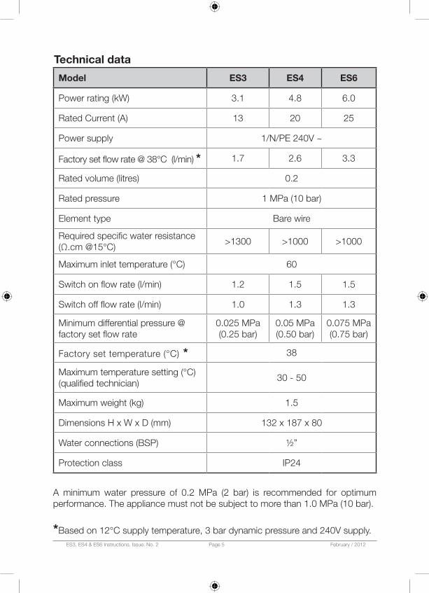
Technical data
Model ES3 ES4 ES6
Power rating (kW) 3.1 4.8 6.0
Rated Current (A) 13 20 25
Power supply 1/N/PE 240V ~
Factory set flow rate @ 38°C (l/min) * 1.7 2.6 3.3
Rated volume (litres) 0.2
Rated pressure 1 MPa (10 bar)
Element type Bare wire
Required specific water resistance (Ω.cm @15°C)
>1300 >1000 >1000
Maximum inlet temperature (°C) 60
Switch on flow rate (l/min) 1.2 1.5 1.5
Switch off flow rate (l/min) 1.0 1.3 1.3
Minimum differential pressure @ factory set flow rate
0.025 MPa (0.25 bar)
0.05 MPa (0.50 bar)
0.075 MPa (0.75 bar)
Factory set temperature (°C) * 38
Maximum temperature setting (°C) (qualified technician)
30 - 50
Maximum weight (kg) 1.5
Dimensions H x W x D (mm) 132 x 187 x 80
Water connections (BSP) ½”
Protection class IP24
A minimum water pressure of 0.2 MPa (2 bar) is recommended for optimum performance. The appliance must not be subject to more than 1.0 MPa (10 bar).
*Based on 12°C supply temperature, 3 bar dynamic pressure and 240V supply.

ES3, ES4 & ES6 Instructions. Issue: No. 2 Page 6 February / 2012
Item Part no. Description
1
IN80324 Heating Spiral for ES3
IN80326 Heating Spiral for ES4
IN80327 Heating Spirals for ES6 (Pair)
2 IN95622 Front Cover
3IN80352 Complete fixing kit (wall bracket with screws & fixing plugs)
IN80689 Wall bracket only
4 IN80353 Set of small spare parts (seals, nozzle for cable entry, etc.)
5 IN80080 Filter sieve (fine filter)
6 IN80750Water connection set, including two water connections and seals
7IN80372 Flow adjustment screw with seal for ES3 and ES4
IN803721 Flow adjustment screw with seal for ES6
8 IN86072 Temperature sensor
9 IN80427 Safety thermal cut-out and seals
ZL009 Jet regulator for ES3 and ES4 (Not shown)
ZL010 Jet regulator for ES6 (Not shown)
1
2
3
4
5 67 8
9
Parts list
ES3, ES4 & ES6 Instructions. Issue: No. 2 Page 7 February / 2012
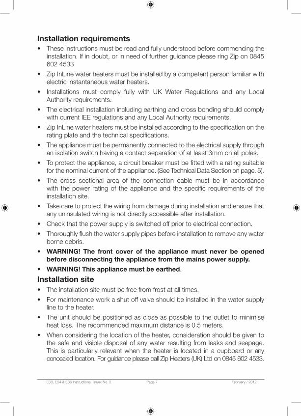
Installation requirements• These instructions must be read and fully understood before commencing the
installation. If in doubt, or in need of further guidance please ring Zip on 0845 602 4533
• Zip InLine water heaters must be installed by a competent person familiar with electric instantaneous water heaters.
• Installations must comply fully with UK Water Regulations and any Local Authority requirements.
• The electrical installation including earthing and cross bonding should comply with current IEE regulations and any Local Authority requirements.
• Zip InLine water heaters must be installed according to the specification on the rating plate and the technical specifications.
• The appliance must be permanently connected to the electrical supply through an isolation switch having a contact separation of at least 3mm on all poles.
• To protect the appliance, a circuit breaker must be fitted with a rating suitable for the nominal current of the appliance. (See Technical Data Section on page. 5).
• The cross sectional area of the connection cable must be in accordance with the power rating of the appliance and the specific requirements of the installation site.
• Take care to protect the wiring from damage during installation and ensure that any uninsulated wiring is not directly accessible after installation.
• Check that the power supply is switched off prior to electrical connection.
• Thoroughly flush the water supply pipes before installation to remove any water borne debris.
• WArnIng! The front cover of the appliance must never be opened before disconnecting the appliance from the mains power supply.
• WArnIng! This appliance must be earthed.
Installation site• The installation site must be free from frost at all times.
• For maintenance work a shut off valve should be installed in the water supply line to the heater.
• The unit should be positioned as close as possible to the outlet to minimise heat loss. The recommended maximum distance is 0.5 meters.
• When considering the location of the heater, consideration should be given to the safe and visible disposal of any water resulting from leaks and seepage. This is particularly relevant when the heater is located in a cupboard or any concealed location. For guidance please call Zip Heaters (UK) Ltd on 0845 602 4533.

ES3, ES4 & ES6 Instructions. Issue: No. 2 Page 8 February / 2012
Fig. 2
• Hot and cold water connecting pipes should be WRAS approved and of copper or steel construction. Plastic pipes may only be used if conforming to DIN 16893 Series 2.
• The specific resistance of the supply water must be >1300 Ωcm at 15°C for ES3 and >1000 Ωcm at 15°C for ES4 and ES6. The specific resistance can be checked with the local water supply company.
• Thoroughly flush the water supply pipes before installation to remove any water borne debris.
Installing the appliance1. Secure the wall bracket to the wall with screws and wall plugs supplied (Fig. 1).
2. Place the appliance on the wall bracket and snap into position (Fig. 2).
Note! This appliance is intended for under sink installation with the water connections pointing vertically upwards.
Fig. 1
Drill size Ø 7mm.
Use the mounting bracket as a guide for fixing marks.
Drilling width variable: 105mm minimum to 145mm maximum.
ES3, ES4 & ES6 Instructions. Issue: No. 2 Page 9 February / 2012
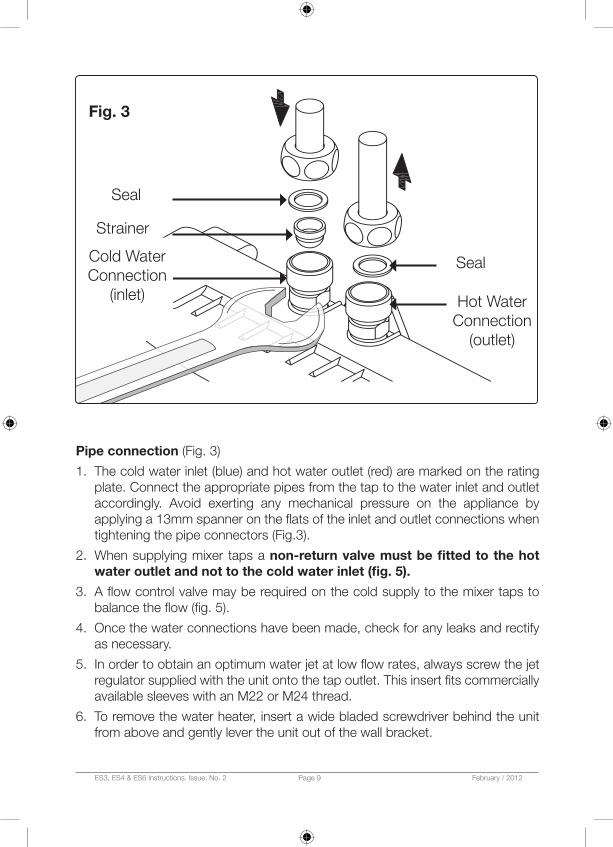
Seal
Seal
Hot Water Connection
(outlet)
Strainer
Cold Water Connection
(inlet)
Fig. 3
Pipe connection (Fig. 3)
1. The cold water inlet (blue) and hot water outlet (red) are marked on the rating plate. Connect the appropriate pipes from the tap to the water inlet and outlet accordingly. Avoid exerting any mechanical pressure on the appliance by applying a 13mm spanner on the flats of the inlet and outlet connections when tightening the pipe connectors (Fig.3).
2. When supplying mixer taps a non-return valve must be fitted to the hot water outlet and not to the cold water inlet (fig. 5).
3. A flow control valve may be required on the cold supply to the mixer taps to balance the flow (fig. 5).
4. Once the water connections have been made, check for any leaks and rectify as necessary.
5. In order to obtain an optimum water jet at low flow rates, always screw the jet regulator supplied with the unit onto the tap outlet. This insert fits commercially available sleeves with an M22 or M24 thread.
6. To remove the water heater, insert a wide bladed screwdriver behind the unit from above and gently lever the unit out of the wall bracket.

ES3, ES4 & ES6 Instructions. Issue: No. 2 Page 10 February / 2012
Typical installationFig. 4 / 5 show unvented installation with closed outlet tap.Fig. 4a shows open vented installation
Fig. 4
You may also use an open vented installation.
187mm
132mm
Fig. 5
Service Valve
Flow Control Valve
Mains Supply
Insert Jet regulator
Jet regulator
rear Cable Entry
non-return valve
Fig. 4a

ES3, ES4 & ES6 Instructions. Issue: No. 2 Page 11 February / 2012
Electrical connectionDo not switch on the electric power at this time.WArnIng! To prevent damage to the appliance, the instantaneous water heater must be purged of air before using it for the first time.
PUrgIngBefore connecting the electrical supply, open and close the hot water tap until the water runs smoothly and no more air emerges.nOTE! Every time the appliance is drained (e.g. after work on the plumbing system, if there is a risk of frost or following repair work), the heater must be purged in this way before reconnecting the power supply.
WARNING! This appliance must be earthed. Installation must be carried out by a competent electrician.The electrical installation including earthing and cross bonding should comply with current IEE regulations and any Local Authority requirements.IMPOrTAnT: The appliance must be installed according to the specification on the rating plate and the technical specifications. Ensure that the voltage marked on the appliance matches the power supply.The appliance must be permanently connected to the electrical supply through an isolation switch having a contact separation of at least 3mm on all poles. To protect the appliance, a circuit breaker must be fitted with a rating suitable for the nomi nal current of the appliance. The cross sectional area of the connection cable must be in accordance with the power rating of the appliance and the specific requirements of the installation site.Take care to protect the wiring from damage during installation and ensure that any uninsulated wiring is not directly accessible after installation.The cable must be adequately secured.WARNING! Check that the power supply is switched off prior to electrical connection!
Fig. 6
321
Circuit Diagram
1. Electronic regulator
2. Safety thermal cut-out
3. Heating elementPE
N
L

ES3, ES4 & ES6 Instructions. Issue: No. 2 Page 12 February / 2012
Commissioning1. Close the circuit breaker to connect the electrical supply.2. Check everything is working as it should and the water temperature is achieving
the desired temperature. If not follow the guide below to correct the temperature.
Temperature & flow adjustment
(Authorised Technicians Only)The maximum outlet temperature can be set between 30°C and 50°C. The factory setting is 38°C.Water too hot• Decrease the temperature by turning the potentiometer (Fig. 7) clockwise until
the desired temperature is achieved.Water too cold• Increase the temperature by turning the potentiometer counter clockwise until
the desired temperature is achieved.• If the desired temperature cannot be achieved the red LED on the PCB will light
(solid) to show that the unit cannot achieve the preset temperature. (See LED functions on page 14).
• In this case it will be necessary to adjust the water flow through the unit.• The flow rate can be adjusted with the adjustment screw (Fig. 8)• Turning this screw clockwise reduces the flow rate; turning it counter-clockwise
increases the flow rate.• Turn the adjustment screw clockwise; reducing the flow rate until the desired
temperature is achieved.
Fig. 7 Fig. 8
CAUTIOn! Do not turn the adjustment screw further than the indent mark in order to avoid water leakage.

ES3, ES4 & ES6 Instructions. Issue: No. 2 Page 13 February / 2012
nOTE! When used to supply a mixer tap a flow restrictor may be required on the cold supply to the tap to balance the flows.For further information see the Fault Finding table, page 14.When the unit has been commissioned, explain the functions of the heater to the end user and ensure they know how to use the appliance.Hand over these instructions for the user to keep.
Maintenance and cleaningnOTE! Maintenance work must only be carried out by a competent person familiar with instantaneous water heaters.Plastic surfaces and sanitary fittings should only be wiped with a damp cloth. Never use abrasive cleaning agents or solvents.Outlet fittings (jet regulator Fig. 5) should be unscrewed from the tap nozzle and cleaned at regular intervals. • Rinse the regulator with water and brush off the debris. For difficult to remove
deposits, soak in white vinegar (or a proprietary scale cleaner) for a few minutes and scrub with a toothbrush.
• If any parts are cracked or broken, replace them. If the washer has hardened, it should be replaced.
• With the debris cleaned out, screw the regulator back into the tap. Hand tightening should be adequate.
The electrical and plumbing components should be inspected regularly by a competent person to ensure proper functioning and operational safety. Water quality should be considered when determining the frequency of inspection. Each time the appliance is emptied (e.g. due to work on the plumbing system, if there is a risk of freezing or in case of maintenance), the appliance must be purged by opening and closing the hot water tap until all air has been eliminated from the water heater and no more air emerges before re-connecting to the electrical supply.

ES3, ES4 & ES6 Instructions. Issue: No. 2 Page 14 February / 2012
Fault fi ndingRepairs should only be carried out by competent persons familiar with electric instantaneous water heaters. All service work should be performed by an authorized Zip service engineer – for details of the full range of services available call Zip Service on: 0845 602 4533.When calling for service, please always specify the appliance model and serial number.The following table will be helpful in determining the causes of some common problems and their solutions
Problem Possible cause Solution
No water fl ows Water supply is turned offOpen the main water valve / shut off valve
Water fl ows more slowly than expected
The Jet Regulator is not fi tted
Fit the correct Jet Regulator (see Fig. 5)
Water pressure is not suffi cient
Check the water fl ow pressure, check the water fl ow adjustment. See fi g. 8
Dirt in the pipesRemove any dirt from the fi lter, valves and / or taps, check the technical data
The heater switches itself on and off
Water pressure is varying, fl ow rate is too low
Remove any dirt,increase the fl ow water pressure, close other taps, open the shut off valve further
LED Functions
green LED fl ashing Standby mode
green LED constantly on Appliance is heating water
red LED constantly onThe required outlet temperature cannot be achieved at maximum power
red LED fl ash code:
Long- short-short-short-long Inlet temperature too high
Long-short-short-short-short Temperature sensor faulty

ES3, ES4 & ES6 Instructions. Issue: No. 2 Page 15 February / 2012
Problem Possible cause Solution
Water remains cold although the appliance switches on
Faulty heating elementReplace heating element (by authorised technician only)
Appliance does not switch on and the water remains cold
Water pressure is not sufficient
Adjust the water flow see fig. 8. Open the shut-off valve.Fit the correct jet regulator (see Fig. 5)
Dirt in the inlet or outlet.Remove dirt from the inlet and outlet
Electric supply incorrect Check the electric supply
Circuit breaker has tripped. Safety thermal cut-out has tripped
Have the fault rectified by a technician and reset the circuit breaker / thermal cut-out
Hot water temperature varies
Supply voltage varies.Water connections reversed
Check the supply voltage.Check installation
Hot water temperature flow too low
Rate is too high. Inlet temperature is too low
Adjust the flow either at the tap, the valve or the flow adjustment screw
Power supply is too low
Preset the temperature, measure the temperatures and flow rate and compare with the technical data, check the power supply
Faulty heating elementReplace the heating element by an authorised technician

ES3, ES4 & ES6 Instructions. Issue: No. 2 Page 16 February / 2012
The Zip appliance you have chosen is precision-built from the finest materials available and should give many years of trouble free service.
Certain warranties may be implied by law into your contract with Zip. The warranty provided below is additional to these implied warranties and nothing set out below shall limit your statutory rights or rights at law.Zip Heaters (UK) Ltd warrants that, should any part fail within 12 calendar months of installation, that part will be repaired or replaced free of charge by Zip or its Distributor or Service Provider, except as set out below, provided the appliance is installed and used strictly in accordance with the instructions supplied, and that failure is not due to accident, misuse, abuse, unsuitable water conditions, or to any alteration, modification or repair by any party not expressly nominated by Zip.No costs are payable by the customer other than any mileage or travelling-time charges incurred by a Zip Service Provider or the cost of removal, cartage and re-installation of any component of the appliance if it needs to be returned for repair to Zip or its Distributor.This warranty does not cover damage resulting from non-operation of the appliance or consequential damage to any other goods, furnishings or property.Zip does not exclude, restrict or modify any liability that cannot be excluded, restricted or modified or which cannot, except to a limited extent, be excluded, restricted or modified as between the owner or user and Zip under the laws applicable.Furthermore, this warranty does not displace any statutory warranty, but, to the extent to which Zip is entitled to do so, the liability of Zip under any statutory warranty will be limited at Zip’s option to the replacement of the appliance or supply of equivalent appliance, the payment of the cost of replacing the appliance or acquiring an equivalent appliance, or the payment of the cost of having the appliance repaired or the repair of the appliance.
Warranty
nOTE: It is our policy to continually improve products and as such we reserve the right to alter data, specifications and component parts without prior notice.To ensure you have the latest revision of this instruction manual, please visit www.zipheaters.co.uk to download the latest copy.IMPOrTAnT: No liability is accepted for incorrect use of this product.