installation instructions - wolf...
TRANSCRIPT

Installation instructionsGas fired condensing boilersCGB-11 BoilerCGB-20 BoilerCGB-K-20 Combi boilerCGB-24 BoilerCGB-K-24 Combi boiler
Art.-Nr. 3061344_201509 Subject to technical modifications GB
Wolf GmbH · Postfach 1380 · 84048 Mainburg · Tel. 08751/74-0 · Fax 08751/741600 · Internet: www.wolf-heiztechnik.de

2 3061344_201509
IndexSafety instructions ........................................................................................................3
Standards and regulations........................................................................................ 4-5
Control unit / Function / Operation............................................................................ 6-7
Dimensions / Transport dimensions ......................................................................... 8-9
Layout ....................................................................................................................10-11
Positioning ..................................................................................................................12
Assembly ....................................................................................................................13
Installation ............................................................................................................ 14-17
Installation of a balanced flue system ......................................................18
Power supply ..................................................................................... 19-22
Filling the system .....................................................................................23
Commissioning .................................................................................. 24-25
Checking the gas supply pressure...........................................................26
Filling the siphon / Checking the gas supply pressure.............................27
Displaying / modifying control parameters ...............................................28
Limiting the maximum output ...................................................................29
Selecting the pump stage ........................................................................30
Testing the combustion parameters .........................................................31
CO2 settings ...................................................................................... 32-33
Commissioning report ..............................................................................34
Technical conversion options for gas fired condensing boiler CGB............................35
Conversion of combi boilers to boilers with cylinder ...................................................36
Maintenance ......................................................................................................... 37-51
Modulating pump (class A) .........................................................................................52
3-stage-pump .............................................................................................................53
Design information................................................................................................ 54-67
Underfloor heating system..........................................................................................68
Technical maintenance and engineering details .........................................................69
Wiring diagram ...........................................................................................................70
Specification ...............................................................................................................71
Troubleshooting ..........................................................................................................72
Product fiche according to Regulation (EU) no. 811/2013 ..........................................73
Technical parameters according to EU regulation no. 813/2013 ................................75
EC-Declaration of Conformity to Type ........................................................................76

33061344_201509
The following symbols are used in conjunction with these important instructions concerning personal safety as well as technical reliability.
Safety instructions
This indicates technical instructions which you must observe to prevent material losses and boiler malfunctions.
NB
Danger through ‚live‘ electrical components.Please note: Switch OFF the ON/OFF switch before removing the casing.
Never touch electrical components or contacts when the ON/OFF switch is in the ON position. This brings a risk of electrocution, which may result in injury or death.
The main supply terminals are ‚live‘ even when the ON/OFF switch is in the OFF position.
„Safety instructions“ are instructions with which you must comply exactly, to prevent injury and material losses.
Fig.: Gas connection: Escaping gas may cause poisoning or the risk of explosion
Fig.: Terminal box: Danger from electric power
Fig.: Ignition transformer, high voltage ignition electrode, combustion chamberRisk through ‚live‘ electrical components, risk of burning through hot components
Fig.: Gas combination valveDanger from electric powerEscaping gas may cause poisoning or the risk of explosion

4 3061344_201509
Standards and regulations
Note: Please read these instructions carefully before the installation and keep them in a safe place. Please also note the technical information in the appendix.
Requirements
The installation of the boiler must be in accordance with the relevant requirements of Gas Safety (Installation and Use) Regulations 1998, Health and Safety Document No. 635 (The Electricity at Work Regulations 1989), BS 7671 (IEE Wiring Regulations) and the Water Supply (Water Fitting) Regula-tions 1999, or The Water Bylaws 2000 (Scotland). It should also be in accordance with the relevant requirements of the Local Authority, Building Regulations, including amendments to the Approved Documents Part L and J 2002, The Building Regulations (Scotland), The Building Regulations (Northern Ireland) and the relevant recommendations of the following British Standards:
BS 5440: Flues and ventilation of gas fired boilers not ex-ceeding 70 kW net:
- Part 1: Flues - Part 2: VentilationBS 5449: Specification for forced circulation hot water for
domestic premises. BS 5546: Specification for gas hot water supplies for do-
mestic premises.BS 6700: Services supplying water for domestic use within
buildings and their curtilages. BS 6798: Specification for installation of gas fired boilers
not exceeding 60 kW input.BS 6891: Specification for installation of low pressure gas
pipework up to 28 mm (R1“) in domestic premises (2nd family gas).
BS 7593: Treatment of water in domestic hot water central heating systems.
Institute of Gas Engineers Publication IGE/UP/7/1998:„Guide for gas installations in timber framed housing“
Important: The appliance must be installed and serviced by a competent person as stated in the Gas Safety (Installation and Use) Regulations 1998. In IE, the installation must be in accordance with the current edition of I.S,813 ´Domestic Gas Installations´, the current Building Regulations and reference should be made to the current ECI rules for electrical instal-lation.
When tightening or loosening threaded connections always use suitable open-ended spanners (not pipe wrench, or extensions, etc.). Incorrect use and/or unsuitable tools can lead to damage (e.g. gas or water leaks)!
Any damage or loss resulting from technical modi-fications to the control unit or to the control compo-nents are excluded from our liability.Incorrect use can lead to a risk to life and limb or to a risk of material losses.
Obtain the permission of your mains gas supplier and flue gas inspector prior to the installation of Wolf gas fired boilers [where appropriate].
Wolf gas fired boilers must only be installed by a recognis-ed heating contractor. This heating contractor will also be responsible for the proper installation and commissioning of the heating system.
The following regulations, rules and guidelines must be ob-served during installation:- VDE 0722 / EN50165 Electrical equipment of heat gene-
rators with non-electrical heating systems.
- DIN EN 12828 Heating systems in buildings, desi-gning hot water heating systems
- EN 60335-1 Safety of electrical equipment for domestic use and similar purposes
- VDE 0470 / EN 60529 Protection through housings

53061344_201509
Gas fired condensing boiler CGB-...
Gas fired condensing boilers according to DIN EN 297 / DIN 3368 T5,T6,T7,T8 / DIN EN 437 / DIN EN 483 (draft)/ DIN EN 677 (draft) / DIN EN 625 and Gas Appliance Directive 90/396/EEC (Gas Consumer Equipment), 92/42/EEC (Boiler Efficiency Directive), 2006/95/EG (Low Voltage Directive), and 89/336/EEC (EMC Directive), with electronic ignition and electronic flue gas temperature monitoring, for low temperature heating and DHW production in heating systems with flow temperatures up to 95 °C and 3 bar design pressure according to DIN EN 12828 part 3.The Wolf gas fired boiler is also approved for installation in garages.
Standards and regulations
Open flue gas fired condensing boilers must only be installed in a room which complies with the appropriate ventilation requirements. Other-wise there is a risk of asphyxiation and poiso-ning. Read these installation and maintenance instructions before installing the boiler. Also take the Technical Guide into consideration.Poorly vented LPG tanks can lead to ignition problems. In such cases, contact your local LPG supplier.
Fig.: Wolf gas fired condensing boiler
To save energy and protect against scaling if the total hardness is greater than 2.5 mol/m³, the DHW temperature may be set to a maximum of 50 °C.
If the total hardness is greater than 3.58 mol/m³, we recommend using a water treatment facility in the cold water supply line for DHW heating, to prolong the maintenance interval (descaling DHW heat exchanger).

6 3061344_201509
Control unit / Function / Operation
DHW temperature selectorWhen gas fired condensing boilers are combined with a DHW cylinder, setting 1 - 9 corresponds to a cylinder temperature of 15 - 65 °C. The setting on the DHW thermo-stat becomes ineffective when the system is used in conjunction with a digital room thermostat or a weather-compensated controller. The temperature will then be selected at the controller (accessories). With combi boilers, setting 1 - 9 corresponds to a DHW temperature of 40 - 60 °C.
Heating water temperature selectorThe factory setting range 2 - 8 corresponds to a heating water temperature of 20 - 75 °C. The setting on the heating water thermostat becomes ineffective when the system is used in conjunction with a digital room thermostat or a weather-compensated controller.
ON/OFF switchThe gas fired boiler is OFF in position 0.
Reset A fault is reset by pressing the reset button which will also restart the system. Pressing the reset button reactivates the system, if there was no fault.
Illuminated ring as status indicator
0I
91
2 8
3 7
4 65
2 8
3 7
4 65
Display Explanation
Flashing green Standby (power supply ON, no heat demand)
Constant green Heat demand: pump running, burner OFF
Flashing yellow Emissions test mode
Constant yellow Burner ON, flame steady
Flashing red Fault
ON/OFF switch DHW temperatu-re selector
Pressure gauge
Reset button
Heating water tem-perature selector
Illuminated ring
Thermometer
73061344_201509
Control unit / Function / Operation
Note: The number of times the gas boiler can be started in heating mode is limited electro-nically. This limit can be bypassed by pressing the reset button. Then, the equipment starts immediately, as soon as a heating demand is present.
In summer mode, the circulation pump operates for approx. 30 seconds after a maximum idle period of 24 hours.
Anti-seizingpump protection
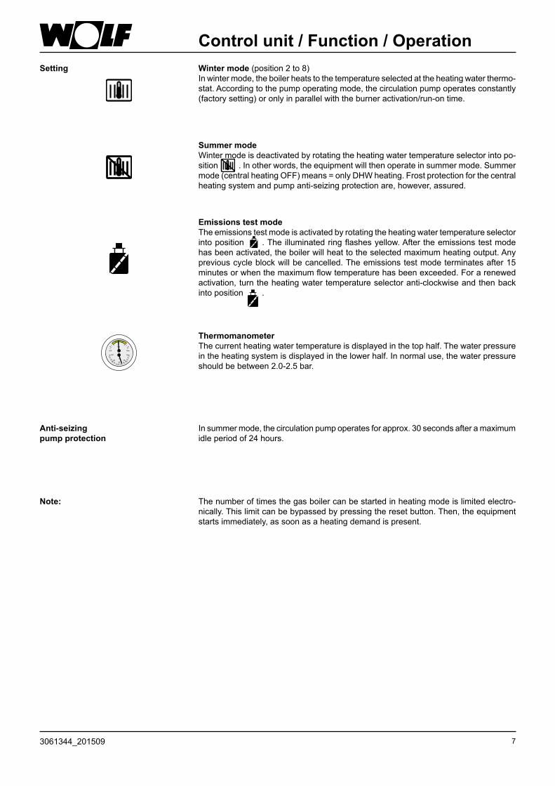
ThermomanometerThe current heating water temperature is displayed in the top half. The water pressure in the heating system is displayed in the lower half. In normal use, the water pressure should be between 2.0-2.5 bar.
Setting Winter mode (position 2 to 8)In winter mode, the boiler heats to the temperature selected at the heating water thermo-stat. According to the pump operating mode, the circulation pump operates constantly (factory setting) or only in parallel with the burner activation/run-on time.
Summer modeWinter mode is deactivated by rotating the heating water temperature selector into po-sition . In other words, the equipment will then operate in summer mode. Summer mode (central heating OFF) means = only DHW heating. Frost protection for the central heating system and pump anti-seizing protection are, however, assured.
Emissions test modeThe emissions test mode is activated by rotating the heating water temperature selector into position . The illuminated ring flashes yellow. After the emissions test mode has been activated, the boiler will heat to the selected maximum heating output. Any previous cycle block will be cancelled. The emissions test mode terminates after 15 minutes or when the maximum flow temperature has been exceeded. For a renewed activation, turn the heating water temperature selector anti-clockwise and then back into position .
°C
bar
2
1 3
120 0
40
60
3090

8 3061344_201509
Dimensions / Transport dimensionsCGB
CGB combined with CSW-120
Fig.: DimensionsFig.: Dimensions
Fig.: Dimensions
200
440
154 144
640
281
32
344
654
40
54
Fig.: Connections
1 2 6 3 4 5
DHW flow Heating flow Heating return Heating return DHW return Condensate drain
190
855
48
393
270-420
790
440
344
810
1800-1950

93061344_201509
CGB-K
Dimensions / Transport dimensions
Fig.: DimensionsFig.: Connections
Heating flow DHW connection (on site) DHW connection Gas connection Cold water inlet Cold water inlet (on site) Heating return Condensate drain
Fig.: Dimensions
70
54
640
654
40
32
281
120
200
440
344
Fig.: Dimensions
190
855
48
393
200
120
10
73
165
35
16
2m
in.4
00
75
82
81
22
14
1 2 3 4 5 6 78

10 3061344_201509
LayoutCGB
Manual air-vent valve
Flue pipe
Limit thermostat
Burner
Heating water heat exch.
Return sensor
Three-way diverter valve
Heating return
DHW flow
Gas supply pipe
Fan motor
Gas fan
Expansion vessel
Gas:air mixing chamber
Inlet pipe
Gas combination valve
Heating circuit pump(auto venting)
Overflow valve
Heating flow
DHW return
TBV/flow sensor
Flue gas temperature limiter
Gas restrictor
Condensate siphon
Limit thermostat(only for CGB-24)

113061344_201509
CGB-K
Manual air-vent valve
Flue pipe
Burner
Heating water heat exch.
Return sensor
Three-way diverter valve
DHW heat exchanger
Heating return
DHW connection
Gas supply pipe
Fan motor
Gas fan
Expansion vessel
Gas restrictor
Inlet pipe
Gas combination valve
Heating circuit pump(auto venting)
Overflow valve
Flow sensor
Cold water strainer with flow switch
Heating flow
Cold water inlet
Condensate siphon
Flue gas temperature limiter
Gas:air mixing chamberLimit thermostat
TBV/flow sensor
Limit thermostat(only for CGB-K-24)
Layout

12 3061344_201509
Positioning
The CG... gas condensing centre for mounting on the wall is delivered fully assembled with a power cable for the socket.
A clearance of 40 mm to the side and 400 mm to the ceiling is recommended to enable inspection and maintenance work to be carried out on the appliance, otherwise adequate inspection and function tests on components cannot be ensured during maintenance. The drain hoses must be secured with the fixing plate above the drain outlet (siphon). The drain should be able to be inspected
The gas fired boiler may only be installed in rooms which are protected from frost.
Furthermore, all gas boiler components must be freely acces-sible from the front, and flue gas measurements must be able to be taken. If minimum dimensions and accessibility are not maintained/given, Wolf may require accessibility to be provided during a service visit.
General notes
The combustion air supplied to the boiler must be free from chemicals, e.g. fluoride, chlorine or sulphur. Such materials are contained in sprays, solvents and cleaning agents. Under the most un-favourable conditions, these may lead to corrosion, even in the flue gas system.
During the boiler installation, ensure that no contaminants (e.g. drilling swarf) enter the gas fired boiler, otherwise faults may result. Use the enclosed polystyrene cover.
NB
Clearance between the boiler and combustible materials or components is not required, as temperatures are limited to 85 °C at the rated boiler output. However, explosive and easily combustible materials must not be used in the boiler room; these would create a risk of fire or explosion.
min
.
500
mm
min.
400 mm
First determine where the appliance is to be installed.Consider the flue gas outlet, the lateral clearances towards walls and ceilings, and any existing connections for gas, central heating, DHW and electrics.
The installation room and the combustion air supplied to the appliance must be free from chemicals, e.g. fluoride and chlorine or sulphur. Such materials are contained in sprays, paints, adhesives, solvents and cleaning agents. These may cause corrosion, even in the flue system.

133061344_201509
Assembly
- Mark the holes to be drilled ∅12 for the mounting bracket bearing minimum clearances in mind.
- Insert the rawl plugs and secure the mounting bracket with the screws provided.
- Hang the boiler with the mounting brace into the mounting bracket.
Mounting brace
Fig.: Mounting brace on the boiler
An installation template is provided with the boiler to mark out the fixing holes and connections.Align the template vertically and mark out the fixing holes. Maintain the minimum clearances towards walls and ceilings required for maintenance.
Fig.: Fixing holes for mounting bracket
min
. 562
mm
Ceiling
Initially, determine the location for the installation of the gas fired boiler.In your deliberations, consider the flue gas outlet, the lateral clearances towards walls and ceilings and any existing con-nections for gas, central heating, DHW and electrics.
Mounting the boiler with a mounting bracket
During the boiler installation ensure that the fixing components are sufficiently strong to carry its weight. Also consider the wall consistency, otherwise gas or water may escape which would result in a risk of explosions and flooding.
Opening the casing lid
We recommend you remove the casing lid during installation. Pivot the control unit lid down. Unlock the casing lid with the l.h. and r.h. rotating bolts.
Release the lower part of the casing lid and unhook at the top.
Fig.: Installation template
Fixing holes for mounting bracket ∅12
...GU-...
...GG-...
...GB/...CG-...
Fig.: Open the rotating locks
rotating lock

14 3061344_201509
Installation
You may determine the connections for cold water and DHW, for the central heating and gas supply pipe and safety valve drain using the subsurface installation template, if these ser-vices are laid under the surface.
Route the supply lines for gas, central heating and DHW underneath the surface in accordance with the enclosed installation template.
Supply line – subsurface version
You may determine the connections for cold water and DHW, for the central heating and gas supply pipe(s) and safety valve drain using the panel for unfinished walls (accessories), if these services are laid under the surface.Solder the elbows of the panel for unfinished walls to the supply lines. (Each of the elbows can be turned 360° for easy connection of the supply lines from any direction).
Fit the installation accessories.
Fig.: Panel for mounting on unfinished walls (accessories) for: CGB-K, CGB with FSW-120
Fig.: Subsurface installation template
Fig.: Panel for mounting on unfinished walls (accessories)
Fig.: Connection panel for surface mounted version (acces-sories) for: Gas fired boilers CGB
Fig.: Connection panel for surface mounted version (acces-sories) for: Gas fired combi boilers CGB-K
You may determine the connections for cold water and DHW, for the central heating and gas supply pipe(s) and safety valve drain using the panel for finished walls (accessories), if these services are routed above the surface.Fit the installation accessories for the gas fired combi boiler and connect the supply lines as surface mounted version.
Supply line – surface mounted version

153061344_201509
Installation
Fig.:Maintenance valve, angled version (accessories)
Fig.:Maintenance valve with safety valve connection, angled ver-sion (accessories)
Heating circuit
We recommend the installation of a maintenance valve into the central heating flow and return – angled version for installations below the surface, straight version for surface mounting.
Provide a fill and drain valve at the lowest system point.The heating circuit pump speed can be adjusted and can, therefore, be matched to various system requirements. Install an external overflow valve if flow noises still occur.
Fig.:Maintenance valve, straight version (accessories)
Fig.:Maintenance valve with safety valve connection, straight ver-sion (accessories)
Notes:
Heating circuit safety valve
Install a safety valve with marking „H“, max. 3 bar.
Fig.: Heating circuit safety valve (accessories)
Fig.: Cold water supply acc. to DIN 1988
We recommend the installation of a maintenance valve into the cold water supply. A tested and certified pressure reducer must be installed, if the cold water supply pressure is above the maximum operating pressure of 10 bar.Provide a centralised pressure reducer, if mixer taps are used.Observe the regulations of your local water supply company when connecting cold water and DHW.Your guarantee rights may be affected if the installation does not comply with the illustration shown.
Cold water and DHW connection
Dra
in
Dra
in
Shu
t-off
valv
e
Pre
ssur
e re
duci
ng v
alve
Shu
t-off
valv
e
Col
d w
ater
inle
t
Pre
ssur
e ga
uge
conn
ectio
n
Drin
king
wat
er fi
lter

16 3061344_201509
Installation
Connection of a Wolf DHW cylinder
If a DHW cylinder is connected to the gas fired boiler, replace the pipe bends in the central heating flow with a three-way diverter valve from the Wolf accessory range, and remove the dummy plug from the junction of the heating return. A detailed description is included with the connection set (accessories).
Fig.: Connection set for Wolf cy-linder CSW-120 subsurface installation(accessories)
Fig.: Connection set for Wolf cylinder CSW-120 surface installation(accessories)
If the boiler is operated with an empty siphon there is a danger of poisoning by evading flue gas. There-fore fill siphon with water prior to commissioning.Unscrew, remove and fill up siphon until water eva-des from lateral connection. Fit siphon again and take care for proper position of the gasket.
Fig.: Push in the tab
Tab
Fig.: SiphonSiphon
Information regarding scaling from the VDI 2035:
Scaling can be strongly influenced particularly through the method of commissioning. If the system is heated up with a low output, or slowly in stages, the possibility can arise that the lime not only settles in the hottest spots, but is also distributed evenly across the entire system, even forming sludge deposits. For multiboiler systems it is recommended to commission all boilers simultaneously to prevent the overall amount of lime concentrating on the heat exchanger surface of an individual boiler. If appropriate, start with the screed drying program. The ÖNORM H5195-1 specifies that a hardness level of 17° dH is not exceeded.
There is a risk of poisoning through flue gases being expelled, if the appliance is operated with an empty siphon. Therefore, fill the siphon with water prior to commissioning. Undo the siphon, remove it and fill it until water runs out of the drain hole on the side. Refit the siphon and ensure the gasket seals tightly.
Condensate connection
First pivot the control unit cover down. Undo the r.h. and l.h. screw as shown in the figure; unhook the casing cover at the top and remove. Push the tab on the control unit casing inwards and remove the casing. Connect the supplied sealed siphon to the connector on the condensate pan.The condensate may be routed into the siphon below the safety valve, if neutralisation is not required.Connect the supplied sealed siphon to the connector on the condensate sump.The condensate may be routed into the siphon below the safety valve, if neutralisation is not required.If condensate is directly routed to the public sewer, ensure ventilation, so that the public sewer cannot affect the con-densing boiler.Observe the enclosed instructions if you install a neutralising system (accessories).The Code of Practice M251 prescribes no neutralising system for boilers up to 200 kW.If a neutralising system is used, the national regulations regar-ding the disposal of residues from such systems apply.
Fig.: Open the rotating locks
rotating lock
173061344_201509
Installation
Gas fittings on the gas burner may be pressure tested to 150 mbar. Higher pressure may dama-ge the gas burner fitting, resulting in a risk of explosion, asphyxiation or poisoning.
Close the gas shut-off valve on the gas fired boiler to pressure test the gas pipe.
Mount the gas ball valve in an easily accessible place.
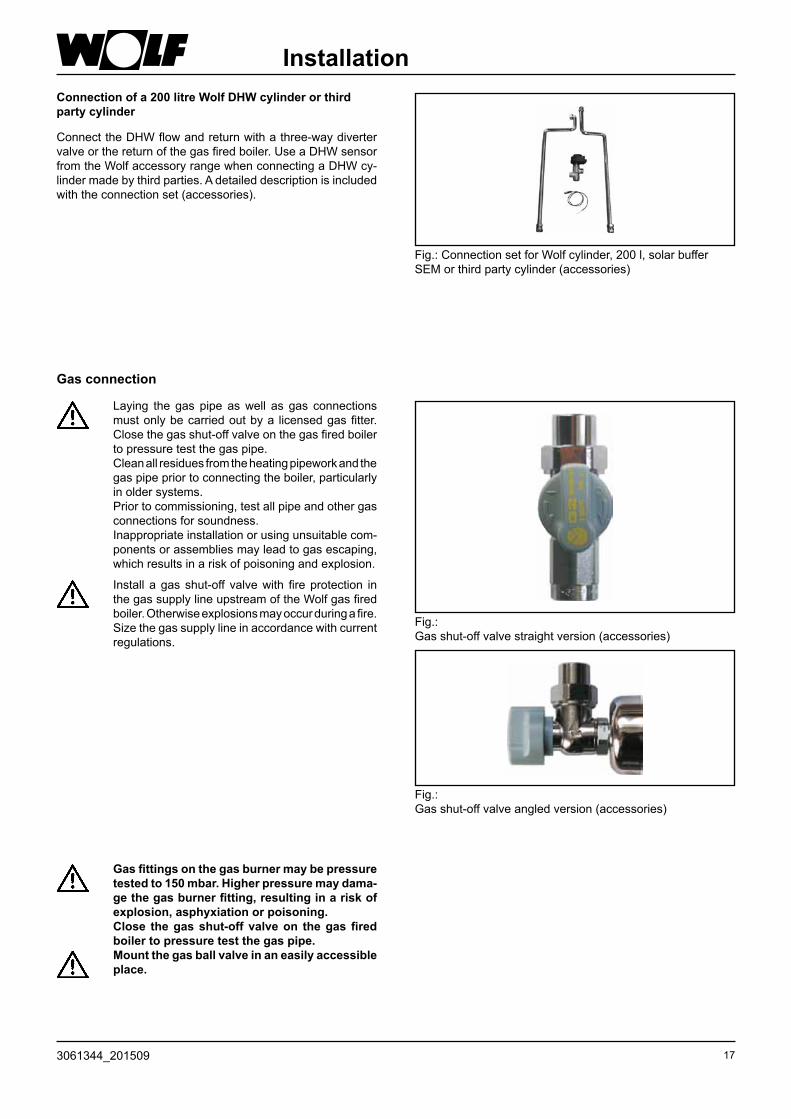
Connection of a 200 litre Wolf DHW cylinder or third party cylinder
Connect the DHW flow and return with a three-way diverter valve or the return of the gas fired boiler. Use a DHW sensor from the Wolf accessory range when connecting a DHW cy-linder made by third parties. A detailed description is included with the connection set (accessories).
Fig.: Connection set for Wolf cylinder, 200 l, solar buffer SEM or third party cylinder (accessories)
Gas connection
Laying the gas pipe as well as gas connections must only be carried out by a licensed gas fitter. Close the gas shut-off valve on the gas fired boiler to pressure test the gas pipe.
Clean all residues from the heating pipework and the gas pipe prior to connecting the boiler, particularly in older systems.
Prior to commissioning, test all pipe and other gas connections for soundness.
Inappropriate installation or using unsuitable com-ponents or assemblies may lead to gas escaping, which results in a risk of poisoning and explosion.
Install a gas shut-off valve with fire protection in the gas supply line upstream of the Wolf gas fired boiler. Otherwise explosions may occur during a fire. Size the gas supply line in accordance with current regulations.
Fig.: Gas shut-off valve straight version (accessories)
Fig.: Gas shut-off valve angled version (accessories)

18 3061344_201509
Installation of a balanced flue system
In t ight spaces, CO 2 value and f lue gas tempe -rature can be tested immediately downstream of the boiler at a connection adaptor with inspection piece (80/125 system) or alternatively at an inspection piece with connector (60/100 system).
The flue gas test ports must remain accessible to the relevant authorities, even after fitting the ceiling bezels.
NB
Fig.: Example: Balanced flue system
For concentric air/flue pipes (balanced flue systems), use only original Wolf components.
Please observe the technical information regarding balanced flue systems prior to installing the flue pipe or the ventilation air connection.
Different countries have different regulations. We would therefore recommend you contact the appro-priate authorities to check local requirements.
NB

193061344_201509
AFE1 eBUS
+ - 1 2a b
Netz Z A1
N
N
NL1L1 L1
1 2 1 21 2L1 L1L1 N NN
3 3 3 2 2 2
Power supply
Installation information, power supply
- Isolate the system from the power supply before opening the casing.
- Pivot the control unit to the side.- Open the terminal box.- Insert the strain relief into the holes provided.- Strip approx. 70 mm off the power supply cable insulation.- Push the cable through the strain relief and secure the strain
relief.- Pull the Rast5 plugs.- Terminate the appropriate cores at the Rast5 plugs.- Push the inserts back into the terminal box casing.- Push the Rast5 plugs back into their correct positions. Strain relief
F 3,15 A
Rast5 plugs
General notes
The power supply terminals are ‚live‘ even when the ON/OFF switch has been switched OFF.
The installation must be carried out by a licensed electrical contractor. Observe local regulations and those of the power supply company.
Terminal box
The control, regulating and safety equipment are fully wired and tested.You only need to connect the power supply and the external accessories.
Mains electrical connectionConnect the power supply permanently or with a safety plug (no plug connection in protective areas 1 and 2, i.e. near a bath or shower).
Provide the power supply via a mains isolator (e.g. fuse, heating system emergency stop), which ensures at least 3 mm contact separation for all poles.Flexible connecting cable, 3 x 1.0 mm² or solid cable, max. 3 x 1.5 mm².The plug must be accessible when using a power supply cable with safety plug. Flexible power supply cable 3 x 1.0 mm².
Power supply230 V AC/50Hz
Power supply, ext. accessories 230 V AC/50Hz/max. 300 VA
Programmable output230 V AC/50Hz
Programmable input zero volt Outside
temp. sensor
Data BUS(controller, radio clock, AF with radio clock, receiver, outside radio sensor)
Terminal box

20 3061344_201509
Power supply
DHW sensor connection
- When a cylinder is to be connected, the blue socket of the cylinder sensor must be connected to the blue plug of the control unit.
- Observe the cylinder installation instructions.
Fig.: Blue plug, cylinder sensor connection
Blue plug
Connection DHW circulation pump/ external accessories (230 V AC)
Insert the cable glands into the terminal box. Insert and secure the cable through the cable gland.
Connect the DHW circulation pump 230 V AC, which is part of the Wolf accessory range, to terminals L1, N and .
Fig.: Connection DHW circulation pump/external accesso-ries
Connection output A1 (230 V AC; 200 VA)
Insert the cable glands into the terminal box. Insert and secure the connecting cable through the cable gland. Connect the cable to terminals L1, N and .The parameters for output A1 are described in the table on the following page.
Fig.: Connection output A1
Changing a fuse
Isolate the condensing boiler from the power supply prior to changing a fuse. The ON/OFF switch on the boiler does not provide separation from the power supply.
Danger through ‚live‘ electrical components. Never touch electrical components or con-tacts as long as the condensing boiler has not been isolated from the power supply. Risk to life.
Fig.: Pivot the control unit forward; terminal box cover open
Fuse
Netz Z A1
N
N
NL1L1 L1
L1 L1L1 N NN
3
Netz Z A1
N
N
NL1L1 L1
L1 L1L1 N NN
3

213061344_201509
Code Explanation0 N/A
No activation of output A11 DHW circulation pump 100%
Controller (e.g. BM) activate output A1 when DHW is enabled.Output A1 is constantly activated when no controller is installed.
2 DHW circulation pump 50%Controller (e.g. BM) cycles output A1, when DHW is enabled. 5 minutes ON and 5 minutes OFF. Output A1 is cycled constantly in 5 minute intervals when no controller is installed.
3 DHW circulation pump 20%Controller (e.g. BM) cycles output A1, when DHW is enabled. 2 minutes ON and 8 minutes OFF. Output A1 is cycled constantly when no controller is installed.
4 Alarm outputOutput A1 is activated after a fault and expiry of 4 minutes.
5 Flame transmitterOutput A1 is activated after a flame has been recognised.
6 Cylinder primary pump (only for central heating boilers) (factory setting for A1)Output A1 is activated when the cylinder is heated up.
7 Ventilation damperOutput A1 is activated before each burner start. The burner will, however, only be enabled after input E1 has been closed. Important: In any case, input E1 must also be programmed as „Ventilation damper“! The feedback to input E1 must be made with a zero volt contact (24V).Otherwise, use an on-site relay for potential separation.
8 External ventilationOutput A1 is activated inverted to the gas combination valve.Switching off external ventilation equipment (e.g. extractor fan) during burner operation is only required, if the boiler is operated as open flue system.
9 External LPG valveOutput A1 is activated in parallel to the gas combination valve.
10 External pump Output A1 switches synchronously with the heating circuit pump (HKP). Use with, for example, system separation.
Power supplyThe functions of output A1 can be scanned and adjusted with Wolf control accessories with eBUS capability.The following functions can be allocated to output A1:
M
24
V2
30
VA
C
A1
N N
L1
L1
12
E1
ab

22 3061344_201509
Power supply
Digital Wolf controller connection (KM, SM1, SM2, MM und BM)
Only connect control units from the Wolf accessory range. Each accessory is supplied with its own connection diagram.Use a 2-core cable (cross-section > 0.5mm²) as connection between the control unit and the gas fired boiler.
Fig.: Digital Wolf controller connection (eBUS interface)
AF
E1
eB
US
+-
12
ab
12
12
12 2
Connection of outside temperature sensorThe outside temperature sensor may be connected to the terminal strip of the boiler connection AF, or the terminal strip of the BM.
Fig.: Connection of outside temperature sensor
AF
E1
eB
US
+-
12
ab
12
12
12
2
Fig.: Connection of room thermostat
Connection input E1 (24 V)
Connect the cable for input 1 at terminals E1 in accordance with the wiring diagram; first remove the jumper between a and b from the respective terminals.
AF
E1
eB
US
+-
12
ab
12
12
12
2
The functions of input E1 can be scanned and adjusted with Wolf controllers with eBUS capability. The following functions can be allocated to input E1:
Code Explanation0 No function
Input E1 is not taken into consideration by the control unit.1 Room thermostat
With open input E1, heating operation will be blocked (summer mode), independent of any digital Wolf control acces-sories.
2 Maximum thermostat or system pressure switchOptional connection for a maximum thermostat or system pressure switch. To enable the burner, input E1 must be closed. As long as the contact is open, the burner will remain blocked for DHW and central heating, incl. emissions test mode and frost protection.
3 Not allocated4 Flow switch
Optional connection for an additional water flow switch.After pump activation, input E1 must be closed within 12 seconds. Where this is not the case, the burner will be switched OFF, and fault 41 will be displayed.
5 Monitoring the ventilation damper See parameters of output A1, no. 7. ventilation damper.
8 Burner block (BOB))Operation without burnerContact closed, burnerblockedHeating circuit pump and cylinder primary pump in standard modeThe burner is enabled in emissions test mode and in frost protection modeOpening the contact enables the burner again

233061344_201509
Filling the system
Fig.: Automatic air vent valve on the heating circuit pump
Cap of the autom. air vent valve
Air vent screw
Fill the system and vent it properly, to safeguard the perfect function of the gas fired condensing boiler.
Before connecting the gas fired condensing boiler to the heating system, flush the entire system to remove residues such as welding pearls, hemp, putty, etc. from the pipework.
• With the boiler in a cold condition, fill the heating system slowly via the return, until 1.5 bar pressure is indicated. Inhibitors are not permissible.
• Check the entire system for water leaks.
• Fill the condensate siphon with water.
• Close the gas tap.
• Open the manual air vent valve.
• Open the cap of the automatic air-vent valve (on the hea-ting circuit pump) by one revolution, but do not remove the cap.
• Open all radiator valves. Open all flow and return valves on the gas fired condensing boiler.
• Fill the system to 1.5 bar pressure. In operation, the pressure gauge must indicate between 1.5 and 2.5 bar.
• Start the gas fired condensing boiler, set the heating water temperature selector into position „2“ (pump running, illumi-nated ring (status display) constantly green).
• Vent the pump; for this, briefly open and then retighten the air vent screw..
• Vent the heating circuit; for this, switch the condensing boiler several times ON and OFF.
• Top up with water when the system pressure drops seve-rely.
Close the manual air vent valve.
• Open the gas shut-off valve.
• Press the reset button.
Note: In constant operation, the heating circuit will be auto-matically vented via the heating circuit pump.
NB
NB
ON/OFF switch ThermomanometerReset button
Fig.: Control unit overview
Fig.: Manual air vent valve
Slightly crack open the manual air vent valve

24 3061344_201509
Commissioning
- Check the boiler and system for leaks. Prevent water leaks.
- Check location and seating of the installation.
- Check all connections and component joints for tightness.
If tightness cannot be ensured then there is a risk of water damage
- Check that all flue gas accessories have been correctly installed.
- Open the shut-off valves on flow and return.
- Open the gas shut-off valve.
Fig.: Shut-off valves
Flow shut-off valve
Return shut-off valve
Gas shut-off valve
- Prior to installation, ensure that the boiler matches the type of available gas. See the following table for permissible Wobbe index subject to gas type.
The initial start-up and operation of the boiler as well as the user instruction must only be carried out by a qualified contractor.
Natural gas H 15.0:WS= 11.4 -15.2 kWh/m³ = 40.9 - 54.7 MJ/m³
LPG PWS= 20.2 -24.3 kWh/m³ = 72.9 -87.3 MJ/m³
Table: Wobbe index subject to type of gas
- Switch ON the system ON/OFF switch on the control unit.
- Ignite and check the regular flame structure of the main burner.
- If the system water pressure falls below 1.5 bar, top up with water until a pressure of 1.5 to max. 2.5 bar has been achieved. ON/OFF switch ThermomanometerReset button
Fig.: Control unit overview

253061344_201509
Commissioning
Saving energy
- Instruct the customer about energy-saving options.
- Refer your customer to section „Information regarding energy-efficient operation“ in the operating instruc-tions.
- The illuminated ring shows a green colour, if the boiler starts correctly.
- Instruct the customer in the operation of the boiler. Complete the commissioning report and hand over the instructions to the customer.
Setting the BUS address (only for MM with SCOM interface or cascade)
When operating several boilers (number of boilers >1) in conjunction with a cascade module, set the eBUS address of each boiler in accordance with the table below.
BUS address setting:Hold down the reset button; after 5 seconds, the corresponding flashing code will be displayed (see table). Select the corresponding address with the DHW temperature rotary selector. Release the reset button again.
BUS address DHW rotary selector position Illuminated ring display
1 1 flashing red
2 2 flashing yellow
3 3 flashing yellow/red
4 4 flashing yellow/green
5 5 flashing green/red
0 6 flashing green (factory setting)
Illuminated ring
Fig.: Control unit overview

26 3061344_201509
Checking the gas supply pressureChecking the gas supply pressure Work on gas components MUST ONLY be pre-
formed by a registered gas fitter. Work which is carried out incorrectly may lead to gas escaping, resulting in a risk of explosion, asphyxiation or poisoning.
• Switch OFF the gas fired boiler. Open the gas shut-off val-ve.
• Pivot the control unit lid down. Unlock the casing lid with the l.h. and r.h. rotating locks.
Release the lower part of the casing lid and unhook at the top.
• To pivot the control unit, push in the tab on the r.h. side of the thermomanometer using a screwdriver.
• Pivot the control unit out.• Release the plug at test nipple and vent the gas supply
pipe.• Connect the differential pressure meter to „+“ at test port .
Connect „-“ against atmosphere
• Switch ON the ON/OFF switch.
• After starting the boiler, check the supply pressure at the differential pressure gauge.
Fig.: Check the gas supply pressure
Natural gas: If the supply pressure lies outside the 18 to 25
mbar range, adjustments must not be carried out and the boiler must not be taken into use.
NB
LPG: If the supply pressure lies outside the 25 to 45
mbar range, adjustments must not be carried out and the boiler must not be taken into use.
NB
Fig.: Push in the tab
Tab
Fig.: Open the rotating locks
rotating lock

273061344_201509
Filling the siphon / Checking the gas supply pressure
Filling the siphon
- Remove the siphon.
- Fill the siphon with water.
- Install the siphon.
Fig.: SiphonSiphon
Checking the gas supply pressure
• Switch OFF the ON/OFF switch. Close the gas shut-off valve.
• Remove the differential pressure gauge, and reseal the test port with its plug .
• Open the gas shut-off valve.
• Check the test nipple for gas leaks.
• Complete the enclosed notice and affix to the inside of the casing.
• Close the boiler.
Fig.: Shut-off valves
Flow shut-off valve
Return shut-off valve
Gas shut-off valve

28 3061344_201509
Displaying/ modifying control parameters
The control parameter can be modified or displayed via controller with eBUS capability. For procedures, check the operating in-structions of the relevant accessories.
To prevent damage to the heating system, cancel night setback when outside temperatures fall below -12 ° C. If this rule is not observed, ice may form on the flue outlet which may result in injury to individuals or material losses.
NBModifications must only the carried out by a recognised heating contractor or by Wolf cu-stomer service.
Incorrect operation can lead to system faults.Please note when using parameter GB 05 or A09 (frost protection/outside temperature), that frost protection is not safeguarded if you set temperatures lower than 0 °C. This can lead to heating system damage.
NB
NB
Settings of column 1 are suitable for control accessories ART and AWT.Settings of column 2 are suitable for Wolf control systems with BM (programming unit)
1 2 Parameter Unit Factory setting
min max
GB01 HG01 Flow temperature hysteresis K 8 5 30HG02 Lower fan speed
Min. fan speed in %% CGB-11: 27
CGB-20: 27 CGB-24: 30
27 100
HG03 Upper fan speed DHWMax. fan speed in % for DHW
% CGB-11: 100 CGB-20: 100 CGB-24: 98
27 100
GB04 HG04 Upper fan speed central heatingMaximum fan speed in % for central heating
% CGB-11: 70 CGB-20: 82 CGB-24: 82
27 100
GB05 A09 Frost protection outside temperatureWith connected outside temperature sensor andinsufficient temperature pump ON
°C 2 -10 10
GB06 HG06 Heating circuit pump mode 0 → Pump ON in winter mode 1 → Pump ON when the burner is ON
0 0 1
GB07 HG07 Heating circuit pump run-on timeHeating circuit pump run-on time in heating mode in min.Heating circuit pump run-on time in heating mode in min.
min 1 0 30
GB08 HG08 or HG22
Maximum set flow temperatureApplies to heating mode
°C 80 40 90
GB09 HG09 Cycle blockapplies to heating mode
min 7 1 30
HG10 e Bus address Bus address of boiler (display only)
0 0 5
HG11 DHW quick start-upTemperature of plate heat exchanger in summer mode(suitable for combi-boilers only)
°C 10 10 60
HG12 Gas typenot assisted
0 0 1
GB13 HG13 Input E1Input E1 (24 V)Various functions can be allocated to input E1.See chapter „Connection input E1“
1 Roomther-mostat
0 5
GB14 HG14 Output A1 (230VAC)Various functions can be allocated to output A1.See chapter „Connection output A1“
6 Cylinder pri-mary pump
0 9
GB15 HG15 DHW cylinder hysteresisSwitching differential for cylinder reheating
5 1 30
GB16 HG16 Minimum pump speed, heating mode % CGB-11: 27 CGB-20: 48 CGB-24: 48
20 100
GB17 HG17 Minimum pump speed, heating mode % CGB-11: 56 CGB-20: 77 CGB-24: 82
20 100
HG21 Minimum boiler water temperature TK-min °C 20 20 90

293061344_201509
Adjusting the maximum outputCGB-11/CGB-20/CGB-K-20/CGB-24/CGB-K-24Output setting (parameter GB04)
The output setting can be modified with Wolf control accessories with eBUS capability.The heating output will be determined by the gas fan speed. By reducing the gas fan speed in accordance with the table, the maximum output will be matched (at 80/60 °C) to natural gas H and LPG.
Limiting the maximum output relative to a flow/return temperature of 80/60 °C
Settings for parameter GB04 with Wolf connection accessories with eBUS capability in [%]
Max
imum
out
put i
n kW
25
5,0
4,0
3,0
6,0
7,0
8,0
9,0
10,0
11,0
12,0
13,0
14,0
15,0
16,0
17,0
18,0
19,0
20,0
21,0
22,0
23,0
24,0
25,0
30 35 40 45 50 55 60 65 70 75 80 85
CGB-11
CG
B-2
4
CGB-20
Table: Output setting
CGB-24/CGB-K-24
Heating output (kW) 7,1 8 9 10 11 12 13 14 15 16 17 18 19 20 21 22 23Display value (%) 30 32 35 38 42 45 47 52 55 57 61 64 67 70 73 77 82
CGB-20/CGB-K-20
Heating output (kW) 5,6 6 7 8 9 10 11 12 13 14 15 16 17 18 19Display value (%) 27 29 33 37 41 45 49 54 57 62 66 70 74 78 82
CGB-11
Heating output (kW) 3,3 4 5 6 7 8 9 10Display value (%) 26 29 35 42 49 56 63 70

30 3061344_201509
Selecting the pump stage
In the delivered condition, the three-stage pump is set to stage 2 (centre position).You can select the pump stage manually.
• Check with the diagram „Residual boiler head“ in chapter „Specification“, whether this setting is correct for your sy-stem.
The gas fired condensing boiler is either equipped with a three-stage pump or with a modulating pump. If a modulating pump is installed, see chapter „Modulating pump“.
- Shut down the boiler at the ON/OFF switch.
- Remove the cover lid.
- Unlock the control unit housing and pivot it out.
- At the switch, select the required pump stage.Fig.: Switching stages at the three-stage heating circuit pump
stage 1
stage 2
stage 3
Pump stage selector
Fig.: Selector at the three-stage heating circuit pump
The following settings are recommended:
Ensure that the switch correctly clicks into place and does not remain in an intermediate position.
Select the next lower pump stage when flow noise is excessive.
Select the next higher pump stage, if individual radiators remain cold, even though their valves are open.
NB
NB
NB
Boiler Pump stage
Central heating boiler 1, 2, 3
Central heating boiler with cyl. 1, 2, 3
Combi boiler 2, 3

313061344_201509
Testing the combustion parametersTest the combustion parameters with the boiler closed.
Testing the combustion air
- Remove the screw from the r.h. test port.
- Open the gas shut-off valve.
- Insert the test probe.
- Start the gas fired condensing boiler and turn the heating water temperature selector to the emissions test symbol (illuminated status display ring flashes yellow).
- Test the temperature and CO2 value.
The balanced flue pipe is not sound, if the CO2 content is > 0.3 %; rectify the leak.
- After the test has been completed, switch off the boiler, remove the test probe and close the test port. Ensure the screws seal tightly.
Testing the flue gas parameters
Flue gas can escape into the installation room, if the test port is not sealed. This results in a risk of asphyxiation.
- Remove the screw from the l.h. test port.
- Open the gas shut-off valve.
- Start the gas fired condensing boiler and turn the tempera-ture selector to the emissions test symbol (illuminated status display ring flashes yellow).
- Insert the test probe.
- Test the flue gas values.
- After the test has been completed, remove the test probe and close the test port. Ensure the screws seal tightly.
NB
Fig.: Shut-off valves
Gas shut-off valve
ON/OFF switch Thermomanometer
Fig.: Control unit overview
Fig.: Test ports
Test port „Air supply“Test port „Flue gas“
32 3061344_201509
CO2 settings
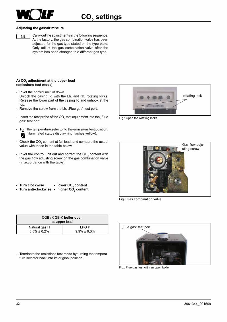
- Terminate the emissions test mode by turning the tempera-ture selector back into its original position.
- Turn clockwise - lower CO2 content- Turn anti-clockwise - higher CO2 content
Gas flow adju-sting screw
Fig.: Gas combination valve
Adjusting the gas:air mixture
Carry out the adjustments in the following sequence: At the factory, the gas combination valve has been adjusted for the gas type stated on the type plate. Only adjust the gas combination valve after the system has been changed to a different gas type.
NB
A) CO2 adjustment at the upper load (emissions test mode)
- Pivot the control unit lid down. Unlock the casing lid with the l.h. and r.h. rotating locks.
Release the lower part of the casing lid and unhook at the top.
- Remove the screw from the l.h. „Flue gas“ test port.
- Insert the test probe of the CO2 test equipment into the „Flue gas“ test port.
- Turn the temperature selector to the emissions test position, (illuminated status display ring flashes yellow).
- Check the CO2 content at full load, and compare the actual value with those in the table below.
- Pivot the control unit out and correct the CO2 content with the gas flow adjusting screw on the gas combination valve (in accordance with the table).
CGB / CGB-K boiler openat upper load
Natural gas H 8,8% ± 0,2%
LPG P 9,9% ± 0,3%
Fig.: Open the rotating locks
rotating lock
Fig.: Flue gas test with an open boiler
„Flue gas“ test port

333061344_201509
CO2 settings
- Restart the boiler by pressing the „Reset button“.
- Check and correct (if required) the CO2 content approx. 20 s after burner start with the CO2 meter, by fine adjusting the zero point adjusting screw in accordance with the table below. Make this adjustment within 120 s after burner start. If necessary, repeat the start phase for setting purposes by pressing the „Reset button“.
- Turn clockwise - higher CO2content.
- Turn anti-clockwise - lower CO2content.
B) CO2 adjustment at the lower load (soft start)
Fig.: Gas combination valve
Zero point adju-sting screw
- Switch the boiler OFF and close the test ports and hose nipple; check for leaks.
D) Completing the adjustments
C) Checking the CO2 adjustment
- After completing the work, refit the casing lid and check the CO2 value with the boiler closed.
During the initial start-up, the EC emissions can reach 200 ppm for the first hours, as binding agents from the insulation combust.
Observe the CO emissions whilst making CO2 ad-justments. The gas combination valve is incorrectly adjusted, if the CO value lies >200ppm, when the CO2 value is correct. In that case, take the following steps::
- Fully insert the zero point adjusting screw
- open the zero point adjusting screw 3 revolutions for natural gas, and 2 revolutions for LPG.
- Repeat the adjusting process from section A).
- The boiler is correctly adjusted, when the CO2 value corre-sponds with those in the adjacent table.
NB
CGB / CGB-K boiler openat lower load
Natural gas H 8,8% ± 0,2%
LPG P 10,8% ± 0,5%
CGB / CGB-K boiler closedat lower load
Natural gas H 9,0% ± 0,2%
LPG P 11,1% ± 0,5%
CGB / CGB-K boiler closedat upper load
Natural gas H 9,0% ± 0,2%
LPG P 10,1% ± 0,3%
Fig.: Flue gas test with a closed boiler
Test port „Flue gas“

34 3061344_201509
Commissioning report
1.) Gas type Natural gas H LPG Wobbe index kWh/m³ Net calorific value kWh/m³
2.) Gas supply pressure checked?
3.) Gas soundness test carried out?
4.) Balanced flue system checked?
5.) Water connections checked for leaks?
6.) Fill the siphon
7.) Vented boiler and system?
8.) System pressure 1.5 - 2.5 bar?
9.) Entered type of gas and output onto label?
10.) Function test carried out?
11.) Flue gas test: Gross flue gas temperature tA [°C] Ventilation air temperature tL [°C] Net flue gas temperature (tA - tL ) [°C] Carbon dioxide content (CO2) or oxygen content (O2) % Carbon monoxide content (CO) ppm
12.) Casing fitted?
13.) System user trained, tech. docs. handed over?
14.) Confirm commissioning?
Commissioning steps Test values or confirmation

353061344_201509
Technical conversion optionsfor gas fired condensing boiler CGB
Via conversion sets, Wolf offer you the option of matching your gas fired condensing boiler to changing conditions.
Conversion to alternative DHW versions:
1) A conversion set is only required, if you no longer possess the conversion label.The conversion is detailed in chapter „Conversion of combi boilers to boilers with cylinder“.
from to Set
Central heating boilerBoiler
Boiler with cylinder ...SW-120 for finished surfaces Boiler with third party cylinder
86 02 714 86 02 715
Central heating boilerBoiler with cylinder
Combi boiler (only CGB-20)Heiztherme
86 02 66886 02 708
Boiler with cylinderCombi boiler
Combi boiler (only CGB-20)Boiler
86 02 66886 02 708
Combi boiler Boiler with cylinder 86 02 708 1)
Conversion to other gas types:
from tu CGB-11 CGB-(K)-20 CGB-(K)-24
Natural gas H LPG P - 86 10 593 86 10 927
LPG P Natural gas H - 86 10 592 56 10 928
BoilerGas type conversion High limit safety cut-out STB
Gas type Gas restrictor Flue gas STB Combustion cham-ber STB
CGB-11 H Green 43017 20 523 27 41 063 -
CGB-(K)-20H Orange 580
17 20 53227 41 063 -
LPG Green 43017 20 523
CGB-(K)-24H White 780
17 20 522Designationgreen dot
27 44 089
27 41 068LPG Red 510
17 20 520
36 3061344_201509
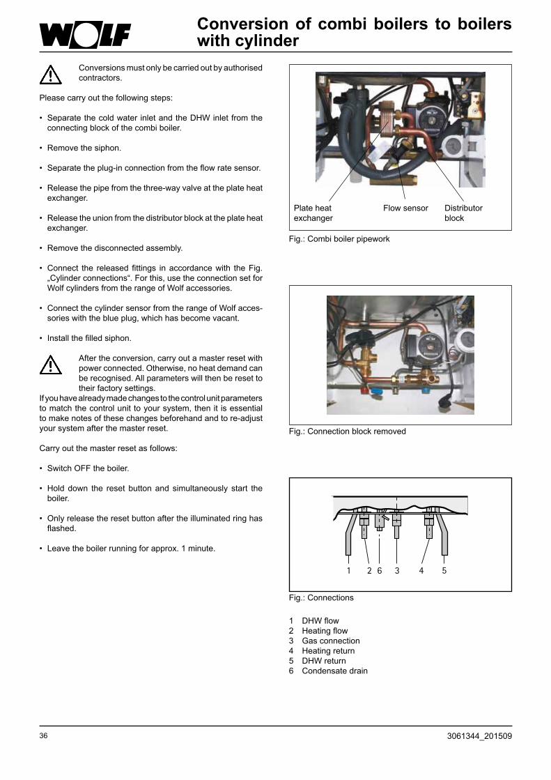
Conversion of combi boilers to boilers with cylinder
Conversions must only be carried out by authorised contractors.
Please carry out the following steps:
• Separate the cold water inlet and the DHW inlet from the connecting block of the combi boiler.
• Remove the siphon.
• Separate the plug-in connection from the flow rate sensor.
• Release the pipe from the three-way valve at the plate heat exchanger.
• Release the union from the distributor block at the plate heat exchanger.
• Remove the disconnected assembly.
• Connect the released fittings in accordance with the Fig. „Cylinder connections“. For this, use the connection set for Wolf cylinders from the range of Wolf accessories.
• Connect the cylinder sensor from the range of Wolf acces-sories with the blue plug, which has become vacant.
• Install the filled siphon.
After the conversion, carry out a master reset with power connected. Otherwise, no heat demand can be recognised. All parameters will then be reset to their factory settings.
If you have already made changes to the control unit parameters to match the control unit to your system, then it is essential to make notes of these changes beforehand and to re-adjust your system after the master reset.
Carry out the master reset as follows:
• Switch OFF the boiler.
• Hold down the reset button and simultaneously start the boiler.
• Only release the reset button after the illuminated ring has flashed.
• Leave the boiler running for approx. 1 minute.
Fig.: Connections
1 DHW flow2 Heating flow3 Gas connection4 Heating return5 DHW return6 Condensate drain
Fig.: Connection block removed
Flow sensorPlate heatexchanger
Distributor block
Fig.: Combi boiler pipework
1 2 6 3 4 5

373061344_201509
MaintenanceSafety instructions
The following symbols are used in conjunction with these important instructions concerning personal safety as well as operational reliability.
„Safety instructions“ are instructions with which you must comply exactly, to prevent injury and material losses.
Danger through ‚live‘ electrical components.Please note: Switch OFF the ON/OFF switch before removing the casing.
Never touch electrical components or contacts when the ON/OFF switch is in the ON position. This brings a risk of electrocution, which may result in injury or death.
The main supply terminals are ‚live‘ even when the ON/OFF switch is in the OFF position.
This indicates technical instructions which you must observe to prevent material losses and boiler malfunctions.
NB
Fig.: Terminal box:Danger from electric power
Fig.: Ignition transformer, high voltage ignition electrode, combustion chamberDanger through ‚live‘ electrical components; danger through hot components
General notes
Maintenance work must only be carried out by a qualified heating contractor. Regular maintenance and the exclusive use of ori-ginal Wolf spare parts are necessary preconditions for trouble-free operation and a long service life. We therefore recommend you arrange a mainte-nance contract with a local heating contractor.
Fig.: Gas combination valveRisk of electrical shock, risk of poisoning and explosion from escaping gas
Fig.: Gas connection: Escaping gas may cause poisoning or the risk of explosion

38 3061344_201509
Maintenance
- Unlock the casing lid with the l.h. and r.h. rotating locks. Release the lower part of the casing lid and unhook at the top.
The mains terminals are ‚live‘ even when the ON/OFF switch has been switched OFF.
- Disconnect the system from the power supply.
- Pivot the control unit lid down. Switch OFF the boiler at the ON/OFF switch.
Close the gas shut-off valve.
rotating lock

393061344_201509
Maintenance
- Lift the combustion chamber.
- Pull out the locking clip.
- Crack open the gas supply connection.
- Pull the control hose off the mixing chamber.
Danger of burning
Several components may be hot. Let these cool down or wear gloves.

40 3061344_201509
Maintenance- Fit the cleaning tray.
- Pivot the combustion chamber out.
- Pull the plug off the gas fan.
- Pull the plugs off the ionisation and the ignition electrodes.

413061344_201509
Maintenance
Visual burner gasket check
Lubricate the burner gasket with Wolf silicone grease or replace and lubricate.
- Rotate the combustion chamber pot and remove down-wards.
- Remove the combustion chamber lid upwards.
- Open the retaining tabs.

42 3061344_201509
Maintenance
- When you notice a loss of water, check the expansion vessel inlet pressure and increase it, if required, to 0.75 bar. The heating circuit must be at zero pressure.
- Clean the condensate pan.
- Clean the heat exchanger with a brush.
Versions with coated heat exchanger must only be cleaned with a plastic brush.

433061344_201509
Maintenance- Replace the upper and lower combustion chamber gasket;
lubricate the new gaskets with silicone grease.
- Lubricate the combustion chamber seat.
- Replace the monitoring electrode. Check and replace the ignition electrode, if necessary.
Visual insulation checkreplace, if broken

44 3061344_201509
Maintenance
- Replace the combustion chamber lid on the combustion chamber and secure with locking tabs.
Assembly
- Install the combustion chamber pot.
- Push the plug back onto the gas fan.
- Push the plugs back onto the ionisation and the ignition electrodes.
NB
453061344_201509
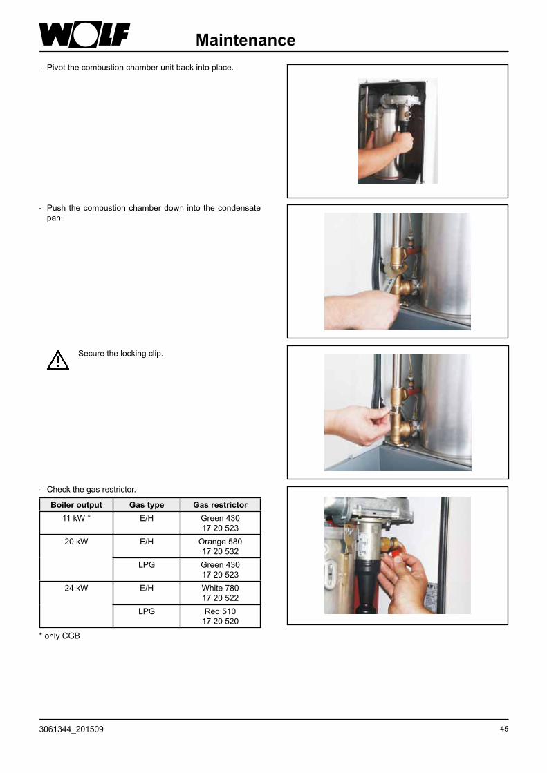
Maintenance- Pivot the combustion chamber unit back into place.
- Push the combustion chamber down into the condensate pan.
Secure the locking clip.
- Check the gas restrictor.
* only CGB
Boiler output Gas type Gas restrictor11 kW * E/H Green 430
17 20 52320 kW E/H Orange 580
17 20 532LPG Green 430
17 20 52324 kW E/H White 780
17 20 522LPG Red 510
17 20 520
46 3061344_201509
Maintenance
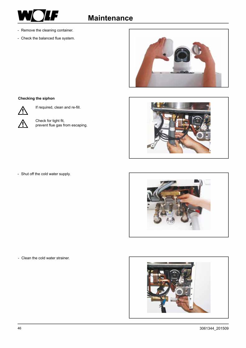
- Check the balanced flue system.
- Remove the cleaning container.
- Clean the cold water strainer.
- Shut off the cold water supply.
Checking the siphon
If required, clean and re-fill.
Check for tight fit,prevent flue gas from escaping.

473061344_201509
Maintenance
Fig.: Non-return valve
CGWCGS
- If the DHW output is too low, descale the DHW heat ex-changer and the non-return valve.
- Reopen the cold water tap.

48 3061344_201509
Maintenance
Test run
Completing the adjustments
- Reset the MCBs.- pen the gas tap.- Switch ON the boiler.- Set the program selector to emissions test mode.
- Switch the boiler OFF and close the test ports and hose nipples; check for leaks.
- Fit the casing.
Flue gas test
Re-adjust the CO2 content, if required(see next page)
Carrying out a ventilation test
Check LAF for soundness, if the CO2 value > 0.2%.
Emissions test mode position

493061344_201509
Maintenance
Maintenance requires the following:
1 Maintenance set CGB-11/20/24 Art.-Nr. 86 03 017
1 Cleaning set Art.-Nr. 86 03 194
1 Test equipment for BImSchV test [Germany]
We recommend you have the following as part of your service kit:
1 Insulation CC top part Art.-Nr. 86 03 041
1 Gasket for flue gas temperature controller Art.-Nr. 86 03 033
1 Sealing collar for test port Art.-Nr. 39 03 143
1 Silicone grease 10 g tube Art.-Nr. 86 02 264
1 Burner gasket Art.-Nr. 39 03 121
1 Flow temperature sensor Art.-Nr. 86 03 038
1 Flue gas temperature controller Art.-Nr. 86 03 058
1 Flue gas temperature controller Art.-Nr. 86 01 869
1 Ignition electrod Art.-Nr. 86 03 061
1 Protective anode for enamelled cylinder Art.-Nr. 24 45 128
Checking control accessories
Fig.: AWTFig.: BM
- The display must show BUS connection .
BUS connection
50 3061344_201509
Maintenance
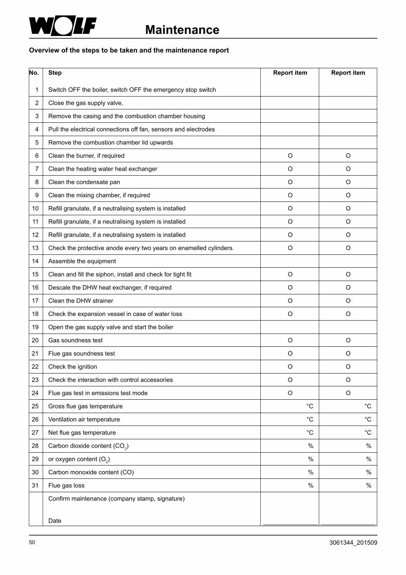
1 Switch OFF the boiler, switch OFF the emergency stop switch
2 Close the gas supply valve,
3 Remove the casing and the combustion chamber housing
4 Pull the electrical connections off fan, sensors and electrodes
5 Remove the combustion chamber lid upwards
6 Clean the burner, if required O O
7 Clean the heating water heat exchanger O O
8 Clean the condensate pan O O
9 Clean the mixing chamber, if required O O
10 Refill granulate, if a neutralising system is installed O O
11 Refill granulate, if a neutralising system is installed O O
12 Refill granulate, if a neutralising system is installed O O
13 Check the protective anode every two years on enamelled cylinders. O O
14 Assemble the equipment
15 Clean and fill the siphon, install and check for tight fit O O
16 Descale the DHW heat exchanger, if required O O
17 Clean the DHW strainer O O
18 Check the expansion vessel in case of water loss O O
19 Open the gas supply valve and start the boiler
20 Gas soundness test O O
21 Flue gas soundness test O O
22 Check the ignition O O
23 Check the interaction with control accessories O O
24 Flue gas test in emissions test mode O O
25 Gross flue gas temperature °C °C
26 Ventilation air temperature °C °C
27 Net flue gas temperature °C °C
28 Carbon dioxide content (CO2) % %
29 or oxygen content (O2) % %
30 Carbon monoxide content (CO) % %
31 Flue gas loss % %
Confirm maintenance (company stamp, signature) Date
Overview of the steps to be taken and the maintenance report
No. Step Report item Report item

513061344_201509
Maintenance
O O O O O O
O O O O O O
O O O O O O
O O O O O O
O O O O O O
O O O O O O
O O O O O O
O O O O O O
O O O O O O
O O O O O O
O O O O O O
O O O O O O
O O O O O O
O O O O O O
O O O O O O
O O O O O O
O O O O O O
°C °C °C °C °C °C
°C °C °C °C °C °C
°C °C °C °C °C °C
% % % % % %
% % % % % %
% % % % % %
% % % % % %
Report item Report item Report item Report item Report item Report item

52 3061344_201509
Modulating pump (class A)
Function descriptionmodulating pump(modulating pump not for 24 kW)(class A)
In heating mode: The heating circuit pump modulates in proportion to the burner output, i.e. at max. burner load, the pump operates with the maximum selected pump speed for „Heating mode“. At minimum burner load, the pump operates with the minimum selected pump speed for „Heating mode“. In other words, the burner and pump output are regulated subject to the required heating load. The power consumption is reduced by the pump modulation.
In DHW mode: The heating circuit pump will not modulate, but operates con-stantly with the selected „DHW“ pump speed (see table).
In standby mode: The heating circuit pump operated with the selected „Standby mode“ pump speed.
Factory settings „Pump speed“ Boiler Heating mode DHW StandbyMax. Min.
CGB-11 56 % 27 % 56 % 20 %CGB-(K)-20 77 % 48 % 74 % 20 %CGB-(K)-24 82 % 48 % 90 % 20 %
Residual height of the modulating pump (class A)
Res
idua
l hei
ght i
n m
bar
Flow rate in l/h
0
50
100
150
200
250
300
0 100 200 300 400 500 600 700 800 900 1000 1100 1200 1300 1400
Fördermenge [l/h]
Res
tförd
erhö
he in
[mba
r]
27 %10W
74 %43W
82 %51 W
20 %9 W
77%44W
100 %69 W
56 %25W
48 %20W
90 %65W

533061344_201509
3-stage-pumpResidual height of the three-stage pump
Res
idua
l hei
ght i
n m
bar
Flow rate in l/h
Solution Problem SolutionIndividual radiators are not getting properly warm. i.e. reduced
Create hydraulic balancing, flow rate of hotter radiators.
During spring and autumn, the required room temperature is not reached.
Increase set room temperature at controller, e.g. from 20 to 25 °C.
Selected room temp. is not reachedwhen outside temperatures are very low.
Select a steeper heating curveat the controller, e.g. from 1.0 to 1.2.

54 3061344_201509
Design informationBalanced flue system
B23
B33C13x
C53 C93x C43x C83x
C53x
C33x
I IIII IIIII IIIII IIII IIIII IIII IIIII IIIII IIII IIIII IIIII IIII IIIII IIII IIIII IIIII IIII IIIII IIIII IIII IIIII IIIII
I IIIII IIII IIIII IIIII III
IIIIIIIIIIII
II
II
II
IIII
I
III
IIIIII
IIII
IIIIIIIIIIIII
C33x C43x
C83x C93x C33x B33
C13x

553061344_201509
Balanced flue system
Design information
Versions as condensing boilers up to 24 kW
Maximum length 1) 2)
[m]
DN60/100 DN80/125
B23 Flue inside a duct and combustion air directly through the boiler (open flue) + 2 m horizontal connecting line - 30
B33 Flue DN 80 inside a duct + 2 m horizontal concentric connection line (open flue) 13 30
B33 Connection to a moisture-resistant flue gas chimney with horizontal concentric connection pipe (open flue)
Calculation toDIN EN 13384
(MRC manufacturer)
C13x Horizontal roof outlet through a pitched roof, not for CGB-11 with DN 60/100 (balanced flue - on-site dormer) 9 10
C13x External wall outlet (balanced flue) (for DE < 11 kW) 5 10
C33x Vertical concentric roof outlet through a pitched or flat roof, vertical concentric balanced flue for installation in a duct (balanced flue) 9 22
C43x Connection to a moisture-resistant balanced flue chimney (MRC) maximum pipe length from the centre of the boiler bend to the connector 2 m (balanced flue)
Calculation toDIN EN 13384
(MRC manufacturer)
C53 Connection to the flue in a duct and ventilation air supply through the external wall - 30
C53x Connection to a flue on an external wall (balanced flue) - 22
C83x Connection to a flue in a duct and ventilation air supply through an external wall (balanced flue) - 30
C83x Concentric connection to a moisture-resistant flue gas chimney and combustion air through an outside wall (balanced flue)
Calculation toDIN EN 13384
(MRC manufacturer)
C93x Vertical flue for duct installation DN 80 rigid/flexible + 2 m horizontal concentric connecting line 13 22
1) Available fan draught: 90 Pa (The maximum length corresponds to the total length from the appliance to the flue terminal)
Note: Systems C33x and C83x are also suitable for ins-tallation in garages. Where necessary, adapt the installation examples to the relevant Building Regulations and requirements of your country/region. Discuss any questions relating to the installation, particularly of inspection pieces and ventilati-on apertures (ventilation generally required above 50 kW output) prior to installation with your local heating engineer/flue gas inspector.
The length dimensions refer to concentric balanced flue and flues, specifically only to original Wolf components.
Balanced flue systems DN60/100 and DN80/125 are certified as systems together with Wolf gas condensing boilers.
The following balanced flue or flues with CE-0036-CPD-9169003 certification may be used:- Flue DN80- Concentric balanced flue DN60/100 and DN80/125- Flue DN110- Concentric balanced flue (on an external wall) DN80/125- Flue, flexible DN83The necessary type plates are supplied with the respective WOLF accessory.Observe all additional installation instructions included with accessories.
56 3061344_201509
With low outside temperatures, the water vapour contained in the flue gas may condense and freeze on the balanced flue. This ice may fall from the roof causing injuries or material losses. Prevent ice from falling through on-site measures, e.g. the installation of a snow catcher grille.
If fire resistance is not required for the ceiling, route the lines for the combustion air supply and the flue gas from the top edge of the ceiling to the roof skin inside a duct made from non-combustible, rigid materials or inside a protective metal pipe (mechanical protection). There is a risk of fires spreading, if these requirements are ignored.
General notes
Particularly for safety reasons, use only original Wolf components for concentric balanced flues and flues.
Where necessary, adapt the installation examples to the relevant Building Regulations and requirements of your country/region. Discuss any questions relating to the installation, particularly regarding the inspection components and ventilation apertures, prior to installation with your local heating engineer/flue gas inspector.
Gas fired condensing boilers with a balanced flue outlet above the roof may only be installed in attics or in rooms, where the ceiling also forms the roof or where only the roof construction is located above the ceiling.
If the balanced flue crosses different floors, route the pipes outside the boiler room inside a duct with a fire resistance of at least 90 min., and in living space of low height with a resistance of at least 30 min. Fire may spread if these instructions are not observed.
The following applies to gas fired boilers with a balanced flue above the roof, where only the roof structure lies above the ceiling:
If fire resistance is required for the ceiling, the pipes for combustion air supply and flue gas exhaustion running between the top edge of the ceiling and the roof skin must be run inside a liner that provides the same fire resistance and is constructed from non-combustible materials. There is a risk of transferring fires, if these requirements are ignored.
Secure the balanced flue or flue outside ducts with spacer pipe brackets with a minimum clearance of 50 cm from the flue outlet or upstream/downstream of deviations to prevent the pipe joints being pulled apart. Flue gas may escape, if this rule is not observed. Furthermore, equipment damage may result.
Design information
A clearance between the concentric balanced flue and combustible materials or components is not required, as no temperatures higher than 85 °C will occur at the rated output.If only a flue is installed, maintain the clearances specified by DVGW/TRGI 2008 [or local regulations].
Balanced flues without ducts must not be routed through other rooms, otherwise there would be a risk of fire spreading, and no mechanical protection would be provided.
The combustion air must not be drawn from chimneys that used to carry flue gases from oil or solid fuel boilers.
NB

573061344_201509
The electronic flue gas temperature limiter switches the gas fired condensing boiler off when the flue gas temperature exceeds 110 °C.
The boiler restarts when the reset button is pressed.
The rated boiler output in heating mode must be reduced to below 11 kW, if the gas fired condensing boiler is installed with a balanced flue routed over an external wall (for appropriate measures, see chapter „matching the maximum output“ on page 24).
Flue gas temperature limiter
The clear cross-section of flues must be able to be inspected. Therefore, install an inspection and/or test aperture inside the boiler room; agree suitable arrangements with your local heating engineer.
Flue connections are created using couplings and gaskets. Always arrange couplings against the condensate flow direction. Install the balanced flue with a slope of at least 3° towards the gas fired condensing boiler. Install spacer clamps to secure the location (see installation example).
Connection to the balanced flue
The calculated length of the balanced flue system or the flue is derived from the straight pipe length and the length of the pipe bends.
Example for a system comprising 60/1001)
Length of straight balanced flue 1.5 m L = straight length + bend length1 x 87° bend = 1.5 m L = 1.5 m + 1 x 1.5 m + 2 x 1.3 m2 x 45° bends = 2 x 1.3 m L = 5.6 m
Calculating the balanced flue length
Note: To avoid the fresh air supply and flue gas exhaustion influencing each other above the roof, we recommend you maintain a minimum clearance of 2.5 m between the inlet and outlet.
1) Length equivalence of the system:
Design information
60/100 80/12587°-bend 1,5 m 3 m45°-bend 1,3 m 1,5 m
58 3061344_201509
Connection to a moisture-resistant balanced flue chimney (MRC), flue gas chimney or flue gas system, type C 43xChimneys and flue gas systems must be certified for condensing combustion equipment (DIBI certification, CE [or local equivalent]). Sizing via calculation tables subject to flue gas category. In addition to the boiler connection bend or tee piece, up to two 90° diversions may be installed. Operation with positive pressure may require an appropriate permit.
Straight balanced flues may be up to 2 m long, when connecting the system to a balanced flue chimney.The balanced flue chimney MRC must be certified [in Germany] by the DIBT - Deutsches Institut für Bautechnik or must be CE-designated; it must also be approved for condensing operation with positive pressure.
Connection to a moisture-resistant flue gas chimney of a flue gas system type B33 for open flue operationStraight balanced flues may be up to 2 m long, when connecting the system to a flue gas chimney. In addition to the boiler connection bend, up to two 90° diversions may be installed.The flue gas chimney must be certified [in Germany] by the DIBT or must be CE-designated; it must also be approved for condensing operation.The flue outlet should be obtained from the chimney manufacturer, if necessary.The air vents to the boiler room must be free of obstructions.
Connection to a moisture-resistant flue type B23 for open flue operation
The straight, horizontal flue must not be longer than 2 m. In addition to the boiler connection bend, up to two 90° diversions may be installed into the horizontal flue.For this version, observe the ventilation requirements for boiler rooms acc. to DVGW-TRGI.
The straight, horizontal flue must not be longer than 2 m. For horizontal air supply pipes, a maximum length of 2 m is recommended. Observe special requirements for flues, that are not surrounded by combustion air, acc. to DVGW-TRGI 2008and all locally applicable combustion orders.
Connection to a moisture-resistant flue type C53, C83x for balanced flue operation
Connection to a combustion air and flue system type C63x that is not tested together with the gas combustion equipmentOriginal Wolf components are designed for long-term use, are designated with the DVGW quality seal and are matched for use with Wolf gas fired condensing boilers. When using third party equipment that is only DIBT certified or CD-designated, the installer will be responsible for the correct sizing and perfect function of such systems. Faults, material losses and injuries resulting from incorrect pipe lengths, excessive pressure drop, premature wear with escaping flue gas and condensate or incorrect function, e.g. through components working themselves loose, are excluded from our warranty, if non-approved third party equipment is used.
Straight balanced flues may be a maximum of 2 m long, when connecting the system to a combustion air supply and a separate flue. In addition to the boiler connection bend, up to two 90° diversions may be installed.The chimney must be free from contamination, if the combustion air is drawn from the chimney.
These boilers are suitable for multiple connection to a common chimney in accordance with the DVGW Code of Practice G 635. An internal flue gas return facility is used to prevent a return flow of flue gas. The plumb clearance between two gas fired boilers must be at least 2.5 m. The installed flue gas system must be certified for multiple connection to a common chimney. A verification is required for the correct sizing in accordance with fire protection regulations.
Multiple connection to a common chimney
Design information

593061344_201509
Design information
4 417 11
12
13
14
16
3
915
1
28
9 4
8
10
3
4
3
5
4
5
3
5
4
1 1 1
Vertical balanced flue routing (examples) system DN60/100
Flue gas < 120 °C
C93x
6
7
NB Install the horizontal line with > 3° slope towards the boiler
1 Gas fired condensing boiler
2 Balanced flue incl. inspection aperture (250 mm long)
3 Separator DN60/100 (slide coupling) if required
4 Balanced flue DN60/100 500 mm 1000 mm 2000 mm
5 Balanced flue, vertical DN60/100 (roof outlet for flat or pitched roofs) L = 1200 mm L = 1200 mm ... 1700 mm
6 Universal tile for pitched roof 25/450
7 Flat roof collar
8 Bend 45° DN60/100
9 Inspection elbow DN60/100
10 Bend 87° DN60/100
11 Rose
12 Support rail
13 Support bend 87° DN60 to DN80
14 Spacers
15 Flue DN80 500 mm 1000 mm 2000 mm
16 Duct cover with UV-stabilised terminal
17 Spacer clip
Sample installation for balanced flue con-nection options (vertical)
C33x C33x C33x

60 3061344_201509
Design informationHorizontal balanced flue / connection to balanced flue chimney (examples) system DN60/100
Connection to a moisture-resistant flue gas system and balanced flue chimney
Plewa systemC43x
Schiedel systemC43x
10
10
10
10
1 Gas fired condensing boiler
2 Separator DN60/100 (slide coupling) if required
4 Balanced flu DN60/100 500 mm 1000 mm 2000 mm
9 Inspection elbow
10 Bend 87° DN60/100
11 Rose
12 Support rail
13 Support bend 87° DN60 auf DN80
14 Spacers
15 Flue DN80 500 mm 1000 mm 2000 mm
16 Duct cover with UV-stabilised terminal
17 Spacer clip
18 Balanced flue horizontal, incl cowl
19 Connection to a flue gas chimney B33 length 250 mm with air apertures
17 18
18
11 11
11
1119
4
160
160
>400
2
10 4
4
17
17
9
9
12
13
14
16
15
111
C13x C13x B33
Dormer
Not in connection with CGB-11!

613061344_201509
Balanced flue inside a duct with horizontal connection line DN60/100
Flue gas < 120 °C
Design information
11
12
13
4
14
4 179
16
3
4
1
Sample installation, balanced flue / duct
C33x
1 Gas fired condensing boiler
3 Separator DN60/100 (slide coupling) if required
4 Balanced flu DN60/100 500 mm 1000 mm 2000 mm
9 Inspection elbow
11 Rose
12 Support rail
13 Support bend 87° DN60/100
14 Spacers
16 Duct cover with UV-stabilised terminal
17 Spacer clip
NB Install the horizontal line with > 3° slope towards the boiler
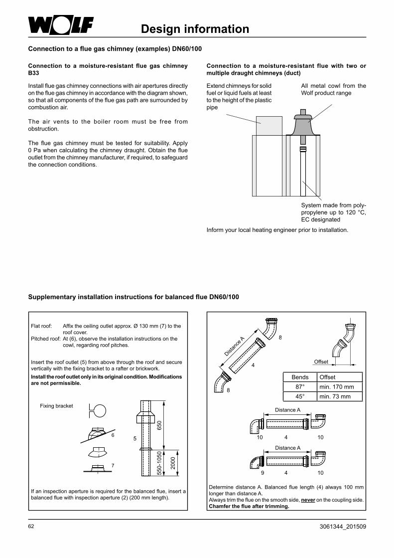
62 3061344_201509
Design information
Bends Offset87° min. 170 mm45° min. 73 mm
Connection to a moisture-resistant flue with two or multiple draught chimneys (duct)
Extend chimneys for solid fuel or liquid fuels at least to the height of the plastic pipe
All metal cowl from the Wolf product range
System made from poly-propylene up to 120 °C, EC designated
Inform your local heating engineer prior to installation.
Connection to a moisture-resistant flue gas chimney B33
Install flue gas chimney connections with air apertures directly on the flue gas chimney in accordance with the diagram shown, so that all components of the flue gas path are surrounded by combustion air.
The air vents to the boiler room must be free from obstruction.
The flue gas chimney must be tested for suitability. Apply 0 Pa when calculating the chimney draught. Obtain the flue outlet from the chimney manufacturer, if required, to safeguard the connection conditions.
Supplementary installation instructions for balanced flue DN60/100
Flat roof: Affix the ceiling outlet approx. Ø 130 mm (7) to the roof cover.
Pitched roof: At (6), observe the installation instructions on the cowl, regarding roof pitches.
If an inspection aperture is required for the balanced flue, insert a balanced flue with inspection aperture (2) (200 mm length).
Insert the roof outlet (5) from above through the roof and secure vertically with the fixing bracket to a rafter or brickwork.Install the roof outlet only in its original condition. Modifications are not permissible.
Determine distance A. Balanced flue length (4) always 100 mm longer than distance A.Always trim the flue on the smooth side, never on the coupling side. Chamfer the flue after trimming.
Distan
ce A
Offset
Distance A
Distance A
Connection to a flue gas chimney (examples) DN60/100
4
8
8
10
9
10
10
4
4
Fixing bracket
6
7
5
65
05
50
-10
50
20
00
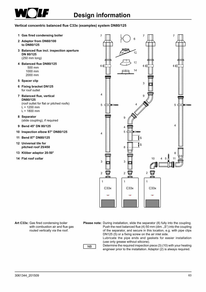
633061344_201509
Art C33x: Gas fired condensing boiler with combustion air and flue gas routed vertically via the roof.
Please note: During installation, slide the separator (8) fully into the coupling. Push the next balanced flue (4) 50 mm (dim. „S“) into the coupling of the separator, and secure in this location, e.g. with pipe clips DN125 (5) or a fixing screw on the air inlet side.
Lubricate the pipe ends and gaskets for easier installation (use only grease without silicone).
Determine the required inspection piece (3) (10) with your heating engineer prior to the installation. Adaptor (2) is always required.
NB
Design informationVertical concentric balanced flue C33x (examples) system DN80/125
22 2
33
8
8
44
4
9
9
3
5
5
10 4 5 11
S
S
6 6 6
4
5
4
7 7 7
111
12
13
6
14
1 Gas fired condensing boiler
2 Adaptor from DN60/100 to DN80/125
3 Balanced flue incl. inspection aperture DN 80/125 (250 mm long)
4 Balanced flue DN80/125 500 mm 1000 mm 2000 mm
5 Spacer clip
6 Fixing bracket DN125 for roof outlet
7 Balanced flue, vertical DN80/125 (roof outlet for flat or pitched roofs) L = 1200 mm L = 1800 mm
8 Separator (slide coupling), if required
9 Bend 45° DN 80/125
10 Inspection elbow 87° DN80/125
11 Bend 87° DN80/125
12 Universal tile for pitched roof 25/450
13 Klöber adaptor 20-50°
14 Flat roof collar
C33x C33x C33x

64 3061344_201509
Design informationHorizontal concentric balanced flue C13x, C83x and B33and flue on an external wall C53x (examples) DN 80/125
90 mm Ø opening in the chimney side. Install the flue airtight into the chimney side.
Install the horizontal flue with approx. 3° slope (6 cm/m) towards the boiler. Route the horizontal air supply with a 3° slope towards the outside – install the air inlet with wind protection; permissible wind pressure at the air inlet 90 Pa. The burner will not operate with higher wind pressure. Inside the duct downstream of the support bend (23), the flue can be routed in DN 80. A flexible flue DN 83 can be connected downstream of the support bend (23).
1621
22
23
24
25
26
4 5
4 5
4 16 16
2 2
15 16
220
>400
3
11 4 5
2
10
10
17
18
20
18
17
18
19
20
18
111
Horizontal balanced flue routing through a pitched roof
Flue on an external wall
(where required)
C13 x C53x B33
Dormer 1 Gas fired condensing boiler
2 Adaptor from DN60/100 to DN80/125
3 Balanced flue incl. inspection aperture DN80/125 (250 mm long)
4 Balanced flue DN80/125 500 mm 1000 mm 2000 mm
5 Spacer clip
10 Inspection elbow 87° DN80/125
11 Bend 87° DN80/125
15 Balanced flue horizontal, incl cowl
16 Rose
17 External wall panel 87° DN80/125 with smooth air pipe end
18 Balanced flue pipe, external wall DN80/125
19 LAir inlet piece, external wall DN80/125
20 conc. terminal end with clamping strap
21 Connection to a flue gas chimney B33 Length 250 mm with air apertures
22 Support rail
23 Support bend 87° DN80
24 Spacers
25 PP flue DN80
26 Duct cover with UV-stabilised terminal
28 Inspection tee
29 Air pipe Ø 125 mm
30 Air inlet pipe Ø 125 mm
16 16 4 55 2930 28
2
4 16
22
23
24
25
26
1
C83 x

653061344_201509
4
>20 >305
Design information
Inform your local heating engineer prior to installation.
C93x balanced flue in a duct DN 80
C93x balanced flue in a duct DN 80/125
B33 open flue in a duct DN 80
C93 x balanced flue system DN 80/185 horizontal and DN 80 vertical
16
22
11
4 5
4
2
26
10
4
8
1
C33x
Connection to a concentric balanced flue inside a duct (example) DN80/125, C33xConnection to the flue inside a duct, C93x
1 Gas fired condensing boiler
2 Adaptor from DN60/100 to DN80/125
4 Balanced flue DN80/125 500 mm 1000 mm 2000 mm
5 Spacer clip
8 Separator (slide coupling), if required
10 Inspection elbow 87° DN80/125
11 Support bend 87° DN80/125
16 Rose
22 Support rail
26 Duct cover with UV-stabilised terminal

66 3061344_201509
2
31
33 3432 25 161616
22
23
25
26
1
2
34 25 16
22
23
24
25
26
1
Design informationInstall the balanced flue distributor 80/80 mm eccentric (31) for separate air supply/flue gas routing acc. to (2) downstream of the connection adaptor DN 80/125 with a test connector.When connecting a balanced flue certified acc. to Building Regulations, observe the permit of the relevant body.Install the horizontal flue with approx. 3° slope (5 cm/m) towards the boiler. Route the horizontal air supply with a 3° slope towards the outside – install the air inlet with a cowl; permissible wind pressure at the air inlet 90 Pa. The burner will not operate with higher wind pressure.
Eccentric balanced flue
Maintain the following clearance between the internal duct wall and the flue: for circular ducts: 3 cm for rectangular ducts: 2 cm
Secondary ventilation
Secondary ventilation
1 Gas fired condensing boiler
2 Adaptor from DN 60/100 to DN 80/125
16 Rose
22 Support rail
23 Support bend 87° DN 80
24 Spacers
25 PP Flue DN80 500 mm 1000 mm 2000 mm
26 Duct cover with UV-stabilised terminal
31 Balanced flue distributor 80/80 mm
32 Air inlet pipe Ø 125 mm
33 Bend 90° DN80
34 Tee 87° with inspection aperture DN80
C53
C53
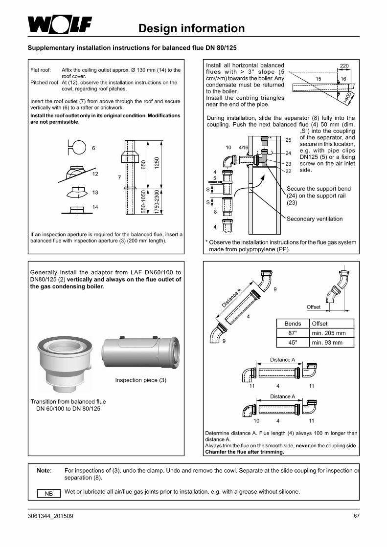
673061344_201509
Design informationSupplementary installation instructions for balanced flue DN 80/125
Flat roof: Affix the ceiling outlet approx. Ø 130 mm (14) to the roof cover.
Pitched roof: At (12), observe the installation instructions on the cowl, regarding roof pitches.
If an inspection aperture is required for the balanced flue, insert a balanced flue with inspection aperture (3) (200 mm length).
Insert the roof outlet (7) from above through the roof and secure vertically with (6) to a rafter or brickwork.Install the roof outlet only in its original condition. Modifications are not permissible.
Note: For inspections of (3), undo the clamp. Undo and remove the cowl. Separate at the slide coupling for inspection or separation (8).
Wet or lubricate all air/flue gas joints prior to installation, e.g. with a grease without silicone.NB
Transition from balanced flue DN 60/100 to DN 80/125
Inspection piece (3)
25
22
23
24
8
4
4
5
S
S
10 164/
Generally install the adaptor from LAF DN60/100 to DN80/125 (2) vertically and always on the flue outlet of the gas condensing boiler.
Determine distance A. Flue length (4) always 100 m longer than distance A.Always trim the flue on the smooth side, never on the coupling side. Chamfer the flue after trimming.
4
9
9
Distan
ce A
Offset
11
10
11
11
4
4
Distance A
Distance A
During installation, slide the separator (8) fully into the coupling. Push the next balanced flue (4) 50 mm (dim.
„S“) into the coupling of the separator, and secure in this location, e.g. with pipe clips DN125 (5) or a fixing screw on the air inlet side.
* Observe the installation instructions for the flue gas system made from polypropylene (PP).
Secure the support bend (24) on the support rail (23)
Secondary ventilation
*
Install all horizontal balanced f lues with > 3° s lope (5 cm//>m) towards the boiler. Any condensate must be returned to the boiler.Install the centring triangles near the end of the pipe.
15 16
220
>400
Bends Offset87° min. 205 mm45° min. 93 mm
12
13
6
14
7
65
05
50
-10
50
12
50
1750-2
300

68 3061344_201509
Underfloor heating system
Design information
Operation of the gas fired condensing centre with a DHW circulation line:
We recommend proper insulation of the pipework where the gas fired condensing centre is connected to a DHW circulation line. In addition, equip the DHW circulation line with a time switch. This is commonly started for DHW operation during times of demand. We recommend the following procedure for the optimum, energy-efficient adjustment of the time switch:
Never set the time switch permanently ON during times of demand, but ON and OFF in 15 minute intervals. The slight cooling down of the heated water inside the DHW circulation line will not result in any loss of convenience.
Your DHW circulation pump will then be adjusted so that energy consumption is minimised yet DHW convenience is maximised. This enables the DHW circulation pump ON-time to be reduced by 50 %.
When you operate a gas fired boiler together with an underfloor heating system, we recommend you size the available volume of the diaphragm expansion vessel 20 % greater than recommended by the relevant standard. A diaphragm expansion vessel which is too small will result in an ingress of oxygen into the heating system and therefore lead to corrosion damage.
NB
When using pipes which are impermeable to oxygen, the un-derfloor heating system can be directly connected to a heating system with a rated output of up to 13 kW, subject to system pressure drop.Generally install a thermostat for underfloor heating systems, to protect the pipes from overheating.
When connecting underfloor heating systems with a demand higher than approx. 13 kW, an additional three-way mixer plus an additional pump will be required.
Install a regulating valve in the return, which can reduce the excessive head of the additional pump, if required. Regulating valves must not be able to be adjusted
by the system user. Provide system separation by means of a heat
exchanger, when using pipes which are not imper-meable to oxygen. Inhibitors are not permissible.
If an additional heating circuit is operated in parallel to the underfloor heating system, match that circuit hydraulically to that of the underfloor heating system.
NB Fig.: Underfloor heating system

693061344_201509
Technical maintenanceand engineering details
Temperature/pressure drop
0°C 16325 Ω 15°C 7857 Ω 30°C 4028 Ω 60°C 1244 Ω
5°C 12697 Ω 20°C 6247 Ω 40°C 2662 Ω 70°C 876 Ω
10°C 9952 Ω 25°C 5000 Ω 50°C 1800 Ω 80°C 628 Ω
Category
Boiler CGB-11 CGB-(K)-20 CGB-(K)-24
Category I2H II2H3P II2H3P
Types of connection
1) Marking „x“ indicates that all flue pipe components are surrounded by combustion air.
Boiler Type 1) Operating mode To be connected to..Openflue
Balancedflue
moisture-resistantchimney
balanced flue chimney
balanced flue routing
acc. to BuildRegs cert. LAF
moisture-resistant flue
CGB-(K) B23, B33, C13x, C33x, C43x, C53, C53x, C83x, C93x
X X B33, C53, C83x C43x C13x2), C33x, C53x
C63x B23, C53x, C83x, C93x
Sensor resistances
Temperature [°C]
Res
ista
nce
[Ohm
]
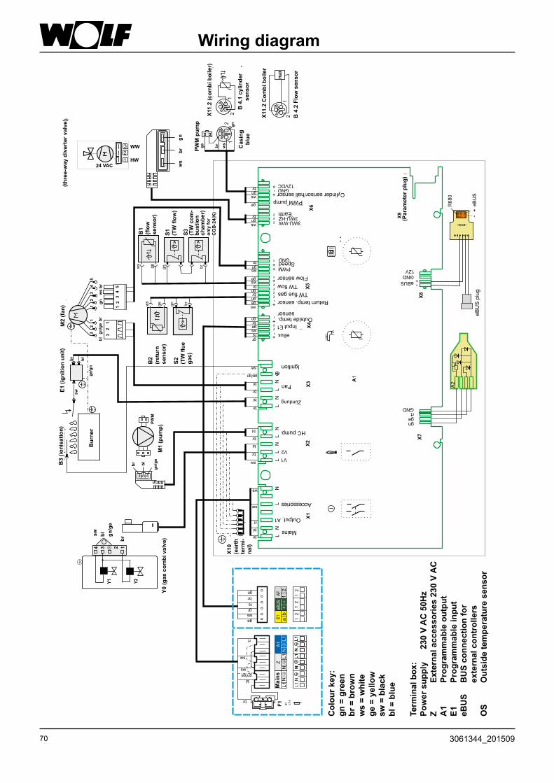
70 3061344_201509
21
HW
WW
(3-W
eg
eu
msch
alt
ven
til)
3
2
1
24 VAC
54
33
22
11
M2
(Ven
tila
tor)
gn
/ge
br
br
bl
ws
gn
M1
(Pu
mp
e)
21
12
E1
(Zü
nd
ein
he
it)
B3
(Io
nis
ati
on
)
bl
br
ge/g
n
sw
Bre
nn
er
Geh
äu
se
bla
u
12
Y0
(Ga
sk
om
biv
en
til)
Y2
Y1
X10
(Sch
utz
-
leit
er-
kle
mm
e)
br
PW
M
PW
MP
um
pe
bl
gn
/ge
34
52
1
32
1
LN
LN
LL
NL
NL
NL
N+
-~
+-
+-
~~
~~
~+-
++-
~~
~+
+-
Netz
AusgangA1
Zubehör
V1
V2
HK-Pumpe
Zündung
Ventilator
Ionisation
eBUS
eB
US
eB
US
-Ste
cke
r
gn
ge
rt
GND
GND
R6
80
12V
+
+
-
-
eBus
EingangE1
Außenfühler
Rücklauffühler
TW-Abgas
TW-Vorlauf
Vorlauffühler
PWM
DrehzahlGND
3WU-WW3WU-HZ
Masse
Speicherfühler/Hallsensor
GND
12VDC
PWMPumpe
gn
br
ws
B2
(Rü
ck
lau
f-
füh
ler)
S2
(TW
-Ab
ga
s)
>
X1
X2
X3
X6
X4
X7
X5
X9
(Pa
ra
me
ters
tec
ke
r)
X8
br
gn
ge
ws
X1
2
B4
.1S
pe
ich
erfü
hle
r
br
ws
ge
gn
br
ws
gn
br
gnws
gews
br
gnbr
gn
ge
ws
ge/gn
sw
bl
br
bl
br
bl
br
bl
br
sw
br
bl
sw
ws
rs
br
ws
gr
gn
ge
ws
ge
gn br
X11
.1(H
eiz
the
rm
e)
A2
A1
brb
l
sw
gn
/ge
1234
oo
oo
oo
MT
3,15
A
F1
br
bl
gn/ge
sw
ws
rt
gn
ws
gr
rs
br
ge
rt
B1
(Vo
rla
uf-
füh
ler)
S1
(TW
-
Vo
rla
uf)
>
ws
ge
gn
br
S3
(TW
-Bre
nn
-
ka
mm
er)
>
nu
rb
ei
CG
B-2
4(K
)
21
12
B4
.2D
urc
hfl
uß
se
ns
or
X11
.2(K
om
bit
he
rm
e)
Hall
AF
E1
eB
US
+-
12
ab
Netz
ZA
1
N
N
NL
1L
1L
1
12
12
12
L1
NL
1N
L1
NL
1N
L1
N
Wiring diagram
Term
inal
box
: Po
wer
sup
ply
23
0 V
AC
50H
zZ
Exte
rnal
acc
esso
ries
230
V A
CA
1 Pr
ogra
mm
able
out
put
E1
Prog
ram
mab
le in
put
eBU
S B
US
conn
ectio
n fo
r
exte
rnal
con
trol
lers
OS
Out
side
tem
pera
ture
sen
sor
Mains
Output
Accessories
HC pump
Ignition
Fan
InputOutside temp.
sensor
Return temp. sensorTW flue gas
TW flowFlow sensor
Speed
Earth
PWM pumpCylinder sensor/hall sensor
eBU
S p
lug
(Par
amet
er p
lug)
X11.
2 (c
ombi
boi
ler)
Cas
ing
blue
B 4
.1 c
ylin
der
sens
or
X11.
2 C
ombi
boi
ler
B 4
.2 F
low
sen
sor
PWM
pum
p
(thre
e-w
ay d
iver
ter v
alve
)
B1
(flow
se
nsor
)
S1
(TW
flow
)
S3 (TW
com
-bu
stio
n ch
ambe
r)on
ly fo
r C
GB
-24(
K)
M2
(fan)
E1 (i
gniti
on u
nit)
B2
(r
etur
n se
nsor
)
S2
(TW
flue
ga
s)
B3
(ioni
satio
n)
Bur
ner
M1
(pum
p)Y0
(gas
com
bi v
alve
)
Mai
ns
Col
our k
ey:
gn =
gre
enbr
= b
row
nw
s =
whi
tege
= y
ello
wsw
= b
lack
bl =
blu
e
X10
(ear
th
term
i-na
l)

713061344_201509
Specification
1) Heating mode/DHW mode2) Relative to a cold water temperature of 10 °C
Type CGB-11 CGB-20 CGB-K-20 CGB-24 CGB-K-24Nominal output at 80/60 °CNominal output at 50/30 °CRated thermal loadLowest output (modulating) at 80/60Lowest output (modulating) at 50/30Lowest thermal load (modulating)
kWkWkWkWkWkW
10,0/14,6 1)
10,910,3/15,0 1)
3,23,63,3
19,0/22,9 1)
20,519,5/23,5 1)
5,66,15,7
19,0/22,9 1)
20,5/-19,5/23,5 1)
5,66,15,7
23,1/27,61)
24,8/-23,8/28,51)
7,17,87,3
23,1/27,61)
24,8/-23,8/281)
7,17,87,3
SEDBUKNaturalgasLPG
bandband
B-
BB
BB
BB
BB
SAP 2009 annual efficiencyNaturalgasLPG
%%
88.9-
88.989.9
88.889.8
88.889.7
88.789. 7
Outside diameter heating flowOutside diameter heating returnDHW connectionCold water inletGas connectionAir/flue gas connection
mmmm
GGR
mm
20(G¾)20(G¾)
¾¾½
60/100
20 (G¾)20 (G¾)
¾¾ ½
60/100
20 (G¾)20 (G¾)
¾¾½
60/100
20 (G¾)20 (G¾)
¾¾½
60/100
20 (G¾)20 (G¾)
¾¾½
60/100Gas connection value: Natural gas H (Hi = 9,5 kWh/m³=34,2MJ/m³) LPG (Hi = 12,8 kWh/kg=46,1MJ/kg)Gas supply pressure: Natural gas LPG
m3/hkg/h
mbarmbar
1,08/1,58 1)
-
20-
2,05/2,47 1)
1,52/1,84 1)
2050
2,05/2,47 1)
1,52/1,84 1)
2050
2,50/3,00 1))1,83/2,231)
2050
2,50/3,001))1,86/2,231)
2050
Flow temperature, factory settingFlow temperature, factory settingMax. system pressureHeating water heat exchanger water contentDHW throughputMinimum flow pressure/Min. flow press. to EN625Spec. water flow rate „D“ at ∆T = 30 KMax. design pressureDHW temperature range 2)
DHW heat exchanger corrosion protection
°C°C
barLtr.
l/minbar
l/minbar°C
75903,01,3------
75903,01,3------
75903,01,3
2,0-6,50,2/1,0
9,410
40 - 60stainless steel
75903,01,3------
75903,01,3
2,0-8,00,2/1,0
13,010
40-60stainless steel
Expansion vessel: Total capacity Inlet pressure
Ltr.bar
120,75
120,75
120,75
120,75
120,75
Permissible sensor temperaturesFlue gas mass flow rate QmaxFlue gas mass flow rate QminFlue gas temperature 80/60 - 50/30 QmaxFlue gas temperature 80/60 - 50/30 QminAvailable gas fan draught QmaxAvailable gas fan draught QminFlue gas values to DVGW G 635
°Cg/sg/s°C°CPaPa
954,7/6,8 1)
1,4575-4545-26
9012G52
958,9/10,7 1)
2,6275-4536-27
9012G52
958,9/10,7 1)
2,6275-4536-27
9012G52
9510,8/13,0 1)
2,785-4543-41
9012G52
9510,8/13,0 1)
2,785-4543-41
9012G52
Fitted fuse (medium slow)Fitted fuse (medium slow)Power consumption with modulating pump class A pumpPower consumption with 3-stage-pump
V~/HzA
WW
230/503,1590110
230/503,1590110
230/503,1590110
230/503,1590110
230/503,15105110
Protection IPX4D IPX4D IPX4D IPX4D IPX4DTotal weight kg 42 42 45 42 45Condensate volume at 50/30°CCondensate ph value
litres./h approx. 1,2approx. 4,0
approx. 2,0approx. 4,0
approx. 2,0approx. 4,0
approx. 2,4approx. 4,0
approx. 2,4approx. 4,0
CE designation CE 0085BN0380
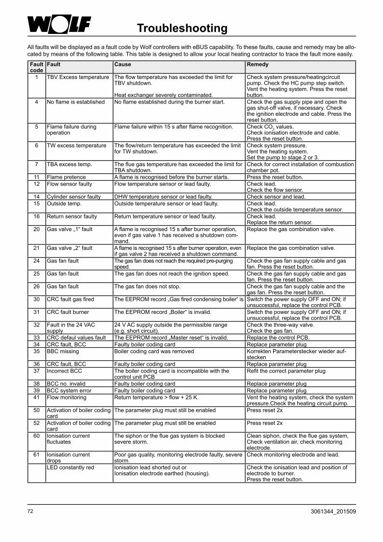
72 3061344_201509
TroubleshootingAll faults will be displayed as a fault code by Wolf controllers with eBUS capability. To these faults, cause and remedy may be allo-cated by means of the following table. This table is designed to allow your local heating contractor to trace the fault more easily.
Fault code
Fault Cause Remedy
1 TBV Excess temperature The flow temperature has exceeded the limit for TBV shutdown.
Heat exchanger severely contaminated.
Check system pressure/heatingcircuit pump. Check the HC pump step switch. Vent the heating system. Press the reset button.
4 No flame is established No flame established during the burner start. Check the gas supply pipe and open the gas shut-off valve, if necessary. Check the ignition electrode and cable. Press the reset button.
5 Flame failure during operation
Flame failure within 15 s after flame recognition. Check CO2 values. Check ionisation electrode and cable.Press the reset button.
6 TW excess temperature The flow/return temperature has exceeded the limit for TW shutdown.
Check system pressure.Vent the heating system.Set the pump to stage 2 or 3.
7 TBA excess temp. The flue gas temperature has exceeded the limit for TBA shutdown.
Check for correct installation of combustion chamber pot.
11 Flame pretence A flame is recognised before the burner starts. Press the reset button.12 Flow sensor faulty Flow temperature sensor or lead faulty. Check lead.
Check the flow sensor.14 Cylinder sensor faulty DHW temperature sensor or lead faulty. Check sensor and lead.15 Outside temp. Outside temperature sensor or lead faulty. Check lead.
Check the outside temperature sensor.16 Return sensor faulty Return temperature sensor or lead faulty. Check lead.
Replace the return sensor.20 Gas valve „1“ fault A flame is recognised 15 s after burner operation,
even if gas valve 1 has received a shutdown com-mand.
Replace the gas combination valve.
21 Gas valve „2“ fault A flame is recognised 15 s after burner operation, even if gas valve 2 has received a shutdown command.
Replace the gas combination valve.
24 Gas fan fault The gas fan does not reach the required pre-purging speed.
Check the gas fan supply cable and gas fan. Press the reset button.
25 Gas fan fault The gas fan does not reach the ignition speed. Check the gas fan supply cable and gas fan. Press the reset button.
26 Gas fan fault The gas fan does not stop. Check the gas fan supply cable and the gas fan. Press the reset button.
30 CRC fault gas fired The EEPROM record „Gas fired condensing boiler“ is Switch the power supply OFF and ON; if unsuccessful, replace the control PCB.
31 CRC fault burner The EEPROM record „Boiler“ is invalid. Switch the power supply OFF and ON; if unsuccessful, replace the control PCB.
32 Fault in the 24 VACsupply
24 V AC supply outside the permissible range(e.g. short circuit).
Check the three-way valve.Check the gas fan.
33 CRC defaul values fault The EEPROM record „Master reset“ is invalid. Replace the control PCB.34 CRC fault, BCC Faulty boiler coding card Replace parameter plug35 BBC missing Boiler coding card was removed Korrekten Parameterstecker wieder auf-
stecken36 CRC fault, BCC Faulty boiler coding card Replace parameter plug37 Incorrect BCC The boiler coding card is incompatible with the
control unit PCBRefit the correct parameter plug
38 BCC no. invalid Faulty boiler coding card Replace parameter plug39 BCC system error Faulty boiler coding card Replace parameter plug41 Flow monitoring Return temperature > flow + 25 K. Vent the heating system, check the system
pressure.Check the heating circuit pump.50 Activation of boiler coding
cardThe parameter plug must still be enabled Press reset 2x
52 Activation of boiler coding card
The parameter plug must still be enabled Press reset 2x
60 Ionisation current fluctuates
The siphon or the flue gas system is blockedsevere storm.
Clean siphon, check the flue gas system, Check ventilation air, check monitoring electrode.
61 Ionisation currentdrops
Poor gas quality, monitoring electrode faulty, severe storm.
Check monitoring electrode and lead.
LED constantly red Ionisation lead shorted out orIonisation electrode earthed (housing).
Check the ionisation lead and position of electrode to burner.Press the reset button.
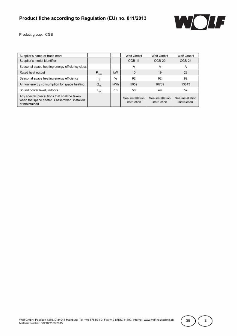
733061344_201509
Product fiche according to Regulation (EU) no. 811/2013
Product group: CGB
Supplier’s name or trade mark Wolf GmbH Wolf GmbH Wolf GmbHSupplier’s model identifier CGB-11 CGB-20 CGB-24
Seasonal space heating energy efficiency class A A A
Rated heat output Prated kW 10 19 23
Seasonal space heating energy efficiency ηs % 92 92 92
Annual energy consumption for space heating QHE kWh 5652 10739 13043
Sound power level, indoors LWA dB 50 49 52
Any specific precautions that shall be taken when the space heater is assembled, installed or maintained
See installation instruction
See installation instruction
See installation instruction
Wolf GmbH, Postfach 1380, D-84048 Mainburg, Tel. +49-8751/74-0, Fax +49-8751/741600, Internet: www.wolf-heiztechnik.deMaterial number: 3021052 03/2015
GB IE

74 3061344_201509
Product fiche according to Regulation (EU) no. 811/2013
Product group: CGB-K
Supplier’s name or trade mark Wolf GmbH Wolf GmbHName CGB-K-20 CGB-K-24
Load profile XL XL
Seasonal space heating energy efficiency class A A
Water heating energy efficiency class A A
Rated heat output Prated kW 19 23
Annual energy consumption for space heating QHE kWh 10739 13043
Annual fuel consumption for water heating AFC GJ 18 18
Seasonal space heating energy efficiency ηs % 92 92
Seasonal water heating energy efficiency ηwh % 82 82
Sound power level, indoors LWA dB 49 52
Any specific precautions that shall be taken when the space heater is assembled, installed or maintained
See installation instruction
See installation instruction
Wolf GmbH, Postfach 1380, D-84048 Mainburg, Tel. +49-8751/74-0, Fax +49-8751/741600, Internet: www.wolf-heiztechnik.deMaterial number: 3021099 03/2015
GB IE

753061344_201509
Technical parameters according to EU regulation no. 813/2013
Type CGB-11 CGB-20 CGB-K-20 CGB-24 CGB-K-24Condensing boiler [yes/no] yes yes yes yes yesLow temperature boiler (**) [yes/no] no no no no noB11 boiler [yes/no] no no no no noCogeneration space heater [yes/no] no no no no noIf yes, equipped with a supple-mentary heater
[yes/no] - - - - -
Combination heater [yes/no] no no yes no yesItem Symbol UnitRated heat output Prated kW 10 19 19 23 23Useful heat output at rated heat output and high-temperature regime (*)
P4 kW 10,0 19,0 19,0 23,1 23,1
Useful heat output at 30% of rated heat output and low-tem-perature regime (**)
P1 kW 3,0 5,7 5,7 6,9 6,9
Auxiliary electricity consumption at full load
elmax kW 0,015 0,022 0,022 0,028 0,028
Auxiliary electricity consumption at part load
elmin kW 0,010 0,012 0,012 0,015 0,015
Auxiliary electricity consumption in standby mode
PSB kW 0,005 0,005 0,005 0,005 0,005
Seasonal space heating energy efficiency
ns % 92 92 92 92 92
Useful efficiency at rated heat output and high-temperature regime (*)
n4 % 87,9 88,0 88,0 87,8 87,8
Useful efficiency at 30% of rated heat output and low-temperature regime (**)
n1 % 97,3 96,7 96,7 96,7 96,7
Standby heat loss Pstby kW 0,049 0,049 0,049 0,048 0,048Ignition burner power consump-tion
Ping kW 0,000 0,000 0,000 0,000 0,000
Emissions of nitrogen oxides NOx mg/kWh 12 19 19 19 19Declared load profile (M, L,
XL, XXL)- - - XL - XL
Daily electricity consumption Qelec kWh - - 0,162 - 0,171Water heating energy efficiency nwh % - - 82 - 82Daily fuel consumption Qfuel kWh - - 23,956 - 23,844Contact details Wolf GmbH, Industriestraße 1, D-84048 Mainburg
(*) High-temperature regime means 60°C return temperature at heater inlet and 80°C feed temperature at heater outlet.(**) Low temperature means for condensing boilers 30°C, for low-temperature boilers 37°C and for other heaters 50°C return temperature (at heater inlet).
Product fiche according to Regulation (EU) no. 811/2013
Product group: CGB-K
Supplier’s name or trade mark Wolf GmbH Wolf GmbHName CGB-K-20 CGB-K-24
Load profile XL XL
Seasonal space heating energy efficiency class A A
Water heating energy efficiency class A A
Rated heat output Prated kW 19 23
Annual energy consumption for space heating QHE kWh 10739 13043
Annual fuel consumption for water heating AFC GJ 18 18
Seasonal space heating energy efficiency ηs % 92 92
Seasonal water heating energy efficiency ηwh % 82 82
Sound power level, indoors LWA dB 49 52
Any specific precautions that shall be taken when the space heater is assembled, installed or maintained
See installation instruction
See installation instruction
Wolf GmbH, Postfach 1380, D-84048 Mainburg, Tel. +49-8751/74-0, Fax +49-8751/741600, Internet: www.wolf-heiztechnik.deMaterial number: 3021099 03/2015
GB IE
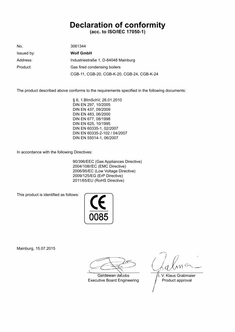
Gerdewan JacobsExecutive Board Engineering
Mainburg, 15.07.2015
Declaration of conformity(acc. to ISO/IEC 17050-1)
No. 3061344
Issued by: Wolf GmbH
Address: Industriestraße 1, D-84048 Mainburg
Product: Gas fired condensing boilers
CGB-11, CGB-20, CGB-K-20, CGB-24, CGB-K-24
The product described above conforms to the requirements specified in the following documents:
§ 6, 1.BImSchV, 26.01.2010DIN EN 297, 10/2005DIN EN 437, 09/2009DIN EN 483, 06/2000DIN EN 677, 08/1998DIN EN 625, 10/1995DIN EN 60335-1, 02/2007DIN EN 60335-2-102 / 04/2007DIN EN 55014-1, 06/2007
In accordance with the following Directives:
90/396/EEC (Gas Appliances Directive)2004/108//EC (EMC Directive)2006/95/EC (Low Voltage Directive)2009/125/EG (ErP Directive) 2011/65/EU (RoHS Directive)
This product is identified as follows:
0085
i. V. Klaus GrabmaierProduct approval