installation instructions - valor title pdf manuals/bilingual... · section of mantel, wall finish...
TRANSCRIPT

TM
Note: This kit must be installed or serviced by a qualified installer, service agency or gas supplier. These instructions are to be used in conjunction with the main installation instructions for the above listed model.
WARNING: If the information in these instructions is not followed exactly, a fire or explosion may result causing property damage, personal injury or loss of life.
FOR ENGINE CONFIGURATIONS AND VENTING,REFER TO MAIN INSTALLATION BOOKLET SUPPLIED WITH THE ENGINE.
FOR MANTEL, FRONT, FRET AND DOORS INSTALLATIONS,REFER TO INSTALLATION BOOKLET SUPPLIED WITH EACH KIT.
GENERALThis kit consists of a set of black sheet metal panels used to extend the perimeter size of the engine to accommodate StoneFire mantels, with the addition of an inner cast iron frame and selection of door options.
Kit components Installation diagram (See price list for choice of Fronts, Frets and Door Kits.)
SFMK01STONEFIRE INNER FRAME KIT
INSTALLATION INSTRUCTIONSCSA approved for use only with
Valor Model 530 Heater and a StoneFire Mantel
4001105/03

�
This kit is designed to use with the Stonefire mantels.
SMTR StoneFire Traditional Mantel
SMCL StoneFire Classic Mantel
SMCO StoneFire Contemporary Mantel

3
Note: These instructions are in addition to installation instructions supplied with Valor 530 firebox unit. Any combustible framing construction must be clear of standoffs.
A non-combustible hearth is not necessary in front of this appliance.The 530 fireplace is approved to install directly on wood sub-flooring.Any combustible framing construction must be clear of standoffs.
•••
Sheet metal frame dimensions
Section of mantel, wall finish & framing kit
Framing Diagram
The wall board opening MUST be a minimum of 27-1/2” wide x 36-1/4” high
Detail of section of mantel top, wall finish & framing kit (side view)Wall finish
Mantel top*
Top cover*
ShieldDuct
530 engine
Header
Top cover*
Header
FRAMING
*Mantel top hooks onthe top cover lip; top cover is fixed on each side to wood frame

4
FRAMING (cont.)

5
HEARTH INSTALLATION

6
KIT ASSEMBLYLocate leg brackets to sides of engine and secure with 4 #8 screws; locate and secure rear support.
Secure duct to leg framing using 2 screw holes lo-cated through rear of leg.
Position shield on top of duct and secure with 2 #8 screws. Note: Shield can be placed in two positions depen-dant of what Stonefire mantel is being installed.
1.
2.
3.
Locate and secure standoffs to rear corners of engine.
Place the insulation pad on top of the engine, cutting around the pipe if installing a top vent.
Place engine into cavity and secure to framing.
Rest top cover onto legs and secure to framing.
4.
5.
6.
7.

�
Designed and Manufactured for/byMILES INDUSTRIES LTD.
190 - 2255 Dollarton Hwy., North Vancouver, BC, CANADA V7H 3B1Tel. 604-984-3496 Fax 604-984-0246
www.milesfireplaces.com© 2006, Miles Industries Ltd. All rights reserved.
1 LH Standoff Bracket 40010��� RH Standoff Bracket 40010�33 Insulation Pad(s) 620B9874 Back Support 40008�55 LH Leg 4000818AZ6 RH Leg 4000819AZ� Shield 4000830AZ8 Duct Panel 400081�AZ9 Top Cover 4000816AZ
REPLACEMENT PARTS
8
MC
Note: Ce kit doit être installé et entretenu par un installateur qualifié, une agence de service certifiée ou un fournisseur de gaz. Ces instructions doivent être utilisées conjointement avec les instructions d’installation du foyer Valor modèle 530.
MISE EN GARDE: Si les instructions fournies dans le présent manuel ne sont pas suivies à la lettre, un feu ou une explosion pourraient résulter et causer des dommages matériels, des blessures ou la mort.
POUR LA CONFIGURATION DU FOYER ET DE L’ÉVACUATION,RÉFÉREZ-VOUS AU MANUEL D’INSTALLATION FOURNI AVEC LE FOYER.
POUR L’INSTALLATION DU MANTEAU DE CHEMINÉE, DE LA DEVANTURE, DE LA BASE CHANTOURNÉE, ET DES PORTES, RÉFÉREZ-VOUS AU MANUEL D’INSTALLATION FOURNI
AVEC CES KITS.
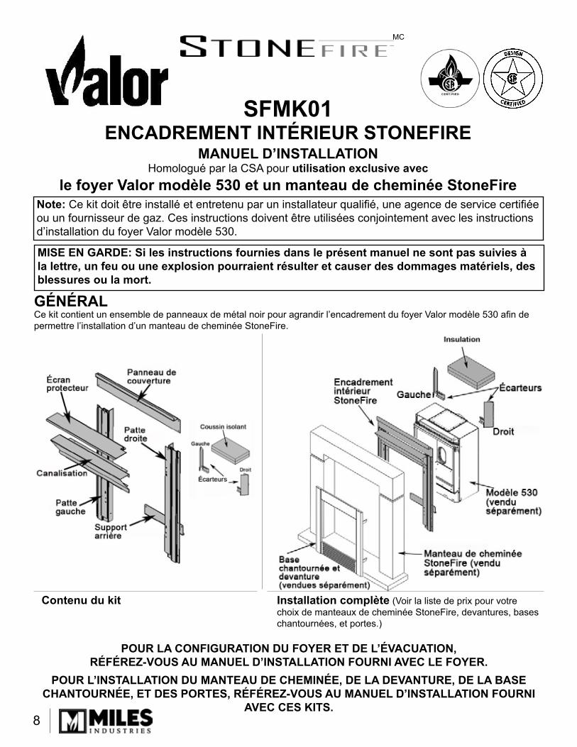
GÉNÉRALCe kit contient un ensemble de panneaux de métal noir pour agrandir l’encadrement du foyer Valor modèle 530 afin de permettre l’installation d’un manteau de cheminée StoneFire.
Contenu du kit Installation complète (Voir la liste de prix pour votre choix de manteaux de cheminée StoneFire, devantures, bases chantournées, et portes.)
SFMK01ENCADREMENT INTÉRIEUR STONEFIRE
MANUEL D’INSTALLATIONHomologué par la CSA pour utilisation exclusive avec
le foyer Valor modèle 530 et un manteau de cheminée StoneFire

9
Ce kit d’encadrement est conçu pour être utilisé avec les manteaux de cheminée Stonefire.
SMTR Manteau de cheminéeStoneFire Traditionel
SMCL Manteau de cheminéeStoneFire Classique
SMCO Manteau de cheminéeStoneFire Contemporain

10
Note: Ces instructions sont en plus des instructions fournies avec le foyer Valor 530.
Une base de foyer non-combustible n’est pas nécessaire devant cet appareilLe foyer 530 est homologué pour installation directement sur un sous-plancher de bois.Tout encastrement doit être construit à distance des écarteurs.
•••
Dimensions de l’encadrement
Coupe transversale du manteau, de la finition du mur et de l’encadrement
Schéma d’encastrement
Détail de coupe du linteau, de la finition du mur et de l’encadrement (vue de côté)Finition
du mur
Linteau*
Panneau decouverture*
Écranprotecteur
Canalisation
Moteur 530
Poutre
Panneau de couverture*
Poutre
ENCASTREMENT
*Le linteau s’accroche au rebord supérieur du panneau de couverture; le panneau de couverture est fixé de chaque côté à l’encastrement
L’ouverture pour le panneau du mur DOIT être d’un minimum de 70 cm (27-1/2”) de large sur 92 cm (36-1/4”) de haut.
93 cm (36-1/2”)
du dessous de la
poutre
(permettre plus d’espace pour les coudes pour évacuation arrière)
29 cm (11-1/2”) minimum 67 cm (26-1/4”)
66 cm (26”)
70 cm (27-1/2”)
92 cm(36-1/4”)
82 cm(32-1/4”)

11
ENCASTREMENT (suite)
1�
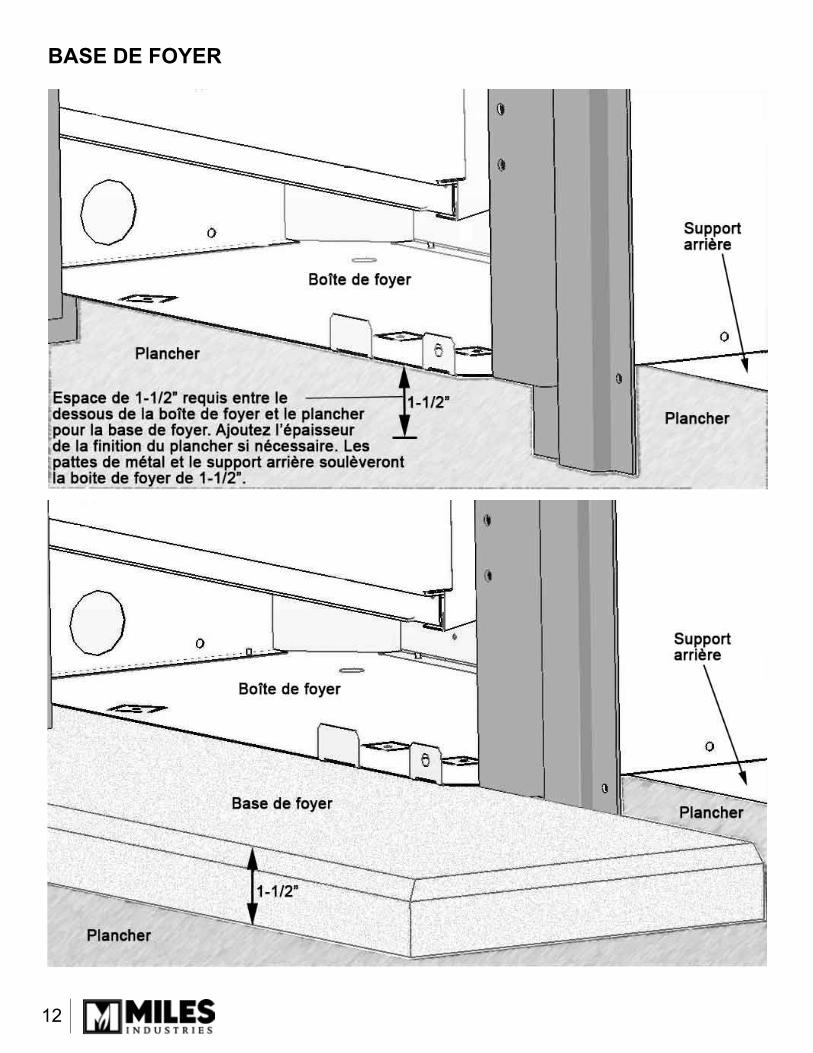
BASE DE FOYER

13
ASSEMBLAGE DE L’ENCADREMENTPlacez les pattes de métal de chaque côté du foyer et fixez-les avec 4 vis no. 8; placez et fixez le sup-port arrière au foyer.
Fixez la canalisation aux pattes de métal par les deux trous de vis situés à l’arrière des pattes.
Placez l’écran protecteur sur la canalisation et fixez-la avec 2 vis no. 8. Note : L’écran protecteur peut être positionné de deux façons selon le manteau Stonefire installé.
1.
2.
3.
Placez et fixez les écarteurs aux coins arrières du foyer.
Placez le coussin isolant sur le dessus de la boite de foyer. Coupez l’isolant pour permettre le passage du conduit d’évacuation lorsque l’installation requiert une évacuation sur le dessus.
Placez le foyer dans l’âtre et fixez-le à l’encastrement.
Placez le panneau de couverture sur les pattes et fixez-le à l’encastrement.
4.
5.
6.
7.

14
Conçu et fabriqué pour/parMILES INDUSTRIES LTD.
190 - 2255 Dollarton Hwy., North Vancouver, C.-B., CANADA V7H 3B1Tél. : 604-984-3496 Télec. : 604-984-0246
www.milesfireplaces.com© 2006, Miles Industries Ltd. Tous droits réservés.
1 Écarteur gauche 40010��� Écarteur droit 40010�33 Coussin isolant 620B9874 Support arrière 40008�55 Patte gauche 4000818AZ6 Patte droite 4000819AZ� Écran protecteur 4000830AZ8 Canalisation 400081�AZ9 Panneau de couverture 4000816AZ
PIÈCES DE REMPLACEMENT