installation instructions rf-identification system with ... · pdf fileinstallation...
TRANSCRIPT
Installation instructions RF-identification system
with integrated AS-i slaveDTSLF
8026
2952
/ 00
04
/ 20
17
UK

2
Content1 Preliminary note ���������������������������������������������������������������������������������������������������4
1�1 Symbols used �����������������������������������������������������������������������������������������������42 Safety instructions �����������������������������������������������������������������������������������������������4
2�1 General ���������������������������������������������������������������������������������������������������������42�2 Radio equipment ������������������������������������������������������������������������������������������52�3 Interference of electronic and medical devices ��������������������������������������������5
3 Functions and features ����������������������������������������������������������������������������������������54 Function ���������������������������������������������������������������������������������������������������������������5
4�1 Operating principle ���������������������������������������������������������������������������������������54�2 Type overview �����������������������������������������������������������������������������������������������6
5 Installation������������������������������������������������������������������������������������������������������������75�1 General installation instructions ��������������������������������������������������������������������75�2 Notes on ID tag mounting �����������������������������������������������������������������������������75�3 DTA10x ���������������������������������������������������������������������������������������������������������8
5�3�1 Fixing ����������������������������������������������������������������������������������������������������85�3�2 Mounting distances ������������������������������������������������������������������������������85�3�3 Positioning of the ID tags ����������������������������������������������������������������������95�3�4 Orientation of the ID tags ����������������������������������������������������������������������95�3�5 Read/write distances �������������������������������������������������������������������������10
5�4 DTA20x �������������������������������������������������������������������������������������������������������105�4�1 Mechanical design ������������������������������������������������������������������������������105�4�2 Alignment of the sensing face ������������������������������������������������������������� 115�4�3 Fixing �������������������������������������������������������������������������������������������������� 115�4�4 Mounting distances ����������������������������������������������������������������������������125�4�5 Positioning of the ID tags ��������������������������������������������������������������������125�4�6 Orientation of the ID tags ��������������������������������������������������������������������135�4�7 Read/write distances �������������������������������������������������������������������������13
5�5 DTA30x �������������������������������������������������������������������������������������������������������145�5�1 Fixing ��������������������������������������������������������������������������������������������������145�5�2 Mounting distances ����������������������������������������������������������������������������145�5�3 Positioning of the ID tags ��������������������������������������������������������������������155�5�4 Orientation of the ID tags ��������������������������������������������������������������������155�5�5 Read/write distances �������������������������������������������������������������������������155�5�6 Rotating plug insert �����������������������������������������������������������������������������16

3
UK
6 Electrical connection ������������������������������������������������������������������������������������������176�1 Wiring ���������������������������������������������������������������������������������������������������������176�2 Minimum distance between AS-i cable and housing ����������������������������������17
6�2�1 DTA10x �����������������������������������������������������������������������������������������������176�2�2 DTA20x �����������������������������������������������������������������������������������������������186�2�3 DTA30x �����������������������������������������������������������������������������������������������18
6�3 cULus ���������������������������������������������������������������������������������������������������������197 Indicators �����������������������������������������������������������������������������������������������������������19
7�1 Read operation (basic setting) ��������������������������������������������������������������������197�2 Write operation (only DTA100, DTA200, DTA300) �������������������������������������20
8 Operation �����������������������������������������������������������������������������������������������������������218�1 Basic settings in the AS-i network ��������������������������������������������������������������218�2 Addressing ��������������������������������������������������������������������������������������������������218�3 Analogue value representation �������������������������������������������������������������������218�4 Assignment of the data bits ������������������������������������������������������������������������218�5 Code value representation using the data bits D16���D1 ����������������������������228�6 Additional functions to the AS-i profile 7�4 ��������������������������������������������������22
9 Dimensions ��������������������������������������������������������������������������������������������������������239�1 DTA10x �������������������������������������������������������������������������������������������������������239�2 DTA20x �������������������������������������������������������������������������������������������������������239�3 DTA30x �������������������������������������������������������������������������������������������������������24
10 Technical data ��������������������������������������������������������������������������������������������������2411 Maintenance, repair and disposal ��������������������������������������������������������������������2412 Approvals/standards ����������������������������������������������������������������������������������������24
12�1 Radio approvals ����������������������������������������������������������������������������������������2412�1�1 Overview �������������������������������������������������������������������������������������������2412�1�2 Europe ����������������������������������������������������������������������������������������������2412�1�3 USA ��������������������������������������������������������������������������������������������������2512�1�4 Canada ���������������������������������������������������������������������������������������������2512�1�5 Taiwan ����������������������������������������������������������������������������������������������2512�1�6 Australia ��������������������������������������������������������������������������������������������2612�1�7 Singapore �����������������������������������������������������������������������������������������2612�1�8 EC declaration of conformity ������������������������������������������������������������26

4
1 Preliminary noteThis document applies to all DTSLF type units�It is part of the device and contains information about the correct handling of the product�This document is intended for specialists� These specialists are people who are qualified by their training and their experience to see risks and to avoid possible hazards that may be caused during operation or maintenance of the device�Read this document before use to familiarise yourself with operating conditions, installation and operation� Keep this document during the entire duration of use of the device�
1.1 Symbols used► Instruction→ Cross-reference
Important note Non-compliance can result in malfunctions or interference�Information Supplementary note
2 Safety instructions2.1 GeneralObserve the operating instructions� Non-observance of the instructions, operation which is not in accordance with use as prescribed below, wrong installation or handling can affect the safety of people and machinery�The installation and connection must comply with the applicable national and international standards� Responsibility lies with the person installing the unit�The unit must only be installed, connected and put into operation by a qualified electrician as the safe function of the unit and machinery is only guaranteed when installation is correctly carried out�Disconnect the unit externally before handling it�In case of malfunction of the device or uncertainties please contact the manufacturer� Tampering with the unit can seriously affect the safety of operators and machinery� This is not permitted and leads to an exclusion of liability and warranty�

5
UK
2.2 Radio equipmentIn general, radio equipment must not be used in the vicinity of petrol stations, fuel depots, chemical plants or blasting operations�
► Do not transport and store any flammable gases, liquids or explosive substances near the unit�
2.3 Interference of electronic and medical devicesOperation can affect the function of electronic devices that are not correctly shielded�
► Disconnect the device in the vicinity of medical equipment� ► Contact the manufacturer of the corresponding device in case of any interference�
3 Functions and featuresThe DTSLF RF identification system enables non-contact reading and/or writing of RFID transponders (ID tags) conforming to the system� The data is converted into digitally coded values and provided to the AS-i control level (AS-i master, controller or host)�Application examples:● Material flow control in production lines● Warehouse management by the automatic detection of stored products● Tank management, order picking or product tracking
4 Function4.1 Operating principleThe ID tags are operated passively, i�e� without battery� The energy required for operation is supplied by the read/write head� The physical principle of the energy transfer is based on inductive coupling� The integrated antenna coil in the read/write head generates a magnetic field which partly penetrates the antenna coil of the ID tag� A voltage is generated by induction that supplies the data carrier with energy�

6
�������
���������������������
������������������������
����
��� ������
����
��������������� ������
�����������������������������
function (example read/write head DTA100 and ID tag E80301)
4.2 Type overview
DTA10x DTA20x DTA30x
Art� no� Function Type designation H x V x D [mm] Max� transmission power:
DTA100 Read/write head DTSLF AARWASUS0155 x 24 x 41 200 mW
DTA101 Read head DTSLF AAROASUS01

7
UK
Art� no� Function Type designation H x V x D [mm] Max� transmission power:
DTA200 Read/write head DTSLF MCRWASUS0140 x 40 x 54 200 mW
DTA201 Read head DTSLF MCROASUS01DTA300 Read/write head DTSLF DCRWASUS01
92 X 80 X 40 200 mWDTA301 Read head DTSLF DCROASUS01
5 Installation5.1 General installation instructions
When mounting several read/write heads adhere to the minimum distances between the systems�Flush mounting of a read/write head in metal reduces the read/write distance� The immediate vicinity of powerful HF emission sources such as welding transformers or converters can affect operation of the read/write heads�
Information on the available mounting accessories is available on our website at: www�ifm�com
5.2 Notes on ID tag mounting
If the ID tags are mounted in/on metal, the read/write distance is reduced�
For positioning the ID tags the read/write heads are marked with an an-tenna symbol on the active face� It designates the middle of the integrated antenna coil and has to correspond with the middle of the ID tag�The orientation of the read/write head antenna axis must correspond with the axis of the ID tag coil�You can find out about the best way to position the available ID tags and on mounting in metal on our website at: www�ifm�com

8
5.3 DTA10x5.3.1 Fixing
► The device is fixed via either 2 M4 screws and nuts or via an angle bracket�
mounting example E20898 mounting example E20901
5.3.2 Mounting distances
� �
�
Operating mode Distance side (A) Distance front (B)Reading only ≥200mm ≥200mmFor reading and writing ≥400mm ≥400mm

9
UK
5.3.3 Positioning of the ID tags
������ ������ ������ ������ ������
������
������ ������
�
�
������
1: front side2: overhead
5.3.4 Orientation of the ID tags
�
�
� ��
1: DTA10x antenna axis = ID tag axis2: DTA10x middle of the antenna = middle of the ID tag

10
5.3.5 Read/write distances ID tag Type Positioning Read Write
E80301front side
20 10
E80302 20 10
E80311
overhead
5���208*
E80312 5���20E80317 10���28
E80318 15���40
E80319 20���60 20���50
E80320 18���60
E80322 15���40
All indications apply to static read/write operations� If not otherwise stated they refer to ID tag installation in a non-metallic environment� All indications in mm�*) ID tag flush mounting in metal
5.4 DTA20x5.4.1 Mechanical designOn delivery the sensing face is facing the front�
��
1: antenna head (can be aligned)2: fixingelement
on delivery
11
UK
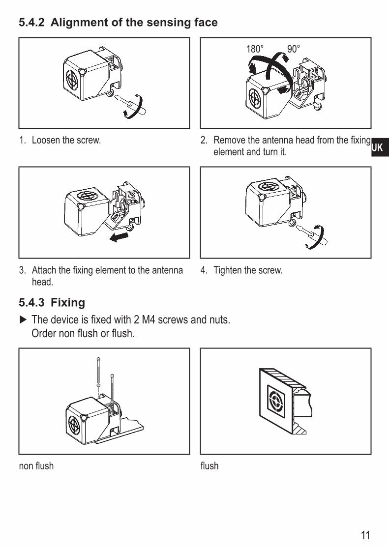
5.4.2 Alignment of the sensing face
180° 90°
1� Loosen the screw� 2� Remove the antenna head from the fixing element and turn it�
3� Attach the fixing element to the antenna head�
4� Tighten the screw�
5.4.3 Fixing ► The device is fixed with 2 M4 screws and nuts� Order non flush or flush�
non flush flush

12
5.4.4 Mounting distances
� �
�
Operating mode Distance side (A) Distance front (B)Reading only ≥150mm ≥150mmFor reading and writing ≥300mm ≥300mm
5.4.5 Positioning of the ID tags
E80311 E80312 E80317 E80318 E80319 E80320
1
E80322
1: front side

13
UK
5.4.6 Orientation of the ID tags
���
1: antenna axis DTA20x = ID tag axis2: middle of the antenna DTA20x = middle of the ID tag
5.4.7 Read/write distances Installation read/write head
ID tag Type Non flush Flush in metal
E80311 25 22
E80312 25 22E80317 35 28
E80318 55 36
E80319 65 45
E80320 60 40
E80322 55 36
All indications apply to static read/write operations� If not otherwise stated they refer to ID tag installation in a non-metallic environment� All indications in mm�
14
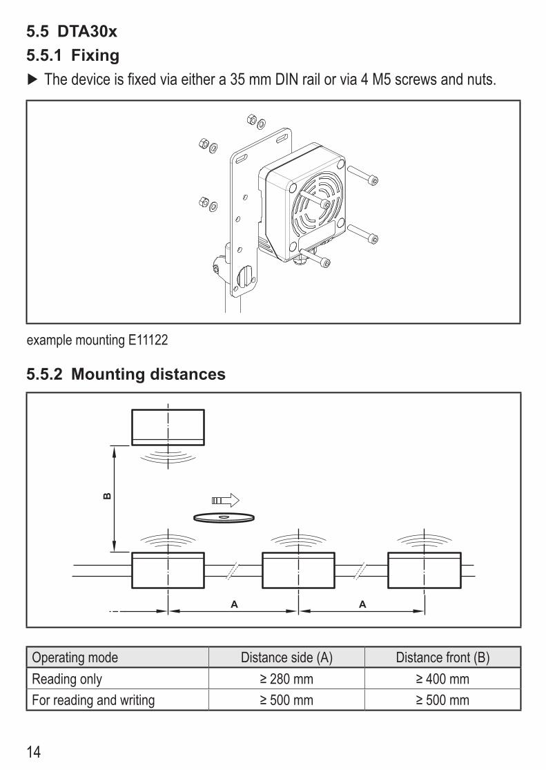
5.5 DTA30x5.5.1 Fixing
► The device is fixed via either a 35 mm DIN rail or via 4 M5 screws and nuts�
example mounting E11122
5.5.2 Mounting distances
� �
�
Operating mode Distance side (A) Distance front (B)Reading only ≥280mm ≥400mmFor reading and writing ≥500mm ≥500mm
15
UK
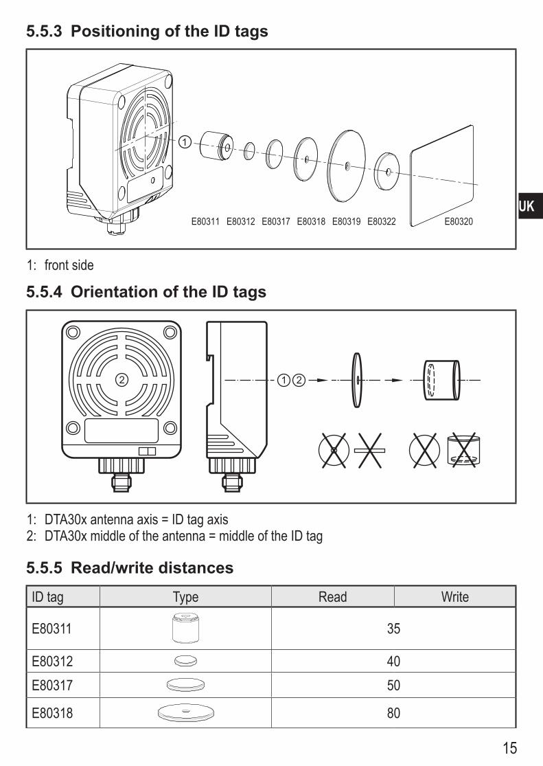
5.5.3 Positioning of the ID tags
1
E80311 E80312 E80317 E80318 E80319 E80320E80322
1: front side
5.5.4 Orientation of the ID tags
� ��
1: DTA30x antenna axis = ID tag axis2: DTA30x middle of the antenna = middle of the ID tag
5.5.5 Read/write distances ID tag Type Read Write
E80311 35
E80312 40E80317 50
E80318 80

16
ID tag Type Read Write
E80319 110
E80320 90
E80322 80
All indications apply to static read/write operations� If not otherwise stated they refer to ID tag installation in a non-metallic environment�All indications in mm�
5.5.6 Rotating plug insertThe plug insert can be rotated in steps of 45°�
1� Loosen nut� 2� Remove plug insert and rotate�
3� Tighten nut�
17
UK
6 Electrical connection ATTENTION The unit must be connected by a qualified electrician�Device of protection class III (PC III) The electric supply must only be made via PELV/SELV circuits�
► Disconnect power before connecting the unit�
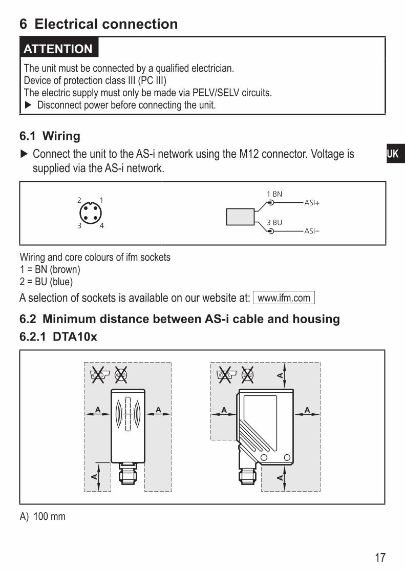
6.1 Wiring ► Connect the unit to the AS-i network using the M12 connector� Voltage is supplied via the AS-i network�
�
� �
�
ASI+
ASI
1
3
BN
BU
Wiring and core colours of ifm sockets1 = BN (brown)2 = BU (blue)A selection of sockets is available on our website at: www�ifm�com
6.2 Minimum distance between AS-i cable and housing6.2.1 DTA10x
�� � �
���
A) 100 mm

18
6.2.2 DTA20x
���
�
��
�
�
A) 50 mmB) 100 mm
6.2.3 DTA30x
��
�
�
�
�
�
�
A) 250 mmB) 500 mm
19
UK
6.3 cULusFor units with cULus approval and the scope of validity cULus:
► Supply the device from an isolating transformer having a secondary UL-listed fuse rated a) 5 A at voltages of 0���20 V rms (0���28�3 V p ) b) 100/V p at voltages of 20���30 V rms (28�3���42�4 V p )
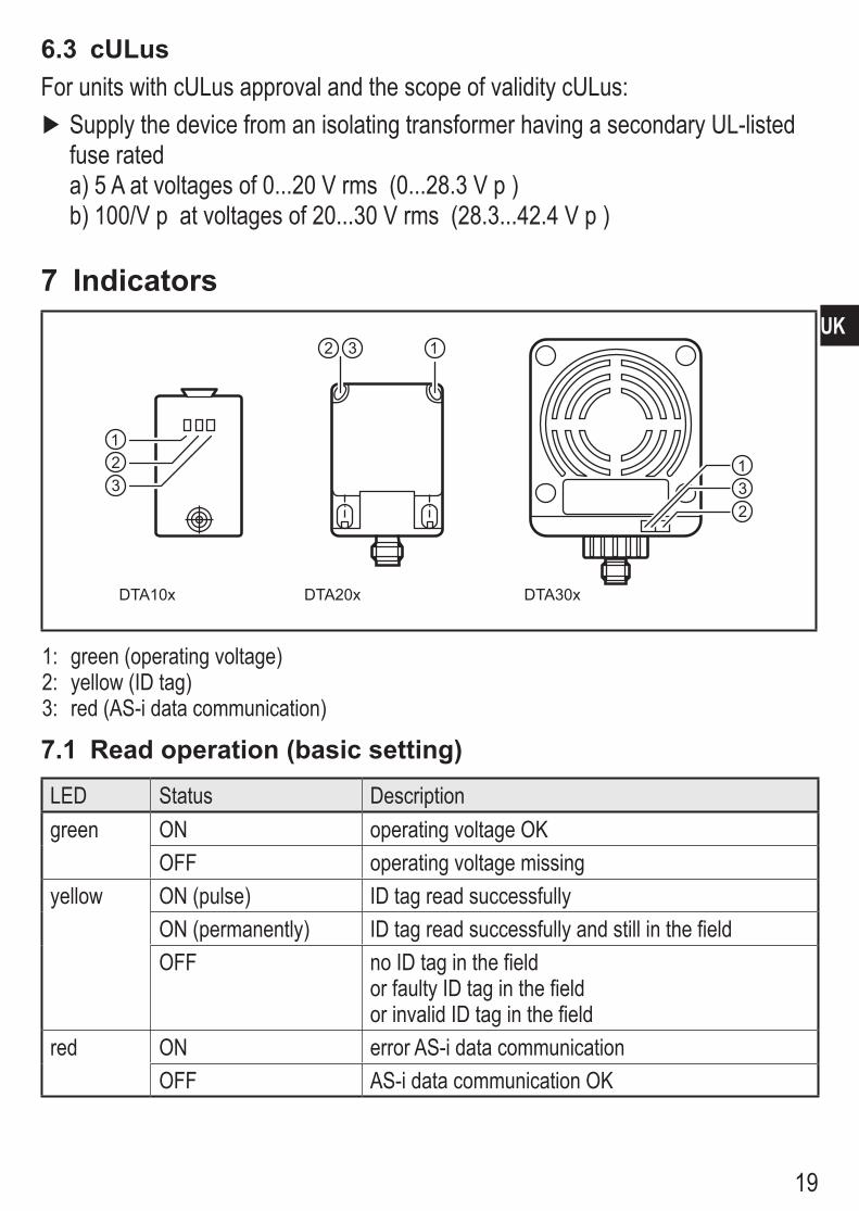
7 Indicators
������ ������������
���
���
�� �
1: green (operating voltage)2: yellow (ID tag)3: red (AS-i data communication)
7.1 Read operation (basic setting)LED Status Descriptiongreen ON operating voltage OK
OFF operating voltage missingyellow ON (pulse) ID tag read successfully
ON (permanently) ID tag read successfully and still in the fieldOFF no ID tag in the field
or faulty ID tag in the field or invalid ID tag in the field
red ON error AS-i data communicationOFF AS-i data communication OK

20
7.2 Write operation (only DTA100, DTA200, DTA300)LED Status Descriptiongreen/red ON/OFF like read operationyellow ON (pulse) ID tag written successfully
OFF no ID tag in the field or faulty ID tag in the field or invalid ID tag (wrong identification)
yellow 500 ms flashing writing of the ID tag not possible – ID tag not formatted – ID tag not in the detection zone – ID tag protected by lock bit – value outside the value range – invalid command

21
UK
8 Operation8.1 Basic settings in the AS-i networkParameter Read/write head Read head
DTA100, DTA200, DTA300
DTA101, DTA201, DTA301
AS-i profile 7�4 7�3I/O code 7 7ID code 4 3Extended ID2 code C CID1 code for code value F FSlave address (factory setting) 0 0
Code values in hex format
8.2 AddressingThe read/write head is addressed using an addressing unit (e�g� AC1144), the master or the AS-i software of the host (the components must support the AS-i version 2�1)�
► Assign an address between 1 and 31�
8.3 Analogue value representationFor the AS-interface the read/write head is a slave having an analogue input with the transmission protocol to the profile 7�4 or 7�3 (see above)� If the master operates to the master profile M3 or M4, it automatically detects the read/write head and supports the profile 7�4�For the analogue value transmission the profiles 7�3 and 7�4 are identical�
8.4 Assignment of the data bitsIn one transmission cycle the following data is transferred in data triples:
E1 E2 E3 D16 D15 D14 D13 D12 D11 D10 D9 D8 D7 D6 D5 D4 D3 D2 D1 O V
extension bits
(static 0)user data bits
Additional information bits:O = overflow bit (is set with the values 7FFF and 8000 hex�, otherwise 0) V = valid bit (is set with a valid value)

22
8.5 Code value representation using the data bits D16...D1The ID value is represented as a signed 16-bit number�
Range Decimal Hexfrom to from to
Value range 0 32767 0 7FFFMessage range -1 -32768 FFFF 8000
Value 0 = no ID tag in the reading range or ID tag not detected
8.6 Additional functions to the AS-i profile 7.4(Applies only to read/write heads)
Function, description DTA100 DTA200 DTA300Read ID string reading AS-i slave information ● ● ●Read diagnosis string reading statistics via read/write processes ● ● ●Read parameter string reading back data from the ID tag – ● ●Write parameter string writing data on the ID tag ● ● ●requesting data from the ID tag – ● ●
●=functionimplemented
Description, examples and software for various controllers at: www�ifm�com

23
UK
9 Dimensions9.1 DTA10x
5
41
4,517
56
17
4,25,5
M12x1
24
5570
53,5
9.2 DTA20x
��
��
��
��
���
����
�� �
��
��
���
���
����

24
9.3 DTA30x
��
��
��
�����
��
������
���
��
���
��
��
��
All indications in mm
10 Technical dataThe data sheets are available on our website at: www�ifm�com
11 Maintenance, repair and disposal ► Do not open the housing, as the device does not contain any components which must be maintained by the user� The device must only be repaired by the manufacturer�
► Dispose of the device in accordance with the national environmental regulations�
12 Approvals/standards12.1 Radio approvals12.1.1 OverviewThe overview of the approval status of a unit is available on our website at www�ifm�com�12.1.2 EuropeUse in all EU countries

25
UK
12.1.3 USAFCC note: This device complies with Part 15 of the FCC Rules� Operation is subject to the following two conditions:1� This device must not cause harmful interference, and2� this device must accept any interference received, including interference that
may cause undesired operation�Changes or modifications made to this equipment not expressly approved by ifm may void the FCC authorization to operate this equipment�NOTE: This equipment has been tested and found to comply with the limits for a Class A digital device, pursuant to part 15 of the FCC Rules� These limits are designed to provide reasonable protection against harmful interference when the equipment is operated in a commercial environment� This equipment generates, uses and can radiate radio frequency energy and, if not installed and used in accordance with the instructions, may cause harmful interference to radio communications� Operation of this equipment in a residential area is likely to cause harmful interference in which case the user will be required to correct the interference at his own expense�12.1.4 CanadaIC note:This device complies with Industry Canada license-exempt RSS standards� Operation is subject to the following two conditions:1� The device may not cause interference, and 2� the user of the device must accept any interference received, including
interference that may cause undesired operation�12.1.5 TaiwanAdministrative Regulations on Low Power Radio Wave Devices warning Article 12Unless granted permission by NCC, no company, firm, or user shall alter the frequency, increase the transmitting power, or alter the original design characteristics or operating functions of an approved low-power radio-frequency device�

26
Article 14Low-power radio-frequency devices shall not affect aircraft security nor interfere with legal communications� If such interference occurs, the user shall immediately cease operating the device until improvement is made and the interference no longer exists�Legal communications refers to the wireless telecommunication operations that comply with the Telecommunications Act� Low-power radio-frequency devices must accept any interference received from legal communications and ISM radio wave devices�12.1.6 AustraliaUse in Australia: 12.1.7 Singapore
Complies with IDA Standards
DB 103032
The “Equipment Registration” is available on our website at: www�ifm�com
12.1.8 EC declaration of conformityifm electronic gmbh hereby declares that the DTA10x / DTA20x / DTA30x radio system corresponds to the directive 2014/53/EU� You can find the EC declaration of conformity on our website at: www�ifm�com�

27
UK