installation instructions magnum grip stealth pro … · magnum grip stealth pro bandit shifter...
TRANSCRIPT

WORK SAFELY! For maximum safety, perform this installation on a clean, level surface and with the engine turned off. Place blocks or wedges in front of and behind both rear wheels to prevent movement in either direction. CAUTION: To avoid any possibility of bodily injury or damage to vehicle, do not attempt installation until you are confident that the vehicle is safely secured and will not move.
IMPORTANT: You must first install the shifter cable and an air slave cylinder or electric solenoid onto the shifter before positioning it in your vehicle. This is to insure that you allow for proper clearance at the rear of the shifter for these components before you permanently mount the shifter body into the vehicle. Mounting the shifter first without the cable and the air slave cylinder attached can cause possible interference from frame rails or other components. Poor cable routing and cable binding will result in poor shifter operation. INSTALLING THE SHIFTER CABLE
Technical Support (707) 544‐4761 1 www.bmracing.com
Installation Instructions MAGNUM GRIP STEALTH PRO BANDIT SHIFTER
Fits: 1962-1973 GM Powerglide w/standard or reverse pattern manual valve body
Catalog # 81113
1. Pull the shifter stick all the way back to the Low gear position, the position furthest from the red reverse lockout release lever. Remove the five countersunk screws from the B&M Magnum Grip Pro Bandit Shifter cover.
Selector Trigger
2. Locate the cable attachment pin at the rear of the shifter stick. The pin is visible just under the black shift pattern gate plate. Do not remove the black gate plate
cable attachment pin
INSTALLING THE NEUTRAL SAFETY SWITCH WIRES 6. The smallest hole in the rear of the shifter body is 13/64", it will serve as the exit for the jacketed neutral safety switch wires. Since this switch is a breaker that keeps the starter from engaging until the switch is closed in Neutral or Park, the color of the wires is not critical. It is only being used to break the 12V wire from the starter switch to the small wire on the starter solenoid. If your wiring is different, follow the instructions that pertain to your specific wiring layout.
Technical Support (707) 544‐4761 2 www.bmracing.com
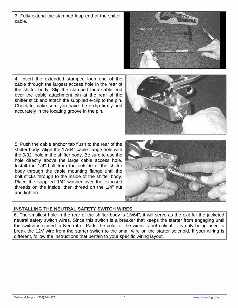
3. Fully extend the stamped loop end of the shifter cable.
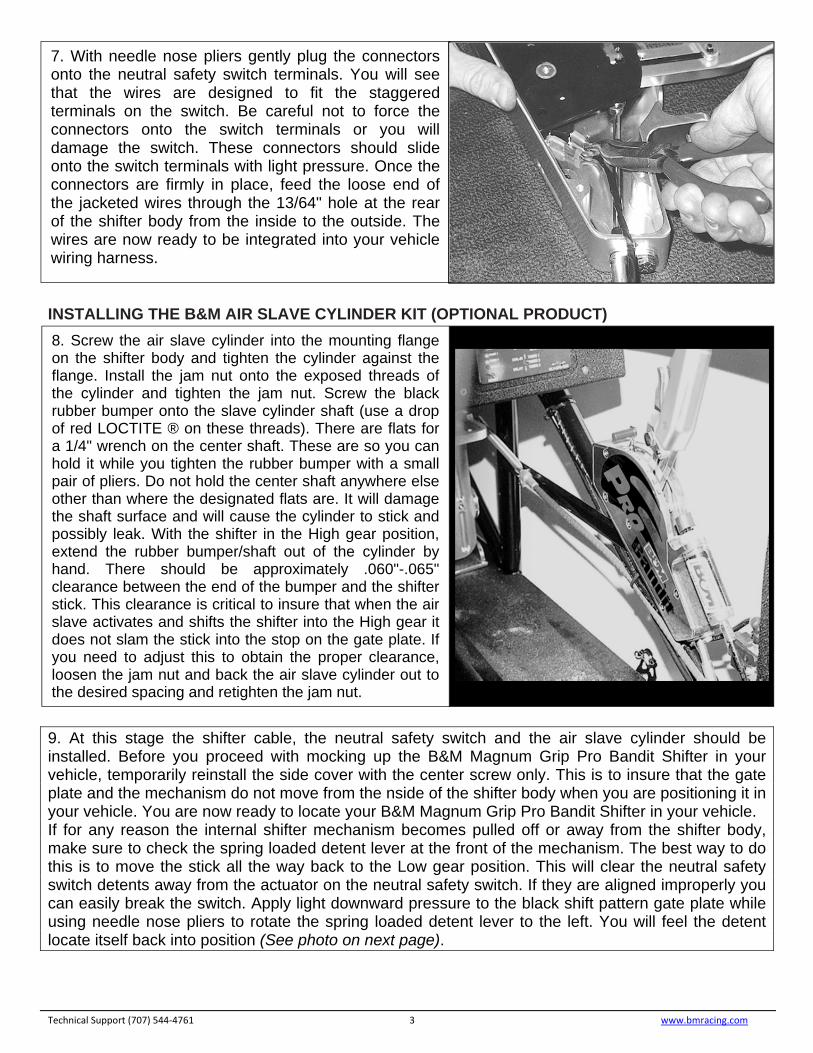
4. Insert the extended stamped loop end of the cable through the largest access hole in the rear of the shifter body. Slip the stamped loop cable end over the cable attachment pin at the rear of the shifter stick and attach the supplied e-clip to the pin. Check to make sure you have the e-clip firmly and accurately in the locating groove in the pin.
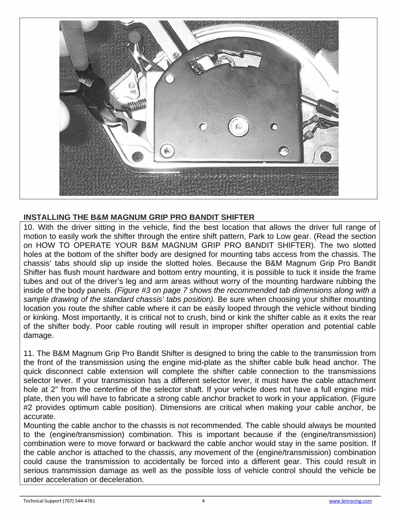
5. Push the cable anchor tab flush to the rear of the shifter body. Align the 17/64" cable flange hole with the 9/32" hole in the shifter body. Be sure to use the hole directly above the large cable access hole. Install the 1/4" bolt from the outside of the shifter body through the cable mounting flange until the bolt sticks through to the inside of the shifter body. Place the supplied 1/4" washer over the exposed threads on the inside, then thread on the 1/4" nut and tighten.
INSTALLING THE B&M AIR SLAVE CYLINDER KIT (OPTIONAL PRODUCT) 9. At this stage the shifter cable, the neutral safety switch and the air slave cylinder should be installed. Before you proceed with mocking up the B&M Magnum Grip Pro Bandit Shifter in your vehicle, temporarily reinstall the side cover with the center screw only. This is to insure that the gate plate and the mechanism do not move from the nside of the shifter body when you are positioning it in your vehicle. You are now ready to locate your B&M Magnum Grip Pro Bandit Shifter in your vehicle. If for any reason the internal shifter mechanism becomes pulled off or away from the shifter body, make sure to check the spring loaded detent lever at the front of the mechanism. The best way to do this is to move the stick all the way back to the Low gear position. This will clear the neutral safety switch detents away from the actuator on the neutral safety switch. If they are aligned improperly you can easily break the switch. Apply light downward pressure to the black shift pattern gate plate while using needle nose pliers to rotate the spring loaded detent lever to the left. You will feel the detent locate itself back into position (See photo on next page).
Technical Support (707) 544‐4761 3 www.bmracing.com
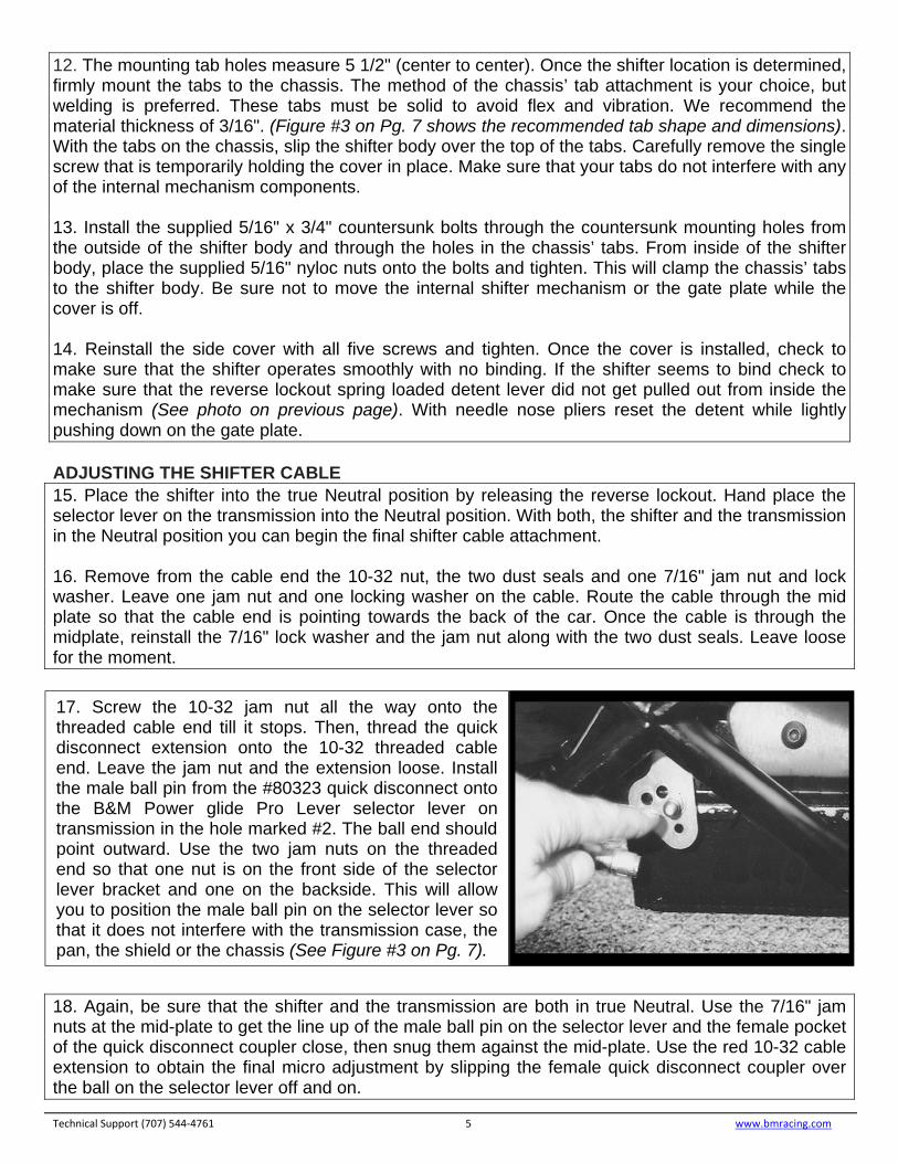
7. With needle nose pliers gently plug the connectors onto the neutral safety switch terminals. You will see that the wires are designed to fit the staggered terminals on the switch. Be careful not to force the connectors onto the switch terminals or you will damage the switch. These connectors should slide onto the switch terminals with light pressure. Once the connectors are firmly in place, feed the loose end of the jacketed wires through the 13/64" hole at the rear of the shifter body from the inside to the outside. The wires are now ready to be integrated into your vehicle wiring harness.
8. Screw the air slave cylinder into the mounting flange on the shifter body and tighten the cylinder against the flange. Install the jam nut onto the exposed threads of the cylinder and tighten the jam nut. Screw the black rubber bumper onto the slave cylinder shaft (use a drop of red LOCTITE ® on these threads). There are flats for a 1/4" wrench on the center shaft. These are so you can hold it while you tighten the rubber bumper with a small pair of pliers. Do not hold the center shaft anywhere else other than where the designated flats are. It will damage the shaft surface and will cause the cylinder to stick and possibly leak. With the shifter in the High gear position, extend the rubber bumper/shaft out of the cylinder by hand. There should be approximately .060"-.065" clearance between the end of the bumper and the shifter stick. This clearance is critical to insure that when the air slave activates and shifts the shifter into the High gear it does not slam the stick into the stop on the gate plate. If you need to adjust this to obtain the proper clearance, loosen the jam nut and back the air slave cylinder out to the desired spacing and retighten the jam nut.
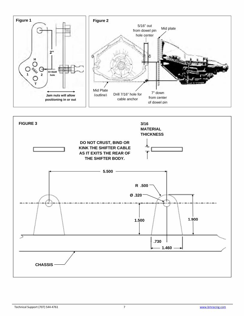
INSTALLING THE B&M MAGNUM GRIP PRO BANDIT SHIFTER 10. With the driver sitting in the vehicle, find the best location that allows the driver full range of motion to easily work the shifter through the entire shift pattern, Park to Low gear. (Read the section on HOW TO OPERATE YOUR B&M MAGNUM GRIP PRO BANDIT SHIFTER). The two slotted holes at the bottom of the shifter body are designed for mounting tabs access from the chassis. The chassis’ tabs should slip up inside the slotted holes. Because the B&M Magnum Grip Pro Bandit Shifter has flush mount hardware and bottom entry mounting, it is possible to tuck it inside the frame tubes and out of the driver’s leg and arm areas without worry of the mounting hardware rubbing the inside of the body panels. (Figure #3 on page 7 shows the recommended tab dimensions along with a sample drawing of the standard chassis’ tabs position). Be sure when choosing your shifter mounting location you route the shifter cable where it can be easily looped through the vehicle without binding or kinking. Most importantly, it is critical not to crush, bind or kink the shifter cable as it exits the rear of the shifter body. Poor cable routing will result in improper shifter operation and potential cable damage. 11. The B&M Magnum Grip Pro Bandit Shifter is designed to bring the cable to the transmission from the front of the transmission using the engine mid-plate as the shifter cable bulk head anchor. The quick disconnect cable extension will complete the shifter cable connection to the transmissions selector lever. If your transmission has a different selector lever, it must have the cable attachment hole at 2" from the centerline of the selector shaft. If your vehicle does not have a full engine mid-plate, then you will have to fabricate a strong cable anchor bracket to work in your application. (Figure #2 provides optimum cable position). Dimensions are critical when making your cable anchor, be accurate. Mounting the cable anchor to the chassis is not recommended. The cable should always be mounted to the (engine/transmission) combination. This is important because if the (engine/transmission) combination were to move forward or backward the cable anchor would stay in the same position. If the cable anchor is attached to the chassis, any movement of the (engine/transmission) combination could cause the transmission to accidentally be forced into a different gear. This could result in serious transmission damage as well as the possible loss of vehicle control should the vehicle be under acceleration or deceleration.
Technical Support (707) 544‐4761 4 www.bmracing.com
12. The mounting tab holes measure 5 1/2" (center to center). Once the shifter location is determined, firmly mount the tabs to the chassis. The method of the chassis’ tab attachment is your choice, but welding is preferred. These tabs must be solid to avoid flex and vibration. We recommend the material thickness of 3/16". (Figure #3 on Pg. 7 shows the recommended tab shape and dimensions). With the tabs on the chassis, slip the shifter body over the top of the tabs. Carefully remove the single screw that is temporarily holding the cover in place. Make sure that your tabs do not interfere with any of the internal mechanism components. 13. Install the supplied 5/16" x 3/4" countersunk bolts through the countersunk mounting holes from the outside of the shifter body and through the holes in the chassis’ tabs. From inside of the shifter body, place the supplied 5/16" nyloc nuts onto the bolts and tighten. This will clamp the chassis’ tabs to the shifter body. Be sure not to move the internal shifter mechanism or the gate plate while the cover is off. 14. Reinstall the side cover with all five screws and tighten. Once the cover is installed, check to make sure that the shifter operates smoothly with no binding. If the shifter seems to bind check to make sure that the reverse lockout spring loaded detent lever did not get pulled out from inside the mechanism (See photo on previous page). With needle nose pliers reset the detent while lightly pushing down on the gate plate. ADJUSTING THE SHIFTER CABLE 15. Place the shifter into the true Neutral position by releasing the reverse lockout. Hand place the selector lever on the transmission into the Neutral position. With both, the shifter and the transmission in the Neutral position you can begin the final shifter cable attachment. 16. Remove from the cable end the 10-32 nut, the two dust seals and one 7/16" jam nut and lock washer. Leave one jam nut and one locking washer on the cable. Route the cable through the mid plate so that the cable end is pointing towards the back of the car. Once the cable is through the midplate, reinstall the 7/16" lock washer and the jam nut along with the two dust seals. Leave loose for the moment. 18. Again, be sure that the shifter and the transmission are both in true Neutral. Use the 7/16" jam nuts at the mid-plate to get the line up of the male ball pin on the selector lever and the female pocket of the quick disconnect coupler close, then snug them against the mid-plate. Use the red 10-32 cable extension to obtain the final micro adjustment by slipping the female quick disconnect coupler over the ball on the selector lever off and on.
Technical Support (707) 544‐4761 5 www.bmracing.com
17. Screw the 10-32 jam nut all the way onto the threaded cable end till it stops. Then, thread the quick disconnect extension onto the 10-32 threaded cable end. Leave the jam nut and the extension loose. Install the male ball pin from the #80323 quick disconnect onto the B&M Power glide Pro Lever selector lever on transmission in the hole marked #2. The ball end should point outward. Use the two jam nuts on the threaded end so that one nut is on the front side of the selector lever bracket and one on the backside. This will allow you to position the male ball pin on the selector lever so that it does not interfere with the transmission case, the pan, the shield or the chassis (See Figure #3 on Pg. 7).

Carefully check to make sure that the lever is not being pulled forward or backward (see photo below). As you check each gear position, remove the quick disconnect coupler from the selector lever ball and shift the shifter and the transmission separately. Carefully slip the quick disconnect over the ball at each gear position. This adjustment technique will keep you from damaging the cable should the adjustment be off slightly. There may be some backlash in the cable when you’re checking the adjustment. This is normal. This comes from the bending of the cable during routing. The more bends, the more backlash. Keep your bends to a minimum for best performance. Do your best to find the most neutral adjustment. When finished, be sure to tighten all the jam nuts thoroughly. If adjustment does not seem accurate, be sure that you have the male ball in the proper #2 hole on the selector lever of the transmission. If you are not using a B&M Powerglide Pro Lever the proper selector radius is 2" from the center of the selector lever shaft. Always start your adjustment process with the shifter in Neutral and the transmission in Neutral. (Do not use Park to begin adjustment). HOW TO OPERATE YOUR MAGNUM GRIP PRO BANDIT SHIFTER This example of the Magnum Grip Pro Bandits operation is for use with the Powerglide transmissions utilizing a forward pattern valve body only. The gate plate is the same for a Powerglide with a reverse pattern valve body, the only change is that the Low gear and High gear positions switch. Other gate plate patterns are available. The available patterns and their respective part numbers are listed at the end of these installation instructions. From the Park position, squeeze the trigger to allow the release of Park lock and pull the stick back. The first detent will be the Reverse position. The second detent will be Neutral. The reverse lockout lever function is between the Reverse position and the Neutral position. The trigger is not required to pull the stick back to Low gear from Neutral. The third detent will be the High gear position and the fourth detent will be the Low gear position. From Low gear, to shift forward to High gear just push the stick forward, this gate is accessible without having to squeeze the trigger. From High gear position to access Neutral, squeeze the trigger and push the stick forward, this is Neutral for drive around purposes. For true Neutral, you must push the red reverse lockout lever forward. (Do not hold your hand on the shifter stick. The stick will move forward internally by the spring loaded mechanism). Once the lockout lever is forward and the shifter stick has automatically clicked forward. The lockout mechanism will now stay open on its own, with no assistance from the driver. At this point the shifter is in the true Neutral position. To access Reverse from the true Neutral position, simply push the shifter stick forward, without squeezing the trigger. Squeezing the trigger will open the next gate, which will be the Park position. If you wish to rearm the reverse lockout from the true Neutral position, pull back slightly on the shifter stick and you will see the lockout lever snap back into the lock position. Technical Support (707) 544‐4761 6 www.bmracing.com
Technical Support (707) 544‐4761 7 www.bmracing.com
Jam nuts will allow
positioning in or out
2”
#2 B&M hole
H
2
T
1
Mid Plate (outline) Drill 7/16” hole for
cable anchor
7” down from center of dowel pin
5/16” out from dowel pin
hole center
Mid plate
Figure 1 Figure 2
DO NOT CRUST, BIND OR KINK THE SHIFTER CABLE AS IT EXITS THE REAR OF
THE SHIFTER BODY.
3/16 MATERIAL THICKNESS
5.500
1.500 1.900
.730
1.460
R .500
Ø .320
CHASSIS
FIGURE 3

IMPORTANT: RETAIN THESE INSTRUCTIONS FOR FUTURE REFERENCE Technical Service
A highly trained technical service department is maintained by Hurst Performance to answer your technical questions, provide additional product information and offer various recommendations.
Technical service calls, correspondence, and warranty questions should be directed to:
B&M Racing & Performance Products
(707) 544-4761
www.bmracing.com
Technical Support (707) 544‐4761 8 www.bmracing.com