installation instructions...installation instructions pool ranger swimming pool & spa products...
TRANSCRIPT

Installation Instructions
POOL RANGER Swimming Pool & Spa Products Page 1
w: poolranger.com • p: 1300 731 905
S A L T W A T E R C H L O R I N A T O R S
MAGNA-CHLOR SALT WATER CHLORINATION SYSTEM
STANDARD - AC-15, AC-20, AC-25, AC-35, AC-50 REVERSE POLARITY - RP-15, RP-20, RP-25, RP-35, RP-50
WITH TIME CLOCKS(BATTERY BACKUP OPTIONAL)
POOL RANGER Swimming Pool & Spa Products Page 2
w: poolranger.com • p: 1300 731 905
THE MAGNA-CHLOR SALT WATER CHLORINATION SYSTEMCongratulations on your choice of an MAGNA-CHLOR salt water chlorinator system for your swimming pool. The MAGNA-CHLOR salt water chlorinator you have purchased is designed for easy operation and maintenance. By following these instructions you are assured years of trouble free operation.
These instructions have been compiled and produced to help you get the maximum results from your unit and to assist you to fully understand and correctly operate your MAGNA-CHLOR salt water chlorinator.
Please take the time to read these instructions thoroughly before attempting to operate your unit. Should you require additional information or further assistance, please do not hesitate to contact us.
SPECIAL NOTEPlease remember that your salt water chlorinator is not designed to chemically maintain your pool water and keep it balanced, but rather to produce chlorine from a mild salt solution within the water.
We encourage regular water testing, balancing and correction if and when required to maintain the recommended stability levels of your pool water. This is a vital part of a complete maintenance program and will ensure trouble free chlorinator performance as well as a healthy and sparkling clean pool.
ADDITION OF SALTFor best results, the salt concentration in the pool water is required to be within an average range of approximately 4,500 - 5,500 parts per million (ppm). These figures are temperature dependant. In the summer time, as water temperatures rise, salt levels may require slight reduction while in winter time the reverse may be true to allow optimum performance of your unit.
The amount of salt required to achieve the desired level is determined by the capacity of the pool. By measuring your pool and multiplying the average length by the average width in cubic metres. Multiply this by 4.2 to calculate the amount of salt (in kilograms) needed to adequately achieve the required dosage for your pools capacity.
For example: Pool size is 9 metres by 4.5 metres by 1.6 metres in depth.
Multiply 9 x 4.5 x 1.6 = 64.8 (cubic metres of water)
Multiply 64.8 x 4.2 = 272.16 (Salt required in kg)
Using only refined swimming pool salt, add the desired quantity to the swimming pool water. To assist in the rapid dissolving and mixing, sweep or brush the solids until they are fully dissolved. Undissolved salt may result in staining your pool finish.
As salt is heavier than water it will continue to lie at the deepest point of your pool, even though the salt granules themselves have fully dissolved. In order to ensure adequate and permanent distribution of salt throughout your pool water, we recommend additional sweeping and filter operation over a 12 - 24 hour period.
Whilst adding the original salt and prior to commissioning your MAGNA-CHLOR unit, and when adding future salt supplies to your pool, please ensure that your chlorinator power supply is switched off to prevent overload situations and/or damage to the cell electrode plates or power supply.

POOL RANGER Swimming Pool & Spa Products Page 3
w: poolranger.com • p: 1300 731 905
SPECIAL NOTEContrary to popular belief, the action of your MAGNA-CHLOR salt water chlorinator does not use up the salt content of your pool water. As the water passes over the cell plates, the salt is electrolysed and converted into sodium hypochlorite (Chlorine).
This sanitises your pool water and converts back into salt - basically a never-ending cycle. However, salt loss will occur through swimmer action, filter back washing and wet weather conditions.
The salt needs to be replaced periodically for the chlorinator to operate at maximum efficiency.
Your local pool shop can advise you the correct salt dosage required to maintain saline levels at recommended guidelines. IDEAL SALT SOLUTION IS 5000ppm.
WATER BALANCEAs previously advised, for best performance and operation of your MAGNA-CHLOR salt water chlorination system, certain water balances must be maintained within your swimming pool. Please check your pool water and ensure that your chemical balances are within the following guidelines.
pH 7.2 - 7.4
Total Alkalinity 90 - 150 ppm
Cyanuric Acid 40 - 65 ppm
Salt 4,500 - 5,500 ppm
Chlorine 1.5 - 2.0 ppm
Adjust your pool water balance to achieve the above levels. Your local pool shop can assist to give you the accurate readings and aid in correct dosages as necessary.
SPECIAL NOTE ON CHLORINEYour salt water chlorinator is not designed to bring your pool from a zero chlorine reading to an acceptable level but rather to maintain acceptable levels. Should it become necessary due to unforeseen circumstances (such as the unlikely event of chlorinator malfunction, severe weather patterns, or massive use of the swimming pool) that you find the pool requires additional chlorine then it should be manually added, rather than running your filter and chlorinator excessively to replace the lost chlorine. Doing this could put your chlorinator and cell under unnecessary strain which could shorten their lives.
In situations such as this we recommend the use of liquid chlorine (sodium hypochlorite) to supplement and maintain chlorine levels. The use of dry chlorine (calcium hypochlorite) is not recommended unless liquid chlorine is unavailable and even then only in limited amounts.
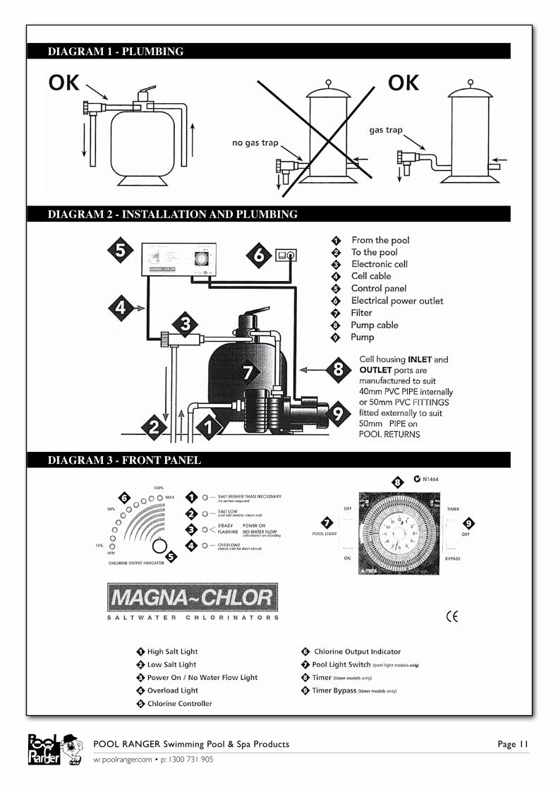
FITTING THE CHLORINATOR CELL HOUSINGThe MAGNA-CHLOR salt water cell housing must be plumbed into the return line of the pool filter system after the filter and any diversion valves. Please refer to the installation diagram and plumbing outline for the correct method of installation. (Diagram 1 & 2).

POOL RANGER Swimming Pool & Spa Products Page 4
w: poolranger.com • p: 1300 731 905
INSTALLING THE POWER SUPPLYThe MAGNA-CHLOR power supply is mounted on a wall using the mounting bracket and fittings supplied. After securing the bracket in the appropriate position relative to your needs, the power supply is hung on the bracket and locked into position by ensuring that the unit slips into the slots provided on the mounting bracket.
It is preferable that the power supply is mounted in a location where it is protected from accidental water spray and inclement weather. It is strongly recommended that the unit is also protected and screened from harsh sun, but in such a way that air flows freely through the structure and does not impede the natural airflow through the power supply. You should also ensure that the power supply is not used as a shelf to store or pack objects, as this can also impede the air flow, causing overheating and/or damage to the unit that is not covered by warranty.
Mount the power supply so that you can see and reach the various controls and so that the cell lead has a comfortable margin to reach the cell terminal posts. Our recommendation is that the power supply is mounted slightly higher and to one side of the filter plant to allow easy access (refer to diagram 2).
POWER SUPPLY CONTROL FUNCTIONSYour MAGNA-CHLOR salt water chlorination system has been designed for easy operation and control.
The functions and controls (both standard and optional) and their various operations will give you a greater understanding and knowledge of the control and maintenance of both your MAGNA-CHLOR unit and your pool (refer to diagram 3 for controls).
CIRCUIT BREAKEREvery MAGNA-CHLOR chlorinator has a circuit breaker located on the right hand rear of the unit. It has been located so that it can be easily accessed with the flat of the hand without the necessity of removing the power supply unit from the mounting bracket.
The circuit breaker is designed to trip out in the event of a power surge or power overload. When tripped the centre button will pop out shutting down the unit to prevent damage. To reset and resume chlorination of your pool the centre button of the circuit breaker must be pressed in to allow normal operations to proceed. Mains power to the unit must be turned off prior to resetting the circuit breaker. Should the circuit breaker continue to trip after the exercise then you should consult your local representative for assistance.
ON/OFF SWITCH - NON TIMER MODELS ONLYThe on/off switch is located on the front panel and has been incorporated to allow you to switch off the chlorinator function should you so desire. Please note that this switch will only shut down the chlorinator operation. It will not affect the normal filter functions which will continue to operate at the pre selected times you have chosen.

POOL RANGER Swimming Pool & Spa Products Page 5
w: poolranger.com • p: 1300 731 905
PUMP OUTPUT SOCKETA 240 volt pump output power socket is supplied and located on the right hand underside of the power supply. Your pool pump power supply lead should be plugged into this socket so that when the time clock switches on at the designated times, both the salt water chlorinator and pool pump will activate in unison.
Do not attempt to operate the chlorinator power supply with the pool pump lead disconnected as this will lead to a gas build-up inside the cell housing causing it to overheat resulting in damage to your chlorinator equipment that is not covered by warranty. In extreme cases gas build-up may also cause the cell housing to rupture and explode, as it is not built to withstand this type of pressure, possibly resulting in personal injury.
The pump socket is designed to operate a single pool pump of maximum 1.5hp (horse power) only. Do not attempt to operate any equipment other than your pool pump from this socket as damage might occur to the power supply unit that is not covered under warranty.
WARNING INDICATOR LIGHTS(DIAGRAM 3 - ITEMS 1, 2, 3 & 4)
There are four (4) warning indicator lights located on the front of your chlorinator. These show at a glance the status of the chlorinator power supply and, when illuminated they indicate the situation the chlorinator’s electronic monitoring system has detected. The lights and their functions are listed below.
1. ORANGE LIGHT - SALT HIGHER THAN NECESSARY No action required.
When illuminated this indicates that you have exceeded recommended salt levels. As long as this is not causing your chlorinator to overload no further action or reduction of salt concentration is required at this point. No further salt should be added if this light is illuminated.
2. ORANGE LIGHT - STEADY CELL OFF Chlorinator on standby FLASHING SALT LOW Add salt and/or clean cellSTEADY - When illuminated in a STEADY continuous light your chlorine production has been switched off by turning the chlorine controller (Diagram 3 - Item 5) anti clockwise and your chlorinator power supply is now in a standby mode. Turn the chlorine controller clockwise to resume normal operation.
FLASHING - If the light is illuminated and FLASHING the monitoring system has detected low salt levels and this will need to be adjusted for the chlorinator to operate at maximum capacity. This light will also flash if the cell has reached a point where its output is below the normal operating output. Please refer to the section detailing the addition of salt to your pool.
CONTINUE TO THE NEXT PAGE...

POOL RANGER Swimming Pool & Spa Products Page 6
w: poolranger.com • p: 1300 731 905
3. RED LIGHT - STEADY POWER ON FLASHING NO WATER FLOW Chlorinator on standbySTEADY - During normal operation this light will remain STEADY, indicating that power is on and the chlorinator is operating correctly.
FLASHING - When FLASHING the monitoring system has detected a water flow problem and has shut down to prevent damage. It will also be accompanied by a beeping alarm alerting you of this situation. When the problem is rectified normal operation will resume.
4. RED LIGHT - STEADY OVERLOAD OFF NORMAL OPERATION In forward cycle FLASHING NORMAL OPERATION (RP Models Only) In reverse cycle.STEADY - When this light is illuminated and STEADY it will also be accompanied by a beeping alarm alerting you of the situation. The chlorinator has overloaded and shut down to prevent any damage. A direct short between two of the electrode plates coming into contact with each other could cause this, or a foreign object could be shorting out two or more plates. It can also be caused by a massively high concentration of salt in the pool water. Depending on the problem and rectification required, normal operation can proceed. Please note the chlorinator power supply must be switched off and then on again to reset the electronic circuitry and resume operations.OFF - When this light is off, the chlorinator is operating correctly in forward cycle mode.FLASHING - When illuminated and FLASHING the chlorinator is operating correctly in reverse cycle mode.
SPECIAL NOTE ON WARNING INDICATOR LIGHTS - RP MODELS ONLYWhen your chlorinator is operating in forward polarity cycle, light number 3 (Diagram 3, Item 3) is on and steady while light number 4 (Diagram 3, Item 4) is off.When your chlorinator is operating in reverse polarity cycle, light number 3 remains on and steady while light number 4 will flash.At the end of each cell operational cycle (or cell reverse), the power on/no water flow light and overload light (Diagram 3, Items 3 & 4) will ALTERNATE by flashing in a slow fashion for approximately thirty (30) seconds. This is the cell rinse procedure and is part of the normal operation, which occurs at each reverse cycle change of your MAGNA-CHLOR REVERSE POLARITY chlorinator. On completion normal operations in the next cycle will begin.Contrary to popular belief, during both normal and reverse cycle modes the chlorinator continues to manufacture chlorine, whilst at the same time the opposite polarity cell plates are being automatically cleaned.
CHLORINE CONTROLLER(DIAGRAM 3, ITEM 5)The chlorine controller regulates the amount of chlorine production relevant to the position it has been set to. By adjusting the chlorine controller clockwise you increase chlorine manufacture and by turning anti clockwise you reduce production. Do not attempt to turn the controller beyond its stops as this could cause damage to your unit which is not covered by warranty.

POOL RANGER Swimming Pool & Spa Products Page 7
w: poolranger.com • p: 1300 731 905
CHLORINE OUTPUT INDICATOR(DIAGRAM 3, ITEM 6)Your power supply is fitted with ten green indicator lights set in a crescent shaped information. During operation of your chlorinator these lights will illuminate to the position at which the chlorine controls have been adjusted. Working in conjunction with the chlorine controller you can increase or decrease chlorine output to suit your pool’s requirements. As you increase the output, (by turning the control knob clockwise), the corresponding lights will illuminate progressively to 100% (ten lights).You have full control of chlorine production merely by adjusting the chlorine controller and illuminating the number of lights to satisfy your chlorine demand. Each light represents 10% (one light) of capable chlorine production up to its maximum output of 100% (ten lights).
TIME CLOCK OPERATIONS - TIMER MODELS ONLY(DIAGRAM 3, ITEM 8)The standard timer when fitted to your chlorinator is designed to switch your equipment on and off at the times you have nominated.Your timer has a standard clock face and hands set in the clear centre section, whilst the outer grey bezel shows the hours in military style (24 hour) time. To set the clock to present time, place your finger on the clear centre bezel and slowly turn it clockwise to the desired time. Time of day can be set by clock hands or by lining up the outer grey numbers to the corresponding time of day, which is set at the red indicator line.Start and stop times are set by pushing in the small grey time setting elements at the extreme outside of the time clock face and exposing a red mark. Each element represents fifteen minutes and these should be positioned showing the red marks at the times you wish your filter plant and chlorinator to operate.With the elements pushed in and the red marks showing the timer will turn your equipment on when they reach the red indicator line. With the elements pushed out and the red marks not visible the time will turn your equipment off at the end of the red.The top left hand side of your time clock has provision for overriding the time settings. With the switch set to AUTO mode, the unit will switch at your designated times. With the switch set at ON, the timer will by-pass timer setting and run continuously. Remember to put this switch back to AUTO after using the by-pass function.To turn the unit and pump off during its timer cycle you will have to turn it off at the power point or isolation switch that your electrician may have fitted. If you use this method and interrupt power supply please remember to reset the time clock to present time when you reconnect the unit to the power.The top right corner of the timer has provision for setting the hertz (Hz) (this is a measurement of electrical frequency) to either 50 or 60. This has been factory pre-set at 50 Hz (for Australian conditions) and should not be moved. If it has been moved to 60 Hz your timer will lose time and should be resent to 50 Hz. CONTINUE TO NEXT PAGE..

POOL RANGER Swimming Pool & Spa Products Page 8
w: poolranger.com • p: 1300 731 905
SPECIAL NOTE ON TIMERSIf you require your MAGNA-CHLOR salt water chlorinator to be connected to a cheaper off peak tariff we recommend the use of an appropriate quartz time clock for that purpose. The unit may also be hard wired in however, in case of incorrect wiring or damage caused by modifications warranty will be void.We suggest that an appropriate quartz time clock (with battery backup) be fitted in lieu of the standard model to allow time of day to be maintained when power supply is interrupted.Quartz time clocks can be fitted at factory stage, or later at extra cost. Please see your MAGNA-CHLOR representative if you wish to have this done.Quartz time clocks are discernible by their model A-TB72Q marked on the lower left casing of the clock. In lieu of the 50 - 60 Hz switch, a power light is fitted indicating power to the timer and the chlorinator unit.
TIMER BY-PASS SWITCH - TIMER MODELS ONLY(DIAGRAM 3, ITEM 9)If your MAGNA-CHLOR chlorinator has a timer by-pass switch fitted you will find this located on the front panel on the right hand side of the time clock. This switch allows you to by-pass functions without the need to use the auto - on switch located in the timer frame. If this external switch is fitted to your MAGNA-CHLOR unit, then the internal timer switch must remain in the AUTO position and the timer by-pass functions are operated by utilising the external timer by-pass switch.Three functions are available: TIMER The time clock will automatically switch your pool equipment on or off
at your designated times. OFF The time clock will not switch, but normal time will be maintained. BY-PASS The clock has by-passed all designated functions and will operate the
pool equipment indefinitely. PLEASE NOTE: Return switch to timer position after using the off or by-pass functions.
UNDER WATER POOL LIGHTS - POOL LIGHT MODEL ONLYWhere requested, and as an optional extra, some MAGNA-CHLOR models have swimming pool under water light transformers fitted. This special transformer allows you to connect your pool light lead to the special connection supplied and operate them from the chlorinator power supply.The under water light lead is connected directly into the special light connector strip which is located on the underside of the chlorinator power supply. Connect the lead from your pool lights to the connector strip terminals by use of the two locating screws.The on/off switch (Diagram 3, Item 7) for the pools lights is located on the left hand side of the time clock. The pool light circuitry is protected by its own circuit breaker, which is located adjacent to the main circuit breaker at the rear of the unit.Operation of your pools lights is only through the on/off switch provided. Your chlorinator time clock will not switch your pool lights on or off at the designated pool filtration times.Pool light transformers are available in 12, 24 and 32 volt models. Please check to ensure that you have matched your pool light voltage to that supplied with your MAGNA-CHLOR chlorinator.
POOL RANGER Swimming Pool & Spa Products Page 9
w: poolranger.com • p: 1300 731 905
GENERAL CHLORINATOR OPERATIONBefore switching on your MAGNA-CHLOR salt water chlorination system please ensure that you have added the correct amount of pool salt, it has fully dissolved and is distributed throughout the pool water. (See ADDITION OF SALT section). Ensure that the base pool chemistry is at the recommended levels and the pool water is clean and crystal clear.Switch on the pool filter system and the MAGNA-CHLOR unit. At this point the MAGNA-CHLOR electronic display may register a water flow fault as the cell housing fills with water and an alarm (beeping) may activate. This is normal start up procedure and will cease as soon as the unit registers full and correct water flow throughout the electrodes. (See WATER BALANCE Section).With the chlorine controller knob (Diagram 3, Item 5) now turned fully clockwise to the maximum position the green chlorine output indicator lights will illuminate one after the other. With the correct amount of salt added to the pool water you should achieve a 100% (ten lights) reading. In this position the MAGNA-CHLOR chlorinator is producing maximum chlorine output.As previously stated, chlorine demand will differ from pool to pool due to bather load, water temperature or weather conditions and this must be taken into consideration. By testing for chlorine residuals on a regular basis you will quickly determine the chlorine state of your pool and what action you need to take to adjust it if required.After determining your particular pool’s chlorine needs, you can set the controller to the desired setting to achieve your chlorine requirements and/or adjust your daily running times. Normally once set, these controls do not require further adjustment except perhaps for the seasonal ones suggested earlier.Set your chlorine controller to achieve maximum and optimum results for your pool situation. Please remember that an over chlorinated pool is not a healthy pool, so it may not be necessary for you to run your chlorinator at maximum output to maintain recommended chlorine levels.Your MAGNA-CHLOR salt water chlorinator is fitted with a sophisticated electronic circuit board which is designed to minimise the need for manual operations and maximise cell life by constantly managing the correct operation of the power supply and electrolytic cells. In addition to the four warning lights, a warning alarm (beeper) has been installed to alert you of any problems that the electronic monitoring system has interpreted. The alarm will activate to alert you to any problems that have detected, and once rectified the unit will resume normal operations.
IMPORTANT SPECIAL NOTE FOR RP MODELS ONLYYour MAGNA-CHLOR reverse polarity monitoring system is factory pre set to reverse cycle at the completion of each 8 hours operational period. The circuitry is fitted with a microchip that measures the actual operating hours of the electrodes. When the chlorinator has operated for the total factory designated hours in one direction it will then change (reverse) cycle and operate in the opposite direction for the same operational time. This ensures that the electrode plates (+ and -) each receive the same operational time, therefore equalising the extending cell life, and ensuring adequate cleaning for each cycle.By maintaining a watch on the indicator and warning lights, keeping the cells in a clean state and chemically balancing your pool water regularly you are ensuring trouble free operation of you MAGNA-CHLOR chlorination unit with the least amount of effort.

POOL RANGER Swimming Pool & Spa Products Page 10
w: poolranger.com • p: 1300 731 905
CHLORINATOR RUNNING TIMESChlorinator running times will vary from pool to pool, and are dependent upon the situation they are installed into, pool size and the overall usage of the pool in general.Several factors will determine the operational time of the chlorinator to be able to produce sufficient chlorine for your pools requirements. TIME: The longer you run your filter plant and chlorinator, the more chlorine you will produce. RATE: The higher the chlorine output indicator lights up, the more chlorine is being produced. CELL CLEANLINESS: The cleaner the cell, the better the chlorine production rate. BASIC POOL CHEMISTRY: The more correctly maintained, the less chlorine waste.CLEANING THE ELECTROLYTIC CELLSFrom time to time it will become necessary to clean calcium and other deposits which will form on the chlorinator electrolytic cell plates. Cleaning maintenance of the cells will vary from one pool to the next depending on water conditions and calcium build up rate on the electrodes. Cleaning times will also vary from AC model to RP model with AC models requiring far more regular maintenance then RP models.This is because RP models are, to a large extent, self cleaning. However, it must be understood that proper maintenance of the electrodes is essential for optimum chlorine production, and longevity of cell life. We recommend that the chlorinator cells be cleaned on a regular and specified maintenance and cleaning program. This should always be done wearing the correct protective equipment.Cleaning of the cells is a very easy task. First mix a solution of one (1) part HCL (pool acid) to eight (8) parts of water. You should make sufficient to be able to immerse the cell completely but not the cell head or brass connectors. For safety please remember to add the pool acid to the required amount of water, not the water to the acid. Ensure that your container is deep enough to immerse the entire electrode plates within the solution.Switch off the pool filter and chlorinator system, and isolate the power to the unit. Close any shut-off valves that may be fitted to your system and, after ensuring connectors are not hot, gently ease the cell leads from their terminal posts.DO NOT TOUCH overheated connectors as burns to the fingers may result.Turn the locking ring on the cell housing anti clockwise so that the electrode bundle can now be removed from the cell housing. Immerse the cell plates into the pre mixed water/acid solution, where a chemical reaction occurs, causing the liquid in the container to bubble. This is a normal reaction as the calcium deposits are being cleaned from the electrode plates.It should take approximately eight to ten minutes for this process to be completed and the cells should then be cleansed of all deposits. If not, you may repeat the above step one more time, but not more than twice in the one cleaning session.DO NOT use any brushes, harsh scrubbing, chemical cleaners or attempt to scrape off the deposits as this can damage the electrode special coating, reducing cell life, and voiding warranty.After cleaning, rinse the electrode bundle in fresh water. Dry and clean the brass terminal posts and buff them to remove all traces of dirt and build up. Please ensure that the terminals (Black & Red) are firmly tightened before reinstalling your cell. Failure to do so may result in the overheating of the cell connectors on both the cell cap and the lead causing damage to your cell that is not covered by the warranty terms. CONTINUE TO NEXT PAGE...
POOL RANGER Swimming Pool & Spa Products Page 11
w: poolranger.com • p: 1300 731 905
Replace the cell into its housing, remembering to ensure that the cell terminal post with the red pole is uppermost. Tighten the cell locking ring by turning clockwise. Open any shut-off valves that you previously closed and now connect the cell leads to their respective terminal posts, remembering RED to RED pole and BLACK to BLACK pole, with the sensor lead to its special position. You are now ready to resume filter and chlorination operations.REMEMBER a clean electrolytic cell will extend the cell life as well as producing maximum chlorine without the necessity of running the power supply at continually higher settings. By keeping your cell in a clean state at all times you are effectively safe guarding your investment and maximizing the cell life of your salt water chlorinator.
SPECIAL NOTE ON CLEANING RP MODEL CELLSAlthough you have reverse cycle (Automatically Cell Cleaning) chlorinator, it is recommended from time to time that the cell be checked for any accumulation of calcium or other deposits that may have built up. During 8 hours reverse cycle a fine film of calcium builds up on the edges of the plates, but this should be automatically cleaned after every cycle. In some areas, the chemcial composition of the water can cause an excessive buildup of calcium on the plates in a shorter period of time than usual. This condition will require extra attention to ensure cleanliness of the cell. It is a good practice to check the cells occasionally for excessive build up, to ensure that the lead connections are clean and firmly tightened, that the electrode spacers are in place and to remove any other foreign objects that may have become trapped if necessary. We recommend cleaning the cell once or twice a year subject to your pool’s application and location. To clean the electrode (cell), please refer to CLEANING THE ELECTROLYTIC CELLS section.
WARRANTY AND SERVICEA three (3) year warranty is applied to the power supply and electrolytic cell on all MAGNA-CHLOR AC & RP model chlorinators, when used in a domestic application.Any model used in a commercial application is covered by a one (1) year warranty.This warranty applies to the original purchaser and is not transferable. All chlorinators are fully tested at the factory prior to being packed. If, within thirty-six (36) months of purchase, mechanical or electrical faults occurring due to bad workmanship or faulty components, then such parts will be repaired or replaced at no cost to the owner (including labour). No replacement parts will be provided without the return of the defective components and proof of purchase of the unit.The manufacture will not be liable for any consequential loss or damage caused by operation outside our prescribed limits as outlined in our instruction manual. Incorrect installation or connection to incorrect power supply, changing internal wiring for tariff connections, misuse, abuse, negligence, accidental damage, normal wear and tear, or damage caused by water entry are not covered by this warranty. In case of failure the complete unit should be returned to the manufacturer, distributor or one of our recognized service warranty agents, along with proof of purchase. Forward and return freight costs are the responsibility of the owner.PLEASE NOTE: unless specified, all warranty work is strictly factory repair.FOR ALL WARRANTY ENQUIRIES PLEASE CALL 1300 731 905.
POOL RANGER Swimming Pool & Spa Products Page 11
w: poolranger.com • p: 1300 731 905
DIAGRAM 1 - PLUMBING
DIAGRAM 2 - INSTALLATION AND PLUMBING
DIAGRAM 3 - FRONT PANEL