installation instructions for small seed option · 92 81 u d b f r l 88 92 81 figure 4 dismount smv...
TRANSCRIPT

Installation Instructions for Small Seed Optionfor 605NT, 606NT, 3P500, 3P600, 3P605NT, and 3P606NT Drills
Before Getting Started
Before you begin installation of your Small Seeds OptionKit, read these instructions carefully and check that allparts and tools in kit are accounted for. All hand andspecialty tools for installation are provided at owner’sexpense. Please retain these installation instructions forfuture reference and parts ordering information.
These installation instructions contain information forassembling the Small Seeds Option to the mainmachine. Please read all instructions in the OperatorManual for your drill thoroughly before proceeding. Youroperator manual includes information on operation,adjustment, troubleshooting, and maintenance for thisattachment (some manual sections do not apply to allaccessories).
Instructions contain information for all makes and modelsof the applicable machines.
General InformationThese instructions explain how to install a Small GrassSeeds (SGS) assembly on a compatible 5- or 6-foot drill.
The Small Seeds option adds the capability to meter thesmallest of seeds at rates more precise than using themain seed box for those seeds.
Tools RequiredThe following tools are required for installation:
General hand tools.Refer to Torque Values page 26 for torque values chart.
Further AssistanceIf for any reason you do not understand any part of thismanual or are otherwise dissatisfied, please contact:
Service Department1525 E. North St.
P.O. Box 5060Salina, KS 67402-5060
You can also go to www.greatplainsag.com orlandpride.com. Follow the contact information at thebottom of your screen for our service department.
Figure 1Small Seeds Box and Hoses
18484
Installation Guide QRC
The QR Code (Quick Response) to theleft will take you to a web installationguide. Use your smart phone or tabletto scan the QR Code with anappropriate App to begin viewing.
5- and 6-Foot Drills QRC
The QR Code (Quick Response) to theleft will take you to the family ofmanuals. Use your smart phone ortablet to scan the QR Code with anappropriate App to begin viewing.
© Copyright 2018 Printed 02/13/2018 133-140M

Installation Manual Template
1 Kits:
One kit updates one drill.
Refer to page 23 for a detailed list of parts included inthese kits. Use these lists to inventory parts received.
1a. Ordering Kits and Parts In these instructions, part numbers with an * must bemodified before ordering the kit or the part. The *indicates the kit or part is available in two paint colors.
To order a green kit or part for a Great Plains machine,remove the * from the part number.
To order an orange kit or part for a Land Pride machine,replace the * with the number 82.
If the part number does not have an *, the part is black orunpainted and can be used on either brand of machine.
1b. Duplicate PartsSome kits can include parts that are already installed onyour drill.
2 Related DocumentsThese items are not included in the kits. They are available free of charge by visiting www.greatplainsmfg.com or www.landpride.com. Have machine model and serial numbers available. Have the Operator Manual at hand for drill movements. Have the current Parts Manual at hand for parts ID.
Refer to page 23 for a detailed list of parts included inthese kits. Use these lists to inventory parts received.
3 Notations and Conventions“Left-hand” and “Right-hand” are facing in the direction of machine travel. An orientation rose in the line art illustrations shows the directions of Left-hand, Right-hand, Front, Back, Up, Down.
3a. Call-Outs
Kit Kit Description133-124A* 605NT 7 1/2" SGS ASSEMBLY133-131A* 3P605NT 7 1/2" SGS ASSEMBLY133-133A* 6’ 6" SGS133-134A* 6’ 7 1/2" SGS133-150A* 5’ 6" SGS133-151A* 5’ 7 1/2" SGS133-369A* 3P605NT FIELD SGS ON NG133-370A* 605NT FIELD SGS ON NG
Drill Model Uses Kit3P500-0775 (7.5 in) 133-151A*3P500-0906 (6 in) 133-150A*3P500V (any spacing) (SGS not available)3P600-0975 (7.5 in) 133-134A*3P600-1106 (6 in) 133-133A*3P605NT-0975 (7.5 in) 133-131A* or 133-369A*3P606NT-0975 (7.5 in) 133-131A* or 133-369A*605NT-0975 (7.5 in) 133-124A* or 133-370A*606NT-0975 (7.5 in) 133-124A* or 133-370A*
Part No. Optional Part Description118-794B 3P500 & 3P600 SEEDRATE BOOK118-794M 3P500-3P600 OPERATORS MANUAL118-794P 3P500-3P600 PARTS MANUAL151-061B 6’ NO-TILL SEEDRATE BOOK151-061M MANUAL 605NT OPERATOR151-061P MANUAL 605NT PARTS838-203C DECAL 3P605NT838-207C DECAL 605NT
to Single-digit callouts identify components inthe currently referenced Figure or Figures.These numbers may be reused for differentitems from page to page.
to and
to
Two-digit callouts in the ranges:11 to 45 reference kit parts, and61 to 67 reference optional parts from thenew parts lists beginning on page 22.
to Two-digit callouts in the range 81 to 96reference affected existing parts from thetable on page 24. The descriptions matchthose in your Parts Manual. The narrativeand table indicate any re-use of the parts.
U
DL
R
B
F
1 9
11 45
61 67
81 96
2 Great Plains | 133-140M

Before You Start
Before You Start4 CompatibilityRefer to Figure 21. Make sure that the drill is a compatible model for the
kit. See table on page 2. The full model number for the drill is found on the serial number plate.
2. If the drill is a model 605NT or 606NT, you maywant to replace the 606 decal in the kit with thecorrect decal for your drill. It is not necessary tohave these decals on hand during the kitinstallation.Order one of:
838-207C DECAL 605NT 838-203C DECAL 3P605NT
5 Inventory3. Make sure all parts are present. Remove all
parts and any packing material from inside thenew Small Seeds box.
6 Comprehension4. Review these instructions. Make sure the
installers understand where each part orassembly is installed, and what tools arerequired for the task.
NOTE: Illustrations in this manual, based on the partsmanuals for this family of drills, may show explodedviews that are fully disassembled. Rely on theinstructions for required disassembly and reassemblysteps.
Figure 2Serial Number Plate
18515
67
02/13/2018 3

Installation Manual Template
Pre-Assembly Preparation7 Tools Required• updated drill Parts Manual (see page 2)
• suitable tractor for positioning and lowering drill
• blocks for securing transport tires if drill will be unhitched for the work
• two people or a hoist - several long parts are suitable for unassisted single-person removal/installation
• chain lube
• basic hand tools, including:snap ring pliers
8 Work Location5. Move the drill to a location with:• room to maneuver large parts around it,
• access to tractor or hydraulic power,
• adequate illumination, and;
• clear surface beneath for recovery of any falling or dropped parts - if the surface is not clear, have a tarp or drop cloth available.
6. Park the drill per the instructions in the OperatorManual.
7. Lower the drill and the openers8. Shut off tractor and take the key with you if
left-hand hitched.
Negative tongue weight hazard:Lower the openers on pull-type drills. The weight of a person on raised openers can cause an unhitched tongue to fly up, causing a fall and possible serious injury.
4 Great Plains | 133-140M

Remove Existing Parts
Remove Existing PartsRefer to Figure 3
9. At each grab handle on the back corners of therear-most seed box, remove and save two sets(four sets total) of:
802-203C HFSS 1/2-13X1 1/2 GR5 803-169C NUT HEX FLG. LOCK 1/2-13 PLT.
and two: 119-190D HANDLE
These are re-mounted on the new SGS box atstep 15 on page 6.
NOTE: Existing hardware may vary slightly from partscalled out in these instructions. For example, insteadof flange nuts, there may be separate washers andthere may be a 133-045D strap. Note such changes,so that parts are correctly re-installed.
Refer to Figure 4Step 10 is required only for drills with existing NativeGrass boxes, but is recommended for all drills, toclear access for mounting the SGS box.
10. At the SMV placard remove and save two sets: 802-007C HHCS 5/16-18X3/4 GR5 804-009C WASHER LOCK SPRING 5/16
PLT 803-008C NUT HEX 5/16-18 PLT
and then remove the still-assembled SMV 890-153C SMV MOUNTING BLADE
Refer to Figure 5Step 11 through step 13 are performed only if thedrill has a Native Grass seed box installed. ForMain-box-only drills, skip to step 16 on page 6.
11. At each end of the walkboard, remove and savetwo sets (four sets total):
802-091C HHCS 1/2-13X1 1/2 GR5 804-015C WASHER LOCK SPRING 1/2 PLT 803-020C NUT HEX 1/2-13 PLT
then remove and save two steps: 119-192D** STEP
NOTE: Two people or a hoist are required for thisstep.
12. At each end of the walkboard, remove and savefour sets (eight sets total):
802-079C HHCS 3/8-16X1 1/4 GR5 804-013C WASHER LOCK SPRING 3/8 PLT 803-014C NUT HEX 3/8-16 PLT
13. Remove the walkboard: 119-272H** SEED & SGS MENT
The walkboard is not re-used.
Figure 3Dismount Grab Handle
18651
88
92
81U
DB
F
R
L8892
81
Figure 4Dismount SMV
18565
89
85
93
96
8593
89
96
Figure 5Dismount Walkboard (NG only)
18565
95
87
83
8290
89 86
91879591
82
868990
83
02/13/2018 5

Installation Manual Template
Attach SGS box & Final Drive9 Re-Install Grab Handles NOTE: Part numbers with an * must be modified correctly in order to receive the correct color part. Before ordering
kits or parts see “Ordering Kits and Parts” and “Duplicate Parts” on page 3.
Refer to Figure 614. Select the SGS box from your kit, one of:
133-129L* 6’ 7 1/2" SGS BOX ASSY 133-135L* 6’ 6" SGS BOX ASSEMBLY 133-148L* 5’ 6" SGS BOX ASSEMBLY 133-149L* 5’ 7 1/2" SGS BOX ASSEMBLY
and two new: 133-045D SGS BOX SUPPORT STRAP
15. Select two saved: 119-190D HANDLE
and four sets saved hardware, typically: 802-203C HFSS 1/2-13X1 1/2 GR5 803-169C NUT HEX FLG. LOCK 1/2-13 PLT.
Insert the bolts through the handles , thenthrough the rear holes of the SGS box . Add astrap to each handle assembly, and securewith nuts (and any washers removed atstep 9).
10 Attach SGS Box NOTE: Part numbers with an * must be modified correctly in order to receive the correct color part. Before ordering
kits or parts see “Ordering Kits and Parts” and “Duplicate Parts” on page 3.
Refer to Figure 716. If removed at step 9, select two saved:
133-045D SGS BOX SUPPORT STRAP17. Select four new:
802-041C HHCS 1/2-13X3 1/2 GR5
Insert the bolts through the straps (ifpresent - newer drills have internal stiffenerplates and do not require straps). From theinside of the box, insert the bolts, or bolt/strapassemblies, through the holes previously usedfor the grab handles.
18. Select one new: 202-186D NG/SGS BOX SPACER
Place this spacer over the threaded ends of thebolts at the left-hand end of the existing seedbox. If it tends to fall off, use saved 1/2-13 nuts totemporarily hold it.
19. Select one new: 133-130K* 6’ SGS DRIVER ASSY
With the sprocket drive end down, place this overthe threaded ends of the bolts at theright-hand end of the existing seed box. If it tendsto fall off, use saved 1/2-13 nuts to temporarilyhold it.
Figure 6Re-install grab Handles
18568
92
81
16
88
1516
15
81
8892
88 8116
1592
Figure 7Prepare for SGS Box Install
18566
28
84
17
24
28
U
DL
R
B
F84
28
28 84
24
28
17
28
6 Great Plains | 133-140M

Attach SGS box & Final Drive
Refer to Figure 820. Select two new
133-045D SGS BOX SUPPORT STRAPand four sets new:
804-015C WASHER LOCK SPRING 1/2 PLT 803-020C NUT HEX 1/2-13 PLT
Remove any temporary nuts. Place the SGSbox over the bolts inserted at step 17. Insidethe SGS box, place a strap over the samebolts. Secure with washers and nuts .
Figure 8Install SGS Box
18566
3531
35
15
15
31
16
U
DL
R
B
F
15
3531
1615
35 31
02/13/2018 7

Installation Manual Template
Install SGS Drive11 Install 3P500/3P600 Drive Components NOTE: Part numbers with an * must be modified correctly in order to receive the correct color part. Before ordering
kits or parts see “Ordering Kits and Parts” and “Duplicate Parts” on page 3.
11a.Install 3P500/3P600 Shaft BearingsFor 3P605NT, 3P606NT, 605NT or 606NT, skip to“Install 3P/605/606NT Drive Components” onpage 12.
Refer to Figure 921. Select two (2) new:
822-040C BRG INS .75IDX1.85OD SPHLCKfour new:
822-041C FLANGETTE 47 MSTand four sets new:
802-282C RHSNB 5/16-18X1 GR5 804-036C WASHER FLAT 5/16 SAE PLT 804-009C WASHER LOCK SPRING 5/16
PLT 803-008C NUT HEX 5/16-18 PLT
Place each bearing between twoflangettes . As necessary, back out setscrews in lock collars so that bearings can slidefreely on shaft. Bearing lock collars (not shown)are oriented to drill center (inside). Mount eachflangette on the forward bearing opening on theoutside of the end panels.
Insert a bolt through the flangettes and thepanel. Add a flat washer , then a lockwasher , and secure to finger-tight withnut .
Figure 9Install 3P500/600 Bearings
18655
29 4344
44
U
DF
B
L
R
3734 30
43
44
293734
30
4344
2937
3430
8 Great Plains | 133-140M

Install SGS Drive
11b.Install 3P500/3P600 Shaft and SprocketsRefer to Figure 10
22. Select the shaft in your kit, one of: 133-037D SGS/AUXILLARY DRIVE SHAFT 133-052D 5’ SGS DRIVE SHAFT
and one each new: 808-170C SPKT 40B17 X 3/4BORE
W/KW&SS 808-100C SPKT 40B22 3/4B W/K.W. &SS
As necessary, back out the set screws in thesprockets so that the sprockets can slide freelyon the shaft.
NOTE: The shaft has keyways of different lengths oneach end. The end with the shorter keyway is theright-hand end. The end with the longer keyway is theleft-hand (gearbox) end. The shaft may be inserted inthe drill from either side, as long as the sprockets arecorrectly oriented. These steps use the left-hand side.
NOTE: The sprockets are not symmetrical. For easeof future maintenance, the set-screw side is orientedto drill center.
23. Insert the right-hand (short keyway) end of theshaft through the new bearing .
NOTE: Keys are installed at step 31 and step 35.
24. As the shaft passes behind the gearbox , addthe 22T sprocket , with the set screw sidefacing facing the right-hand side of the drill.
25. As the shaft nears the right-hand bearing (andafter passing through the right-hand-mostbrace-plate , if any), add the 17T sprocket ,with the set screw side facing left-hand side.
26. Adjust lateral shaft position so that about equallengths of shaft end are exposed at the endpanels. Rotate shaft to ensure it spins freely.Secure both bearing lock collars.
Refer to Figure 1127. Select one each new:
808-160C SPKT 40B12 X 36T SPLINEBORE
Place the spline sprocket , raised hub sidefirst, onto the left-hand front gearbox shaft.
28. Select one each new: 800-141C SNAP RING EXT F/PEERLESS
G.B.
Secure spline sprocket to gearbox shaft withsnap ring.
Figure 10Install 3P500/600 Shaft
18655
40
14 38
1
2
3
4
U
DF
B
L
R
23
23
14
40
38
1
23
Figure 113P500/600 Gearbox Sprocket
18655
39
25
U
DF
B
L
R
238
4
3 40
39
39
25
39
02/13/2018 9

Installation Manual Template
12 Install 3P500/3P600 Drive Idlers NOTE: Part numbers with an * must be modified correctly in order to receive the correct color part. Before ordering
kits or parts see “Ordering Kits and Parts” and “Duplicate Parts” on page 3.
12a.3P500/3P600 Right-hand Idler
Refer to Figure 1229. Select one set new:
802-041C HHCS 1/2-13X3 1/2 GR5 817-025C NO. 40 12T IDLER SPKT. 803-036C NUT HEX JAM 1/2-13 PLT 804-017C WASHER FLAT 1/2 USS PLT 803-169C NUT HEX FLG. LOCK 1/2-13 PLT.
Place the idler on the bolt . Thread the jamnut all the way on, then back off one turn.Add the flat washer .
30. Using the flange lock nut , loosely secure theidler assembly to the idler weldment at theright-hand side of the drill (near the new 17Tsprocket ).
31. Select one new: 168-127D 3/16 X 1 KEY (not shown)
Adjust the position of the 17T sprocket untilthe teeth are in the same rotational plane asthose of the new idler . Insert the key inthe 17T sprocket. Secure the set screw in thatsprocket.
12b.3P500/3P600 Left-hand (Gearbox) Idler32. Locate the idler slot to use. Align the new 22T
sprocket with the new spline sprocket onthe gearbox. Locate the nearest 12in slot thatis forward of the 22T sprocket and on anadjacent brace plate.
33. Select one set new: 802-041C HHCS 1/2-13X3 1/2 GR5 817-025C NO. 40 12T IDLER SPKT. 803-036C NUT HEX JAM 1/2-13 PLT 804-017C WASHER FLAT 1/2 USS PLT 803-169C NUT HEX FLG. LOCK 1/2-13 PLT.
Place the idler on the bolt . Thread the jamnut all the way on, then back off one turn.Add the flat washer ,
34. Using the flange lock nut , loosely secure theidler assembly at the slot identified in step 32.
35. Select one new: 168-127D 3/16 X 1 KEY (not shown)
Adjust the position of the 22T sprocket untilthe teeth are in the same rotational plane asthose of the new left-hand idler and the newgearbox sprocket . Insert the key in the22T sprocket. Secure the set screw in thatsprocket.
Figure 123P500/600 Idlers
18719
33
38
536
3242
28
40
4228 32
36
33
39
6
U
DF
B
L
R2842323633
42 2832
36
335
40
23
40
42 23
38 396
2842323633
42 2832
36
336
23
38
39 23
10 Great Plains | 133-140M

Install SGS Drive
13 Install 3P500/3P600 Chains NOTE: Part numbers with an * must be modified correctly in order to receive the correct color part. Before ordering
kits or parts see “Ordering Kits and Parts” and “Duplicate Parts” on page 3.
Three new chains are installed to connect thegearbox to the Small Seeds meter shaft.
36. Review “Chain Installation” on page 21 beforemounting chains.
Refer to Figure 1313a.3P500/600 Gearbox to SGS Chain
37. Select the gearbox chain from your kit, one of: 136-104D CHAIN RL #40 62 PITCHES 136-172D CHAIN RL #40 63 PITCHES
Route the chain around the new 12T gearboxsprocket , the new accessory shaft inputsprocket , and above the new left-handidler .
Adjust left-hand idler for 12in slack in the topspan of chain .
13b.3P500/600 SGS Transmission Chain38. Select one new:
136-063D CHAIN RL #40 94 PITCHES
Route the chain around the new accessory shaftoutput sprocket , around the final drivejackshaft input sprocket , and above the newright-hand idler .
Adjust right-hand idler for 34in slack in thetop span of chain .
13c.3P500/600 SGS Final Drive Chain39. Select one new:
136-017D CHAIN RL #40 49 PITCHES
Route the chain around the final drive jackshaftoutput sprocket , around the final drive metershaft input sprocket , and behind the final driveidler .
Adjust final drive idler for 14in slack in the rearspan of chain .
40. Continue at “Install Seed Delivery Hardware”on page 16.
Figure 133P500/3P600 New Chain Routing
18656
38
2118
42
39
20
40
LEFT-HAND
RIGHT-HAND
FINAL
42 1
2
3
4
U
D
F B
final
21
3938
42
4221
20
401
42
4220
18
23
4
418
02/13/2018 11

Installation Manual Template
14 Install 3P/605/606NT Drive Components NOTE: Part numbers with an * must be modified correctly in order to receive the correct color part. Before ordering
kits or parts see “Ordering Kits and Parts” and “Duplicate Parts” on page 3.
For 3P500 or 3P600, return to “Install 3P500/3P600Drive Components” on page 8.
14a.Install 3P/605/606NT Shaft BearingsRefer to Figure 14
41. Select one new: 822-040C BRG INS .75IDX1.85OD SPH
LCKtwo new:
822-041C FLANGETTE 47 MSTand two sets new:
802-282C RHSNB 5/16-18X1 GR5 804-036C WASHER FLAT 5/16 SAE PLT 804-009C WASHER LOCK SPRING 5/16
PLT 803-008C NUT HEX 5/16-18 PLT
Place the bearing between two flangettes .As necessary, back out set screws in lock collarsso that bearing can slide freely on shaft.
Mount the first flangette assembly on the forwardbearing opening on the outside of the right-handend panel. Orient the bearing lock collar (notshown) to the left-hand (inside) side.
Insert a bolt through the flangettes and thepanel. Add a flat washer , then a lockwasher , and secure to finger-tight with nut .
Refer to Figure 1542. Select one new:
822-040C BRG INS .75IDX1.85OD SPH LCKtwo new:
822-041C FLANGETTE 47 MSTand two sets new:
802-282C RHSNB 5/16-18X1 GR5 804-036C WASHER FLAT 5/16 SAE PLT 804-009C WASHER LOCK SPRING 5/16 PLT 803-008C NUT HEX 5/16-18 PLT
Place the bearing between two flangettes .As necessary, back out set screws in lock collarsso that bearing can slide freely on shaft.
Mount this flangette assembly on the right-handside of the forward bearing opening on the braceplate to the right-hand side of the gearbox. Orientthe bearing lock collar (not shown) to theright-hand side (toward drill center).
Insert a bolt through the flangettes and thepanel. Add a flat washer , then a lockwasher , and secure to finger-tight with nut .
Figure 14Install 3P/605/606NT Bearing (R)
18649
43
44
44
U
DF
B
L
R
29
37
34
30
43
44
293734
30
43 44
2937
34 30
Figure 15Install 3P/605/606NT Bearing (L)
18649
4344 44
37U
DF
B
L
R
1
34
30
29
43
44
29373430
43 44
2937
34 30
12 Great Plains | 133-140M

Install SGS Drive
14b.Install 3P/605/606NT Shaft and SprocketsRefer to Figure 16
43. Select one new: 133-052D 5’ SGS DRIVE SHAFT
and one each new: 808-170C SPKT 40B17 X 3/4BORE
W/KW&SS 808-100C SPKT 40B22 3/4B W/K.W. &SS
As necessary, back out the set screws in thesprockets so that the sprockets can slide freelyon the shaft.
NOTE: The shaft has keyways of different lengths oneach end. The end with the shorter keyway is theright-hand end. The end with the longer keyway is theleft-hand (gearbox) end.
NOTE: The sprockets are not symmetrical. For easeof future maintenance, the set-screw side is orientedto drill center.
44. Insert the left-hand (long keyway) end of theshaft through the new right-hand bearing .
45. Add the 17T sprocket , with the set screw sidefacing the left-hand side.
46. Pass the left-hand end of the shaft throughthe new left-hand bearing at the gearbox.
47. Add the 22T sprocket , with the set screw sidefacing the right-hand side.
NOTE: Keys are installed at step 54 and step 58.
Refer to Figure 1748. Select one each new:
808-160C SPKT 40B12 X 36T SPLINEBORE
Place the spline sprocket , raised hub sidefirst, onto the right-hand front gearbox shaft.
49. Select one each new: 800-141C SNAP RING EXT F/PEERLESS
G.B.
Secure spline sprocket to gearbox shaft withsnap ring .
Refer to Figure 16 and Figure 1750. Adjust the position of the new 22T shaft input
(left-hand end) sprocket to be in the sameplane as the new 12T gearbox sprocket .
51. While keeping sprocket in plane, adjustlateral shaft position so that about equal lengthsof shaft end are exposed beyond the newright-hand bearing and the new left-handsprocket . Rotate shaft to ensure it spinsfreely. Secure both bearing lock collars.
Figure 16Install 3P/605/606NT Shaft
18649
40
14
38
2
3
U
DF
B
L
R23
23
14
40
38
14 2
40
143
Figure 173P/605/606NT Gearbox Sprocket
18650
3925
U
DF
B
L
R
38
23
39
39
25
3925
3839
38
238
02/13/2018 13

Installation Manual Template
15 Install 3P/605/606NT Drive Idlers15a.3P/605/606NT Right-hand IdlerRefer to Figure 18
52. Select two sets new: 802-041C HHCS 1/2-13X3 1/2 GR5 817-025C NO. 40 12T IDLER SPKT. 803-036C NUT HEX JAM 1/2-13 PLT 804-017C WASHER FLAT 1/2 USS PLT 803-169C NUT HEX FLG. LOCK 1/2-13 PLT.
Place the idlers on the bolt . Thread thejam nuts all the way on, then back off oneturn. Add the flat washer .
53. Using the flange lock nut , loosely secureeach idler assembly to the idler weldment atthe right-hand side of the drill (near the new 17Tsprocket ).
54. Select one new: 168-127D 3/16 X 1 KEY (not shown)
Adjust the position of the 17T sprocket untilthe teeth are in the same rotational plane asthose of the new idler . Insert the key inthe 17T sprocket. Secure the set screw in thatsprocket.
15b.3P/605/606NT Left-hand (Gearbox) Idler55. Select the remaining 1/2IN bolt, one of:
802-041C HHCS 1/2-13X3 1/2 GR5 802-045C HHCS 1/2-13X5 GR5
56. Select one set new: 817-025C NO. 40 12T IDLER SPKT. 803-036C NUT HEX JAM 1/2-13 PLT 804-017C WASHER FLAT 1/2 USS PLT 803-169C NUT HEX FLG. LOCK 1/2-13 PLT.
Place the idler on the bolt . Thread the jamnut all the way on, then back off one turn.Add the flat washer .
57. Using the flange lock nut , loosely secure theidler assembly at the right-hand side of theangled slot forward of the new shaft inputsprocket (not shown in Figure 18).
Refer to Figure 16 on page 1358. Select one new:
168-127D 3/16 X 1 KEY
Adjust the position of the 22T sprocket untilthe teeth are in the same rotational plane asthose of the new left-hand idler and the newgearbox sprocket . Insert the key in the22T sprocket. Secure the set screw in thatsprocket.
Figure 183P/605/606NT Idlers
18650
33
39
4
36
32
42
28
40
42 2832
36
33
5
U
DF
B
L
R
422842323633
42 2832
36
334
40
23
40
42 23
28
42323633
42 2832
36
33
538
23
38
39 23
14 Great Plains | 133-140M

Install SGS Drive
16 Install 3P/605/606NT Chains NOTE: Part numbers with an * must be modified correctly in order to receive the correct color part. Before ordering
kits or parts see “Ordering Kits and Parts” and “Duplicate Parts” on page 3.
Three new chains are installed to connect thegearbox to the Small Seeds meter shaft.
59. Review “Chain Installation” on page 21 beforemounting chains.
Refer to Figure 1916a.3P/605/606NT Gearbox to SGS Chain
60. Select the new gearbox chain, one of: 136-057D CHAIN RL #40 42 PITCHES 136-170D CHAIN RL #40 40 PITCHES
Route the chain around the new 12T gearboxsprocket , the new accessory shaft inputsprocket , and above the new left-handidler .
Adjust left-hand idler for 12in (12mm) slack inthe top span of chain .
16b.3P/605/606NT SGS Transmission Chain61. Select the new transmission chain, one of:
136-115D CHAIN RL #40 142 PITCHES 136-163D CHAIN RL #40 217 PITCHES
Route the chain around the new accessory shaftoutput sprocket , around the final drivejackshaft input sprocket , above the newright-hand rear idler and below the newright-hand front idler .
Adjust right-hand idlers for 1in (2.5cm) slackin the top span of chain .
16c.3P/605/606NT SGS Final Drive Chain62. Select one new:
136-017D CHAIN RL #40 49 PITCHES
Route the chain around the final drive jackshaftoutput sprocket , around the final drive metershaft input sprocket , and behind the final driveidler .
Adjust final drive idler for 14in (6mm) slack inthe rear span of chain .
Figure 193P/605/606NT New Chain Routing
18653
38
1918
42
39
22
40
LE
RIG
FI
42 6
7
8
9
U
D
F B
42
19
3938
42
4221
22
406
4242
4222
18
78
9
918
02/13/2018 15

Installation Manual Template
Install Seed Delivery HardwareRefer to Figure 20
63. Select one new per row: 123-939H SMALL SEEDS TUBE
WELDMENTand two per row:
801-002C SCREW HEX SLT10-16X1/2P.THDCT
Insert a seed tube in the open hole directlyahead of the T-handle adjustment slot , ineach opener frame. The seed tube may bepointed forward or back. Great Plainsrecommends angling the bent lower tube to faceto the rear.
Secure each seed tube to each opener with theself-tapping screws.
16d.Seed Hose InstallationRefer to Figure 21
64. Start with row 1 (left-hand-most row), and workto the right-hand side, one row at a time, to assure correctly connecting each meter to its assigned row (rowunits are not necessarily directly below their meters).
65. Select one per row: 816-513C SGS HOSE 85 RIBS
and two per row: 800-321C HOSE CLAMP NO.12 3/4 ID
Slide one clamp onto each end of the hose,about 2in (5cm) from the end of the hose.
Slide one end of the hose fully onto the meteroutlet . The end of the hose should touch theconical section of the meter.
Squeeze the clamp to release it, and slide theclamp to about 14in (6mm) from the end of thehose (or about the same distance above the endof the outlet). Release the clamp.
Slide the lower end of the hose fully over theexposed top of the small seeds delivery tube .
Squeeze the clamp to release it, and slide theclamp to about 12in (13mm) from the end of thehose (halfway between the bump and theflange). Release the clamp.
66. If the drill is not equipped with Native Grass,continue at step 69 on page 18.
Figure 20Seed Tube Installation
18721
13
1
2713
27
1
Figure 21Seed Hose Installation
18721
26
2
41
26
13
41
26
412
13
16 Great Plains | 133-140M

Install Seed Delivery Hardware
17 Install Walkboard (NG only) NOTE: Part numbers with an * must be modified correctly in order to receive the correct color part. Before ordering
kits or parts see “Ordering Kits and Parts” and “Duplicate Parts” on page 3.
Refer to Figure 2267. Select one new:
119-274H** SEED,SGS,&NGand eight sets saved:
802-079C HHCS 3/8-16X1 1/4 GR5 804-013C WASHER LOCK SPRING 3/8 PLT 803-014C NUT HEX 3/8-16 PLT
Attach the new walkboard to the rear of the drillend panels. Insert bolts from outside.
68. Select two saved: 119-192D* STEP
and four sets saved: 802-091C HHCS 1/2-13X1 1/2 GR5 804-015C WASHER LOCK SPRING 1/2 PLT 803-020C NUT HEX 1/2-13 PLT
Attach the steps near the front of the newwalkboards. Insert bolts from outside.
Figure 22Install NG Walkboard
18717
12
9089
8682
87
9195
12
868990
82
879591
02/13/2018 17

Installation Manual Template
Decals18 Great Plains DrillsRefer to Figure 23
69. Select the decal from your kit, one of: 838-253C DECAL 3P500 (Great Plains) 838-202C DECAL 3P600 (Great Plains) 848-094C DECAL 606NT (Great Plains) 848-093C DECAL 3P606NT (Great Plains)
or one of these separately-ordered optionaldecals:
838-207C DECAL 605NT 838-203C DECAL 3P605NT
Clean and dry the right-hand rear face of theSGS box.
Determine the location for the decal, typicallywith:lower edge aligned with top of the yellowstripe . Right-hand edge at the samedistance from the right-hand end of the box asthe left-hand edge of the Great Plains logo isfrom the left end of the box.
Remove the release paper from the decal.Carefully apply the decal on the box. Smooth outany air bubbles, from center to edge of decal.
19 Land Pride DrillsRefer to Figure 23
70. Select the decal from your kit, one of: 848-763C DECAL 3P500 (Great Plains) 838-765C DECAL 3P600 (Great Plains) 848-767C DECAL 606NT (Great Plains) 848-766C DECAL 3P606NT (Great Plains)
Clean and dry the right-hand rear face of theSGS box.
Determine the location for the decal .
Remove the release paper from the decal.Carefully apply the decal on the box. Smooth outany air bubbles, from center to edge of decal.
Figure 23Model Decal
29465
1 2 3
45
67
1 2
3
Figure 24Model Decal
32752
3 45
145
1
18 Great Plains | 133-140M

SMV
SMV Refer to Figure 25
71. If this is a Native Grass drill, locate the center ofthe new walkboard. Otherwise, use the samewalkboard hole from which the SMV wasremoved at step 10.
72. Select one saved: 890-153C SMV MOUNTING BLADE
and two sets saved set: 802-007C HHCS 5/16-18X3/4 GR5 804-009C WASHER LOCK SPRING 5/16
PLT 803-008C NUT HEX 5/16-18 PLT
Re-install the still-assembled SMV at walkboardcenter.
20 Check System Function73. Lubricate new chains.74. Hitch tractor.75. Raise and lower drill, checking for excess
tension or slack in new seed hoses.76. Raise drill. Exercise the calibration procedure for
the drill, checking for correct operation of all newsprockets and chains.
Figure 25Re-mount SMV
18565
89
85
93
96
96
8593
89
02/13/2018 19

Installation Manual Template
Small Seeds OperationMake sure you have the latest Operator and SeedRate manuals for your drill. Details of Small Seedsbox adjustment and calibration are covered in theSeed Rate manual.
Small Seeds rate is set entirely by the rate handle onthe new SGS box and is unaffected by the DriveType setting used for the Main seed box.
Unless also metering from the Main box and/orNative Grass box at the same time, prevent wear bydisconnecting chains, or reduce Main box wear bysetting the Drive Type to 1.
20 Great Plains | 133-140M

Small Seeds Maintenance
Small Seeds Maintenance21 Chain Installation
Whenever mounting a chain, make sure the clip atthe removable link is oriented to minimize snags.
Refer to Figure 26 (arrow shows chain direction)
Install clip with open end facing away from directionof chain travel (striped arrows in routing diagrams).
21a.Chain SlackCheck slack within the first 8 hours of operation andtighten idlers as necessary.
Refer to Figure 27, which, for clarity, greatly exaggerates slack, and omits the idlers.
1. Measure the span for allowable slack:Locate the longest span of each chain (usually the span which does not run through the idlers).
2. Determine the ideal slack:Long chains (over 36 in/91cm): 1/4 inch per footVertical short chains: 1/4 inch per foot (2.1cm/m)Horizontal short chains: 1/2 inch per foot(4.2cm/m).
3. Measure the slack by acting at a right-handangle to the chain span at the center of the span,and deflecting in both directions. The slack is thedistance of the movement.
4. Adjust the idlers for ideal slack.
21b.Small Seeds Drive Sprocket Hanger Bearing
Type of Lubrication: GreaseQuantity: Until grease emerges
21c.Drive Chains
This installation adds three (3) chains.
Type of Lubrication: Chain LubeQuantity: Coat thoroughly.
Figure 26Chain Clip Orientation
26482
Figure 27Measuring Chain Slack
27264
2
11
2
12225
15
12227
AsRequired
02/13/2018 21

Installation Manual Template
Appendix22 New Parts
This manual covers the installation of several kits.Not all parts are in all kits.
Quantities are units (“ea”).
The part call-out numbers in this list match allFigures in these installation instructions. Partdescriptions match those in your updated PartsManual.
NOTE: Part numbers with an * must be modifiedcorrectly in order to receive the correct color part.Before ordering kits or parts see “Ordering Kits andParts” and “Duplicate Parts” on page 3.
22 Great Plains | 133-140M

Appendix
23 Kit Contents
Call-out
Quantity in Kit 133-Part
Number Part Description124A 131A 133A 134A 150A 151A 369A 370A
1 1 1 1 1 1 1 1 133-140M MANUAL 6’ SMALL SEED INSTALL1 1 119-274H* SEED,SGS,&NG
9 9 11 9 9 7 9 9 123-939H SMALL SEEDS TUBE WELDMENT1 1 133-037D SGS/AUXILLARY DRIVE SHAFT
1 1 1 1 1 1 133-052D 5’ SGS DRIVE SHAFT2 2 2 2 2 2 2 2 133-045D SGS BOX SUPPORT STRAP1 1 1 1 1 133-129L* 6’ 7 1/2" SGS BOX ASSY
1 133-135L* 6’ 6" SGS BOX ASSEMBLY1 133-148L* 5’ 6" SGS BOX ASSEMBLY
1 133-149L* 5’ 7 1/2" SGS BOX ASSEMBLY1 1 1 1 1 1 1 1 133-130K* 6’ SGS DRIVER ASSY1 1 1 1 1 1 1 1 136-017D CHAIN RL #40 49 PITCHES
1 1 136-057D CHAIN RL #40 42 PITCHES1 1 136-170D CHAIN RL #40 40 PITCHES
1 1 1 1 136-063D CHAIN RL #40 94 PITCHES1 1 136-104D CHAIN RL #40 62 PITCHES
1 1 136-172D CHAIN RL #40 63 PITCHES1 1 136-115D CHAIN RL #40 142 PITCHES
1 1 136-163D CHAIN RL #40 217 PITCHES2 2 2 2 2 2 2 2 168-127D 3/16 X 1 KEY1 1 1 1 1 1 1 1 202-186D NG/SGS BOX SPACER1 1 1 1 1 1 1 1 800-141C SNAP RING EXT F/PEERLESS G.B.
18 18 22 18 18 14 18 18 800-321C HOSE CLAMP NO.12 3/4 ID18 18 22 18 18 14 18 18 801-002C SCREW HEX SLT10-16X1/2P.THD CT6 7 6 6 6 6 7 6 802-041C HHCS 1/2-13X3 1/2 GR51 1 802-045C HHCS 1/2-13X5 GR54 4 4 4 4 4 4 4 802-282C RHSNB 5/16-18X1 GR54 4 4 4 4 4 4 4 803-008C NUT HEX 5/16-18 PLT4 4 4 4 4 4 4 4 803-020C NUT HEX 1/2-13 PLT3 3 2 2 2 2 3 3 803-036C NUT HEX JAM 1/2-13 PLT3 3 2 2 2 2 3 3 803-169C NUT HEX FLG. LOCK 1/2-13 PLT.4 4 4 4 4 4 4 4 804-009C WASHER LOCK SPRING 5/16 PLT4 4 4 4 4 4 4 4 804-015C WASHER LOCK SPRING 1/2 PLT3 3 2 2 2 2 3 3 804-017C WASHER FLAT 1/2 USS PLT4 4 4 4 4 4 4 4 804-036C WASHER FLAT 5/16 SAE PLT1 1 1 1 1 1 1 1 808-100C SPKT 40B22 3/4B W/K.W. &SS1 1 1 1 1 1 1 1 808-160C SPKT 40B12 X 36T SPLINE BORE1 1 1 1 1 1 1 1 808-170C SPKT 40B17 X 3/4BORE W/KW&SS9 9 11 9 9 7 9 9 816-513C SGS HOSE 85 RIBS3 3 2 2 2 2 3 3 817-025C NO. 40 12T IDLER SPKT.2 2 2 2 2 2 2 2 822-040C BRG INS .75IDX1.85OD SPH LCK4 4 4 4 4 4 4 4 822-041C FLANGETTE 47 MST
1 1 838-202C DECAL 3P600 (Great Plains)1 1 838-253C DECAL 3P500 (Great Plains)
1 1 848-093C DECAL 3P606NT (Great Plains)1 1 848-094C DECAL 606NT (Great Plains)
1 1 838-756C DECAL 3P600 (Land Pride)1 1 838-763C DECAL 3P500 (Land Pride)
1 1 848-766C DECAL 3P606NT (Land Pride)1 1 848-767C DECAL 606NT (Land Pride)
11
12
13
14
14
15
16
16
16
16
17
18
19
19
20
21
21
22
22
23
24
25
26
27
28
28
29
30
31
32
33
34
35
36
37
38
39
40
41
42
43
44
45
45
45
45
46
46
46
46
02/13/2018 23

Installation Manual Template
24 Existing Parts AffectedThe following existing parts are involved in the kitinstallation. The Disposition column indicateswhether the part is left in place, moved or notre-used.
The part call-out numbers in the list matches allFigures in the installation instructions. The generaldescriptions match those in your drill Parts manual.
The part numbers are representative of parts foundon older drills, but may not exactly match those onyour drill. This is not a concern for undamaged partsre-installed or not re-used at all. If you need toreplace any parts not in the kit, older the current partnumber called for in the latest Parts manual.
Callout TypicalPart No. Typical Part Description Part Disposition
119-190D HANDLE Removed and re-installed.119-192D* STEP Re-installed if removed.119-272H* SEED & SGS MENT Not re-used if removed.133-045D SGS BOX SUPPORT STRAP Re-installed if removed.802-007C HHCS 5/16-18X3/4 GR5 Removed and re-installed.802-079C HHCS 3/8-16X1 1/4 GR5 Re-installed if removed.802-091C HHCS 1/2-13X1 1/2 GR5 Re-installed if removed.802-203C HFSS 1/2-13X1 1/2 GR5 Removed and re-installed.803-008C NUT HEX 5/16-18 PLT Removed and re-installed.803-014C NUT HEX 3/8-16 PLT Re-installed if removed.803-020C NUT HEX 1/2-13 PLT Re-installed if removed.803-169C NUT HEX FLG. LOCK 1/2-13 PLT. Removed and re-installed.804-009C WASHER LOCK SPRING 5/16 PLT Removed and re-installed.804-013C WASHER LOCK SPRING 3/8 PLT Re-installed if removed.804-015C WASHER LOCK SPRING 1/2 PLT Re-installed if removed.890-153C SMV MOUNTING BLADE Removed and re-installed.
81
82
83
84
85
86
87
88
89
90
91
92
93
94
95
96
24 Great Plains | 133-140M
Appendix
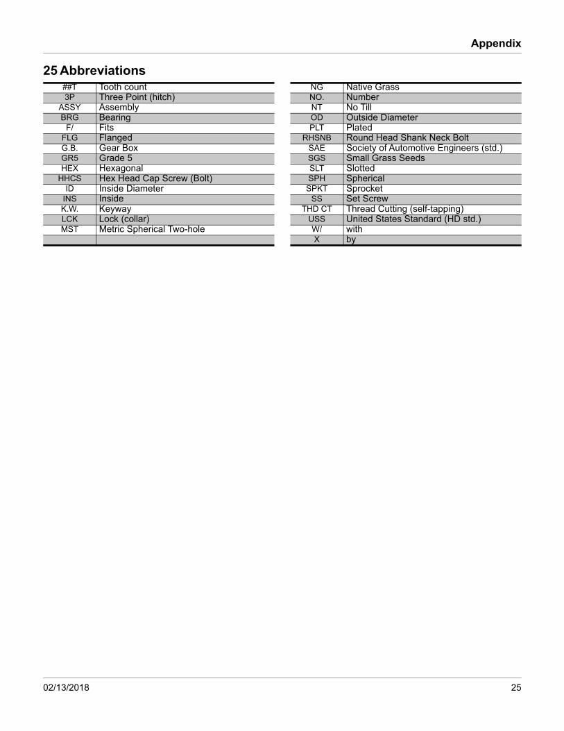
25 Abbreviations##T Tooth count NG Native Grass3P Three Point (hitch) NO. Number
ASSY Assembly NT No TillBRG Bearing OD Outside Diameter
F/ Fits PLT PlatedFLG Flanged RHSNB Round Head Shank Neck BoltG.B. Gear Box SAE Society of Automotive Engineers (std.)GR5 Grade 5 SGS Small Grass SeedsHEX Hexagonal SLT Slotted
HHCS Hex Head Cap Screw (Bolt) SPH SphericalID Inside Diameter SPKT Sprocket
INS Inside SS Set ScrewK.W. Keyway THD CT Thread Cutting (self-tapping)LCK Lock (collar) USS United States Standard (HD std.)MST Metric Spherical Two-hole W/ with
X by
02/13/2018 25

Installation Manual Template
26 Torque Values
94 6
BoltSize
Bolt Head IdentificationBoltSize
Bolt Head Identification
Grade 2 Grade 5 Grade 8 Class 5.8 Class 8.8 Class 10.9in-tpia N-mb N-m N-m mm x pitchc N-m N-m N-m1
4-20 7.4 11 M 5 X 0.81
4-28 8.5 13 18 M 6 X 1 7 11 155
16-18 15 24 33 M 8 X 1.25 17 26 365
16-24 17 26 37 M 8 X 1 18 28 393
8-16 27 42 59 M10 X 1.5 33 52 723
8-24 31 47 67 M10 X 0.75 39 61 857
16-14 43 67 95 M12 X 1.75 58 91 1257
16-20 49 75 105 M12 X 1.5 60 95 1301
2-13 66 105 145 M12 X 1 90 105 1451
2-20 75 115 165 M14 X 2 92 145 2009
16-12 95 150 210 M14 X 1.5 99 155 2159
16-18 105 165 235 M16 X 2 145 225 3155
8-11 130 205 285 M16 X 1.5 155 240 3355
8-18 150 230 325 M18 X 2.5 195 310 4053
4-10 235 360 510 M18 X 1.5 220 350 4853
4-16 260 405 570 M20 X 2.5 280 440 6107
8-9 225 585 820 M20 X 1.5 310 650 9007
8-14 250 640 905 M24 X 3 480 760 1050
1-8 340 875 1230 M24 X 2 525 830 1150
1-12 370 955 1350 M30 X 3.5 960 1510 2100
118-7 480 1080 1750 M30 X 2 1060 1680 2320
118-12 540 1210 1960 M36 X 3.5 1730 2650 3660
114-7 680 1520 2460 M36 X 2 1880 2960 4100
114-12 750 1680 2730
138-6 890 1990 3230 a. in-tpi = nominal thread diameter in inches-threads per inch
138-12 1010 2270 3680 b. N· m = newton-meters
112-6 1180 2640 4290 c. mm x pitch = nominal thread diameter in mm x thread pitch
5.8 8.8 10.9
ft-lbd ft-lb ft-lb ft-lb ft-lb ft-lb5.6 8 12
6 10 14 5 8 11
11 17 25 12 19 27
13 19 27 13 21 29
20 31 44 24 39 53
22 35 49 29 45 62
32 49 70 42 67 93
36 55 78 44 70 97
49 76 105 66 77 105
55 85 120 68 105 150
70 110 155 73 115 160
79 120 170 105 165 230
97 150 210 115 180 245
110 170 240 145 230 300
170 265 375 165 260 355
190 295 420 205 325 450
165 430 605 230 480 665
185 475 670 355 560 780
250 645 910 390 610 845
275 705 995 705 1120 1550
355 795 1290 785 1240 1710
395 890 1440 1270 1950 2700
500 1120 1820 1380 2190 3220
555 1240 2010
655 1470 2380
745 1670 2710
870 1950 3160
3 5 7
26 Great Plains | 133-140M


Great Plains, Mfg.1525 E. North St.P.O. Box 5060Salina, KS 67402