installation instructions for ewd13 and ewf13 … instructions for ewd13 and ewf13 sprocket box...
TRANSCRIPT
© Copyright 2016 Printed 10/13/16 152-208M
Installation Instructions forEWD13 and EWF13 Sprocket Box Update
Before Getting Started
Before you begin installation of your Sprocket Box Update, read these instructions carefully and check that all parts and tools in kit are accounted for. All hand and specialty tools for installation are provided at owner’s expense. Please retain these installation instructions for future reference and parts ordering information.
These installation instructions contain information for assembling the Sprocket Box Update to the main machine. Please read all instructions in your EWD13 and EWF13 operator manual thoroughly before proceeding. Your operator manual includes information on operation, adjustment, troubleshooting, and maintenance for this attachment (some manual sections do not apply to all accessories).
See page 8 and page 9 of these instructions to adjust the seeding rate with the new sprocket box. These instructions replace the "Seed Calibration" section in the operator’s manual originally provided with your drill. As reference, save page 8 and page 9 of these instructions with your operator’s manual. A copy of the updated parts manual is available through your Great Plains dealer.
General Information
These instructions explain how to install and adjust the sprocket- box update. The sprocket box replaces the original gearbox on Great Plains end-wheel drills. This modification improves the performance and reliability of the original equipment.
Refer to page 3 for a detailed list of parts included in these kits. Use these lists to inventory parts received.
Tools RequiredThe following tools are required for installation:
• General hand tools
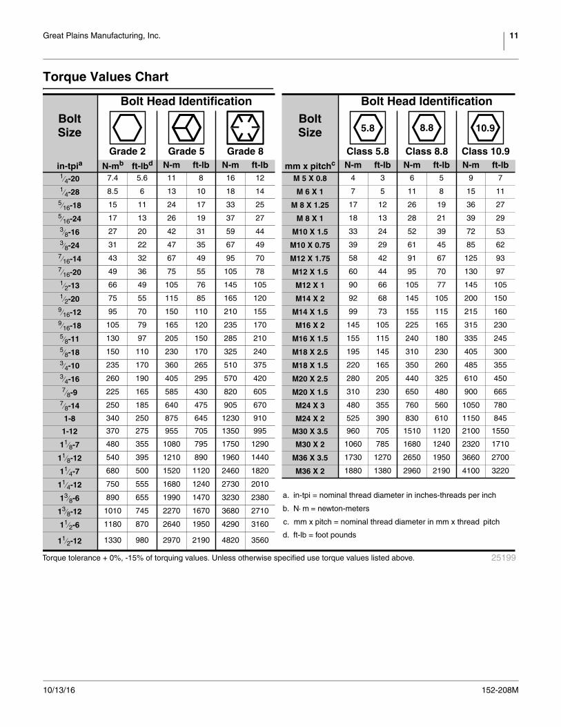
Refer to page 11 for torque values chart.
Document Family
All manuals related to this kit are available free of charge by visiting www.greatplainsag.com. Have machine model and serial numbers available when looking for the manual you need.
Using This Manual
This manual was written to help you install and prepare your new kit. The manual includes instructions for installation and setup. Read this manual and follow the recommendations for safe, efficient, and proper assembly and setup.
Refer to the drill operator’s manual for detailed information on safely operating, adjusting, troubleshooting and maintaining the drill. Refer to the drill parts manual for part identification.
The information in this manual is current at printing. Some parts may change to assure top performance.
Use this kit only in conjunction with a Great Plains implement.
Sprocket Box Update Reference Number
13-Foot EW Sprocket Box Update 152-207A
175-083M 13-Foot EW Drill Operator’s Manual
175-083P 13-Foot EW Parts Manual

2 Sprocket Box Update Great Plains Manufacturing, Inc.
152-208M 10/13/16
Safety & Symbol Information
When you see this symbol, the subsequent instructions and warnings are serious - follow without exception. Your life and the lives of others depend on it!
A crucial point of information related to the current topic. Read and follow the directions to remain safe, avoid serious damage to equipment and ensure desired field results.
Call-Outs
Be Aware of Signal Words
The following signal words designate a degree or level of hazard seriousness. Take the necessary precautions and exercise sound judgment.
DANGER indicates an imminently hazardous situation which, if not avoided, will result in death or serious injury. This signal word is limited to the most extreme situations, typically for machine components that, for functional purposes, cannot be guarded.
WARNING indicates a potentially hazardous situation which, if not avoided, could result in death or serious injury, and includes hazards that are exposed when guards are removed. It may also be used to alert against unsafe practices.
CAUTION indicates a potentially hazardous situation which, if not avoided, may result in minor or moderate injury. It may also be used to alert against unsafe practices.
Further Assistance
Great Plains Manufacturing, Inc. wants you to be satisfied with your new Implement Type. If for any reason you do not understand any part of this manual or are otherwise dissatisfied with the product please contact:
Great Plains Service Department1525 E. North St.
P.O. Box 5060Salina, KS 67402-5060
Or go to www.greatplainsag.com and follow the contact information at the bottom of your screen for our service department.
to Single-digit callouts identify components in the currently referenced Figure.
and up Two-digit callouts in the range 11 to 15 reference new parts from the list on <add page #>.
Right-hand and left-hand as used in this manual are determined by facing the direction the machine will travel. An orientation rose in some line art illustrations shows the directions of: Up, Back, Left, Down, Front, Right.
U
DF
B
L
R
1 9
11
Great Plains Manufacturing, Inc. 3
10/13/16 152-208M
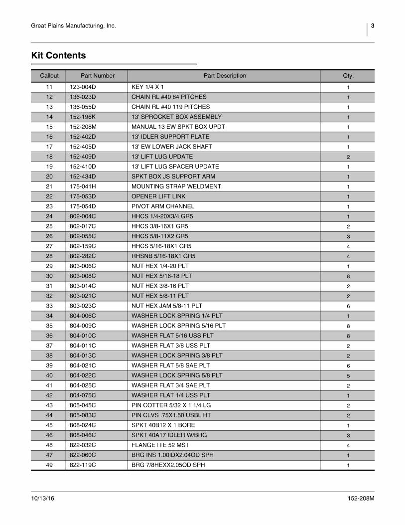
Kit Contents
Callout Part Number Part Description Qty.
11 123-004D KEY 1/4 X 1 1
12 136-023D CHAIN RL #40 84 PITCHES 1
13 136-055D CHAIN RL #40 119 PITCHES 1
14 152-196K 13' SPROCKET BOX ASSEMBLY 1
15 152-208M MANUAL 13 EW SPKT BOX UPDT 1
16 152-402D 13' IDLER SUPPORT PLATE 1
17 152-405D 13' EW LOWER JACK SHAFT 1
18 152-409D 13' LIFT LUG UPDATE 2
19 152-410D 13' LIFT LUG SPACER UPDATE 1
20 152-434D SPKT BOX JS SUPPORT ARM 1
21 175-041H MOUNTING STRAP WELDMENT 1
22 175-053D OPENER LIFT LINK 1
23 175-054D PIVOT ARM CHANNEL 1
24 802-004C HHCS 1/4-20X3/4 GR5 1
25 802-017C HHCS 3/8-16X1 GR5 2
26 802-055C HHCS 5/8-11X2 GR5 3
27 802-159C HHCS 5/16-18X1 GR5 4
28 802-282C RHSNB 5/16-18X1 GR5 4
29 803-006C NUT HEX 1/4-20 PLT 1
30 803-008C NUT HEX 5/16-18 PLT 8
31 803-014C NUT HEX 3/8-16 PLT 2
32 803-021C NUT HEX 5/8-11 PLT 2
33 803-023C NUT HEX JAM 5/8-11 PLT 6
34 804-006C WASHER LOCK SPRING 1/4 PLT 1
35 804-009C WASHER LOCK SPRING 5/16 PLT 8
36 804-010C WASHER FLAT 5/16 USS PLT 8
37 804-011C WASHER FLAT 3/8 USS PLT 2
38 804-013C WASHER LOCK SPRING 3/8 PLT 2
39 804-021C WASHER FLAT 5/8 SAE PLT 6
40 804-022C WASHER LOCK SPRING 5/8 PLT 5
41 804-025C WASHER FLAT 3/4 SAE PLT 2
42 804-075C WASHER FLAT 1/4 USS PLT 1
43 805-045C PIN COTTER 5/32 X 1 1/4 LG 2
44 805-083C PIN CLVS .75X1.50 USBL HT 2
45 808-024C SPKT 40B12 X 1 BORE 1
46 808-046C SPKT 40A17 IDLER W/BRG 3
48 822-032C FLANGETTE 52 MST 4
47 822-060C BRG INS 1.00IDX2.04OD SPH 1
49 822-119C BRG 7/8HEXX2.05OD SPH 1
4 Sprocket Box Update Great Plains Manufacturing, Inc.
152-208M 10/13/16
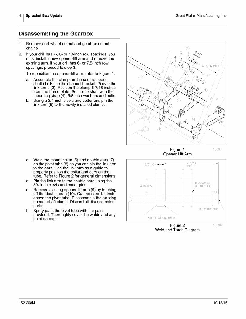
Disassembling the Gearbox
1. Remove end-wheel-output and gearbox-output chains.
2. If your drill has 7-, 8- or 10-inch row spacings, you must install a new opener-lift arm and remove the existing arm. If your drill has 6- or 7.5-inch row spacings, proceed to step 3.
To reposition the opener-lift arm, refer to Figure 1.
a. Assemble the clamp on the square opener shaft (1). Place the channel bracket (2) over the link arms (3). Position the clamp 6 7/16 inches from the frame plate. Secure to shaft with the mounting strap (4), 5/8-inch washers and bolts.
b. Using a 3/4-inch clevis and cotter pin, pin the link arm (5) to the newly installed clamp.
c. Weld the mount collar (6) and double ears (7) on the pivot tube (8) so you can pin the link arm to the ears. Use the link arm as a guide to properly position the collar and ears on the tube. Refer to Figure 2 for general dimensions.
d. Pin the link arm to the double ears using the 3/4-inch clevis and cotter pins.
e. Remove existing opener-lift arm (9) by torching off the double ears (10). Cut the ears 1/4 inch above the pivot tube. Disassemble the existing opener-shaft clamp. Discard all disassembled parts.
f. Spray paint the pivot tube with the paint provided. Thoroughly cover the welds and any paint damage.
Figure 1Opener Lift Arm
16597
Figure 2Weld and Torch Diagram
16598
Great Plains Manufacturing, Inc. 5
10/13/16 152-208M
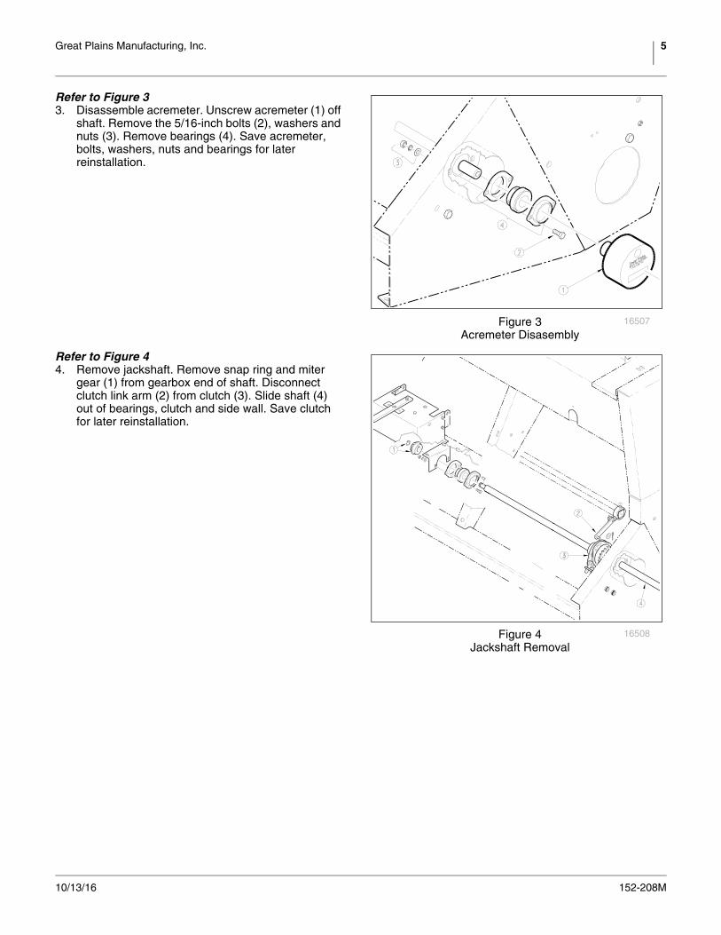
Refer to Figure 33. Disassemble acremeter. Unscrew acremeter (1) off
shaft. Remove the 5/16-inch bolts (2), washers and nuts (3). Remove bearings (4). Save acremeter, bolts, washers, nuts and bearings for later reinstallation.
Refer to Figure 44. Remove jackshaft. Remove snap ring and miter
gear (1) from gearbox end of shaft. Disconnect clutch link arm (2) from clutch (3). Slide shaft (4) out of bearings, clutch and side wall. Save clutch for later reinstallation.
Figure 3Acremeter Disasembly
16507
Figure 4Jackshaft Removal
16508
6 Sprocket Box Update Great Plains Manufacturing, Inc.
152-208M 10/13/16
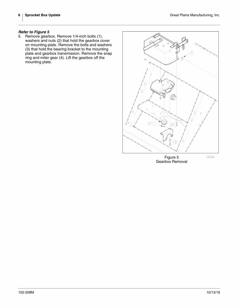
Refer to Figure 55. Remove gearbox. Remove 1/4-inch bolts (1),
washers and nuts (2) that hold the gearbox cover on mounting plate. Remove the bolts and washers (3) that hold the bearing bracket to the mounting plate and gearbox transmission. Remove the snap ring and miter gear (4). Lift the gearbox off the mounting plate.
Figure 5Gearbox Removal
16509

Great Plains Manufacturing, Inc. 7
10/13/16 152-208M
Installing the Sprocket Box
Refer to Figure 6
1. Drill two 13/32-inch holes for idler bracket. First, bolt the idler bracket (1) to the mounting plate (2) using a 1/4-inch bolt (3), washer, lock washer and nut (4) at the location shown. The idler bracket will wrap around the right-hand side of the frame plate (5). Use the two bolt holes (6) in the bracket as a guide for where to drill. When finished drilling, unbolt the idler bracket from the mounting plate.
2. Assemble bearings (7) on the idler bracket using 5/16-inch bolts (8), washers, lock washers and nuts (9).
3. Assemble idlers (10) on idler bracket. Bolt the idlers to the bracket in the order shown (sprocket, 5/8-inch nut, flat washer, bracket, flat washer, lock washer, nut).
4. Mount the idler bracket on the mounting plate and through the frame-plate holes drilled in step 1. Mount the idler bracket to the frame plate using 3/8-inch bolts (11), washers, lock washers and nuts (12).
5. Install sprocket box. Bolt the box (13) to the mounting plate through four holes using 5/16-inch bolts (14), washers, lock washers and nuts (15).
6. Install new jackshaft. Slide jackshaft (16) through side wall and clutch, under mounting plate and through idler bracket. Install the 12-tooth sprocket (17) on the end of the shaft and secure with the 1/4-inch key (18).
7. Route 119-pitch chain (19) over sprocket-box input and idlers as shown. Route 84-pitch chain (20) over gearbox output, idler and seed-cup-shaft input as shown.
8. Reconnect clutch-link arm and reinstall gauge-wheel-to-jackshaft chain. Reassemble acremeter.
Figure 6Idler Plate and Gearbox Installation
16514
8 Sprocket Box Update Great Plains Manufacturing, Inc.
152-208M 10/13/16
Seeding Adjustment
Calibrating the seeding rate requires four steps: arranging the drive sprockets, setting the seed-rate handle, positioning the seed-cup doors, and checking the seeding rate.
Refer to the seed-rate charts. These charts list the proper sprocket sizes and seed-rate-handle settings for various seeds and seeding rates.
The seed-rate charts are based on cleaned, untreated seed of average size and test weight. The charts are based on 9.5 x 20 rib implement tires. Many factors will affect seeding rates including foreign material, seed treatment, seed size, field conditions, tire pressure and test weight. You likely will need to make minor adjustments. Set and check the seeding rate using the procedures below, then re-adjust the rate as necessary.
Note: A pea-drive adaptor kit is available for the 13-foot end-wheel drill. Different seed-rate charts are included in the pea-drive kit.
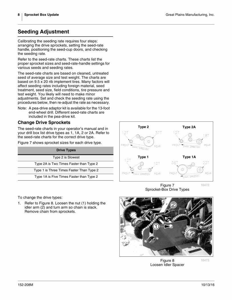
Change Drive SprocketsThe seed-rate charts in your operator’s manual and in your drill box list drive types as 1, 1A, 2 or 2A. Refer to the seed-rate charts for the correct drive type.
Figure 7 shows sprocket sizes for each drive type.
To change the drive types:
1. Refer to Figure 8. Loosen the nut (1) holding the idler arm (2) and turn arm so chain is slack. Remove chain from sprockets.
Drive Types
Type 2 is Slowest
Type 2A is Two Times Faster than Type 2
Type 1 is Three Times Faster Than Type 2
Type 1A is Five Times Faster than Type 2
Type 2A
Type 1 Type 1A
Type 2
Figure 7Sprocket-Box Drive Types
16472
1
2
Figure 8Loosen Idler Spacer
16473
Great Plains Manufacturing, Inc. 9
10/13/16 152-208M
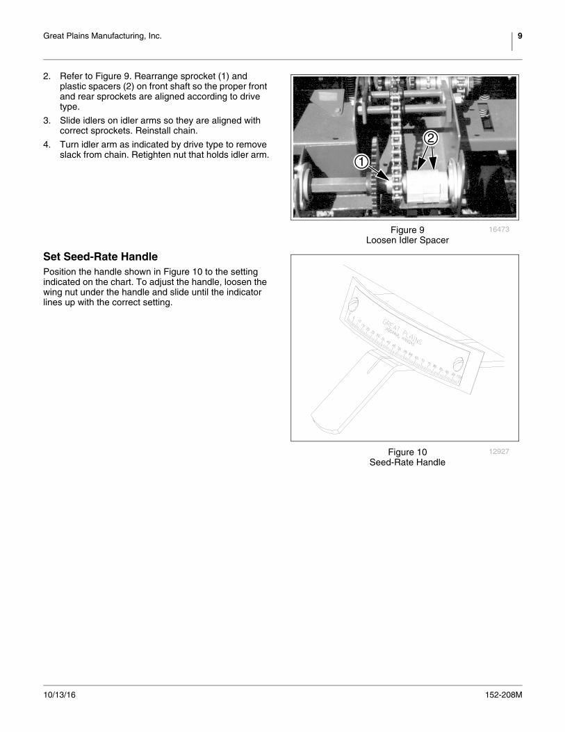
2. Refer to Figure 9. Rearrange sprocket (1) and plastic spacers (2) on front shaft so the proper front and rear sprockets are aligned according to drive type.
3. Slide idlers on idler arms so they are aligned with correct sprockets. Reinstall chain.
4. Turn idler arm as indicated by drive type to remove slack from chain. Retighten nut that holds idler arm.
Set Seed-Rate HandlePosition the handle shown in Figure 10 to the setting indicated on the chart. To adjust the handle, loosen the wing nut under the handle and slide until the indicator lines up with the correct setting.
1
2
Figure 9Loosen Idler Spacer
16473
Figure 10Seed-Rate Handle
12927
10 Sprocket Box Update Great Plains Manufacturing, Inc.
152-208M 10/13/16
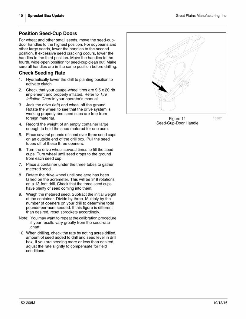
Position Seed-Cup DoorsFor wheat and other small seeds, move the seed-cup-door handles to the highest position. For soybeans and other large seeds, lower the handles to the second position. If excessive seed cracking occurs, lower the handles to the third position. Move the handles to the fourth, wide-open position for seed-cup clean out. Make sure all handles are in the same position before drilling.
Check Seeding Rate1. Hydraulically lower the drill to planting position to
activate clutch.
2. Check that your gauge-wheel tires are 9.5 x 20 rib implement and properly inflated. Refer to Tire Inflation Chart in your operator’s manual.
3. Jack the drive (left) end wheel off the ground. Rotate the wheel to see that the drive system is working properly and seed cups are free from foreign material.
4. Record the weight of an empty container large enough to hold the seed metered for one acre.
5. Place several pounds of seed over three seed cups on an outside end of the drill box. Pull the seed tubes off of these three openers.
6. Turn the drive wheel several times to fill the seed cups. Turn wheel until seed drops to the ground from each seed cup.
7. Place a container under the three tubes to gather metered seed.
8. Rotate the drive wheel until one acre has been tallied on the acremeter. This will be 348 rotations on a 13-foot drill. Check that the three seed cups have plenty of seed coming into them.
9. Weigh the metered seed. Subtract the initial weight of the container. Divide by three. Multiply by the number of openers on your drill to determine total pounds-per-acre seeded. If this figure is different than desired, reset sprockets accordingly.
Note: You may want to repeat the calibration procedure if your results vary greatly from the seed-rate chart.
10. When drilling, check the rate by noting acres drilled, amount of seed added to drill and seed level in drill box. If you are seeding more or less than desired, adjust the rate slightly to compensate for field conditions.
Figure 11Seed-Cup-Door Handle
13867
Great Plains Manufacturing, Inc. 11
10/13/16 152-208M
Torque Values Chart
94 6
25199m
BoltSize
Bolt Head IdentificationBoltSize
Bolt Head Identification
Grade 2 Grade 5 Grade 8 Class 5.8 Class 8.8 Class 10.9in-tpia N-mb N-m N-m mm x pitchc N-m N-m N-m1
4-20 7.4 11 M 5 X 0.81
4-28 8.5 13 18 M 6 X 1 7 11 155
16-18 15 24 33 M 8 X 1.25 17 26 365
16-24 17 26 37 M 8 X 1 18 28 393
8-16 27 42 59 M10 X 1.5 33 52 723
8-24 31 47 67 M10 X 0.75 39 61 857
16-14 43 67 95 M12 X 1.75 58 91 1257
16-20 49 75 105 M12 X 1.5 60 95 1301
2-13 66 105 145 M12 X 1 90 105 1451
2-20 75 115 165 M14 X 2 92 145 2009
16-12 95 150 210 M14 X 1.5 99 155 2159
16-18 105 165 235 M16 X 2 145 225 3155
8-11 130 205 285 M16 X 1.5 155 240 3355
8-18 150 230 325 M18 X 2.5 195 310 4053
4-10 235 360 510 M18 X 1.5 220 350 4853
4-16 260 405 570 M20 X 2.5 280 440 6107
8-9 225 585 820 M20 X 1.5 310 650 9007
8-14 250 640 905 M24 X 3 480 760 1050
1-8 340 875 1230 M24 X 2 525 830 1150
1-12 370 955 1350 M30 X 3.5 960 1510 2100
118-7 480 1080 1750 M30 X 2 1060 1680 2320
118-12 540 1210 1960 M36 X 3.5 1730 2650 3660
114-7 680 1520 2460 M36 X 2 1880 2960 4100
114-12 750 1680 2730
138-6 890 1990 3230 a. in-tpi = nominal thread diameter in inches-threads per inch
138-12 1010 2270 3680 b. N· m = newton-meters
112-6 1180 2640 4290
112-12 1330 2970 4820
c. mm x pitch = nominal thread diameter in mm x thread pitch
Torque tolerance + 0%, -15% of torquing values. Unless otherwise specified use torque values listed above.
5.8 8.8 10.9
25199
ft-lbd ft-lb ft-lb ft-lb ft-lb ft-lb5.6 8 12
6 10 14 5 8 11
11 17 25 12 19 27
13 19 27 13 21 29
20 31 44 24 39 53
22 35 49 29 45 62
32 49 70 42 67 93
36 55 78 44 70 97
49 76 105 66 77 105
55 85 120 68 105 150
70 110 155 73 115 160
79 120 170 105 165 230
97 150 210 115 180 245
110 170 240 145 230 300
170 265 375 165 260 355
190 295 420 205 325 450
165 430 605 230 480 665
185 475 670 355 560 780
250 645 910 390 610 845
275 705 995 705 1120 1550
355 795 1290 785 1240 1710
395 890 1440 1270 1950 2700
500 1120 1820 1380 2190 3220
555 1240 2010
655 1470 2380
745 1670 2710
870 1950 3160d. ft-lb = foot pounds
980 2190 3560
3 5 7

12 Sprocket Box Update Great Plains Manufacturing, Inc.
152-208M 10/13/16


Great Plains, Mfg.1525 E. North St.P.O. Box 5060Salina, KS 67402