installation instructions for 99-7014 - metra online · instrucciones de instalación para 99-7014...
TRANSCRIPT

APPLICATIONS
METRA. The World’s best kits.™ metraonline.com1-800-221-0932 © COPYRIGHT 2004-2013 METRA ELECTRONICS CORPORATION
REV.
12/
15/2
013
INS
T99-
7014
CAUTION: Metra recommends disconnecting the negative battery terminal before beginning any installation. All accessories, switches, and especially air bag indicator lights must be plugged in before reconnecting the battery or cycling the ignition.
NOTE: Refer to the instructions included with the aftermarket radio.
Installation instructions for 99-7014
• ISODINradioprovisionwithpocket• DoubleDINradioprovision• 99-7014B - Painted scratch resistant matte black• 99-7014HG - Painted high gloss black
•A)Radiotrimplate•B)Hazardcontrolboard•C)DoubleDINbrackets•D)Pocket•E)(9)Panelclips•F)(7)#8x3/8”Phillipspanheadscrews•G)(4)#8x3/8”Phillipstrussheadscrews •H)(3)#4x3/8”Phillipspanheadscrews
KIT FEATURES
KIT COMPONENTS
WIRING & ANTENNA CONNECTIONS(soldseparately)
WiringHarness:•70-7005-Mitsubishiharness2007-up•MITO-02-(2011-2013models)•MITO-03-(2014models)
AntennaAdapter:•Notrequired
•Panelremovaltool•Phillipsscrewdriver•Socketset
TOOLS REQUIRED
Mitsubishi Outlander Sport 2011-201499-7014
See application list inside
A B C D E
F G H

99-7014
2
Dash Disassembly
– MitsubishiOutlanderSport2011-2014...........................................................2-4
Kit Assembly
– Radiotrimpanelassembly................................................................................. 5
– ISODINradioprovisionwithpocket.................................................................... 6
– DoubleDINradioprovision................................................................................. 7
Table of Contents1. Gentlyprytheradiocontrol
panelfromthedash.Disconnecttheharnessandplacepanelaside.(FigureA)
2. Remove(4)Phillipsscrewssecuringtheradiochassistothesubdashandremoveradio.(FigureB)
Continued on next page
Mitsubishi Outlander Sport 2011-2014
(Figure B)
(Figure A)
3
Dash Disassembly 99-7014
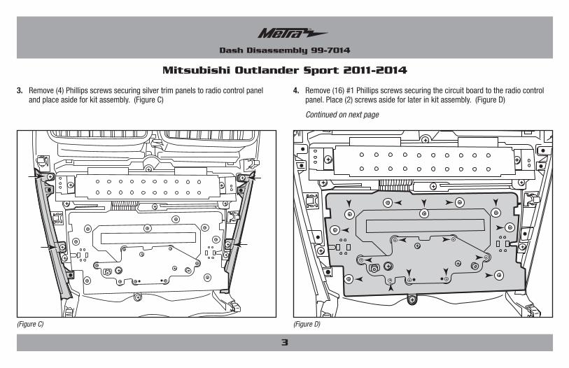
3. Remove(4)Phillipsscrewssecuringsilvertrimpanelstoradiocontrolpanelandplaceasideforkitassembly.(FigureC)
4. Remove(16)#1Phillipsscrewssecuringthecircuitboardtotheradiocontrolpanel.Place(2)screwsasideforlaterinkitassembly.(FigureD)
Continued on next page
Mitsubishi Outlander Sport 2011-2014
(Figure C) (Figure D)

4
Dash Disassembly 99-7014
5. Remove(11)#2Phillipsscrewssecuringthecircuitboardtotheradiocontrolpanel.Removethecircuitboardfromtheradiocontrolpanel.(FigureE)
6. Removethehazardbuttonfromtheradiocontrolpanel.Placehazardbuttonasideforkitassembly.(FigureF)
Mitsubishi Outlander Sport 2011-2014
(Figure D) (Figure F)
7. Remove(3)#2PhillipsscrewsfromtheLCDfilterpanel.Unclipventsandplaceasideforkitassembly.(FigureG)
8. Removefactoryairbagandseatbeltlabelsfromfactorypanelandplaceasideforkitassembly.
Continue to kit assembly(Figure F)

5
Kit Assembly 99-7014
Radio trim panel assembly
1. Installpanelclipsonradiotrimpanel.(FigureA)
2. Clipfactoryventsremovedearlierintoradiotrimpanel.(FigureA)
3. Securesilvertrimpanelstoradiotrimpanelwith(4)included#83/8”Phillipspanheadscrews.(FigureA)
(Figure A)
4. Securefactoryhazardbuttontoradiotrimpanelwith(3)included#83/8”Phillipspanheadscrews.(FigureB)
5. Securecircuitboardtofactoryhazardbuttonwith(2)Phillipsscrewsremovedearlier.(FigureC)
6. Continuesecuringthecircuitboardtoradiotrimpanelwith(3)included#43/8”Phillipspanheadscrews.(FigureD)
7. Placeairbagandseatbeltlabelsremovedearlieronradiotrimpanel.
Continued on next page
(Figure D)(Figure B)
(Figure C)
(1) Panel clip locations (2)
(1) Panel clip locations
(3)
6
Dash Disassembly 99-7014
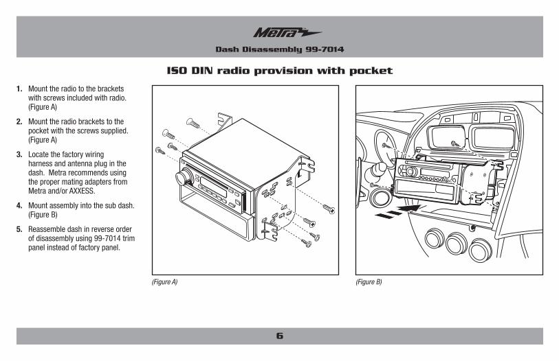
1. Mounttheradiotothebracketswithscrewsincludedwithradio.(FigureA)
2. Mounttheradiobracketstothepocketwiththescrewssupplied.(FigureA)
3. Locatethefactorywiringharnessandantennapluginthedash.MetrarecommendsusingthepropermatingadaptersfromMetraand/orAXXESS.
4. Mountassemblyintothesubdash.(FigureB)
5. Reassembledashinreverseorderofdisassemblyusing99-7014trimpanelinsteadoffactorypanel.
ISO DIN radio provision with pocket
(Figure A) (Figure B)

1. MounttheradiotothedoubleDINbracketswithscrewsincludedwithradio.(FigureA)
2. Locatethefactorywiringharnessandantennapluginthedash.MetrarecommendsusingthepropermatingadaptersfromMetraand/orAXXESS.
3. Mountassemblyintothesubdash.(FigureB)
4. Reassembledashinreverseorderofdisassemblyusing99-7014trimpanelinsteadoffactorypanel.
7
Double DIN radio provision
(Figure A) (Figure B)

METRA. The World’s best kits.™ metraonline.com1-800-221-0932 © COPYRIGHT 2004-2013 METRA ELECTRONICS CORPORATION
REV.
12/
15/2
013
INS
T99-
7014
KNOWLEDGE IS POWEREnhance your installation and fabrication skills by enrolling in the most recognized and respected mobile electronics school in our industry.Log onto www.installerinstitute.com or call 800-354-6782 for more information and take steps toward a better tomorrow.
Metra recommends MECP certified technicians
Installation instructions for 99-7014

APLICACIONES
METRA. The World’s best kits.™ metraonline.com1-800-221-0932 © COPYRIGHT 2004-2013 METRA ELECTRONICS CORPORATION
REV.
12/
15/2
013
INS
T99-
7014
PRECAUCIÓN: Metra recomienda desconectar el terminal negativo de la batería antes de comenzar cualquier instalación. Todos los accesorios, interruptores y, especialmente, las luces indicadoras de airbag deben estar enchufados antes de volver a conectar la batería o comenzar el ciclo de ignición.
NOTA: Remítase a las instrucciones incluidas con el radio de postventa.
Instrucciones de instalación para 99-7014
• ProvisiónderadioISODINconbolsillo• ProvisiónderadiodobleDIN• 99-7014B - Pintada en negro mate• 99-7014HG - Pintada en alto brillo negro
•A)Paneldecorativopararadio•B)Tablerodecontroldepeligros•C)SoportesdobleDIN•D)Bolsillo•E)Sujetadoresdepanel•F)(7)tornillosPhillipsdecabezatroncocónica#8de3/8”•G)(4)tornillosPhillipsdecabezasegmentada#8de3/8”•H)(3)tornillosPhillipsdecabezatroncocónica#4de3/8”
CARACTERÍSTICAS DEL KIT
COMPONENTES DEL KIT
•Herramientaderemocióndepanel•DestornilladorPhillips•Llaveparadados
HERRAMIENTAS REQUERIDAS
Mitsubishi Outlander Sport 2011-201499-7014
Lista de aplicaciones dentroCABLEADO Y CONEXIONES DE ANTENAArnésdecableado:
•70-7005•MITO-02-(2011-2013models)•MITO-03-(2014models)
Adaptadordeantena:•Noserequiere
(sevendenporseparado)
A B C D E
F G H
99-7014
2
Desmontaje del tablero
– MitsubishiOutlanderSport2011-2014...........................................................2-4
Ensamble del kit
– Paneldemoldurapararadioensamble.............................................................. 5
– ProvisiónderadioISODINconbolsillo............................................................... 6
– ProvisiónderadiodobleDIN............................................................................... 7
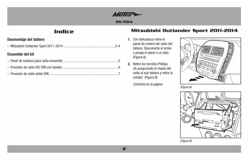
Indice1. Condelicadezaretireel
paneldecontroldelradiodeltablero.Desconecteelarnésypongaelpanelaunlado.(FiguraA)
2. RetirelostornillosPhillips(4)asegurandoelchasisdelradioalsubtableroyretirelaunidad.(FiguraB)
Continúa en la página
Mitsubishi Outlander Sport 2011-2014
(Figura B)
(Figura A)

3
Desmontaje del tablero 99-7014
3. RetirelostornillosPhillips(4)asegurandolospanelesdecorativosplateadosalpaneldecontroldelradioydéjelosaunladoparaelensambledelkit.(FiguraC)
4. RetirelostornillosPhillips#1(16)asegurandoeltablerodecircuitoal paneldecontroldelradio.Dejeaunladolostornillos(2)paraelensambleposteriordelkit.(FiguraD)
Continúa en la página
Mitsubishi Outlander Sport 2011-2014
(Figura C) (Figura D)

4
Desmontaje del tablero 99-7014
5. RetirelostornillosPhillips#2(11)asegurandoeltablerodecircuitoalpaneldecontroldelradio.Retireeltablerodecircuitodelpaneldecontroldelradio.(FiguraE)
6. Retireelbotóndelaslucesintermitentesdelpaneldecontroldelradio.Dejeaunladoelbotóndelaslucesintermitentesparaelensambledelkit.(FiguraF)
Mitsubishi Outlander Sport 2011-2014
(Figura D) (Figura F)
7. RetirelostornillosPhillips#2(3)delpaneldefiltrodeLCD.Quitelasrejillasdeventilaciónydéjelasaunladoparaelensambledelkit.(FiguraG)
8. Retirelasetiquetasde fábricadelabolsadeaireydelcinturóndeseguridaddelpaneldefábricaydéjelasaunladoparaelensambledelkit.
Continúe al ensamble del kit (Figura F)

5
Ensamble del kit 99-7014
Panel de moldura para radio ensamble
1. Instalelossujetadoresdelpanelenelpaneldecorativodelradio.(FiguraA)2. Sujetelasrejillasdeventilaciónqueseretiraronpreviamentealpanel
decorativo.(FiguraA)3. Asegurelospanelesdecorativosplateadosalpaneldecorativodelradioconlos
tornillosdecabezatroncocónicaPhillips(4)#8de3/8”incluidos.(FiguraA)
(Figura A)
4. AsegureelbotóndelaslucesintermitentesdefábricaalpaneldecorativoderadioconlostornillosdecabezatroncocónicaPhillips(3)#83/8”incluidos.(FiguraB)
5. AsegureeltablerodecircuitoalbotóndelaslucesintermitentesdefábricaconlostornillosPhillips(2)retiradospreviamente.(FiguraC)
6. ContinúeasegurandoeltablerodecircuitoalpaneldecorativodelradioconlostornillosdecabezasegmentadaPhillips(3)#4de3/8”incluidos.(FiguraD)
7. Coloquelasetiquetasdelabolsadeaireydeloscinturonesdeseguridadretiradasanteriormenteenelpaneldecorativodelradio.
Continúa en la página
(Figura D)(Figura B)
(Figura C)
(1) Ubicaciones los sujetadores del panel (2)
(1) Ubicaciones los sujetadores del panel
(3)
6
Desmontaje del tablero 99-7014
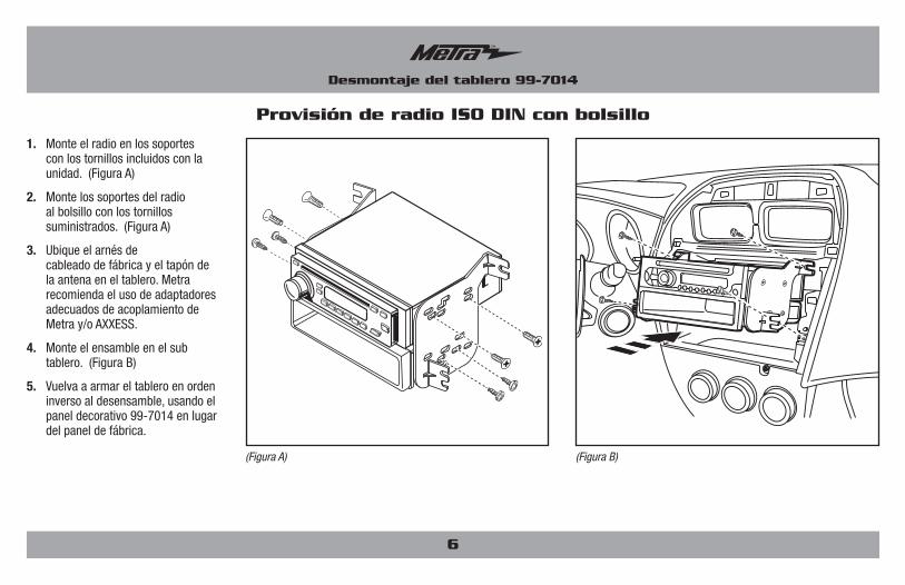
1. Monteelradioenlossoportesconlostornillosincluidosconlaunidad.(FiguraA)
2. Montelossoportesdelradioalbolsilloconlostornillossuministrados.(FiguraA)
3. Ubiqueelarnésdecableadodefábricayeltapóndelaantenaeneltablero.MetrarecomiendaelusodeadaptadoresadecuadosdeacoplamientodeMetray/oAXXESS.
4. Monteelensambleenelsubtablero.(FiguraB)
5. Vuelvaaarmareltableroenordeninversoaldesensamble,usandoelpaneldecorativo99-7014enlugardelpaneldefábrica.
Provisión de radio ISO DIN con bolsillo
(Figura A) (Figura B)

1. MonteelradioenlossoportesdobleDINconlostornillosincluidosconlaunidad.(FiguraA)
2. Ubiqueelarnésdecableadodefábricayeltapóndelaantenaeneltablero.MetrarecomiendaelusodeadaptadoresadecuadosdeacoplamientodeMetray/oAXXESS.
3. Monteelensambleenelsubtablero.(FiguraB)
4. Vuelvaaarmareltableroenordeninversoaldesensamble,usandoelpaneldecorativo99-7014enlugardelpaneldefábrica.
7
Provisión de radio doble DIN
(Figura A) (Figura B)

METRA. The World’s best kits.™ metraonline.com1-800-221-0932 © COPYRIGHT 2004-2013 METRA ELECTRONICS CORPORATION
REV.
12/
15/2
013
INS
T99-
7014
KNOWLEDGE IS POWEREnhance your installation and fabrication skills by enrolling in the most recognized and respected mobile electronics school in our industry.Log onto www.installerinstitute.com or call 800-354-6782 for more information and take steps toward a better tomorrow.
Metra recomienda técnicos con certificación del Programa de Certificación en Electrónica Móvil (Mobile Electronics Certification Program, MECP).
EL CONOCIMIENTO ES PODERMejoresushabilidadesdeinstalaciónyfabricacióninscribiéndoseenlaescueladedispositivoselectrónicosmóvilesmásreconocidayrespetadadenuestraindustria.Regístreseenwww.installerinstitute.comollameal800-354-6782paraobtenermásinformaciónyavancehaciaunfuturomejor.
Instrucciones de instalación para 99-7014