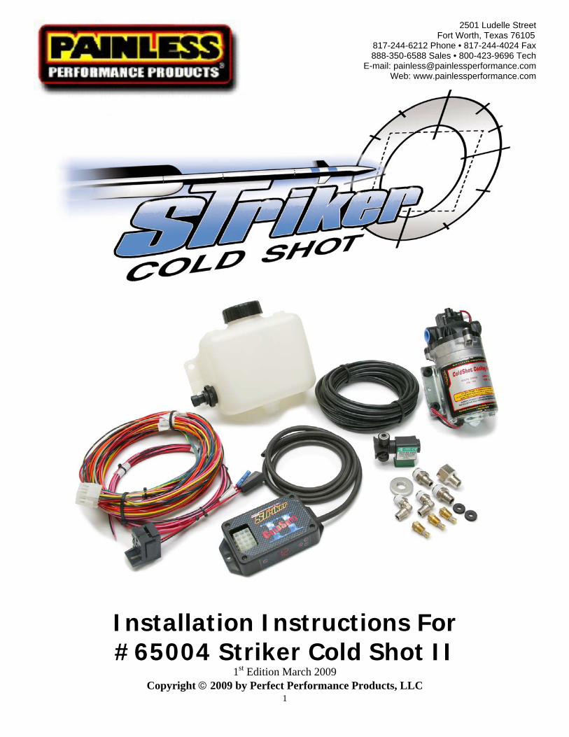
installation instructions for #65004 striker cold shot ii
TRANSCRIPT
1
2501 Ludelle Street Fort Worth, Texas 76105
817-244-6212 Phone • 817-244-4024 Fax 888-350-6588 Sales • 800-423-9696 Tech
E-mail: [email protected] Web: www.painlessperformance.com
Installation Instructions For #65004 Striker Cold Shot II
1st Edition March 2009 Copyright © 2009 by Perfect Performance Products, LLC
2
The 65004 Striker ColdShot II water/methanol injection system is designed to maximize performance out of forced induction engines. After installation; timing, air/fuel ratios and boost settings will need to be modified. Forced induction engine performance is hindered by high intake, combustion chamber and exhaust air temperatures. Premature turbo charger failure is directly related to high exhaust air temperatures; the hotter the exhaust, the shorter lifespan of the turbo charger. The debilitating effects of high intake and exhaust air temperatures are overcome by injecting a water/methanol solution into the post intercooler intake plenum. Lower your engines’ intake, combustion and exhaust temperatures by injecting water/methanol using the Striker ColdShot. After injection, evaporation of the water and methanol absorbs energy in the form of heat from the post intercooler intake air. Cooling of the intake
air temperature produces an air charge more dense with oxygen. Evaporated methanol, a 106 octane fuel, enters the combustion chamber and increases the octane of the combustible fuel. Residual water/methanol droplets also enter the combustion chamber. These droplets absorb heat from the cylinder walls, pistons and heads. At ignition, evaporation/burn of the water/methanol finishes. More heat is absorbed with a resultant of lower combustion and exhaust temperatures.
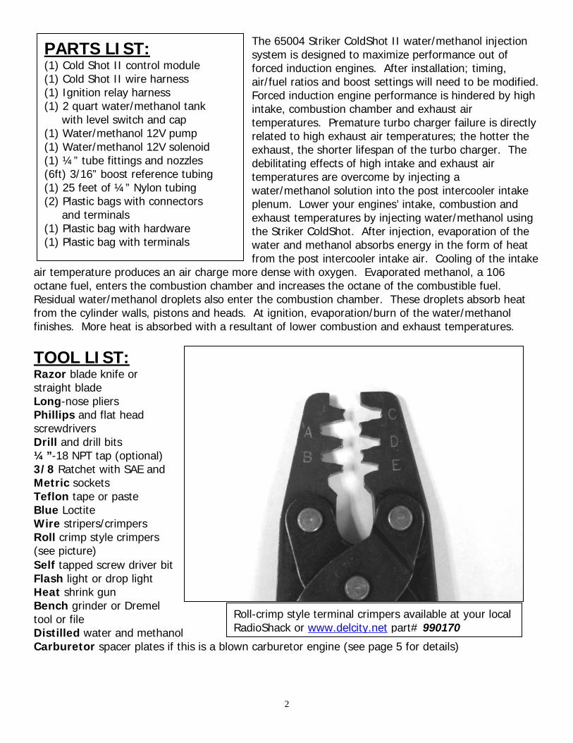
TOOL LIST: Razor blade knife or straight blade Long-nose pliers Phillips and flat head screwdrivers Drill and drill bits ¼”-18 NPT tap (optional) 3/8 Ratchet with SAE and Metric sockets Teflon tape or paste Blue Loctite Wire stripers/crimpers Roll crimp style crimpers (see picture)
Self tapped screw driver bit Flash light or drop light Heat shrink gun Bench grinder or Dremel tool or file Distilled water and methanol Carburetor spacer plates if this is a blown carburetor engine (see page 5 for details)
PARTS LIST: (1) Cold Shot II control module (1) Cold Shot II wire harness (1) Ignition relay harness (1) 2 quart water/methanol tank with level switch and cap (1) Water/methanol 12V pump (1) Water/methanol 12V solenoid (1) ¼” tube fittings and nozzles (6ft) 3/16” boost reference tubing (1) 25 feet of ¼” Nylon tubing (2) Plastic bags with connectors and terminals (1) Plastic bag with hardware (1) Plastic bag with terminals
Roll-crimp style terminal crimpers available at your local RadioShack or www.delcity.net part# 990170
3
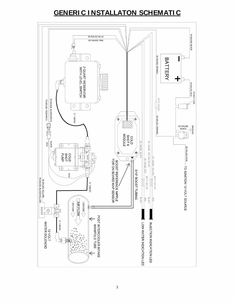
GENERIC INSTALLATON SCHEMATIC
4
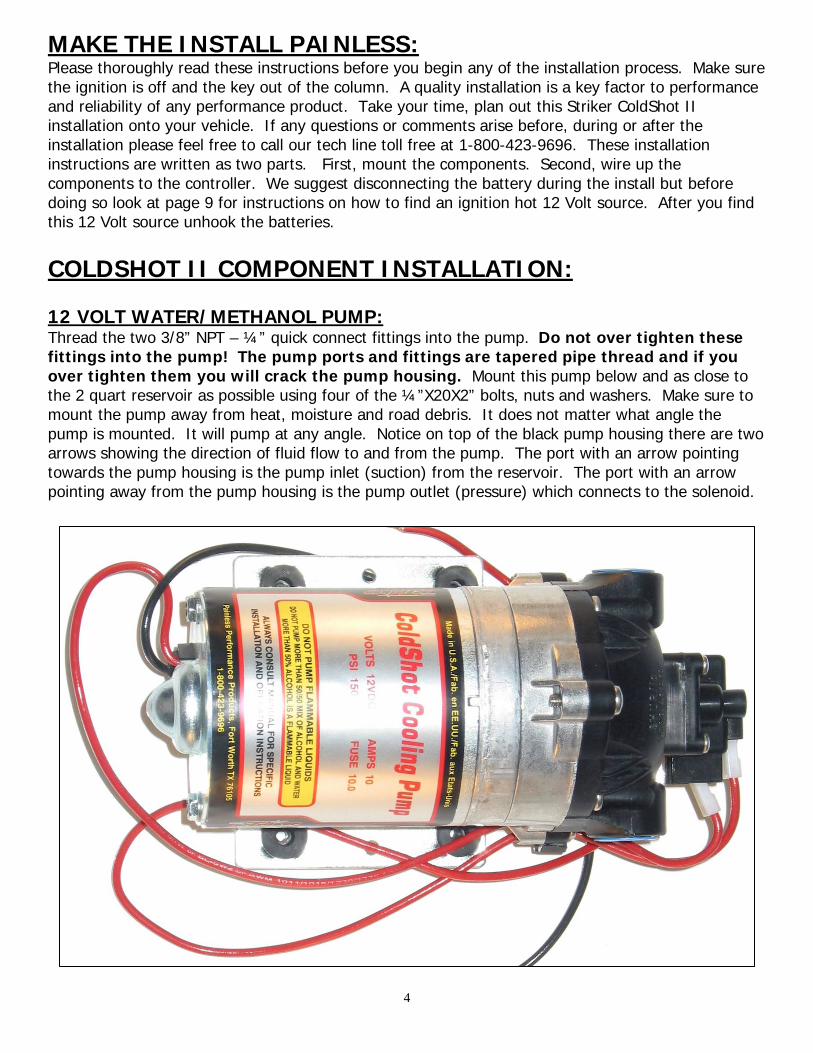
MAKE THE INSTALL PAINLESS: Please thoroughly read these instructions before you begin any of the installation process. Make sure the ignition is off and the key out of the column. A quality installation is a key factor to performance and reliability of any performance product. Take your time, plan out this Striker ColdShot II installation onto your vehicle. If any questions or comments arise before, during or after the installation please feel free to call our tech line toll free at 1-800-423-9696. These installation instructions are written as two parts. First, mount the components. Second, wire up the components to the controller. We suggest disconnecting the battery during the install but before doing so look at page 9 for instructions on how to find an ignition hot 12 Volt source. After you find this 12 Volt source unhook the batteries. COLDSHOT II COMPONENT INSTALLATION: 12 VOLT WATER/METHANOL PUMP: Thread the two 3/8” NPT – ¼” quick connect fittings into the pump. Do not over tighten these fittings into the pump! The pump ports and fittings are tapered pipe thread and if you over tighten them you will crack the pump housing. Mount this pump below and as close to the 2 quart reservoir as possible using four of the ¼”X20X2” bolts, nuts and washers. Make sure to mount the pump away from heat, moisture and road debris. It does not matter what angle the pump is mounted. It will pump at any angle. Notice on top of the black pump housing there are two arrows showing the direction of fluid flow to and from the pump. The port with an arrow pointing towards the pump housing is the pump inlet (suction) from the reservoir. The port with an arrow pointing away from the pump housing is the pump outlet (pressure) which connects to the solenoid.

5
NOZZLE SELECTION: You must now select the nozzle for your Cold Shot system. See below for the flow for each nozzle. Nozzle selection is completely dependent on your engines’ needs. Engine size, horsepower, boost pressure, timing, A/F ratio and intake heat will all need to be taken into consideration. We have provided you three different nozzle sizes. The ratings are based on 100psi. Each nozzle is stamped on the hex edge with a label.
After you select the nozzle, unscrew the filter screen from the back of the nozzle. Make sure the spray side of the nozzle is facing towards the floor when you do this because there is a pellet inside the nozzle housing that will fall out. Leave this pellet in the nozzle housing. Put a little blue Loctite on the threads of the filter screen and reinstall it into the nozzle housing. Don’t over tighten this filter screen to the nozzle housing as this will cause reduced flow from the nozzle. BLOWN FUELINJECTION ENGINE INSTALLATION: The nozzle assembly is pictured above/right. We have provided you with an aluminum and steel bushing in the parts kit that you can TIG weld into an aluminum or steel boost tube. This bushing is pre-tapped with ¼” – 18 NPT. Pay close attention when welding the bushing into your boost tube. Pipe thread is directional and the Nozzle Adapter will not thread into the bushing backwards. If you choose to not use the bushing, simply drill a 7/16” hole and tap it ¼”-18NPT where you want to install the nozzle assembly.
BLOWN CARBURETOR ENGINE INSTALLATION: Carburetor spacers are readily available from many online or local retailers. We suggest that you purchase one or two (depending on how many carburetors you have) ¾” or 1” carburetor spacer(s) in order to install this water/methanol nozzle beneath the carburetor and above the blower. If you are running two carburetors, you will need to purchase the #65020 nozzle upgrade kit so you can spray one nozzle under each carburetor. Once you have the carburetor spacer plate(s) purchased, figure out where the nozzle assembly will fit without getting in the way of throttle linkages or fuel lines. Drill the spacer plate with a 7/16” drill and tap it with a ¼”-18NPT tap. Install the nozzle assembly as the second way described on the next page.
NOZZLE GALLONS PER HOUR MW-C 6.4 MW-D 10.0 MW-E 14.5
6
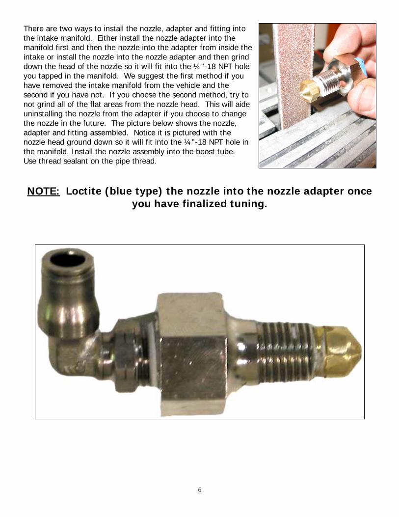
There are two ways to install the nozzle, adapter and fitting into the intake manifold. Either install the nozzle adapter into the manifold first and then the nozzle into the adapter from inside the intake or install the nozzle into the nozzle adapter and then grind down the head of the nozzle so it will fit into the ¼”-18 NPT hole you tapped in the manifold. We suggest the first method if you have removed the intake manifold from the vehicle and the second if you have not. If you choose the second method, try to not grind all of the flat areas from the nozzle head. This will aide uninstalling the nozzle from the adapter if you choose to change the nozzle in the future. The picture below shows the nozzle, adapter and fitting assembled. Notice it is pictured with the nozzle head ground down so it will fit into the ¼”-18 NPT hole in the manifold. Install the nozzle assembly into the boost tube. Use thread sealant on the pipe thread. NOTE: Loctite (blue type) the nozzle into the nozzle adapter once
you have finalized tuning.

7
BOOST REFERENCE TUBING: The ColdShot II module requires a boost reference in order to operate. Included in the parts kit is 8 feet of boost tubing. Push this tubing onto a boost reference fitting of your intake tubing or intake manifold. Make sure to choose a fitting that is not subject to water/methanol penetration. Route the other end of the tubing to where the ColdShot II module is to be mounted. If your intake tubing or manifold does not have a boost/vacuum reference nipple you must install it. Always install the nipple post intercooler. It is advisable to install the nipple directly to the intake manifold on the vacuum side of the throttle body. 12 VOLT SOLENOID: Take the solenoid of the box it was shipped in. The solenoid is marked for the inlet and outlet. See the picture to the right. Both ports are push to connect type fittings. After mounting simply cut the ¼” black tubing with a razor blade and insert it into the solenoid. You will feel a positive stop once the tubing is fully inserted. If you need to pull the tubing out of the solenoid do the following.
• Use the tips of two fingers on one hand to hold the grey collar to the body of the solenoid.
• While holding the grey collar, push the tube towards the solenoid and they pull it out of the port.
Mount the solenoid with two of the supplied self tap screws. It is best to mount the solenoid as close to the nozzle as possible. The top of the solenoid has a threaded nut and bolt that holds the coil to the mechanical base of the solenoid. If you unscrew this nut the coil will come off of the base. This may aide in your mounting of the solenoid. Make sure you reinstall the coil as shown in the above picture. Mount the solenoid in any position that is convenient to you. If the solenoid is mounted upside down, apply a small amount of blue Loctite to the threads of the nut holding the coil. After you have mounted the solenoid, cut a piece of the supplied ¼” tubing to go between the solenoid and the nozzle. Use a razor blade to cut the tubing and make sure to cut it straight with no burrs remaining on the edges. Push the tubing into port 1 on the solenoid and then into nozzle assembly. Next, route the ¼” tubing from the solenoid port 2 to the pump. Insert the tube into the pump outlet; don’t insert this tube into the solenoid yet. This tube needs to be off of the solenoid for the pump to prime itself as discussed on page 11. Make sure to cut the tubing with a razor blade and cut it straight with no burrs on the ends. Use some of the included tie wraps to secure the tubing away from sharp edges, moving parts on the vehicle and anything that gets hot. Use the two ¼” grommets from the parts kit to protect the ¼” tubing from sharp edges if you drill a hole through metal to route it.
8
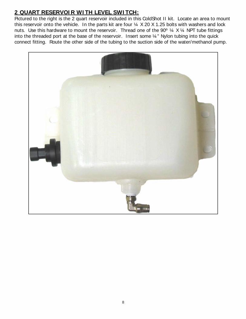
2 QUART RESERVOIR WITH LEVEL SWITCH: Pictured to the right is the 2 quart reservoir included in this ColdShot II kit. Locate an area to mount this reservoir onto the vehicle. In the parts kit are four ¼ X 20 X 1.25 bolts with washers and lock nuts. Use this hardware to mount the reservoir. Thread one of the 90º ¼ X ¼ NPT tube fittings into the threaded port at the base of the reservoir. Insert some ¼” Nylon tubing into the quick connect fitting. Route the other side of the tubing to the suction side of the water/methanol pump.

9
COLDSHOT II ELECTRICAL INSTALLATION: IGNITION RELAY HARNESS: To the right is a picture of the ignition relay harness included in this kit. This relay will supply the 10 Amps of 12 volts needed to power the module and all of its components. You do not have to use this relay harness if you already have an ignition source inside the cab of the vehicle that can supply 10 Amps of fused 12 Volts. If this is the case move on to page 10. First, mount the relay and fuse inside the cab of the vehicle and run the 14 gauge red Battery+ wire out to the engine compartment. Use the supplied self tap screws to drill through and mount the relay to any metal support as pictured to the right. Second, push the relay into the mounting base and the fuse into the fuse holder. Third, connect the wires as listed on the next page.

10
BATTERY+ Connect this wire using one of the supplied ring terminals to the positive post of the battery. GROUND Connect this wire using one of the supplied ring terminals to a good ground. If a chassis ground is used, make sure to scrape the paint from the metal and use a star washer. IGNITION 12 VOLT Connect this wire to an ignition hot 12 Volt source. This wire is only used to activate the ignition relay. Use a multi-meter to identify a key-on 12 Volt source from under the dash or the fuse block. Use one of the supplied Posi-Tap wire taps to connect this wire to another wire. See the picture to the right for instructions on how to use this type of wire tap. Or, use the supplied fuse tap and spade connector if the key-on 12 Volts is sourced from the fuse block.
RELAY OUTPUT This wire will be connected to the wire labeled as Main 12V on the Cold Shot harness. This is the power output wire from the relay harness and will supply key on 12 Volts to the Cold Shot II controller.
11
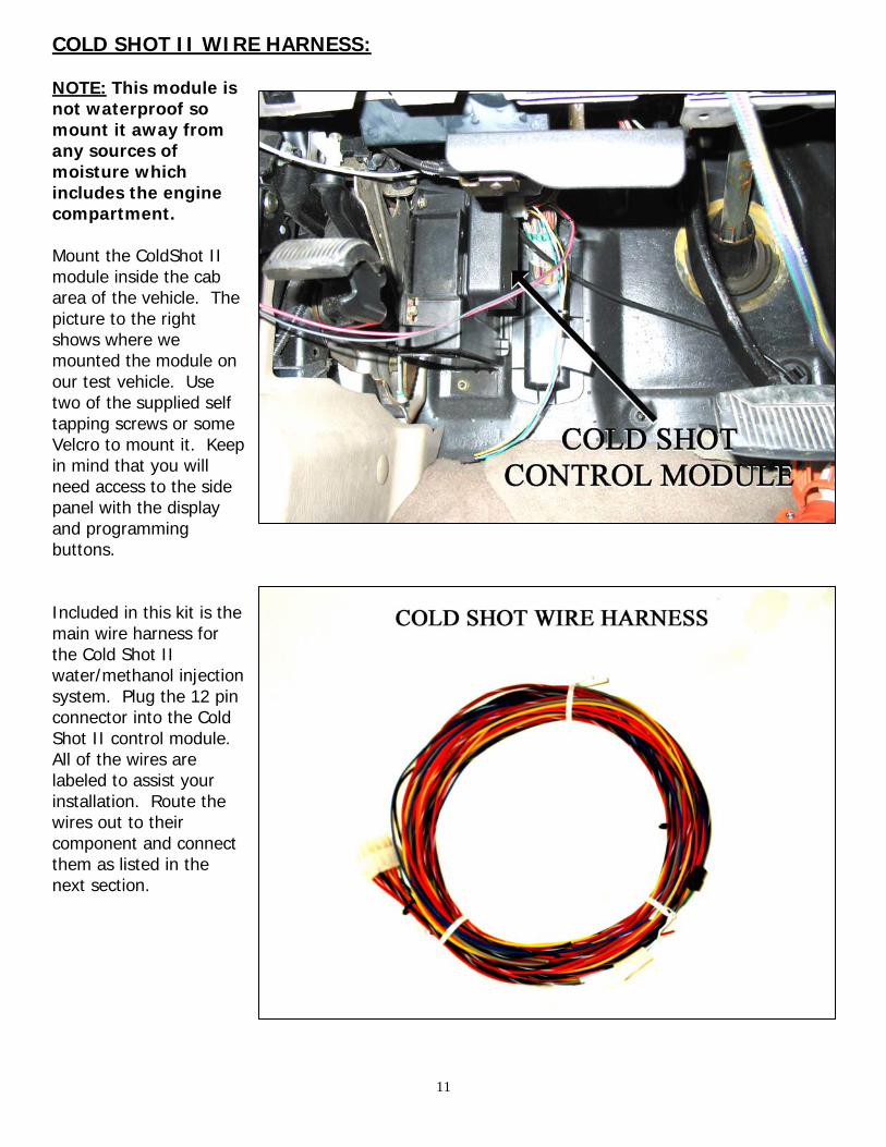
COLD SHOT II WIRE HARNESS: NOTE: This module is not waterproof so mount it away from any sources of moisture which includes the engine compartment. Mount the ColdShot II module inside the cab area of the vehicle. The picture to the right shows where we mounted the module on our test vehicle. Use two of the supplied self tapping screws or some Velcro to mount it. Keep in mind that you will need access to the side panel with the display and programming buttons. Included in this kit is the main wire harness for the Cold Shot II water/methanol injection system. Plug the 12 pin connector into the Cold Shot II control module. All of the wires are labeled to assist your installation. Route the wires out to their component and connect them as listed in the next section.

12
COLDSHOT II MODULE POWER AND GROUND: MAIN 12V- This 14 gauge orange wire connects to the butt splice on the 14 gauge orange wire
labeled Relay Output on the ignition relay harness or to an ignition hot, 10 Amp, 12 Volt source.
MAIN GND- This 14 gauge black wire connects to a chassis ground source. Underneath the dash
there are many good grounding points. You may use one of the already existing dash mounting bolts for this ground or use one of the supplied self tapping screws to create your own grounding point. Check this ground source with a volt meter to make sure you have a good one. Scrape any paint from this grounding point.
WATER/METHANOL PUMP WIRES: Before connecting these you will want to prime the pump. Fill the reservoir with your choice of water/methanol mix. See page 18 for details on which mixture to use and where to purchase it. Make sure the ¼” tube for the inlet of the solenoid is pointing into a catch can of some sort so water/methanol isn’t pumped all over the place. Connect 12 Volt (+) to the red wire and 12 Volt (–) to the black wire. The pump will come on and should prime itself. Take notice the reservoir level should go down. After priming of the pump use the supplied two pin male and female connectors to connect these two wires to the pump. The terminals used for these connectors require the roll crimp style crimpers. See the picture on page 2. These crimpers are available at your local Radio Shack. You do not have to use these connectors to hook up your pump. You can use two of the supplied heat shrinkable butt connectors instead. If you ever want to uninstall this kit from the vehicle it is easier to unplug the two pin connector than to cut and re-splice the butt connectors. PUMP 12V- This 14 gauge red/white wire
connects to the red wire on the pump.
PUMP GND- This 14 gauge black/white wire
connects to the black wire on the pump.
13
SOLENOID WIRES: Pull the green cap off the solenoid. You will notice the solenoid has three terminals on it. Connect the following two solenoid wires to either of the two vertical terminals on the solenoid using the supplied female .250 spade terminals. Do not connect anything to the third horizontal terminal. See picture on page 7. SOLENOID 12V- This 18 gauge yellow wire connects to the solenoid on either of the terminal
posts. SOLENOID GND- This 18 gauge yellow/black wire connects to the solenoid on either of the terminal
posts. LEVEL SENSOR WIRES:
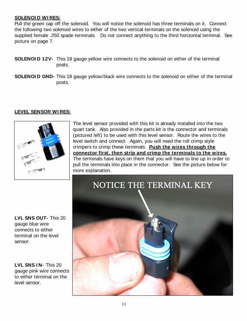
The level sensor provided with this kit is already installed into the two quart tank. Also provided in the parts kit is the connector and terminals (pictured left) to be used with this level sensor. Route the wires to the level switch and connect. Again, you will need the roll crimp style crimpers to crimp these terminals. Push the wires through the connector first, then strip and crimp the terminals to the wires. The terminals have keys on them that you will have to line up in order to pull the terminals into place in the connector. See the picture below for more explanation.
LVL SNS OUT- This 20 gauge blue wire connects to either terminal on the level sensor. LVL SNS IN- This 20 gauge pink wire connects to either terminal on the level sensor.

14
DASH SECTION WIRES: LOW WATER INDICATION LED WIRES: Included in the parts kit is a red LED to be used for low water/methanol injection indication. The light will illuminate when low water/methanol level is indicated to the ColdShot II module by the level switch mounted in the reservoir. Locate a good place to mount the LED. Drill a 5/32” hole. Push the LED into the hole and connect the wires as listed below. LED GROUND- The 20 gauge black ground wire connects to the black wire on the LED. LED POWER- The 20 gauge red wire connects to the red wire on the LED.
INJECTION INDICATION LED WIRES: Included in the parts kit is a green LED to be used for injection indication. The light will illuminate when the ColdShot II controller is commanding injection to occur. Locate a good place to mount the LED. Drill a 5/32” hole. Push the LED into the hole and connect the wires as listed below. LED GROUND- The 20 gauge yellow/black wire connects to the black wires on the LED LED POWER- The 20 gauge yellow wire connects to the red wire on the LED.
Water/Methanol Mix: It is up to you to decide what to inject your vehicle with. Here are some general guidelines.
1. The water/methanol mix usually will contain from 20% to 50% methanol. We suggest you do not use more than a 50% mix of methanol. Use distilled water for the water content of the water/methanol mix.
2. You can purchase denatured alcohol from your local hardware store. Denatured alcohol is
ethanol with methanol mixed in to make it denatured or poisonous. This denatured alcohol will work but the benefits won’t be as noticeable when compared to using methanol.
3. Windshield washer fluid is cheap and will work as an injection fluid. Many of these windshield
washer fluids are around 20-40 percent methanol, with the rest of its makeup being water and soap. It is not recommended to use the brands that include soap in their contents.
4. Always keep the water/methanol mix in a sealed container. Methanol evaporates very quickly
and absorbs water out of the air.
5. Mix and store the water and methanol in a clean container rated for methanol use.

15
Initial Start-up: Hook the vehicle’s batteries back up. If needed, plug the relay and fuse into the relay harness. Fill the tank with your choice of water/methanol mixture. This section of the installation manual walks you through the user set up. Turn the key to the vehicle to the on position. The module will power up. Cycle through the different settings and modify them as you see fit.
ON/OFF/MAP CALIBRATE: This button allows you to turn the module on/off without having to shut the vehicle’s ignition off. *MAP calibration is also initiated with this button. The on board MAP must be calibrated at the initial activation of the system in order for the module to accurately inject water/methanol. To do this you must have the module turned on. Press and hold the button for 5 seconds. The display will show CA when the module has finished calibrating the MAP. Now press the button to turn the module off and then back on. *MAP calibration is required if significant altitude changes occur. The module will operate without recalibration of the MAP after an altitude change but may not show the proper boost readout.* MODE/SELECT, UP & DOWN: Press the mode button once. The display will show S which stands for boost setting for the module to initiate water/methanol injection. Press the up or down buttons to select your desired setting. Press the mode button again. The display will show F which stands for boost setting for the module to command full injection from the pump. Press the up or down buttons to select your desired setting.
16
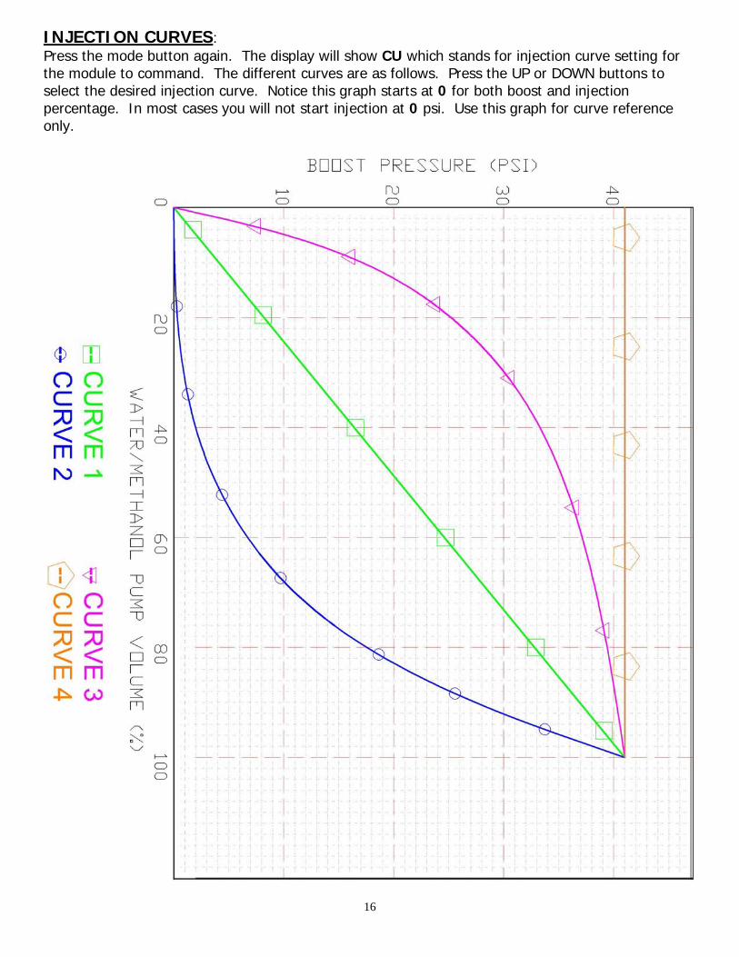
INJECTION CURVES: Press the mode button again. The display will show CU which stands for injection curve setting for the module to command. The different curves are as follows. Press the UP or DOWN buttons to select the desired injection curve. Notice this graph starts at 0 for both boost and injection percentage. In most cases you will not start injection at 0 psi. Use this graph for curve reference only.

17
The Cold Shot II module can be operated in either of the two modes listed below. The user menu is cyclical and will continue to cycle through the different set up and display modes as you push the mode button. Boost: After selecting the injection curve press the mode button once for the display to show PS. In this mode the Cold Shot II module displays the boost it registers via the boost reference tube. Injection amount: Press the mode button one more time for display to show IA. IA is short for Injection Amount. This display mode shows injection amount according to percentage and ranges from 0-99%. Set up is now done. Go drive the vehicle. Keep an eye on the module to make sure you seeing a boost pressure reading or injection percentage amount on the display. You should also hear the solenoid click open and you might hear the pump start turning at the start boost pressure setting. User menu cycle:
S=> F=> CU=> PS=> IA=> S
Combustion Quench: If while driving the vehicle you experience the engine bucking, do any of the following to remedy the problem. Combustion quench is caused by either too much fluid being injected or not enough air flow to accommodate what is being injected. 1. Start the injection at a higher boost level. 2. Change the injection curve to a less aggressive curve. 3. Use a smaller injection nozzle.
After Injection Run Time: Always allow the engine to run for 4-5 minutes after injecting before you shut it off. This will eliminate any residual water/methanol in the intake.
18
TROUBLE SHOOTING ISSUES: NO BOOST READING ON DISPLAY WHEN VEHICLE IS UNDER BOOST:
• This is most likely caused by the boost reference tubing being either kinked or slipped off of the nipple on the intake. Double check that neither of these situations is causing the no boost reference issue.
NO INJECTION WHEN VEHICLE IS UNDER BOOST:
• This can be caused by ColdShot II module not seeing boost reference. Check the boost reference tube is not kinked or unhooked. Check your settings for start and full injection pressures. Make sure you have them set properly for your application.
• This can be caused by the pump not being primed. Re-prime the pump according to the
instructions on page 12.
• This can be caused by improper settings for the Start and Finish injection pressures. Check to be sure you have these two settings correct for your boosted application.
COLD SHOT II MODULE DOES NOT POWER UP: • This can be caused by an improper ground source. Check for continuity to ground where you
connected the 14 gauge black wire. • This can be caused by an improper ignition source for the relay. Make sure when the ignition
key is turned on that there is 12 Volts on the 20 gauge pink wire coming from the relay. Also, check for ground on the black wire coming from the relay. You can also hold your finger on the relay when the ignition is turned on. If the relay is operating you will feel a click from it as the ignition switch is turned on.
• If the relay is operating then double check your crimp connection between the relay output
orange wire and 14 gauge orange wire from the ColdShot II harness. Since this wire is what actually turns on the ColdShot II module, a bad connection here will definitely cause a power up problem.
Painless Performance Limited Warranty And Return Policy
Chassis harnesses, fuel injection harnesses and Striker ColdShot are covered under a lifetime warranty. All other products manufactured and/or sold by Painless Performance are warranted to the original purchaser to be free from defects in material and workmanship under normal use. Painless Performance will repair or replace defective products without charge during the first 12 months from the purchase date. No products will be considered for warranty without a copy of the purchase receipt showing the sellers name, address, and date of purchase. You must return the product to the dealer you purchased it from to initiate warranty procedures.

19
Installation Notes: __________________________________________________________________________________________________________________________ __________________________________________________________________________________________________________________________ __________________________________________________________________________________________________________________________ __________________________________________________________________________________________________________________________ __________________________________________________________________________________________________________________________