installation instructions - dcs appliances · installation instructions. ... dcs by fisher &...
TRANSCRIPT

US CA NZ AU
590615C 03.15
TDS1-20, TDD1-20, TDT1-20, TB1-20, DP1-42 & BC25 models
Outdoor Storage
INSTALLATION INSTRUCTIONS

SAFETY AND WARNINGS1
• Closing drawers may cause injury to your hands or fingers.
• Always close or open drawers using their handles.
• Be sure to keep hands away from drawer edges when opening or closing drawers.
WARNING
IMPORTANT SAFETY INSTRUCTIONS! Do not remove permanently affixed labels, warnings, or plates from the product. This may void the
warranty. Please make this information available to the person installing the appliance as it could reduce your
installation costs. Please leave these instructions with the appliance. Inform the customer to retain for future reference
and for the local inspectors’ use. Failure to install the appliance correctly could invalidate any warranty or liability claims. Only genuine replacement parts may be used for servicing the appliance. These are available from
your nearest Fisher & Paykel Service Center.
the countertop is square and level and no structural members interfere with space requirements Do Not store or use gasoline or other flammable vapors and liquids inside or in the vicinity of this or
any other appliance. An LP cylinder not connected for use shall not be stored inside or in the vicinity of this unit.
WARNING!
Cut hazard
Take care - panel edges are sharp.
Failure to use caution could result in injury or cuts.
WARNING!
Crush hazard Closing drawers may cause injury to your hands or fingers. Always close or open drawers using their handles. Be sure to keep hands away from drawer edges when opening or closing drawers.
Failure to use caution could result in injury or cuts.

3MODEL LINE UP
TOOLS REQUIRED (NOT SUPPLIED)
2
3
TDS1-20
TDD1-20
TDT1-20DP1-42
TB1-20BC25
DRAWERS WASTE BASKET BEVERAGE CHILLERPANTRY
BOTTLE HOLDER
Screwdriver 2 - WrenchTape
measure Safety GlassesPencil
Adjustablepliers
Adjustablewrench
Suitable protectivegloves Drill
Hammer
BC-BOTTLEAC-25

44 PRODUCT DIMENSIONS - DRAWERS, PANTRY & WASTE BASKET
Product dimensions inches (mm) TDS1-20
TDD
1-20
TDT1-20
TB1-20
DP1-42
A overall height of product 9 5/8” (245) 21 7/8” (556) 29 1/8” (740) 29 1/8” (740) 30 1/2” (775)
B overall width of product 20 5/16” (516) 20 5/16” (516) 20 5/16” (516) 20 5/16” (516) 42” (1066)
C width of chassis 18 1/2” (469) 18 1/2” (469) 18 1/2” (469) 18 1/2” (469) 40 ” (1016)
D depth of chassis 23 ” (585) 23 ” (585) 23 ” (585) 23 ” (585) 23 11/16” (601)
E depth of front frame (excluding handle) 2” (51) 2” (51) 2” (51) 2” (51) 2” (51)
F height of chassis 8 5/16” (210) 20 1/2” (520) 27 13/16” (705) 27 13/16” (705) 29” (736)
TOP
C
D
EB
AF
FRONT SIDE
TB1-20 model shown for illustration purposes
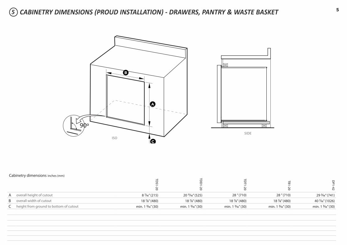
55 CABINETRY DIMENSIONS (PROUD INSTALLATION) - DRAWERS, PANTRY & WASTE BASKET
Cabinetry dimensions inches (mm) TDS1-20
TDD
1-20
TDT1-20
TB1-20
DP1-42
A overall height of cutout 8 7/16” (215) 20 11/16” (525) 28 ” (710) 28 ” (710) 29 3/16” (741)
B overall width of cutout 18 7/8” (480) 18 7/8” (480) 18 7/8” (480) 18 7/8” (480) 40 7/16” (1026)
C height from ground to bottom of cutout min. 1 3/16” (30) min. 1 3/16” (30) min. 1 3/16” (30) min. 1 3/16” (30) min. 1 3/16” (30)
90º
A
C
B
SIDEISO

65 CABINETRY DIMENSIONS (FLUSH INSTALLATION) - DRAWERS, PANTRY & WASTE BASKET
Cabinetry dimensions inches (mm) TDS1-20
TDD
1-20
TDT1-20
TB1-20
DP1-42
A overall height of cutout 9 13/16” (249) 22 1/16” (560) 29 5/16” (745) 29 5/16” (745) 30 11/16” (779)
B overall width of cutout 20 1/2” (521) 20 1/2” (521) 20 1/2” (521) 20 1/2” (521) 42 3/16” (1072)
C height from ground to bottom of cutout min. 1 3/16” (30) min. 1 3/16” (30) min. 1 3/16” (30) min. 1 3/16” (30) min. 1 3/16” (30)
D setback for flush installation 2” (51) 2” (51) 2” (51) 2” (51) 2” (51)
90º
A
C
D
B
TB1-20 model shown for illustration purposes
FRONT SIDE
Minimum 3/16” (4 mm) cutout clearance around front frame
A frame should be constructed 2” (51 mm) setback from the front face of the product to both push the product up against and conceal the cutout clearance around the front frame.
Important! Do not seal the product in with silicone caulk or similiar. Doing so willresult in the product being difficult to remove for servicing.
ISO

7
B
B
C F
D
E
A
K
90º
H
I
G
90º
H
J
G
I
B
B
C F
D
E
A
K
90º
H
I
G
90º
H
J
G
I
6 PRODUCT & CABINETRY DIMENSIONS - BEVERAGE CHILLER / BOTTLE HOLDER
Cabinetry dimensions inches (mm)
BC25
A overall depth of product (including lid) 21 15/16” (557)
B overall width of product (including lid) 26 3/8” (670)
BI overall width of product (excluding lid) 25 1/16” (636)
C width of chassis 23 15/16” (608)
D height of chassis (below countertop) 9 13/16” (249)
E height of frame (including lid) 2 1/4” (57)
F distance from rear of chassis to centre of drain 5 9/16” (142)
G overall width of cutout 24 3/16” (615)
Hdepth of cutout: without bottle holder accessory including bottle holder accessory
21 1/16” (535)21 11/16” (550)
I minimum distance from front of countertop to cutout 5/8” (15)
J height of cutout for bottle holder accessory 9 7/8” (250)
K depth of bottle holder at widest point to front of frame 6 5/8” (168)
TOP
B
B
C F
D
E
A
K
90º
H
I
G
90º
H
J
G
I
FRONT SIDE
WITHOUT BOTTLE HOLDER ACCESSORY INCLUDING BOTTLE HOLDER ACCESSORYTB1-20 model shown for illustration purposes
Make sure the countertop is square and level and no structural members interfere with space requirements.

8
7a DISCARD PACKAGING
GAS
ON
GAS
ON
1
2
Fibre washerFloating nut Elbow (½” BSP external thread)
Foam TapeAdhesive side
20 mm
50 mm
+50 mm
NG
ALL ModelsMake sure the connection point will be accessible with the cooktop installed.To enable the gas supply to be readily shut o� by the customer, make sure the connectionis �tted with an isolating valve close to the cooktop.
Adjust to obtain a test pointpressure of 1 kPa with all theburners operating at highest setting.
Ensure the hose is long enough to allow for removal of cooktop for servicing.Make sure the connector is located as shown in step 5 CLEARANCE DIMENSIONS.The hose assembly must be AS/NZS 1869 Class B or D certi�ed, with an Rp ½” (ISO 7‐1) female thread connection.The hose assembly must be as short as practicable and comply with relevant AS 5601/NZS 5261 requirements.The hose must not be kinked, subjected to abrasion or permanently deformed.The hose must not be near or in contact with any hot surfaces (e.g. base of metal hotlplate, �ue, or chassis of underbench oven etc.)
If connecting the gas with a �exible hose:
LPG
recessed to 50 mm
check all connections
Make sure the supply pressure is regulated to 2.75 kPa, withall the burners operating at highest setting.
If converting to LPG, see 16 'Converting to a di�erent gas type'
To check that the ignition system operates correctly, light each burner by itself, then all burners in combination.Check for a well‐de�ned blue �ame without any yellow tipping.If any abnormality is evident, check that the components of the burner assembly are located properlyIf proper operation cannot be obtained, contact your nearest F&P Authorised Service Centre. The cooktop must not be used by the customer until proper operation has been achieved.
yellow tiplifting o�
good �ame
Arrow
Recycle responsibly
Model may vary from illustrations shown
8a REMOVE ALL DRAWERS TO ACCESS SCREW HOLE LOCATIONS
Inspect the product(s) to verify that there is no shipping damage.If any damage is detected, call the shipper and initiate a damage claim. DCS by Fisher & Paykel is not responsible for shipping damage.
NOTE: Do not discard any packing material until the unit has been inspected. Operate the drawers to be sure they glide smoothly.Examine the fronts to be sure there are no dents or scratches or discoloring.
INSTALLING DRAWER UNITS, WASTE BASKET
To remove the drawer(s)1 Remove the drawers by pulling them
out until the slider latch is visible.2 Carefully push the latch down on the
left side, while lifting up the latch on the right side.
3 Pull the drawer out of the frame.Note: to prevent damage to surfaces, placethe drawers on a stable surface on aprotective towel or table cloth.
Left Slider latch
Right Slider latch
CORNER INSTALLATION

9INSTALLING DRAWER UNITS, WASTE BASKET
Allow min. 1 1/8” (28mm) clearance from the cutout to a
corner
Allow min. 4” (102 mm) clearance from the cutout to a corner
Refer to Pantry installation for corner installations with a pantry unit or beverage unit with bottle holder.
measured from back of frame
measured from back of frame
9a PREPARE THE CAVITY
Ensure the cavity is level, square and able to support the weight of the product when full.
Any cabinet and/or ground preparation must be completed prior to installation. All support structures must be constructed of materials resistant to moisture
damage. Do no use harsh products (acid, solvent, sealers) around this product.
1 Depending on your construction, place either a shelf or at least two (min 2” (51 mm) wide) moisture resistant supports in the cutout. Ensure all support boards are flat and level.
min. 1 1⁄8” (28 mm)
min. 7⁄16” (11 mm)
min. 13⁄16” (30 mm)
min. 7⁄16” (11 mm)
min. 13⁄16” (30 mm) 5⁄8” (16 mm)
16 ½” (420 mm)
16 ½” (420 mm)
20 ½” (520 mm)
20 ½” (520 mm)
1 ¼” (31 mm)
1 ¼” (31 mm)
1 3⁄8” (35 mm)
3 ¾” (95 mm)
10 ¼” (260 mm)
3 ¾” (95 mm)
min. 1 1⁄8” (28 mm)
min. 7⁄16” (11 mm)
min. 13⁄16” (30 mm)
min. 7⁄16” (11 mm)
min. 13⁄16” (30 mm) 5⁄8” (16 mm)
16 ½” (420 mm)
16 ½” (420 mm)
20 ½” (520 mm)
20 ½” (520 mm)
1 ¼” (31 mm)
1 ¼” (31 mm)
1 3⁄8” (35 mm)
3 ¾” (95 mm)
10 ¼” (260 mm)
3 ¾” (95 mm)
min. 1 1⁄8” (28 mm)
min. 7⁄16” (11 mm)
min. 13⁄16” (30 mm)
min. 7⁄16” (11 mm)
min. 13⁄16” (30 mm) 5⁄8” (16 mm)
16 ½” (420 mm)
16 ½” (420 mm)
20 ½” (520 mm)
20 ½” (520 mm)
1 ¼” (31 mm)
1 ¼” (31 mm)
1 3⁄8” (35 mm)
3 ¾” (95 mm)
10 ¼” (260 mm)
3 ¾” (95 mm)
min. 1 1⁄8” (28 mm)min. 4” (102 mm)
min. 4” (102 mm)
TDS1-20 ONLY
CORNER INSTALLATION
CORNER INSTALLATION WITH TWO PRODUCTS
Provide a support behind the chassis to screw into
TDD1-20, TDT1-20 & TB1-20 ONLY
Provide a support above the chassis to screw up into

1010a INSERT PRODUCT INTO CAVITY & SECURE
1 With the help of an assistant, lift the unit and slide it into the cabinet cutout along the supports. Adjust for level and fit.2 Locate the mounting holes (front and rear of base on each side).
Single Drawer TDS1-20 only: If you find the rear base screw hole locations inaccessible, you may screw through the rear chassis panel into the support behind the unit.
3 Secure the unit using screws suitable for the type of cabinetry materials used. We recommend using all the shown hole locations for securing.
min. 1 1⁄8” (28 mm)
min. 7⁄16” (11 mm)
min. 13⁄16” (30 mm)
min. 7⁄16” (11 mm)
min. 13⁄16” (30 mm) 5⁄8” (16 mm)
16 ½” (420 mm)
16 ½” (420 mm)
20 ½” (520 mm)
20 ½” (520 mm)
1 ¼” (31 mm)
1 ¼” (31 mm)
1 3⁄8” (35 mm)
3 ¾” (95 mm)
10 ¼” (260 mm)
3 ¾” (95 mm)
min. 1 1⁄8” (28 mm)
min. 7⁄16” (11 mm)
min. 13⁄16” (30 mm)
min. 7⁄16” (11 mm)
min. 13⁄16” (30 mm) 5⁄8” (16 mm)
16 ½” (420 mm)
16 ½” (420 mm)
20 ½” (520 mm)
20 ½” (520 mm)
1 ¼” (31 mm)
1 ¼” (31 mm)
1 3⁄8” (35 mm)
3 ¾” (95 mm)
10 ¼” (260 mm)
3 ¾” (95 mm)
min. 1 1⁄8” (28 mm)
min. 7⁄16” (11 mm)
min. 13⁄16” (30 mm)
min. 7⁄16” (11 mm)
min. 13⁄16” (30 mm) 5⁄8” (16 mm)
16 ½” (420 mm)
16 ½” (420 mm)
20 ½” (520 mm)
20 ½” (520 mm)
1 ¼” (31 mm)
1 ¼” (31 mm)
1 3⁄8” (35 mm)
3 ¾” (95 mm)
10 ¼” (260 mm)
3 ¾” (95 mm)
min. 1 1⁄8” (28 mm)
min. 7⁄16” (11 mm)
min. 13⁄16” (30 mm)
min. 7⁄16” (11 mm)
min. 13⁄16” (30 mm) 5⁄8” (16 mm)
16 ½” (420 mm)
16 ½” (420 mm)
20 ½” (520 mm)
20 ½” (520 mm)
1 ¼” (31 mm)
1 ¼” (31 mm)
1 3⁄8” (35 mm)
3 ¾” (95 mm)
10 ¼” (260 mm)
3 ¾” (95 mm)
TDD1-20, TDT1-20 & TB1-20 ONLY
Alternatively screw through rear chassis panel into support behind Refer to Step 9a for screw
mounting hole positions
Refer to Step 9a for screw mounting hole positions
TDS1-20 ONLY
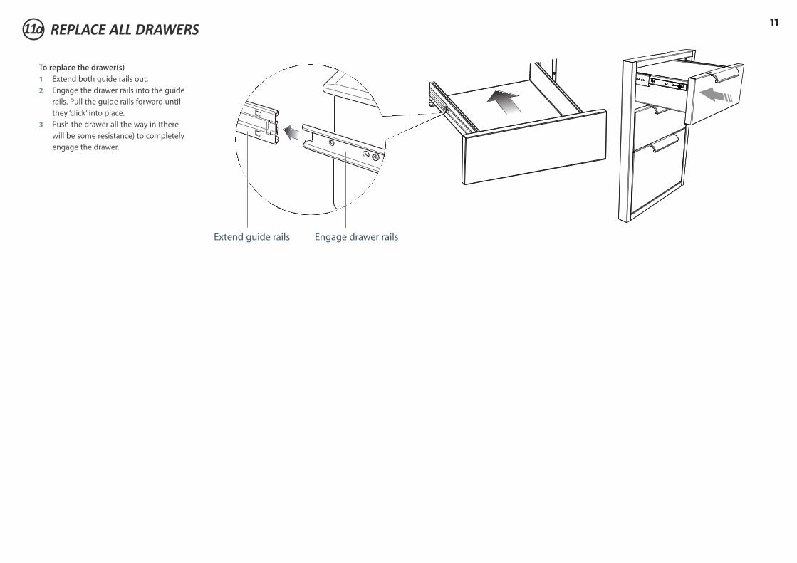
1111a REPLACE ALL DRAWERS
To replace the drawer(s)1 Extend both guide rails out.2 Engage the drawer rails into the guide
rails. Pull the guide rails forward until they ‘click’ into place.
3 Push the drawer all the way in (there will be some resistance) to completely engage the drawer.
Extend guide rails Engage drawer rails

12
7b DISCARD PACKAGING
GAS
ON
GAS
ON
1
2
Fibre washerFloating nut Elbow (½” BSP external thread)
Foam TapeAdhesive side
20 mm
50 mm
+50 mm
NG
ALL ModelsMake sure the connection point will be accessible with the cooktop installed.To enable the gas supply to be readily shut o� by the customer, make sure the connectionis �tted with an isolating valve close to the cooktop.
Adjust to obtain a test pointpressure of 1 kPa with all theburners operating at highest setting.
Ensure the hose is long enough to allow for removal of cooktop for servicing.Make sure the connector is located as shown in step 5 CLEARANCE DIMENSIONS.The hose assembly must be AS/NZS 1869 Class B or D certi�ed, with an Rp ½” (ISO 7‐1) female thread connection.The hose assembly must be as short as practicable and comply with relevant AS 5601/NZS 5261 requirements.The hose must not be kinked, subjected to abrasion or permanently deformed.The hose must not be near or in contact with any hot surfaces (e.g. base of metal hotlplate, �ue, or chassis of underbench oven etc.)
If connecting the gas with a �exible hose:
LPG
recessed to 50 mm
check all connections
Make sure the supply pressure is regulated to 2.75 kPa, withall the burners operating at highest setting.
If converting to LPG, see 16 'Converting to a di�erent gas type'
To check that the ignition system operates correctly, light each burner by itself, then all burners in combination.Check for a well‐de�ned blue �ame without any yellow tipping.If any abnormality is evident, check that the components of the burner assembly are located properlyIf proper operation cannot be obtained, contact your nearest F&P Authorised Service Centre. The cooktop must not be used by the customer until proper operation has been achieved.
yellow tiplifting o�
good �ame
Arrow
Recycle responsibly
Model may vary from illustrations shown
8b REMOVE ALL DRAWERS and SHELVES TO ACCESS SCREW HOLE LOCATIONS
Inspect the product(s) to verify that there is no shipping damage.If any damage is detected, call the shipper and initiate a damage claim. DCS by Fisher & Paykel is not responsible for shipping damage.
NOTE: Do not discard any packing material until the unit has been inspected. Operate the drawers and shelves to be sure they glide smoothly.Examine the fronts to be sure there are no dents or scratches or discoloring.
Exercise caution if fully opening the pantry doors. The outer frame could mark the door fronts.
To remove the drawer(s)1 Remove the drawers by pulling them
out until the slider latch is visible.2 Carefully push the latch down on the
left side, while lifting up the latch on the right side.
3 Pull the drawer out of the frame.Note: to prevent damage to surfaces, placethe drawers on a stable surface on aprotective towel or table cloth.
Left Slider latch
Right Slider latch
INSTALLING PANTRY UNIT
CORNER INSTALLATIONS

139b PREPARE THE CAVITY
Ensure the cavity is level, square and able to support the weight of the product when full. Any cabinet and/or ground preparation must be completed prior to installation. All support structures must be constructed of materials resistant to moisture damage. Do no use harsh products (acid, solvent, sealers) around this product.
1 Depending on your construction, place either a shelf or at least two (min 2” (51 mm) wide) moisture resistant supports in the cutout, paying special attention to the “step” on the base of the chassis. Ensure all support boards are flat and level.2 Provide a similiar support above the chassis to screw up into as shown.
min. 1 1⁄8” (28 mm)
min. 7⁄16” (11 mm)
min. 13⁄16” (30 mm)
min. 7⁄16” (11 mm)
min. 13⁄16” (30 mm) 5⁄8” (16 mm)
16 ½” (420 mm)
16 ½” (420 mm)
20 ½” (520 mm)
20 ½” (520 mm)
1 ¼” (31 mm)
1 ¼” (31 mm)
1 3⁄8” (35 mm)
3 ¾” (95 mm)
10 ¼” (260 mm)
3 ¾” (95 mm)
min. 1 1⁄8” (28 mm)
min. 7⁄16” (11 mm)
min. 13⁄16” (30 mm)
min. 7⁄16” (11 mm)
min. 13⁄16” (30 mm) 5⁄8” (16 mm)
16 ½” (420 mm)
16 ½” (420 mm)
20 ½” (520 mm)
20 ½” (520 mm)
1 ¼” (31 mm)
1 ¼” (31 mm)
1 3⁄8” (35 mm)
3 ¾” (95 mm)
10 ¼” (260 mm)
3 ¾” (95 mm)
Provide a support above the chassis to screw up into
There is an additional “step” on the pantry chassis that must be considered when locating the supports
INSTALLING PANTRY UNIT
Allow min. 1 1/8” (28mm) clearance from the cutout to a
corner
Pantry unit and drawer / waste binAllow min. 6 1/2” (165mm) clearance from the cutout
to the corner for each product.
Pantry unit and Beverage chiller with bottle holderAllow min. 9 1/2” (241mm) clearance from the cutout
to the corner for each product
min. 1 1⁄8” (28 mm)
min. 7⁄16” (11 mm)
min. 13⁄16” (30 mm)
min. 7⁄16” (11 mm)
min. 13⁄16” (30 mm) 5⁄8” (16 mm)
16 ½” (420 mm)
16 ½” (420 mm)
20 ½” (520 mm)
20 ½” (520 mm)
1 ¼” (31 mm)
1 ¼” (31 mm)
1 3⁄8” (35 mm)
3 ¾” (95 mm)
10 ¼” (260 mm)
3 ¾” (95 mm)
min. 1 1⁄8” (28 mm)min. 6 ½” (165 mm)
min. 6 ½” (165 mm)
CORNER INSTALLATIONS
CORNER INSTALLATIONS WITH TWO PRODUCTS (INCLUDING PANTRY)
measured from back of frame

1410b INSERT PRODUCT INTO CAVITY & SECURE
1 With the help of an assistant, lift the unit and slide it into the cabinet cutout along the supports. Adjust for level and fit.2 Locate the mounting holes (front top left and right sides and front base of drawer compartment). 3 Remove the transit plugs from the holes you intend to use.4 Secure the unit using countersunk screws suitable for the type of cabinetry materials used. We recommend using all the shown hole locations for securing.
min. 1 1⁄8” (28 mm)
min. 7⁄16” (11 mm)
min. 13⁄16” (30 mm)
min. 7⁄16” (11 mm)
min. 13⁄16” (30 mm) 5⁄8” (16 mm)
16 ½” (420 mm)
16 ½” (420 mm)
20 ½” (520 mm)
20 ½” (520 mm)
1 ¼” (31 mm)
1 ¼” (31 mm)
1 3⁄8” (35 mm)
3 ¾” (95 mm)
10 ¼” (260 mm)
3 ¾” (95 mm)
min. 1 1⁄8” (28 mm)
min. 7⁄16” (11 mm)
min. 13⁄16” (30 mm)
min. 7⁄16” (11 mm)
min. 13⁄16” (30 mm) 5⁄8” (16 mm)
16 ½” (420 mm)
16 ½” (420 mm)
20 ½” (520 mm)
20 ½” (520 mm)
1 ¼” (31 mm)
1 ¼” (31 mm)
1 3⁄8” (35 mm)
3 ¾” (95 mm)
10 ¼” (260 mm)
3 ¾” (95 mm)
Refer to Step 9b for screw mounting hole positions

1511b REPLACE ALL DRAWERS & SHELVES
To replace the drawer(s)1 Extend both guide rails out.2 Engage the drawer rails into the guide
rails. Pull the guide rails forward until they ‘click’ into place.
3 Push the drawer all the way in (there will be some resistance) to completely engage the drawer.
Extend guide rails Engage drawer rails
16
7c
9c
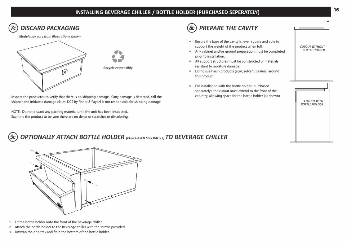
DISCARD PACKAGING
OPTIONALLY ATTACH BOTTLE HOLDER (PURCHASED SEPERATELY) TO BEVERAGE CHILLER
GAS
ON
GAS
ON
1
2
Fibre washerFloating nut Elbow (½” BSP external thread)
Foam TapeAdhesive side
20 mm
50 mm
+50 mm
NG
ALL ModelsMake sure the connection point will be accessible with the cooktop installed.To enable the gas supply to be readily shut o� by the customer, make sure the connectionis �tted with an isolating valve close to the cooktop.
Adjust to obtain a test pointpressure of 1 kPa with all theburners operating at highest setting.
Ensure the hose is long enough to allow for removal of cooktop for servicing.Make sure the connector is located as shown in step 5 CLEARANCE DIMENSIONS.The hose assembly must be AS/NZS 1869 Class B or D certi�ed, with an Rp ½” (ISO 7‐1) female thread connection.The hose assembly must be as short as practicable and comply with relevant AS 5601/NZS 5261 requirements.The hose must not be kinked, subjected to abrasion or permanently deformed.The hose must not be near or in contact with any hot surfaces (e.g. base of metal hotlplate, �ue, or chassis of underbench oven etc.)
If connecting the gas with a �exible hose:
LPG
recessed to 50 mm
check all connections
Make sure the supply pressure is regulated to 2.75 kPa, withall the burners operating at highest setting.
If converting to LPG, see 16 'Converting to a di�erent gas type'
To check that the ignition system operates correctly, light each burner by itself, then all burners in combination.Check for a well‐de�ned blue �ame without any yellow tipping.If any abnormality is evident, check that the components of the burner assembly are located properlyIf proper operation cannot be obtained, contact your nearest F&P Authorised Service Centre. The cooktop must not be used by the customer until proper operation has been achieved.
yellow tiplifting o�
good �ame
Arrow
Recycle responsibly
Model may vary from illustrations shown
Inspect the product(s) to verify that there is no shipping damage. If any damage is detected, call theshipper and initiate a damage claim. DCS by Fisher & Paykel is not responsible for shipping damage.
NOTE: Do not discard any packing material until the unit has been inspected. Examine the product to be sure there are no dents or scratches or discoloring.
each side
13/16” - 2 “(20-51 mm)
each side
13/16” - 2 “(20-51 mm)
8c PREPARE THE CAVITY
Ensure the base of the cavity is level, square and able to support the weight of the product when full.
Any cabinet and/or ground preparation must be completed prior to installation.
All support structures must be constructed of materials resistant to moisture damage.
Do no use harsh products (acid, solvent, sealers) around this product.
For installation with the Bottle holder (purchased separately), the cutout must extend to the front of the cabintry, allowing space for the bottle holder (as shown).
CUTOUT WITHOUT BOTTLE HOLDER
CUTOUT WITHBOTTLE HOLDER
INSTALLING BEVERAGE CHILLER / BOTTLE HOLDER (PURCHASED SEPERATELY)
1 Fit the bottle holder onto the front of the Beverage chiller.2 Attach the bottle holder to the Beverage chiller with the screws provided.3 Unwrap the drip tray and fit in the bottom of the bottle holder.

17
each side
13/16” - 2 “(20-51 mm)
each side
13/16” - 2 “(20-51 mm)
each side
13/16” - 2 “(20-51 mm)
10c LOWER PRODUCT INTO CUTOUT, ATTACH MOUNTING BRACKETS & SECURE
1 With the help of an assistant lower the chiller into the cutout, ensuring the drain outlet is accessible. 2 Locate the mounting holes on each side of the beverage chiller and screw in the provided mounting clamps at the appropriate level for the countertop. 3 Secure the beverage chiller into place by tightening the clamping screws against the countertop on two sides.
Each mounting clamp comes with 4 positions. Screw the clamps into the most appropriate position using the screws provided.
Drain outlet
It is recommended that the Beverage Chiller be connected to the permanent wastedrainage system.
Important! Connection to the existing drainage system must be carried out by certified plumber and inaccordance with local codes and regulations.
Drain Connection
USA and CanadaThe sink drain connection is 1-1/2” NPS male thread.
Australia and New ZealandA 1-1/2” BSP male thread connection is required. Attach the supplied 1 1/2” NPS male to 1 1/2” BSP thread adaptor.
11c CONNECT TO THE DRAINAGE SYSTEM

1812 FINAL CHECKLIST
Important! SAVE THESE INSTRUCTIONSThe models shown in this document may not be available in all markets and are subject to change at any time. For current details about model and specification availability in your country, please visit our website listed at the end of this document or contact your local Fisher & Paykel dealer.
www.fisherpaykel.com
TO BE COMPLETED BY THE INSTALLER
Are products secure and level within the enclosure? Are all the drawers, doors and shelves fitted correctly and open and shut smoothly?
Have you demonstrated the basic operation to the customer?
Are the soft close drawers working correctly? (Note: the pantry doors and drawers are not soft closing).
BC25 Beverage Chiller only:Have you installed the clamping brackets?
Has all the suitable plumbing connections been checked?
Installer’s name:
Installer’s signature:
Installation company:
Date of installation:
LEAVE THESE INSTRUCTIONS WITH THE CUSTOMER

19


US CA NZ AU
590615C 03.15
Modèles TDS1-20, TDD1-20, TDT1-20, TB1-20, DP1-42 et BC25
Solutions de rangement pour l’extérieur
INSTRUCTIONS D’INSTALLATION

2CONSIGNES DE SÉCURITÉ ET MISES EN GARDE1
• Closing drawers may cause injury to your hands or fingers.
• Always close or open drawers using their handles.
• Be sure to keep hands away from drawer edges when opening or closing drawers.
WARNING
CONSIGNES DE SÉCURITÉ IMPORTANTES! Ne retirez pas les étiquettes, mises en garde ou plaques signalétiques apposées de façon permanente
sur le produit. Cela pourrait entraîner l’annulation de la garantie. Remettez ces instructions à la personne qui installera l’appareil. Cela pourrait réduire vos coûts
d’installation. Laissez ces instructions avec l’appareil. Demandez au client de les conserver pour toute référence
ultérieure ou vérification des inspecteurs locaux. Le fait de ne pas installer l’appareil de façon adéquate pourrait entraîner l’annulation de toute
garantie ou réclamation. Utilisez uniquement des pièces de remplacement authentiques pour effectuer l’entretien
ou les réparations de l’appareil. Vous pouvez vous les procurer auprès d’un Centre de service Fisher & Paykel de votre région.
le comptoir est au niveau et bien droit, et aucune pièce de charpente ne nuit aux exigences de dégagement.
Ne rangez et n’utilisez pas de l’essence ou d’autres liquides et vapeurs inflammables à l’intérieur ou à proximité de cet appareil ou de tout autre appareil.
Ne rangez pas de bouteille de gaz de pétrole liquéfié déconnectée et inutilisée à l’intérieur ou à proximité de cet appareil.
MISE EN GARDE!
Risque de coupure
Attention, les bords du panneau sont tranchants.
Des blessures ou des coupures peuvent survenir si vous ne faites pas preuve de prudence.
MISE EN GARDE!
Risque d’écrasement La fermeture des tiroirs pourrait causer des blessures à vos mains ou doigts. Fermez ou ouvrez toujours les tiroirs en utilisant leur poignée. Assurez-vous d’éloigner les mains des rebords de tiroir lors de l’ouverture ou la
fermeture des tiroirs.
Des blessures ou des coupures peuvent survenir si vous ne faites pas preuve de prudence.

3GAMME DE MODÈLES
OUTILS REQUIS (NON FOURNIS)
2
3
TDS1-20
TDD1-20
TDT1-20DP1-42
TB1-20BC25
TIROIRS CORBEILLE À DÉCHETS REFROIDISSEUR DE BOISSONGARDE-MANGER
PORTE-BOUTEILLE
TournevisRuban
à mesurer Lunettes de sécuritéCrayon
Pincesajustables
Cléajustable
Gants de protectionPerceuse
Marteau
2 - Clé
BC-BOTTLEAC-25

44 DIMENSIONS DU PRODUIT - TIROIRS, GARDE-MANGER ET CORBEILLE À DÉCHETS
Dimensions du produit pouces (mm) TDS1-20
TDD
1-20
TDT1-20
TB1-20
DP1-42
A hauteur hors tout du produit 9 5/8 po (245) 21 7/8 po (556) 29 1/8 po (740) 29 1/8 po (740) 30 1/2 po (775)
B largeur hors tout du produit 20 5/16 po (516) 20 5/16 po (516) 20 5/16 po (516) 20 5/16 po (516) 42 po (1066)
C largeur du châssis 18 1/2 po (469) 18 1/2 po (469) 18 1/2 po (469) 18 1/2 po (469) 40 po (1016)
D profondeur du châssis 23 po (585) 23 po (585) 23 po (585) 23 po (585) 23 11/16 po (601)
E profondeur du cadre avant (excluant la poignée) 2 po (51) 2 po (51) 2 po (51) 2 po (51) 2 po (51)
F hauteur du châssis 8 5/16 po (210) 20 1/2 po (520) 27 13/16 po (705) 27 13/16 po (705) 29 po (736)
DESSUS
C
D
EB
AF
DEVANT CÔTÉ
Modèle TB1-20 présenté à titre indicatif

55 DIMENSIONS DU BÂTI (INSTALLATION SUPERPOSÉE) - TIROIRS, GARDE-MANGER ET CORBEILLE À DÉCHETS
Dimensions du bâti pouces (mm) TDS1-20
TDD
1-20
TDT1-20
TB1-20
DP1-42
A hauteur hors tout de l’ouverture 8 7/16 po (215) 20 11/16 po (525) 28 po (710) 28 po (710) 29 3/16 po (741)
B largeur hors tout de l’ouverture 18 7/8 po (480) 18 7/8 po (480) 18 7/8 po (480) 18 7/8 po (480) 40 7/16 po (1 026)
C hauteur entre le sol et le bas de l’ouverture min. 1 3/16 po (30) min. 1 3/16 po (30) min. 1 3/16 po (30) min. 1 3/16 po (30) min. 1 3/16 po (30)
90º
A
C
B
CÔTÉISO

65 DIMENSIONS DU BÂTI (INSTALLATION ENCASTRÉE) - TIROIRS, GARDE-MANGER ET CORBEILLE À DÉCHETS
Dimensions du bâti pouces (mm) TDS1-20
TDD
1-20
TDT1-20
TB1-20
DP1-42
A hauteur hors tout de l’ouverture 9 13/16 po (249) 22 1/16 po (560) 29 5/16 po (745) 29 5/16 po (745) 30 11/16 po (779)
B largeur hors tout de l’ouverture 20 1/2 po (521) 20 1/2 po (521) 20 1/2 po (521) 20 1/2 po (521) 42 3/16 po (1072)
C hauteur entre le sol et le bas de l’ouverture min. 1 3/16 po (30) min. 1 3/16 po (30) min. 1 3/16 po (30) min. 1 3/16 po (30) min. 1 3/16 po (30)
D retrait pour installation encastrée 2 po (51) 2 po (51) 2 po (51) 2 po (51) 2 po (51)
90º
A
C
D
B
Modèle TB1-20 présenté à titre indicatif
DEVANT CÔTÉ
Dégagement minimal de 3/16 po (4 mm) de l’ouverture autour du cadre avant
Un cadre doit être construit à 2 po (51 mm) en retrait de la face avant du produit pour permettre de pousser le produit contre le cadre avant et masquer le dégagement de l’ouverture autour de ce dernier.
Important! Ne scellez pas le produit à l’aide de silicone ou d’un scellant semblable. Sinon, le produit risque d’être difficile à retirer pour l’entretien.
ISO

7
B
B
C F
D
E
A
K
90º
H
I
G
90º
H
J
G
I
6 DIMENSIONS DU PRODUIT ET DU BÂTI - REFROIDISSEUR DE BOISSON / PORTE-BOUTEILLE
Dimensions du bâti pouces (mm)
BC25
A profondeur hors tout du produit (incluant le couvercle) 21 15/16 po (557)
B largeur hors tout du produit (incluant le couvercle) 26 3/8 po (670)
BI largeur hors tout du produit (excluant le couvercle) 25 1/16 po (636)
C largeur du châssis 23 15/16 po (608)
D hauteur du châssis 9 13/16 po (249)
E hauteur du cadre (incluant le couvercle) 2 1/4 po (57)
F distance entre l’arrière du châssis et le centre de la sortie de vidange 5 9/16 po (142)
G largeur hors tout de l’ouverture 24 3/16 po (615)
Hprofondeur de l’ouverture : sans porte-bouteille avec porte-bouteille
21 1/16 po (535)21 11/16 po (550)
I distance minimale entre le devant du comptoir et l’ouverture 5/8 po (15)
J hauteur de l’ouverture pour le porte-bouteille 9 7/8 po (250)
K profondeur du porte-bouteille au point le plus large à l’avant du cadre 6 5/8 po (168)
DESSUS
B
B
C F
D
E
A
K
90º
H
I
G
90º
H
J
G
I
DEVANT CÔTÉ
SANS PORTE-BOUTEILLE AVEC PORTE-BOUTEILLEModèle TB1-20 présenté à titre indicatif
B
B
C F
D
E
A
K
90º
H
I
G
90º
H
J
G
I
Assurez-vous que le plan de travail est d’équerre et aucun des éléments structurels interférer avec les besoins en espace.

8
7a METTEZ L’EMBALLAGE AU REBUT
GAS
ON
GAS
ON
1
2
Fibre washerFloating nut Elbow (½” BSP external thread)
Foam TapeAdhesive side
20 mm
50 mm
+50 mm
NG
ALL ModelsMake sure the connection point will be accessible with the cooktop installed.To enable the gas supply to be readily shut o� by the customer, make sure the connectionis �tted with an isolating valve close to the cooktop.
Make sure to �t the supplied washer and regulator.Adjust to obtain a test pointpressure of 1 kPa with the two semi-rapid burners operating at highest setting.
Ensure the hose is long enough to allow for removal of cooktop for servicing.Make sure the connector is located as shown in step 5 CLEARANCE DIMENSIONS.The hose assembly must be AS/NZS 1869 Class B or D certi�ed, with an Rp ½” (ISO 7‐1) female thread connection.The hose assembly must be as short as practicable and comply with relevant AS 5601/NZS 5261 requirements.The hose must not be kinked, subjected to abrasion or permanently deformed.The hose must not be near or in contact with any hot surfaces (e.g. base of metal hotlplate, �ue, or chassis of underbench oven etc.)
If connecting the gas with a �exible hose:
LPG
recessed to 50 mm
check all connections
Make sure to �t the supplied washer and test point adaptor.Make sure the supply pressure is regulated to 2.75 kPa, withthe two semi-rapid burners operating at highest setting.
WasherWasher
If converting to LPG, see 16 'Converting to a di�erent gas type'
To check that the ignition system operates correctly, light each burner by itself, then all burners in combination.Check for a well‐de�ned blue �ame without any yellow tipping.If any abnormality is evident, check that the components of the burner assembly are located properlyIf proper operation cannot be obtained, contact your nearest F&P Authorised Service Centre. The cooktop must not be used by the customer until proper operation has been achieved.
yellow tiplifting o�
good �ame
Arrow
Recyclez de façon responsable
Le modèle peut être différent des illustrations présentées
8a RETIREZ TOUS LES TIROIRS POUR ACCÉDER AUX EMPLACEMENTS DES OUVERTURES DE VIS
Inspectez le(s) produit(s) pour vous assurer qu’aucun dommage n’a été causé lors de l’expédition.En cas de dommage, communiquez avec l’expéditeur pour faire une demande d’indemnisation. DCS par Fisher & Paykel n’est pas responsable des dommages causés lors de l’expédition.
REMARQUE : Ne mettez pas au rebut les matériaux d’emballage avant d’avoir terminé l’inspection de l’appareil. Utilisez les tiroirs afin de vous assurer qu’ils glissent en douceur.Examinez les pièces à l’avant afin de vous assurer qu’elles ne présentent aucune bosselure, égratignure ou décoloration.
INSTALLATION DES TIROIRS ET DE LA CORBEILLE À DÉCHETS
Pour retirer le(s) tiroir(s)1 Retirez les tiroirs en les tirant vers
l’extérieur jusqu’à ce que le loquet de glissière soit visible.
2 Enfoncez doucement le loquet sur le côté gauche, tout en soulevant le loquet sur le côté droit.
3 Sortez le tiroir du cadre.Remarque : pour éviter d’endommager les surfaces, placez les tiroirs sur une surface stable recouverte d’une serviette ou d’une nappe protectrice.
Loquet de glissière gauche
Loquet de glissière droite
INSTALLATION DANS UN COIN
INSTALLATION DANS UN COIN AVEC DEUX PRODUITS

9
Laissez un dégagement d’au moins 1 1/8 po (28 mm) entre
l’ouverture et le coin
Laissez un dégagement d’au moins 4 po (102 mm) entre l’ouverture et le coin
Consultez la section d’installation du garde-manger pour les installations dans un coin avec un garde-manger ou un refroidisseur à boisson avec porte-bouteille.
9a PRÉPAREZ LA CAVITÉ
Assurez-vous que la cavité est de niveau, à angle droit et capable de supporter le poids du produit rempli à pleine capacité.
Toutes les préparations relatives au bâti et/ou au sol doivent être effectuées avant l’installation.
Toutes les structures de soutien doivent être construites à l’aide de matériaux résistant à l’humidité.
N’utilisez pas de produits abrasifs (acide, solvant, scellant) autour de ce produit.
1 Selon le type de construction, placez une tablette ou au moins deux supports résistant à l’humidité (min. 2 po (51 mm) de large) dans l’ouverture.
Assurez-vous que tous les panneaux de soutien sont plats et de niveau.
min. 1 1⁄8 po (28 mm)
min. 7⁄16 po(11 mm)
min. 13⁄16 po(30 mm)
min. 7⁄16 po(11 mm)
min. 13⁄16 po(30 mm) 5⁄8 po(16 mm)
16 ½ po(420 mm)
16 ½ po(420 mm)
20 ½ po(520 mm)
20 ½ po(520 mm)
1 ¼ po(31 mm)
1 ¼ po(31 mm)
1 3⁄8 po(35 mm)
3 ¾ po(95 mm)
10 ¼ po(260 mm)
3 ¾ po(95 mm)
min. 1 1⁄8 po (28 mm)
min. 7⁄16 po(11 mm)
min. 13⁄16 po(30 mm)
min. 7⁄16 po(11 mm)
min. 13⁄16 po(30 mm) 5⁄8 po(16 mm)
16 ½ po(420 mm)
16 ½ po(420 mm)
20 ½ po(520 mm)
20 ½ po(520 mm)
1 ¼ po(31 mm)
1 ¼ po(31 mm)
1 3⁄8 po(35 mm)
3 ¾ po(95 mm)
10 ¼ po(260 mm)
3 ¾ po(95 mm)
min. 1 1⁄8 po (28 mm)
min. 7⁄16 po(11 mm)
min. 13⁄16 po(30 mm)
min. 7⁄16 po(11 mm)
min. 13⁄16 po(30 mm) 5⁄8 po(16 mm)
16 ½ po(420 mm)
16 ½ po(420 mm)
20 ½ po(520 mm)
20 ½ po(520 mm)
1 ¼ po(31 mm)
1 ¼ po(31 mm)
1 3⁄8 po(35 mm)
3 ¾ po(95 mm)
10 ¼ po(260 mm)
3 ¾ po(95 mm)
min. 1 1⁄8 po (28 mm)min. 4 po (102 mm)
min. 4 po (102 mm)
TDS1-20 UNIQUEMENT
INSTALLATION DANS UN COIN
INSTALLATION DANS UN COIN AVEC DEUX PRODUITS
Fixez un support derrière le châssis pour permettre le vissage
Fixez un support au-dessus du châssis à visser dans
TDD1-20, TDT1-20 et TB1-20
mesure à partir de l’arrière du cadre
mesure à partir de l’arrière du cadre

1010a INSÉREZ LE PRODUIT DANS LA CAVITÉ ET FIXEZ-LE
1 Avec l’aide d’une personne, soulevez l’appareil et faites-le glisser le long des supports dans l’ouverture du bâti. Ajustez l’appareil de manière à l’installer de niveau, avec un positionnement adéquat.
2 Localisez les ouvertures de montage (à l’avant et l’arrière de la base, de chaque côté).
TDS1-20 à un seul tiroir uniquement : Si vous ne parvenez pas à accéder aux ouvertures de vis à l’arrière de la base, vous pouvez visser au travers du panneau de châssis arrière dans le support situé derrière l’appareil.
3 Fixez l’appareil à l’aide de vis adéquates pour le type de matériaux utilisés pour le bâti. Nous vous recommandons d’utiliser tous les emplacements d’ouvertures de vis illustrés pour fixer l’appareil.
min. 1 1⁄8” (28 mm)
min. 7⁄16” (11 mm)
min. 13⁄16” (30 mm)
min. 7⁄16” (11 mm)
min. 13⁄16” (30 mm) 5⁄8” (16 mm)
16 ½” (420 mm)
16 ½” (420 mm)
20 ½” (520 mm)
20 ½” (520 mm)
1 ¼” (31 mm)
1 ¼” (31 mm)
1 3⁄8” (35 mm)
3 ¾” (95 mm)
10 ¼” (260 mm)
3 ¾” (95 mm)
min. 1 1⁄8” (28 mm)
min. 7⁄16” (11 mm)
min. 13⁄16” (30 mm)
min. 7⁄16” (11 mm)
min. 13⁄16” (30 mm) 5⁄8” (16 mm)
16 ½” (420 mm)
16 ½” (420 mm)
20 ½” (520 mm)
20 ½” (520 mm)
1 ¼” (31 mm)
1 ¼” (31 mm)
1 3⁄8” (35 mm)
3 ¾” (95 mm)
10 ¼” (260 mm)
3 ¾” (95 mm)
min. 1 1⁄8” (28 mm)
min. 7⁄16” (11 mm)
min. 13⁄16” (30 mm)
min. 7⁄16” (11 mm)
min. 13⁄16” (30 mm) 5⁄8” (16 mm)
16 ½” (420 mm)
16 ½” (420 mm)
20 ½” (520 mm)
20 ½” (520 mm)
1 ¼” (31 mm)
1 ¼” (31 mm)
1 3⁄8” (35 mm)
3 ¾” (95 mm)
10 ¼” (260 mm)
3 ¾” (95 mm)
TDD1-20, TDT1-20 et TB1-20
Vous pouvez également visser au travers du panneau de châssis arrière dans le support situé derrière
Consultez l’Étape 9a pour localiser les emplacements des ouvertures de vis de montage
Consultez l’Étape 9a pour localiser les emplacements des ouvertures de vis de montage
TDS1-20 UNIQUEMENT
min. 1 1⁄8” (28 mm)
min. 7⁄16” (11 mm)
min. 13⁄16” (30 mm)
min. 7⁄16” (11 mm)
min. 13⁄16” (30 mm) 5⁄8” (16 mm)
16 ½” (420 mm)
16 ½” (420 mm)
20 ½” (520 mm)
20 ½” (520 mm)
1 ¼” (31 mm)
1 ¼” (31 mm)
1 3⁄8” (35 mm)
3 ¾” (95 mm)
10 ¼” (260 mm)
3 ¾” (95 mm)

1111a RÉINSÉREZ LES TIROIRS
Pour réinsérer le(s) tiroir(s)1 Étendez les deux rails de guidage vers
l’extérieur.2 Insérez les rails du tiroir dans les
rails de guidage. Tirez les rails de guidage vers l’avant jusqu’à ce qu’ils s’enclenchent.
3 Poussez le tiroir entièrement vers l’intérieur (il y aura une certaine résistance) pour l’insérer complètement.
Étendez les rails de guidage
Insérez les rails du tiroir

12
7b METTEZ L’EMBALLAGE AU REBUT
GAS
ON
GAS
ON
1
2
Fibre washerFloating nut Elbow (½” BSP external thread)
Foam TapeAdhesive side
20 mm
50 mm
+50 mm
NG
ALL ModelsMake sure the connection point will be accessible with the cooktop installed.To enable the gas supply to be readily shut o� by the customer, make sure the connectionis �tted with an isolating valve close to the cooktop.
Make sure to �t the supplied washer and regulator.Adjust to obtain a test pointpressure of 1 kPa with the two semi-rapid burners operating at highest setting.
Ensure the hose is long enough to allow for removal of cooktop for servicing.Make sure the connector is located as shown in step 5 CLEARANCE DIMENSIONS.The hose assembly must be AS/NZS 1869 Class B or D certi�ed, with an Rp ½” (ISO 7‐1) female thread connection.The hose assembly must be as short as practicable and comply with relevant AS 5601/NZS 5261 requirements.The hose must not be kinked, subjected to abrasion or permanently deformed.The hose must not be near or in contact with any hot surfaces (e.g. base of metal hotlplate, �ue, or chassis of underbench oven etc.)
If connecting the gas with a �exible hose:
LPG
recessed to 50 mm
check all connections
Make sure to �t the supplied washer and test point adaptor.Make sure the supply pressure is regulated to 2.75 kPa, withthe two semi-rapid burners operating at highest setting.
WasherWasher
If converting to LPG, see 16 'Converting to a di�erent gas type'
To check that the ignition system operates correctly, light each burner by itself, then all burners in combination.Check for a well‐de�ned blue �ame without any yellow tipping.If any abnormality is evident, check that the components of the burner assembly are located properlyIf proper operation cannot be obtained, contact your nearest F&P Authorised Service Centre. The cooktop must not be used by the customer until proper operation has been achieved.
yellow tiplifting o�
good �ame
Arrow
Recyclez de façon responsable
Le modèle peut être différent des illustrations présentées
8b RETIREZ TOUS LES TIROIRS ET TOUTES LES TABLETTES POUR ACCÉDER AUX EMPLACEMENTS DES OUVERTURES DE VIS
Inspectez le(s) produit(s) pour vous assurer qu’aucun dommage n’a été causé lors de l’expédition.En cas de dommage, communiquez avec l’expéditeur pour faire une demande d’indemnisation. DCS par Fisher & Paykel n’est pas responsable des dommages causés lors de l’expédition.
REMARQUE : Ne mettez pas au rebut les matériaux d’emballage avant d’avoir terminé l’inspection de l’appareil. Utilisez les tiroirs et les tablettes afin de vous assurer qu’ils glissent en douceur.Examinez les pièces à l’avant afin de vous assurer qu’elles ne présentent aucune bosselure, égratignure ou décoloration.
Faites preuve de prudence lors de l’ouverture complète des portes de garde-manger. Le cadre extérieur pourrait marquer le devant des portes.
Pour retirer le(s) tiroir(s)1 Retirez les tiroirs en les tirant vers
l’extérieur jusqu’à ce que le loquet de glissière soit visible.
2 Enfoncez doucement le loquet sur le côté gauche, tout en soulevant le loquet sur le côté droit.
3 Sortez le tiroir du cadre.Remarque : pour éviter d’endommager les surfaces, placez les tiroirs sur une surface stable recouverte d’une serviette ou d’une nappe protectrice.
Loquet de glissière gauche
Loquet de glissière droite
INSTALLATION DU GARDE-MANGER
INSTALLATIONS DANS UN COIN

139b PRÉPAREZ LA CAVITÉ
Assurez-vous que la cavité est de niveau, à angle droit et capable de supporter le poids du produit rempli à pleine capacité. Toutes les préparations relatives au bâti et/ou au sol doivent être effectuées avant l’installation. Toutes les structures de soutien doivent être construites à l’aide de matériaux résistant à l’humidité. N’utilisez pas de produits abrasifs (acide, solvant, scellant) autour de ce produit.
1 Selon le type de construction, placez une tablette ou au moins deux supports résistant à l’humidité (min. 2 po (51 mm) de large) dans l’ouverture, en portant une attention particulière à la « dénivellation » sur la base du châssis.
Assurez-vous que tous les panneaux de soutien sont plats et de niveau.2 Fixez un support semblable au-dessus du châssis pour permettre le vissage, tel qu’illustré.
min. 1 1⁄8 po (28 mm)
min. 7⁄16 po(11 mm)
min. 13⁄16 po(30 mm)
min. 7⁄16 po(11 mm)
min. 13⁄16 po(30 mm) 5⁄8 po(16 mm)
16 ½ po(420 mm)
16 ½ po(420 mm)
20 ½ po(520 mm)
20 ½ po(520 mm)
1 ¼ po(31 mm)
1 ¼ po(31 mm)
1 3⁄8 po(35 mm)
3 ¾ po(95 mm)
10 ¼ po(260 mm)
3 ¾ po(95 mm)
min. 1 1⁄8 po (28 mm)
min. 7⁄16 po(11 mm)
min. 13⁄16 po(30 mm)
min. 7⁄16 po(11 mm)
min. 13⁄16 po(30 mm) 5⁄8 po(16 mm)
16 ½ po(420 mm)
16 ½ po(420 mm)
20 ½ po(520 mm)
20 ½ po(520 mm)
1 ¼ po(31 mm)
1 ¼ po(31 mm)
1 3⁄8 po(35 mm)
3 ¾ po(95 mm)
10 ¼ po(260 mm)
3 ¾ po(95 mm)
Fixez un support au-dessus du châssis pour permettre le vissage
Le châssis du garde-manger présente une « dénivellation » supplémentaire dont vous devez tenir compte lors du positionnement des supports
Laissez un dégagement d’au moins 1 1/8 po (28 mm) entre
l’ouverture et le coin
Garde-manger et tiroir / corbeille à déchetsLaissez un dégagement d’au moins 6 1/2 po (165 mm)
entre l’ouverture et le coin pour chaque produit.
Garde-manger et refroidisseur de boisson avec porte-bouteilleLaissez un dégagement d’au moins 9 1/2 po (241 mm) entre
l’ouverture et le coin pour chaque produit
min. 1 1⁄8 po (28 mm)
min. 7⁄16 po(11 mm)
min. 13⁄16 po(30 mm)
min. 7⁄16 po(11 mm)
min. 13⁄16 po(30 mm) 5⁄8 po(16 mm)
16 ½ po(420 mm)
16 ½ po(420 mm)
20 ½ po(520 mm)
20 ½ po(520 mm)
1 ¼ po(31 mm)
1 ¼ po(31 mm)
1 3⁄8 po(35 mm)
3 ¾ po(95 mm)
10 ¼ po(260 mm)
3 ¾ po(95 mm)
min. 1 1⁄8 po (28 mm)min. 6 ½ po (165 mm)
min. 6 ½ po (165 mm)
INSTALLATIONS DANS UN COIN
INSTALLATIONS DANS UN COIN AVEC DEUX PRODUITS (INCLUANT LE GARDE-MANGER)
mesure à partir de l’arrière du cadre

1410b INSÉREZ LE PRODUIT DANS LA CAVITÉ ET FIXEZ-LE
1 Avec l’aide d’une personne, soulevez l’appareil et faites-le glisser le long des supports dans l’ouverture du bâti. Ajustez l’appareil de manière à l’installer de niveau, avec un positionnement adéquat.
2 Localisez les ouvertures de montage (côtés supérieurs gauche et droit à l’avant et base avant du compartiment de tiroir). 3 Fixez l’appareil à l’aide de vis adéquates pour le type de matériaux utilisés pour le bâti. Nous vous recommandons d’utiliser tous les emplacements d’ouvertures de vis illustrés pour fixer l’appareil.
min. 1 1⁄8” (28 mm)
min. 7⁄16” (11 mm)
min. 13⁄16” (30 mm)
min. 7⁄16” (11 mm)
min. 13⁄16” (30 mm) 5⁄8” (16 mm)
16 ½” (420 mm)
16 ½” (420 mm)
20 ½” (520 mm)
20 ½” (520 mm)
1 ¼” (31 mm)
1 ¼” (31 mm)
1 3⁄8” (35 mm)
3 ¾” (95 mm)
10 ¼” (260 mm)
3 ¾” (95 mm)
min. 1 1⁄8” (28 mm)
min. 7⁄16” (11 mm)
min. 13⁄16” (30 mm)
min. 7⁄16” (11 mm)
min. 13⁄16” (30 mm) 5⁄8” (16 mm)
16 ½” (420 mm)
16 ½” (420 mm)
20 ½” (520 mm)
20 ½” (520 mm)
1 ¼” (31 mm)
1 ¼” (31 mm)
1 3⁄8” (35 mm)
3 ¾” (95 mm)
10 ¼” (260 mm)
3 ¾” (95 mm)
Consultez l’Étape 9b pour localiser les emplacements des ouvertures de vis de montage

1511b RÉINSÉREZ TOUS LES TIROIRS ET TOUTES LES TABLETTES
Pour réinsérer le(s) tiroir(s)1 Étendez les deux rails de guidage
vers l’extérieur.2 Insérez les rails du tiroir dans les rails
de guidage. Tirez les rails de guidage vers l’avant jusqu’à ce qu’ils s’enclenchent.
3 Poussez le tiroir entièrement vers l’intérieur (il y aura une certaine résistance) pour l’insérer complètement.
Étendez les rails de guidage
Insérez les rails du tiroir

16
7c
9c
METTEZ L’EMBALLAGE AU REBUT
FIXATION OPTIONNELLE DU PORTE-BOUTEILLE (VENDU SÉPARÉMENT) AU REFROIDISSEUR DE BOISSON
GAS
ON
GAS
ON
1
2
Fibre washerFloating nut Elbow (½” BSP external thread)
Foam TapeAdhesive side
20 mm
50 mm
+50 mm
NG
ALL ModelsMake sure the connection point will be accessible with the cooktop installed.To enable the gas supply to be readily shut o� by the customer, make sure the connectionis �tted with an isolating valve close to the cooktop.
Make sure to �t the supplied washer and regulator.Adjust to obtain a test pointpressure of 1 kPa with the two semi-rapid burners operating at highest setting.
Ensure the hose is long enough to allow for removal of cooktop for servicing.Make sure the connector is located as shown in step 5 CLEARANCE DIMENSIONS.The hose assembly must be AS/NZS 1869 Class B or D certi�ed, with an Rp ½” (ISO 7‐1) female thread connection.The hose assembly must be as short as practicable and comply with relevant AS 5601/NZS 5261 requirements.The hose must not be kinked, subjected to abrasion or permanently deformed.The hose must not be near or in contact with any hot surfaces (e.g. base of metal hotlplate, �ue, or chassis of underbench oven etc.)
If connecting the gas with a �exible hose:
LPG
recessed to 50 mm
check all connections
Make sure to �t the supplied washer and test point adaptor.Make sure the supply pressure is regulated to 2.75 kPa, withthe two semi-rapid burners operating at highest setting.
WasherWasher
If converting to LPG, see 16 'Converting to a di�erent gas type'
To check that the ignition system operates correctly, light each burner by itself, then all burners in combination.Check for a well‐de�ned blue �ame without any yellow tipping.If any abnormality is evident, check that the components of the burner assembly are located properlyIf proper operation cannot be obtained, contact your nearest F&P Authorised Service Centre. The cooktop must not be used by the customer until proper operation has been achieved.
yellow tiplifting o�
good �ame
Arrow
Recyclez de façon responsable
Le modèle peut être différent des illustrations présentées
Inspectez le(s) produit(s) pour vous assurer qu’aucun dommage n’a été causé lors de l’expédition. En cas de dommage, communiquez avec l’expéditeur pour faire une demande d’indemnisation. DCS par Fisher & Paykel n’est pas responsable des dommages causés lors de l’expédition.
REMARQUE : Ne mettez pas au rebut les matériaux d’emballage avant d’avoir terminé l’inspection de l’appareil. Examinez le produit afin de vous assurer qu’il ne présente aucune bosselure, égratignure ou décoloration.
each side
13/16” - 2 “(20-51 mm)
each side
13/16” - 2 “(20-51 mm)
8c PRÉPAREZ LA CAVITÉ
Assurez-vous que la base de la cavité est de niveau, à angle droit et capable de supporter le poids du produit rempli à pleine capacité.
Toutes les préparations relatives au bâti et/ou au sol doivent être effectuées avant l’installation.
Toutes les structures de soutien doivent être construites à l’aide de matériaux résistant à l’humidité.
N’utilisez pas de produits abrasifs (acide, solvant, scellant) autour de ce produit.
Pour l’installation avec le porte-bouteille (vendu séparément), l’ouverture doit se prolonger à l’avant du bâti afin de laisser de l’espace pour le porte-bouteille (tel qu’illustré).
OUVERTURE SANS PORTE-BOUTEILLE
OUVERTURE AVECPORTE-BOUTEILLE
INSTALLATION DU REFROIDISSEUR DE BOISSON / PORTE-BOUTEILLE (VENDU SÉPARÉMENT)
1 Monter le porte-bouteille sur le devant de la refroidisseur de boissons.2 Visser le support de bouteille sur le refroidisseur de boisson avec les vis fournies.3 Déballer le bac d’égouttage et de s’adapter à la partie inférieure du support de bouteille.

17
each side
13/16” - 2 “(20-51 mm)
each side
13/16” - 2 “(20-51 mm)
chaque côté
1 3/16 po – 2 po(20 – 51 mm)
10c ABAISSEZ LE PRODUIT DANS L’OUVERTURE ET INSTALLEZ LES SUPPORTS DE MONTAGE POUR LE FIXER
1 Avec l’aide d’une personne, abaissez le refroidisseur dans l’ouverture, en vous assurant que la sortie de vidange soit accessible. 2 Localisez les ouvertures de montage de chaque côté du refroidisseur de boisson, puis vissez les brides de fixation au niveau approprié pour le comptoir. 3 Fixez le refroidisseur de boisson en serrant les vis de serrage contre le comptoir, sur les deux côtés.
Chaque bride de fixation peut être utilisée dans 4 positions. Vissez les brides dans la position qui convient le mieux à l’aide des vis fournies.
Sortie de vidange
11c EFFECTUEZ LE RACCORDEMENT AU SYSTÈME D’ÉVACUATION
Le refroidisseur de boisson doit être raccordé au système d’évacuation permanent.
Important! Le raccordement au système d’évacuation existant doit être effectué par un plombier certifié, en respectant les codes et règlements locaux.
Drain Connection
États-Unis et au CanadaLe raccord de vidange est pourvu de filetage NPS mâle de 1 1/2 po.
Australie et Nouvelle-ZélandeA 1-1 / 2 “BSP mâle raccord fileté est nécessaire. Fixez le fourni une 1/2” mâle NPS à 1 1/2 “adaptateur de filetage BSP.

1812 LISTE DE VÉRIFICATION FINALE
Important!CONSERVEZ CES INSTRUCTIONSLes modèles illustrés dans ce document peuvent ne pas être offerts par tous les détaillants et sont sujets à modifications sans préavis. Pour les plus récentes informations sur la disponibilité des modèles et des caractéristiques dans votre pays, veuillez visiter notre site Web à l’adresse indiquée à la fin de ce document, ou contacter votre détaillant Fisher & Paykel local.
www.fisherpaykel.com
À ÊTRE REMPLIE PAR L’INSTALLATEUR
Les produits sont-ils de niveau et solidement fixés dans le bâti? Sont tous les tiroirs, portes et étagères équipés correctement et ouvrir et fermer en douceur?
Avez-vous expliqué le fonctionnement de base au client?
Les mous tiroirs se ferment travail correctement?(Note: les portes de garde-manger et les tiroirs ne sont pas une fermeture en douceur).
Refroidisseur de boisson BC25 uniquement :Avez-vous installé les supports de retenue?
Est-ce que tous les raccordements de plomberie adéquats ont été vérifiés?
Nom de l’installateur :
Signature de l’installateur :
Entreprise d’installation :
Date de l’installation :
LAISSEZ CES INSTRUCTIONS AU CLIENT

19