installation instructions and owner’s handbook - genesys combustion
TRANSCRIPT

G750 Rev.2 - 06/10/2002 1
RIELLO 40 SERIES POWER GAS BURNER MODEL G750 NATURAL & PROPANE GAS
INSTALLATION INSTRUCTIONS AND OWNER’S HANDBOOK CAUTION: All Riello power gas burners MUST be installed by certified or licensed gas technician. WARNING: Installation of this burner must conform with local codes requirements or, in the absence of local codes, with the Standard: National Fuel Gas code ANSI Z223.1-1984, and CAN/CGA B149.1 & 2 AND UL 795. If an external electrical source is utilized, the conversion burner, when installed, must be electrically grounded in accordance with local codes or, in the absence of local codes, with the national Electrical Code, ANSI/NFPA No. 70-1990 and CSA Electrical Code C22.2 No.0 M1982 & C22.2 No 3. 1988. Authorities having jurisdiction should be consulted before installations are made. The owner is required to retain this manual for future reference.
This burner must be fired ONLY with the fuel listed on the burner nameplate.
TECHNICAL SPECIFICATIONS FIRING RATES: 250 to 750 KBTU/Hr
NATURAL PROPANE
MANIFOLD PRESSURES 1.4” w.c. 2.1” w.c. 1.0” w.c. 3.0” w.c.
GAS SUPPLY PRESSURES 7 – 14” w.c. 8 – 14” w.c.
POWER 120 VOLTS 60 Hz. single phase MOTOR 233T 4.3 AMPS 3250 RPM 325 RAD/sec TRANSFORMER Primary: 120Vac 1.4A. Secondary: 6000Vac 20mA SAFETY CONTROL 120 VOLT 60 Hz.
WARNING: If the information in these instructions is not followed exactly, a fire or explosion may result causing property damage, personal injury or death.
Do not store or use gasoline or any other flammable vapours or liquid in the vicinity of this or any other appliance. WHAT TO DO IF YOU SMELL GAS: 1) Do not try to light any appliance. 2) Do not touch electrical switches; Do not use any phone in your building. 3) Immediately call your gas supplier from a neighbour's phone. Follow the gas supplier's instructions. 4) If you cannot reach your gas supplier, call the fire department.

G750 Rev.2 - 06/10/2002 2
TABLE OF CONTENT
SERIAL NUMBER IDENTIFICATION..........................................................................................3
PRINCIPAL BURNER COMPONENTS.........................................................................................4
DIMENSIONS.................................................................................................................................4
UNIVERSAL MOUNTING FLANGE DIMENSIONS...................................................................5
ELECTRODE AND FLAME PROBE ADJUSTMENTS.................................................................5
TYPICAL GAS TRAIN LAYOUT..................................................................................................6
INSTALLING THE BURNER..................................................................................................... 7-9
COMBUSTION HEAD SETTING ..................................................................................................9
FIRING RATE SPECIFICATIONS AND SETTINGS ..................................................................10
WORKING RANGE OF BURNER ...............................................................................................10
COMBUSTION CHAMBER SIZING............................................................................................11
COMBUSTION CHECKS ............................................................................................................11
BURNER START-UP CYCLES ...................................................................................................12
BURNER TECHNICAL DATA ....................................................................................................12
FACTORY WIRING DIAGRAM ..................................................................................................13
OPERATING MODES...................................................................................................................13
FIELD WIRING DIAGRAM .........................................................................................................14
INSTALLATION OF SEDIMENT TRAP & BURNER SUPPLY.................................................15
OPERATING FAULTS..................................................................................................................16
OWNER INFORMATION & ROUTINE MAINTENANCE.........................................................16
PROBLEM SOLVING GUIDE................................................................................................ 16-17
SPARE PARTS LIST.....................................................................................................................18
SPARE PARTS DIAGRAM ..........................................................................................................19
BURNER START-UP FORM................................................................................................20

G750 Rev.2 - 06/10/2002 3
The following pages contain information, descriptions and diagrams for the proper installation and wiring of the burner. Please read carefully before attempting final installation. The responsibility for ensuring that this manual is complete rests with the holder of these instructions.
SERIAL NUMBER IDENTIFICATION The Riello 15 character serial number, example, 99 A 8511111 00025, is identified as follows: 99 = last two digits of the year of manufacture; A = BI-week of manufacture; 8511111 = burner product code; 00025 = increment of 1 for each burner produced – specific to product code – reset to zero each January 1st.
(99) (A) (8511111) (00025)
Year of manufacture
BI-week of manufacture
Burner product code
Increment
G750 Rev.2 - 06/10/2002 4
A
EE1
B
F
D
3/4pipe
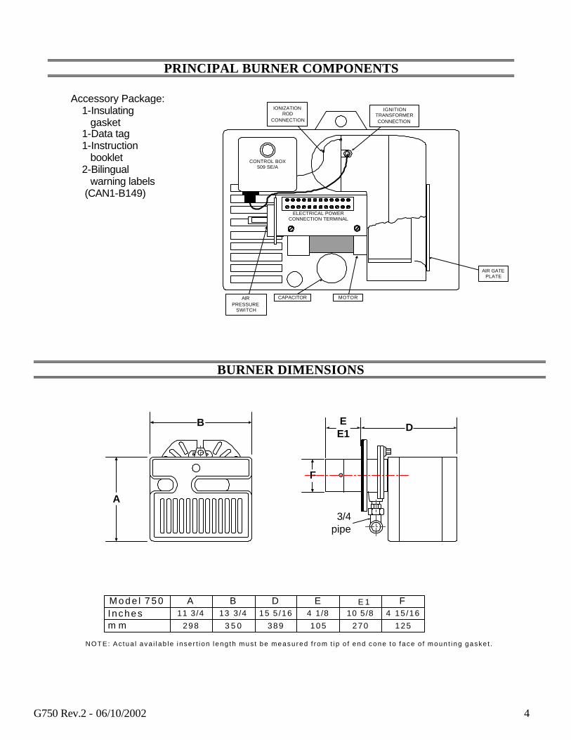
M o d e l 7 5 0Inchesm m
A11 3/4
298
B13 3/4
3 5 0
D15 5 /16
389
E4 1/8
105
10 5/8
270
F4 15 /16
125
NOTE: Ac tua l ava i l ab le i nse r t i on l eng th mus t be measu red f rom t i p o f end cone to f ace o f moun t i ng gaske t .
E 1
CONTROL BOX509 SE/A
CAPACITOR MOTOR
AIR GATEPLATE
AIRPRESSURE
SWITCH
ELECTRICAL POWERCONNECTION TERMINAL
IONIZATIONROD
CONNECTION
IGNITIONTRANSFORMERCONNECTION
PRINCIPAL BURNER COMPONENTS
BURNER DIMENSIONS
Accessory Package: 1-Insulating gasket 1-Data tag 1-Instruction booklet 2-Bilingual warning labels (CAN1-B149)

G750 Rev.2 - 06/10/2002 5
UNIVERSAL MOUNTING FLANGE DIMENSIONS
ELECTRODE AND FLAME PROBE ADJUSTMENTS
A B C D inches 1 1/2 1/4 7/16 2 7/8 mm 38 6 11 73
4 31/32-- 128mm
6 17 /32-- 166mm
8 1/4-- 210mm
9 1/4-- 235mm
7 7 / 8--
200
mm
2.0
3.7
Orifice
Propane adapter Propane orifice
Warning 2-3 mm
Ionization ProbeIgnition
electrode

G750 Rev.2 - 06/10/2002 1
1) GAS SUPPLY & FLOW DIRECTION OF GAS
2) GAS SUPPLY MAIN SHUTOFF MANUAL VALVE (FIELD SUPPLIED)
3) GAS SUPPLY PRESSURE TEST POINT (FIELD SUPPLIED)
4) GAS TRAIN PIPE DIAMETER SIZE(S):BURNER G750 3/4"BURNER G900 1" NPT (REDUCED AT COMBUSTION HEAD TO 3/4")
GAS SUPPLY PRESSURE RANGES:
NATURAL GAS PRESSURE:MIN. = 7.0" WCMAX. 14.0" WC
L.P. PROPANE GAS PRESSURE:MIN. = 8.0" WCMAX. 13.0" WC
9
FIELD SUPPLIED
1 2 3 5 6
RIELLO SUPPLIED
74
Ø
NOTE: ITEMS 5,6 & 7 COMBINATION GAS VALVE(S) ASSEMBLIES MAY BE UTILIZED WHERE APPROVED.
5) GAS APPLIANCE PRESSURE REGULATOR
6) SAFETY SHUTOFF GAS VALVE (VS) 120VOPERATED
7) MAIN GAS VALVE 120V OPERATEDBURNER G750 = SINGLE STAGE V1 ONLYBURNER G900 = TWO STAGE V1 & V2
8) FIRING VALVE MANUAL SHUTOFF
9) GAS BURNER MANIFOLD TEST POINT
GAS TRAIN LEGEND
SEE GASSUPPLYRANGE
8
TYPICAL GAS TRAIN LAYOUT
This gas train scope of supply meets the minimum controls requirements according to CGA and AGA regulations. Any additional requirements needed to meet local codes are the responsibility of others.

G750 Rev.2 - 06/10/2002 1
INSTALLING THE BURNER
1. Burner Chassis 2. Lock-nut 3. Burner Mounting Gasket 4. Insulation on Mounting Plate 5. Combustion Chamber 6. Forced Air Heat Exchanger 7. Burner Hinge Assembly 8. Gas Train Supply
Separate the combustion head of the burner from the chassis (1) by removing the lock-nut (2). Install the combustion head into the appliance. NOTE: Unless other else noted, it is recommended that the combustion head do not protrude into the combustion chamber.
Use this checklist prior to installation:
1) Check the input/output requirements of the boiler/furnace. 2) Check the physical size of the combustion chamber against the thermal
Requirements of the application and relate this to the sizing charts. 3) Check that there is sufficient air for proper combustion and adequate ventilation.
Local codes should be followed. Check that you have adequate space for servicing the equipment. Riello Burner requires a minimum of 13 inches clear space behind the red cover. This is required to allow easy removal of the cover for servicing and periodic maintenance.
4) Check that the chimney is of sufficient area to handle the exhaust gases. Make sure that the chimney is clear and there are not obstructions.
5) Barometric draft regulators, when used, should be of the double acting type, and Must be installed in accordance with the draft regulator Manufacturer’s instructions. Single acting barometric dampers are not permitted.
6) Affix the supplied operating instructions label to the burner. This label reads As follows: TO START THE BURNER: Switch on power, open manual gas cocks, set the thermostat above ambient temperature. If the burner does not start, Press the illuminated re-set button on the burner safety control. TO SHUT DOWN BURNER: Switch off power supply. If burner is switched off for extended periods, close manual gas cocks.
IMPORTANT: The installer must identify the main electrical power switch and manual gas shut off valve, for emergency conditions. The red cover on the burner must be in place and secured before the burner is placed in operation.
GENERAL INFORMATION Your Riello gas burner comes to you completely assembled and wired, ready for installation. The short head version has a fixed flange, which bolts directly to the front of the boiler/furnace. The long head version is equipped with a universal flange, which, when bolted to the boiler/furnace, allows the burner to be adjusted inwards or outwards for exact positioning in the combustion zone.
87
1
23
6
4 5

G750 Rev.2 - 06/10/2002 2
STEP-BY-STEP PROCEDURE 1) Remove the burner from the carton, taking care not to lose any of the supplied accessories, and check for
signs of physical damage. 2) Bolt the burner to furnace/boiler. Be sure to install the supplied mounting gasket. Ensure that the burner
is level and that the combustion head is centered in the boiler/furnace port. A spirit level placed across the cover will give you a good level. Refer to page 7 for position of combustion head relative to the chamber.
3) Check that the gas train is tight and make your connections to the incoming gas supply. a) A sediment trap must be provide at the gas connection inlet to the burner gas
train. b) If not already installed, a manual shutoff valve must be supplied. This valve must be upstream of
the burner/supply connection. c) A 1/8 NPT plugged tapping must be installed immediately upstream of the
Burner/supply connections and must be accessible for a test gauge. d) If required by local codes, provide gas vent lines at the gas regulators and
And valve (Riello gas trains are equipped with vent limiting orifices).
NOTE: Details of sediment trap, manual gas valve and test point can be found in installation of sediment trap and burner supply section.
4) Remove the red protective cover by removing the three screws. Make your adjustment of stop gate, (refer to firing rate specifications and settings charts for details). Replace and secure the air cover plate.
5) Electrical hookup: 120Volt 60 Hz incoming power lines should be connected to Terminals 1 and 2 on burner terminal block. A manual disconnect switch must be installed in the incoming power lines. Incoming power lines must be rigid conduit or flexible approved cable.
CAUTION: The hot wire must be connected to the black lead of the relay: neutral to the white lead. Do not reverse the polarity. The burner will not operate with the Phase/Neutral reversed, and the control box may be damaged. Proper earth ground should be connected to the terminal block mounting plate which should be a solid green wire to Earth Ground.
6) Start and check the burner functions as follows: a) Make a final check on the gas and electrical connections. b) Check that all adjustments have been completed c) Loosen the screw in the manifold gas test point and install a manometer. d) Switch on power. e) Set the thermostat at its highest setting and press the burner reset button. Allow the burner to run
through a complete cycle to check control functions. f) Turn on the manual gas valve and reset the safety. At this stage, the burner will open the air shutter
and once it is open, the burner will prepurge for aprox.30 seconds. Allow about 66 seconds for the control module to check all the operating circuits.
It may be necessary to repeat the starting cycle several times to free the gas train of entrapped air. If the burner goes to lockout, reset the safety button.
7) With the burner running and flame established, check the manifold gas pressure. Adjust manifold pressure to the correct value for the selected firing rate specified in the FIRING RATE SPECIFICATIONS AND SETTINGS chart. After completing the setting, remove the manometer and tighten the screws.
NOTE: Do not assume the burner is operating at optimum performance. A COMBUSTION TEST MUST BE PERFORMED

G750 Rev.2 - 06/10/2002 3
8) Make your final combustion efficiency test and fine tune the fan air damper as necessary. Replace the red protective cover and secure with three screws.
NOTE: Do not assume the burner is operating at optimum performance. 9) If the burner is installed on a central warm air furnace, affix the supplied warning labels to the furnace fan
cover door (inside and outside). 10) Always do a final set up by checking the gas flow rate by clocking the meter. Do a complete combustion
check with proper test equipment to obtain the best and safe CO² , O², and CO results. This test must be done by a qualified technician. The maximum CO² level for Natural Gas is 10%.
The maximum CO² level for Propane Gas is 12%. The recommended flue gas temperature is from 350 degrees Fahrenheit to 550 degrees Fahrenheit. Fill out the installation data on the label described below and explain the burner’s essential functions (starting and stopping) to the owner. Do not forget to give the dealer or service company’s name and address. NOTE: This label is supplied in the package with the burner and should be filled out and affixed to the appliance when the conversion burner is installed.
COMBUSTION HEAD SETTING COMBUSTION HEAD ADJUSTMENTS To set combustion head, loosen the Allen screw (A) and move the elbow (B) so that the rear edge of the air tube (C) coincides with the set point number (D). See firing rate chart for set points. Retighten the Allen screw (A).

G750 Rev.2 - 06/10/2002 4
FIRING RATE SPECIFICATIONS AND SETTINGS
Make sure you are using the correct table for either Natural gas or Propane gas.
Natural gas burner setup chart
BTU Input Air Gate Stop Gate Manifold Pressure Line Pressure 250,000 1.7 0.0 1.4” w.c. 8.0”w.c. 350,000 1.6 0.0 1.6” w.c. 8.0”w.c. 450,000 1.8 1.0 1.5” w.c. 8.0”w.c. 550,000 2.2 2.0 1.4” w.c. 8.0”w.c. 650,000 2.8 3.0 1.8” w.c. 10.0”w.c. 750,000 3.5 4.0 2.1” w.c. 12.0”w.c.
Line pressure measured at gas valve with burner firing.
Propane gas burner setup chart
BTU Input Air Gate Stop Gate Manifold Pressure Line Pressure 250,000 2.0 0.0 1.0” w.c. 11.0”w.c. 350,000 2.1 0.0 1.4” w.c. 11.0”w.c. 450,000 3.0 1.0 1.5” w.c. 11.0”w.c. 550,000 3.2 2.0 2.1” w.c. 11.0”w.c. 650,000 3.7 3.0 2.6” w.c. 11.0”w.c. 750,000 4.1 4.0 3.0” w.c. 11.0”w.c.
Line pressure measured at gas valve with burner firing.
NOTE: The above settings are a starting point for adjustments ONLY; a qualified gas technician using proper test equipment must do the final adjustments. Proper CO², 0², and CO readings must be taken and be within regulating code requirements.
All the settings above are based on zero (0) over fire-draft. If positive or negative chamber conditions exist some settings changes made be required. NOTE: For any referral to valve setting, please check the attached manufacturer valve specification.
WORKING RANGE OF BURNER
Example (shown above): With the gas burner installed on a boiler with an over-fire pressure of 1” water column in the combustion zone with the burner firing, the maximum output of the burner will be 615,000
100 120 180160140 240220200 260 2808060
205 410311273 819751685615546472 955888
50
170
KW/H
KBTU/H
0.2
0.4
0.6
0.8
1.0
1.2
1.6
1.4
In/wc
PR
ES
SU
RE
INPUT

G750 Rev.2 - 06/10/2002 5
BTU. If the input of the boiler is larger than the burner capacity in this condition, then the burner is not compatible to the job application.
COMBUSTION CHAMBER SIZING RECOMMENDED MINIMUM SIZES
NOTES: 1) Sizes shown above are for cylindrical or wet base boilers, or air cooled heat exchangers. 2) To size the chamber in applications other than wet base boilers, you must calculate area in square inches
of the combustion zone required to give you a grate area or floor area to match the BTU inputs according to local authority.
3) Recommended firebrick or cerafelt material has a continuous run limited to 2400 degrees Fahrenheit and a melting point of 3000 degrees Fahrenheit.
COMBUSTION CHECKS
CO²: It is advisable not to exceed a measured reading of 10% CO² for Natural Gas or 12% CO² for Propane Gas taken with the burner cover in place, to avoid the risk of the formation of CO due to minor changes in wind/draft conditions which may occur. CO: For safety reasons, the value of .02% (200 ppm) free air sample must not be exceeded.
IONIZATION CURRENT The minimum amount of current necessary for the control module to operate properly is 5 micro-amps. To measure the ionization current, unplug the connector fitted to the red wire and insert a DC micro ammeter in series with control box Terminal 2 and the ionization probe in which senses the flame. Refer to the drawing below.
20
24
28
32
36
40
16
LEN
GTH
280 440 760600 1000920
INPUT (000 BTUH)
MINIMUMDIAMETER16 inches

G750 Rev.2 - 06/10/2002 6
BURNER START-UP CYCLES
Lockout occurs immediately after flame failure. MAXIMUM LOADS TECHNICAL DATA Motor terminal 10 3A Voltage 120V +10% -15% Ignition transformer terminal 14 2A Frequency 60 Hz Valves terminal 12 – 13 2A Absorption 10 VA Lockout Lamp terminal 4 1A Prepurge time 55 seconds Ignition time 4.5 seconds Trial for ignition time 5 seconds Flame response time < 1 second Total start time 90 seconds Flame detector sensitivity 3 micro-amps Rated ionization current 5 micro-amps Electrical protection IP 40 Ambient temperature -20? to +60?C Maximum Fuse (external) 15 A (250V)
BURNER TECHNICAL DATA
Cal l for heat
Motor
Igni t ion t ransformer
Gas va lve open ing
F l a m e
Lock ou t
5 secondssel f d iagnost ics
55 secondsPrepurge
< 5 s e c o n d s
Cal l for heat
Motor
Igni t ion t ransformer
Gas va lve open ing
F l a m e
Lock ou t
5 secondssel f d iagnost ics
< 5 s e c o n d s
Normal
Lockout due to f lame fai lure
depend ing onheat load
55 second p repurge
G750 Rev.2 - 06/10/2002 7
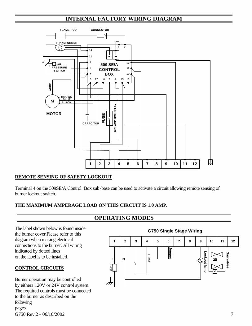
INTERNAL FACTORY WIRING DIAGRAM
REMOTE SENSING OF SAFETY LOCKOUT Terminal 4 on the 509SE/A Control Box sub-base can be used to activate a circuit allowing remote sensing of burner lockout switch. THE MAXIMUM AMPERAGE LOAD ON THIS CIRCUIT IS 1.0 AMP.
OPERATING MODES
The label shown below is found inside the burner cover.Please refer to this diagram when making electrical connections to the burner. All wiring indicated by dotted lines on the label is to be installed. CONTROL CIRCUITS Burner operation may be controlled by eithera 120V or 24V control system. The required controls must be connected to the burner as described on the following pages.
Lo
ckou
t lamp
Jumper
Lim
it
G750 Single Stage Wiring
Fuse
Gas valves
1211109876
L
21 543
N ACvs
V1
14
11
4
A
B 15321 617
12
8
5 10
96
13
1 2 3 7654 98 121110
FLAME ROD
CAIR
PRESSURESWITCH
M
WH
ITE
BROWNBLUE
BLACK
CAPACITOR FUS
E
6.25
AM
P T
IME
DE
LAY
MOTOR
CONNECTOR
509 SE/ACONTROL
BOX
TRANSFORMER
G750 Rev.2 - 06/10/2002 8
Lo
ckou
t lamp
Jum
per
G750 Single Stage Wiring
Fu
se
VS
Gas valves
1211109876
L
21 543
N AC
24 VOLT RELAYTT
2W
3R
4B
V1
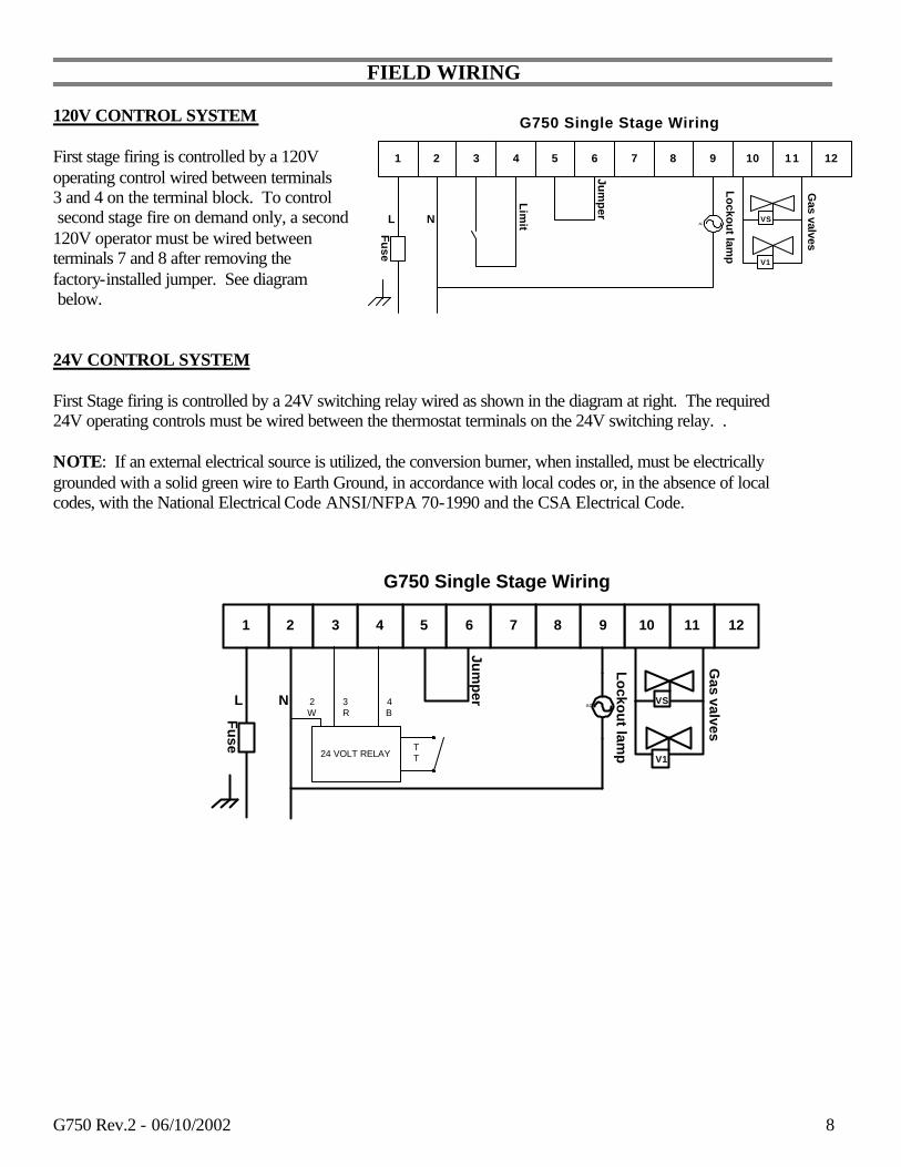
FIELD WIRING 120V CONTROL SYSTEM First stage firing is controlled by a 120V operating control wired between terminals 3 and 4 on the terminal block. To control second stage fire on demand only, a second 120V operator must be wired between terminals 7 and 8 after removing the factory-installed jumper. See diagram below. 24V CONTROL SYSTEM First Stage firing is controlled by a 24V switching relay wired as shown in the diagram at right. The required 24V operating controls must be wired between the thermostat terminals on the 24V switching relay. . NOTE: If an external electrical source is utilized, the conversion burner, when installed, must be electrically grounded with a solid green wire to Earth Ground, in accordance with local codes or, in the absence of local codes, with the National Electrical Code ANSI/NFPA 70-1990 and the CSA Electrical Code.
Lockout lamp
Jum
per
Lim
it
G750 Single Stage Wiring
Fu
se
VS
V1
Gas valves
1211109876
L
21 543
N AC

G750 Rev.2 - 06/10/2002 9
Gas piping supply should be installed according to local gas supplier authorities. PRESSURE TEST-OVER ½ PSIG. The appliance and its individual shutoff valve must be disconnected from the gas supply piping system during any pressure testing of the system at a test pressure in excess of ½ PSIG. PRESSURE TEST-1/2 PSIG OR LESS
The appliance must be isolated from the gas supply piping system by closing its individual manual shutoff valve during any testing of the gas supply piping system at test pressures equal to or less than ½ PSIG.
INSTALLATION OF SEDIMENT TRAP AND BURNER SUPPLY
union3/4" NPT
Burner gas train
Pipe Cap
NOT SUPPLIED

G750 Rev.2 - 06/10/2002 10
OPERATING FAULTS The integrated control system is self-checking. The cycle from start up to stability requires 66 seconds.
The burner will go into lockout under the following circumstances:
a) Flame failure b) The ionization probe is grounded c) Opening of the air pressure switch d) The burner shuts down if gas pressure switch (if used) opens because of insufficient gas pressure in
the supply lines.
During operation, if overheating occurs, shut off the manual gas valve to the appliance. Do NOT shut off the electric switch to the circulating pump or blower fan.
SHUT DOWN PROCEDURE Switch off electrical power to the unit. Close the manual supply gas valve.
START UP PROCEDURE Turn on electrical power to the unit, check operation. Turn on the manual gas supply valve. Check for leaks. Reset the burner safety control.
PROBLEM SOLVING GUIDE Burner starting difficulties and their causes:
1) The burner goes to lockout after the prepurge period because the flame does not ignite. a) Air has not been fully evacuated from the gas lines. b) The gas valve is passing too little gas. c) The ignition spark is irregular or not present. d) The gas valve is defective.
2) The burner does not start when there is a call for heat.
a) The air pressure switch has failed to return to n.c. contacts. b) There is no gas, or insufficient pressure in the supply lines to activate the optional gas pressure
switch (if used). c) There is a blown buss fuse behind the terminal strip. d) The burner has gone off on safety. e) The low voltage contacts or the low voltage relay are defective.
3) The burner does not go through prepurge, ignition is established, the burner fires for 2 seconds, then goes to lockout.
a) The air pressure switch does not change from normally closed to normally open contacts. This condition exists due to insufficient pressure in the air tube. Moving the firing head towards zero (0) on the stop gate will rectify this problem.
4) The burner goes through prepurge, ignition is established, the burner fires for 2 seconds, then goes to lockout.
a) The flame rectification rod (flame rod) has shorted to ground or is defective. b) Polarity is reversed or the earth ground is not properly connected. c) The ionization current is weak (lower than 5 micro-amps). d) here is interference from the ignition transformer. To correct this problem, reverse the primary
leads #14 and #16 in the control box sub-base.

G750 Rev.2 - 06/10/2002 11
SAFETY LOCKOUT This burner is equipped with multiple interlocking safety devices. In the event of a failure in the flame, or any blockage of the combustion air supply, the burner will “lock out” in a safety condition. In such an event, an illuminated red button will show on the front of the red cover. To restart the burner, press the button once only. Should the burner return to the lock out condition, call a qualified service technician or your gas company for assistance. In the case of loss of pressure in the gas supply line, the burner will go off on safety. If supplied with an optional gas pressure switch (or field installed), the burner will simply switch off on low gas pressure, and start up again when the gas pressure returns to normal. NOTE: Keep the area around the burner free and clear of all combustible materials, gasoline and other flammable vapors and liquids. Do not allow any obstruction to the free flow of air to the burner.
MAINTENANCE Like all precision equipment, your burner will require periodic maintenance. At an interval of 2 months, you should:
1) If your boiler/furnace has an observation port, visually check the flame. 2) Check and clean the air intake louver to remove any buildup of fluff, dust, pet hair, etc.
For any maintenance or repairs over and above those listed, contact your service technician or gas company. THERE ARE NO OWNER SERVICEABLE PARTS INSIDE THE RED COVER. Once a year, you should have the burner checked as indicated below, by your local authorized Riello dealer.
1) Check burner distributor head and mixing plates. Clean if necessary. 2) Check ignition electrode. Clean or replace as necessary. 3) Check the flame sensor rod (ionization rod) for dirt or carbon buildup. 4) Check manifold gas pressure 5) Check all mixing adjustments. 6) Generally clean all exposed parts and components. 7) Repeat combustion tests.
RECOMMENDATION: Once a year you should have your burner checked as indicated above, by a qualified Service Technician. Your Riello 40 gas burner is only part of your heating system. Once every year you should also have the complete system checked and cleaned by a qualified Service Technician.
OWNER INFORMATION AND ROUTINE MAINTENANCE

G750 Rev.2 - 06/10/2002 12
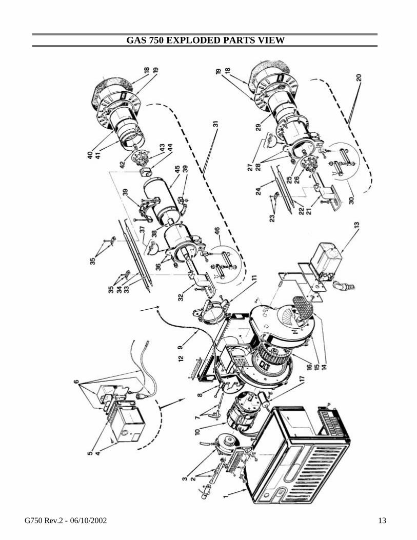
GAS 750 SPARE PART LIST
SPARE PARTS
GAS BURNER SYSTEM RIELLO 40 G750
REVISED: 10/01
NO
SPARE PARTS CODE
DESCRIPTION
NO
SPARE PARTS CODE
DESCRIPTION
1 3007522 Burner back cover 20 3950471 Short combustion head (280T1)
2 C7020002 Fuse 6.25A 21 3006697 Drawer assembly elbow
3 C7020008 Air Switch 22 3006706 Electrode assembly
4 3001163 Primary control Box 509S/E 23 3007265 Electrode and ionization clamp
5 3002256 Control Box Sub Base 24 3006709 Ionization assembly
6 3007948 Transformer - Ignition 25 3006703 Natural gas orifice
6A 3002461 Transformer-High Voltage Lead 26 3006700 Distributor head and mixing plate
7 3007288 Air Switch Tube & Connector 27 3005447 Gas test point
8 3007294 Air Plate Cover 28 3007525 Manifold
9 3007311 Ionization lead 29 3006694 End cone
10 3005845 Burner Motor 30 3000870 Hinge assembly
11 3006689 Chassis Mounting Collar 31 3950472 Long combustion head (280T2)
12 3007522 Chassis Front Plate 32 3006697 Drawer assembly elbow
13 3007523 Air Damper Motor G900 Only
33 3006962 Electrode assembly
14 3007421 Air Damper Plate G900 Only 34 3006961 Ionization assembly
14 3007206 Manual Air Shutter G750 35 3003409 Electrode & ionization clamp
15 3007211 Air Intake Housing 36 3007526 Manifold
16 3005799 Fan 37 3005447 Gas test point
17 3007307 Capacitor 20?F 38 3007313 Natural Gas Tube
18 3005852 Mounting gasket 39 3005849 Semi-flange 2 required
19 3005851 Universal mounting flange 40 3006694 End cone
41 3007283 Combustion Head Connector
42 3006703 Natural gas orifice
43 3006700 Distributor head and mixing plate
44 3007314 Electrode support
45 3007286 Air tube -long
47 3000870 Hinge assembly
G750 Rev.2 - 06/10/2002 13
GAS 750 EXPLODED PARTS VIEW

G750 Rev.2 - 06/10/2002 14
35 Pond Park Rd. Hingham, MA 02043 Phone: 781-749-8292
Toll Free: 800-992-7637 Fax: 781-740-2069
2165 Meadowpine Blvd. Mississauga,On L5H 3R2
Phone: 905-542-0303 Toll Free: 800-387-3898
Fax: 905-542-1525
BURNER START- UP FORM * Burner S/N. or
Model: Appliance:
Installer name:
Company: Installation
date:
Address:
Phone: Fax:
Owner Name:
Address:
Phone: E-mail:
Burner Start-up Info (OIL) Burner Start-up Info (GAS)
Nozzle Info: Gas Supply Pressure:
Pump Pressure: Pump
pressure:
Air Setting: Turbulator setting: Air Setting: Head Setting:
Draft Overfire: Draft
breech: Draft Overfire: Draft
breech:
CO2: CO: O2:
CO2: CO: O2:
Smoke density: (Bacharach) Manifold pressure:
Single Line:
Two Lines:
Ionization Reading
(µAd.c.): Input
BTU/Hr:
* This form was designed and provided in the installation manual for reference and also for providing technical information, which can be faxed or mailed to our technical hot-line coordinator when technical assistance is required. Please complete this form, fax it or mail it at the address/fax above, or send an e-mail with the information listed below to: [email protected]

G750 Rev.2 - 06/10/2002 15
35 Pond Park Road Hingham, MA 02043 Phone 781-749-8292
Toll Free 800-992-7637 Fax 781-740-2069
www.riellousa.com
2165 Meadowpine Blvd Mississauga, ON L5N 6H6 Phone 905-542-0303 Toll Free 800-387-3898 Fax 905-542-1525 www.riellocanada.com
Technical Support Hotline 1-800-4-RIELLO
1-800-474-3556