installation instruction oil fired warm air furnace
TRANSCRIPT
CONTENTS
GENERAL . . . . . . . . . . . . . . . . . . . . . . . . . . . . . . . . . . . . . 2NOMENCLATURE . . . . . . . . . . . . . . . . . . . . . . . . . . . 2SAFETY . . . . . . . . . . . . . . . . . . . . . . . . . . . . . . . . . . . 2INSPECTION . . . . . . . . . . . . . . . . . . . . . . . . . . . . . . . 2LIMITATIONS . . . . . . . . . . . . . . . . . . . . . . . . . . . . . . . 2
LOCATION . . . . . . . . . . . . . . . . . . . . . . . . . . . . . . . . . . . . 3GROUND INSTALLATION . . . . . . . . . . . . . . . . . . . . . 3ROOF INSTALLATION . . . . . . . . . . . . . . . . . . . . . . . . 3
UNIT PLACEMENT . . . . . . . . . . . . . . . . . . . . . . . . . . . . . . 3VERIFY INDOOR REFRIGERANT ORIFICE . . . . . . . 4INSTALLATIONS REQUIRING TXV . . . . . . . . . . . . . 4
PIPING CONNECTIONS . . . . . . . . . . . . . . . . . . . . . . . . . . 5PRECAUTIONS DURING LINE INSTALLATION . . . . 5PRECAUTIONS DURING BRAZING OF LINES. . . . . 6PRECAUTIONS DURING BRAZING ANGLE VALVE . . . . . . . . . . . . . . . . . . . . . . . . . . 6 & 7
GENERAL INFORMATION & GROUNDING . . . . . . . . . . 8
FIELD CONNECTIONS POWER WIRING . . . . . . . . . . . . 8
FIELD CONNECTIONS CONTROL WIRING . . . . . . . . . . 8SYSTEM CHARGE . . . . . . . . . . . . . . . . . . . . . . . . . . 8MEASUREMENT METHOD . . . . . . . . . . . . . . . . . . . . 9SUPERHEAT CHARGING METHOD . . . . . . . . . . . . 9
SYSTEM START-UP . . . . . . . . . . . . . . . . . . . . . . . . . . . . . 9ENERGIZE CRANKCASE HEATER . . . . . . . . . . . . . 9SYSTEM CONTROLLER - HDB076 ONLY . . . . . . . 13INSTRUCTING THE OWNER. . . . . . . . . . . . . . . . . . 13INDICATIONS OF PROPER OPERATION . . . . . . . 13MAINTENANCE . . . . . . . . . . . . . . . . . . . . . . . . . . . . 13
INSTALLATION INSTRUCTION
CAUTION: READ ALL SAFETY GUIDES BEFORE YOU BEGIN TO INSTALL YOUR UNIT.
SAVE THIS MANUAL
OIL FIRED WARM AIR FURNACE
P-HMX12F05701 - P-HMX12F08001
Horizontal or Up-Flow Model
P-HMX14F10001 - P-HMX20F12001
(UPFLOW ONLY)
ALL INSTALLATIONS MUST MEET ALL LOCAL, PROVINCIAL/STATE, AND FEDERAL CODES WHICH MAY DIFFER FROM THIS MANUAL
Read this complete manual before beginning installation. Theseinstructions must be kept with the furnace for future reference.
) 035-17473-000 Rev. A (900)

035-17473-000 Rev. A (900))
2 Unitary Products Group
IMPROPER INSTALLATION MAY CREATE A CON-DITION WHERE THE OPERATION OF THE PROD-UCT COULD CAUSE PERSONAL INJURY OR PROPERTY DAMAGE.
IMPROPER INSTALLATION, ADJUSTMENT, ALTERATION, SERVICE OR MAINTENANCE CAN CAUSE INJURY OR PROPERTY DAMAGE. REFER TO THIS MANUAL FOR ASSISTANCE OR ADDI-TIONAL INFORMATION, CONSULT A QUALIFIED INSTALLER, SERVICE AGENCY OR THE GAS SUPPLIER.
THIS PRODUCT MUST BE INSTALLED IN STRICT COMPLIANCE WITH THE ENCLOSED INSTALLA-TION INSTRUCTIONS AND ANY APPLICABLE LOCAL, STATE, AND NATIONAL CODES INCLUD-ING BUT NOT LIMITED TO, BUILDING, ELECTRI-CAL AND MECHANICAL CODES.
The furnace area must not be used as a broom closetor for any other storage purposes, as a fire hazard baybe created. Never store items such as the followingon, near or in contact with the furnace.
1.Spray or aerosol cans, rags, brooms, dust mops, vac-uum cleaners or other cleaning tools.
2.Soap powders, bleaches, waxes or other cleaningcompounds; plastic items or containers; gasoline,kerosene, cigarette lighter fluid, dry cleaning fluidsor other volatile fluid.
3.Paint thinners and other painting compounds.
4.Paper bags, boxes or other paper products
Never operate the furnace with the blower doorremoved. To do so could result in serious personalinjury and/or equipment damage.
CONTENTS
GENERAL INFORMATION 3
DESCRIPTION 3
INSPECTION 3
NOTES, CAUTIONS & WARNINGS 3
LIMITATIONS AND LOCATION 3
Clearances to Combustibles 4
UNIT INSTALLATION 4
COMBUSTION AIR 4
unit clearances to combustibles 4
estimated free area 5
upflow/horizontal raitings &
physical / electrical data 6
ratings & physical/electrical data 7
VENTING 8
CATEGORY I VERTICAL VENTING 8
CATEGORY 1 - 450 F. MAX. VENT TEMP. 8
HORIZONTAL SIDEWALL VENTING 8
VENT SAFETY CHECK PROCEDURE 8
DUCTWORK 9
upflow/horizontal models - upflow application 9
FILTERS INSTALLATION - (UPFLOW/HORIZONTAL)9
upflow/horizontal models 11
horizontal application 11
ATTIC INSTALLATION 11
CRAWL SPACE INSTALLATION 11
downflow model application 12

DOWNFLOW FILTERS 12
SUPPLY AIR DUCTS 13
GAS PIPING 13
ELECTRICAL POWER CONNECTION 14
ELECTRICAL CONTROL CONNECTIONS 15
SAFETY CONTROLS 15
START-UP AND ADJUSTMENTS 16
IGNITION SYSTEM CHECKOUT/ADJUSTMENT 16
CHECKING GAS INPUT 16
gas rate (cubic feet per hour) 17
ADJUSTMENT OF MANIFOLD GAS PRESSURE 17
ADJUSTMENT OF TEMPERATURE RISE 18
ADJUSTMENT OF FAN-OFF CONTROL SETTINGS18
ACCESSORY CONNECTIONS 19
BLOWER PERFORMANCE CFM - UP/HORiz 20
FILTER PERFORMANCE 21
BLOWER PERFORMANCE CFM - DOWNFLOW 21
FILTER PERFORMANCE - Pressure Drop 21
APPLYING FILTER PRESSURE DROP TO DETER-MINE
SYSTEM AIRFLOW 22
OPERATION AND MAINTENANCE 22
SEQUENCE OF OPERATION 22
HEATING CYCLE 22
MAINTENANCE 23
BLOWER CARE 24
Cleaning the Heat Exchanger 24
TROUBLESHOOTING 25
FURNACE CONTROL DIAGNOSTICS 25
WIRING DIAGRAM - UPFLOW/HORIZONTAL 28
WIRING DIAGRAM - downflow 29
035-17473-000 Rev. A (900)
4 Unitary Products Group
INTRODUCTION
Please read these instructions completely and carefullybefore installing and operating the furnace.
The furnace must be installed and set up by a qualifiedcontractor.
model
P-HMX12F05701 and P-HMX12F08001 are oil firedforced air multi-positional furnaaces, with an outputcapacity range of 58,000 BTU/Hr to 79,000 BTU/HR.These furnaces may be installed in the up-flow posi-tion, s well as both horizontal positions.
P-HMX14F10001 and P-HMX20F12001 are oil fired____ Up Flow ONLY furnaces, with an output capacityrange of 100,000 BTU/Hr. to 120,000 BTU/Hr. Thesefurnaces shall be installed in the up-flow position only.
All model furnaces are listed with the Canadian Stan-dards Association, (CSA) and comply with bothCanadian and American (U.S.) standards for use withNo. 1 (Stove) and No. 2 (Furnace) Oil. Please refer tothe tables in the appendix for performance and dimen-sional data.
In Canada, the installation of the furnace and relatedequipment shall be installed in accordance with theregulations of CAN/CSA - B139-M91, InstallationCode For Oil Burning Equipment, as well as inaccordance with local codes.
In the United States of America, the installation of thefurnace and related equipment shall be installed inaccordance with the regulations of NFPA No. 31,Installation of Oil Burning Equipment, as well as inaccordance with local codes.
When installation or application questions arise, regu-lations prescribed in the National Codes and LocalRegulations take precedence over the general instruc-tions provided with this installation manual. When indoubt, please consult your local authorities.
All models are shipped assembled and pre-wired. Thefurnace should be carefully inspected for damagewhen being unpacked.
HEAT LOSS
The maximum hourly heat loss for each heated spaceshall be calculated in accordance with the proceduresdescribed in the manuals of the Heating, Refrigera-tion and Air Conditioning Institute of Canada(HRAI), or by any other method which is suitable forlocal conditions, provided the results obtained are insubstantial agreement with, and not less than thoseobtained using the procedure described in their manu-als.
In the United States, Manual J. titled, "Load Calcula-tion" published by the Air Conditioning Contractorsof America, describes a suitable procedure for calcu-lating the maximum hourly heat loss.
location of unit
The furnace should be located such that the flue con-nection to the chimney is short, direct and consists ofas few elbows as possible. When possible, the unitshould be centralized with respect to the supply andreturn air duct work. A central location minimizes thetrunk duct sizing. All models may be installed on com-bustible floors.
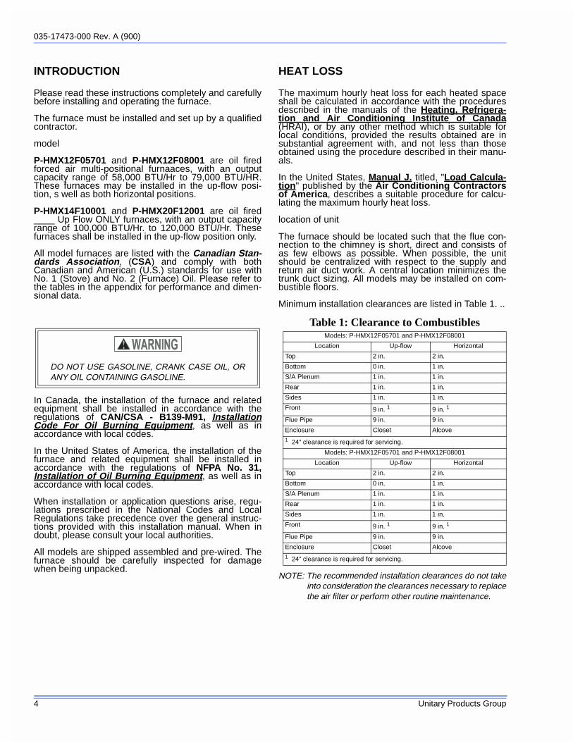
Minimum installation clearances are listed in Table 1. ..
NOTE: The recommended installation clearances do not takeinto consideration the clearances necessary to replacethe air filter or perform other routine maintenance.
DO NOT USE GASOLINE, CRANK CASE OIL, ORANY OIL CONTAINING GASOLINE.
Table 1: Clearance to CombustiblesModels: P-HMX12F05701 and P-HMX12F08001
Location Up-flow Horizontal
Top 2 in. 2 in.
Bottom 0 in. 1 in.
S/A Plenum 1 in. 1 in.
Rear 1 in. 1 in.
Sides 1 in. 1 in.
Front 9 in. 1 9 in. 1
Flue Pipe 9 in. 9 in.
Enclosure Closet Alcove
1 24” clearance is required for servicing.
Models: P-HMX12F05701 and P-HMX12F08001
Location Up-flow Horizontal
Top 2 in. 2 in.
Bottom 0 in. 1 in.
S/A Plenum 1 in. 1 in.
Rear 1 in. 1 in.
Sides 1 in. 1 in.
Front 9 in. 1 9 in. 1
Flue Pipe 9 in. 9 in.
Enclosure Closet Alcove1 24” clearance is required for servicing.
035-17473-000 Rev. A (900)
Unitary Products Group 5
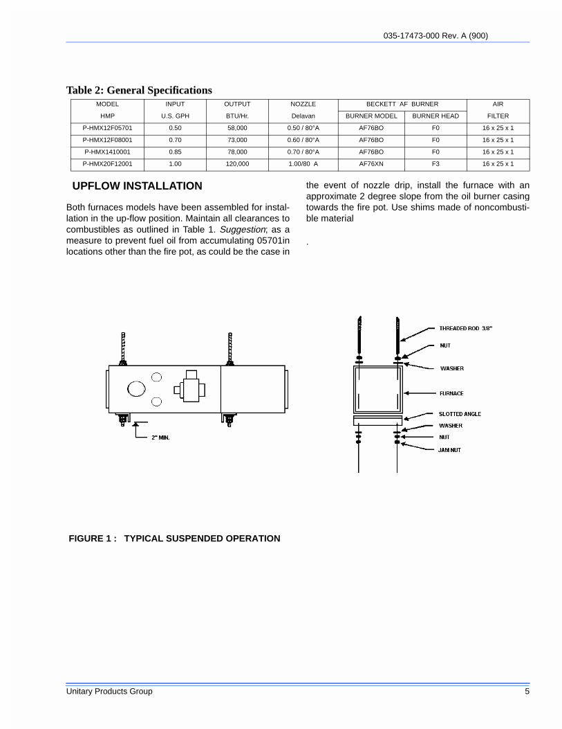
UPFLOW INSTALLATION
Both furnaces models have been assembled for instal-lation in the up-flow position. Maintain all clearances tocombustibles as outlined in Table 1. Suggestion; as ameasure to prevent fuel oil from accumulating 05701inlocations other than the fire pot, as could be the case in
the event of nozzle drip, install the furnace with anapproximate 2 degree slope from the oil burner casingtowards the fire pot. Use shims made of noncombusti-ble material
.
Table 2: General SpecificationsMODEL INPUT OUTPUT NOZZLE BECKETT AF BURNER AIR
HMP U.S. GPH BTU/Hr. Delavan BURNER MODEL BURNER HEAD FILTER
P-HMX12F05701 0.50 58,000 0.50 / 80°A AF76BO F0 16 x 25 x 1
P-HMX12F08001 0.70 73,000 0.60 / 80°A AF76BO F0 16 x 25 x 1
P-HMX1410001 0.85 78,000 0.70 / 80°A AF76BO F0 16 x 25 x 1
P-HMX20F12001 1.00 120,000 1.00/80 A AF76XN F3 16 x 25 x 1
FIGURE 1 : TYPICAL SUSPENDED OPERATION

035-17473-000 Rev. A (900)
6 Unitary Products Group
HORIZONTAL INSTALLATION
The 057 & 080 BTU output model furnaces are assem-bled and shipped ready for installation in the up-flowposition. The furnace may be installed in either of thehorizontal positions; warm air discharging left or warmair discharging right by following these steps:
1. Rotate the furnace 90° to the desired position.
2. Remove the three nut and washer sets fastening the oilburner assembly to the furnace. Rotate the oil burnerassembly to be in the upright position. (Ignition trans-former and / or oil primary control control should be ontop).
3. Re-align the oil burner assembly to the combustionchamber (fire-pot), then secure into place with the threenut and washer sets.
NON-SUSPENDED INSTALLATION
Maintain clearances to combustibles as outlined inTable 1. Installation on a combustible floor requires aclearance of 1 inch. This can be done by using non-combustible materials such as one inch thick channeliron or similar material. The furnace must be supportedin such a way as to not allow twisting or sagging of thecabinet. Suggestion; as a measure to prevent fuel oilfrom accumulating in locations other than the fire pot,as could be the case in the event of nozzle drip, installthe furnace with an approximate 2 degree slope fromthe oil burner casing towards the fire pot. Use shimsmade of noncombustible material.
SUSPENDED INSTALLATION
Refer to Figure 1. Maintain clearances to combustiblesas outlined in Table 1. Remove the four circular knock-outs on the top panel, and similarly, the four circularknock-outs on the bottom panel. The removed knock-outs allow 3/8 inch treaded road to be inserted throughthe interior of the furnace. Use care when insertingrods, since the foil backed insulation can be easilyripped and torn away from the panel surfaces. Securethe furnace with 2 inch minimum slotted angle or equiv-alent, as shown in Figure 4. The furnace must be sup-ported in such a way as to not allow twisting or saggingof the cabinet. Suggestion; as a measure to preventfuel oil from accumulating in locations other than thefire pot, as could be the case in the event of nozzledrip, install the furnace with an approximate 2 degreeslope from the oil burner casing towards the fire pot.
AIR CONDITIONING APPLICATIONS
If the furnace is used in conjunction with air condition-ing, the furnace shall be installed in parallel with orupstream from the evaporator coil to avoid condensa-tion in the heat exchanger. In a parallel installation, thedampers or air controlling means must prevent chilledair from entering the furnace. If the dampers are manu-ally operated, there must be a means of control to pre-vent the operation of either system unless the dampersare in the full heat or full cool position. The air heatedby the furnace shall not pass through a refrigerationunit unless the unit is specifically approved for suchservice.
The blower speed must be checked and adjusted tocompensate for the pressure drop caused by the evap-orator coil. Refer to Appendix B for recommended wir-ing and electrical connections of the air conditioningcontrols.
COMBUSTION AIR
If the furnace is installed in a closet or utility room, twoopenings must be provided connecting to a well venti-lated space (full basement, living room or other roomopening thereto, but not a bedroom or bathroom). Oneopening shall be located above the level of the uppervent opening and one opening below the combustionair inlet opening in the front of the furnace. Each open-ing shall have a minimum free area of 1½ squareinches per 1,000 Btu/h of total input rating of all appli-ances installed in the room.
For furnaces located in buildings of unusually tight con-struction, such as those with high quality weather strip-ping, caulking, windows and doors, or storm sashedwindows, or where basement windows are well sealed,a permanent opening communicating with a well venti-lated attic or with the outdoors shall be provided, usinga duct if necessary. The duct opening shall have a freearea of 1½ square inches per 1,000 Btu/h of total inputrating of all appliances to be installed. When a furnaceis installed in a full basement, infiltration is normallyadequate to provide air for combustion and draft opera-tion. Furnace rooms under 65m³ (700 ft³) should auto-matically be treated as confined space.
CHIMNEY VENTING
The chimney must be sized correctly and be in goodrepair. If the chimney is oversized, there is a high riskof the flue gases condensing resulting in damage to thechimney and other venting parts. This problem may be

035-17473-000 Rev. A (900)
Unitary Products Group 7
corrected by the use of an appropriately sized chimneyliner.
If the chimney serves the furnace only, the vent shouldbe sized at 4 inch minimum, 5 inch maximum. Thetable below is based on dedicated venting. If the fur-nace is to be co-vented with other appliances, refer toCAN/CSA B139, Installation Code For Oil BurningEquipment or NFPA 31, Standard for the Installation ofOil Burning Equipment and NFPA 211, Standard forChimneys, Fireplaces, Vents, and Solid Fuel-BurningAppliances for correct sizing information.
IMPORTANT: The chimney must be capable of provid-ing sufficient draft at all times for the safe removal ofthe products of combustion.
The chimney should be tested under “winter” condi-tions; doors and windows closed, all other fossil fuelburning appliances on, clothes dryer on, bathroom fanson, etc. If the chimney cannot overcome the competi-tion for air, it will be necessary to access the reason for
it, and take corrective action. If the chimney is found tobe sized correctly and in good repair, it will probably benecessary to re-evaluate the availability of combustionand ventilation air, and take corrective action.
NOTE: These furnaces are approved for use with L-Vent.
NOTE: Maximum Temperature for L-Vent is 575°F(300C).
The flue pipe should be as short as possible with hori-zontal pipes sloping upward toward the c himney at arate of one quarter inch to the foot. The flue pipeshould not be smaller in cross section area than the
Table 3: Min. Chimney Base Temperatures (°F)
Model Chimney Height (ft.)
11 20 28 36
Chimneys with Thermal Resistance less than R6
P-HMX12F05701 300 400 535 725
P-HMX12F08001 270 330 405 505
P-HMX14F10001 250 300 355 430
P-HMX12F12001 225 300 365 430
Chimneys with Thermal Resistance greater than R6
P-HMX12F5701 185 200 220 250
P-HMX12F08001 175 185 195 215
P-HMX14F10001 165 185 195 205
P-HMX12F12001 165 185 195 205
FIGURE 2 : COMMON CHIMNEY PROBLEMS
Table 4: Common Chimney ProblemsRefer to Figure 2
Key Trouble Diagnostic Remedy
A Top of chimney lower than surrounding
objects
Observation Extend chimney above all surround-ing objects within 30
feet.
B Chimney Cap or ven-tilator.
Observation Remove
C Coping restricts opening.
Observation Make opening as large as inside of
chimney.
Key Trouble Diagnostic Remedy
D Obstruction in chim-ney
Can be found by light and mirror reflecting conditions in chim-
ney.
Use weight to break and dislodge.
E Joist protruding into chimney.
Lowering a light on an extension cord.
Must be handled by competent masonry
contractor.
F Break in chimney lin-ing.
Smoke test - build smudge fire blocking
off other opening, watching for smoke
to escape.
Must be handled by competent masonry
contractor.
G Collection of soot at narrow space in flue
opening.
Lower light on exten-sion cord.
Clean out with weighted brush or bag of loose gravel
on end of line.
H Offset Lower light on exten-sion cord.
Change to straight or to long offset.
I Two or more open-ings to the same
chimney.
Found by inspection from basement.
The least important opening must be
closed, using some other chimney flue.
J Loose-seated pipe in flue opening.
Smoke test. Leaks should be eliminated by
cementing all pipe openings.
K Smoke pipe extends into chimney.
Measurement of pipe from within or obser-
vation of pipe by means of a lowered
light.
Length of pipe must be reduced to allow
end of pipe to be flush with inside of
tile.
L Failure to extend the length of flue parti-
tion to the floor.
By inspection or smoke test.
Extend partition to floor level.
M Loose-fitted clean-out door.
Smoke test. Close all leaks with cement.
035-17473-000 Rev. A (900)
8 Unitary Products Group
flue collar on the furnace. The flue pipe should connectto the chimney such that the flue pipe extends into, andterminates flush with the inside surface of the chimneyliner. Seal the join between the pipe and the lining. Thechimney outlet should be at least two feet above thehighest point of a peaked roof. All unused chimneyopenings should be closed. Chimneys must conform tolocal, provincial or state codes, or in the absence oflocal regulations, to the requirements of the NationalBuilding Code.
See Figure 2 and Table 3 for common chimney prob-lems and their remedies.
The flue pipe must not be routed through concealedspace, because it must be visually checked for signs ofdeterioration during the annual inspection and servic-ing. The flue pipe must not pass through any floor orceiling, but may pass through a wall where suitable fireprotection provisions have been installed. Refer to thelatest edition of CAN/CSA B-139 for rules governingthe installation of oil burning equipment. In the UnitedStates, refer to the latest edition of NFPA 31 for regula-tions governing the installation of oil burning equip-ment.
BAROMETRIC DAMPER CONTROL.
This device is used in conjunction with conventionalchimney venting. This control (or draft regulator) auto-matically maintains a constant negative pressure in thefurnace to obtain maximum efficiency. It ensures thatproper pressures are not exceeded. If the chimneydoes not develop sufficient draft, the draft control can-not function properly. The draft regulator, must beinstalled within the same room or enclosure as the fur-nace, and should not interfere with the combustion airsupplied to the burner. The control should be located aminimum of 3 diameters (18”) from the furnace breach-ing. and installed in accordance to the instructions sup-plied with the regulator. The flue outlet pressure(measured between the furnace and draft regulator)should be set to - 0.02 in. w.c.
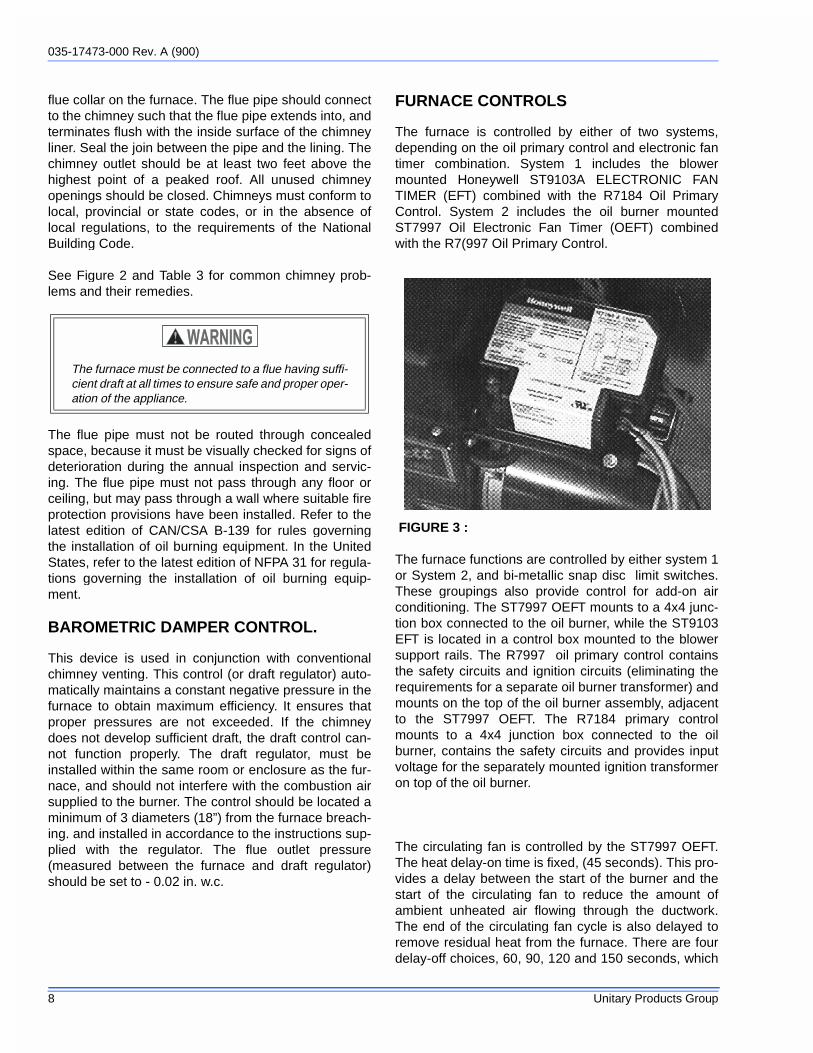
FURNACE CONTROLS
The furnace is controlled by either of two systems,depending on the oil primary control and electronic fantimer combination. System 1 includes the blowermounted Honeywell ST9103A ELECTRONIC FANTIMER (EFT) combined with the R7184 Oil PrimaryControl. System 2 includes the oil burner mountedST7997 Oil Electronic Fan Timer (OEFT) combinedwith the R7(997 Oil Primary Control.
The furnace functions are controlled by either system 1or System 2, and bi-metallic snap disc limit switches.These groupings also provide control for add-on airconditioning. The ST7997 OEFT mounts to a 4x4 junc-tion box connected to the oil burner, while the ST9103EFT is located in a control box mounted to the blowersupport rails. The R7997 oil primary control containsthe safety circuits and ignition circuits (eliminating therequirements for a separate oil burner transformer) andmounts on the top of the oil burner assembly, adjacentto the ST7997 OEFT. The R7184 primary controlmounts to a 4x4 junction box connected to the oilburner, contains the safety circuits and provides inputvoltage for the separately mounted ignition transformeron top of the oil burner.
The circulating fan is controlled by the ST7997 OEFT.The heat delay-on time is fixed, (45 seconds). This pro-vides a delay between the start of the burner and thestart of the circulating fan to reduce the amount ofambient unheated air flowing through the ductwork.The end of the circulating fan cycle is also delayed toremove residual heat from the furnace. There are fourdelay-off choices, 60, 90, 120 and 150 seconds, which
The furnace must be connected to a flue having suffi-cient draft at all times to ensure safe and proper oper-ation of the appliance.
FIGURE 3 :

035-17473-000 Rev. A (900)
Unitary Products Group 9
are field adjustable by manipulating the DIP switcheson the lower front of the ST7997 OEFT, or on theST9103 EFT Board.
The cooling delay-on and delay-off times are fixed at30 seconds each.
The furnace is protected against over-heating by fixedhigh temperature limits. These controls are factory setand are not field adjustable. If an over temperaturecondition is detected, one or both limit switches willinterrupt power to the oil primary control, which will shutoff the oil burner. The circulating fan will continue tooperate. The high limit switches will automatically resetwhen the furnace returns to a safe temperature.
ELECTRICAL CONNECTIONS
The furnace is listed by the Canadian StandardsAssociation (CSA). It is factory wired and requiresminimal field wiring. In Canada, all field wiring shouldconform to CAN/CSA C22.1 Canadian ElectricalCode, Part 1, and by local codes, where they prevail.In the United States, the wiring must be in accordancewith the National Fire Protection Association NFPA-70, National Electrical Code, and with local codesand regulations.
The furnace should be wired to a separate and dedi-cated circuit in the main electrical panel; however,accessory equipment such as electronic air cleanersand humidifiers may be included on the furnace circuit.Although a suitably located circuit breaker can be usedas a service switch, a separate service switch is advis-able. The service switch is necessary if reaching thecircuit breaker involves becoming close to the furnace,or if the furnace is located between the circuit breakerand the means of entry to the furnace room. The fur-nace switch (service switch) should be clearly marked,installed in an easily accessible area between the fur-nace and furnace room entry, and be located in such amanner to reduce the likelihood that it would be mis-taken as a light switch or similar device.
The power requirement for the P-HMX Series model is:120 VAC, 1 ∅ , 60 Hz., 12A.
Accessories requiring 120 VAC power sources such aselectronic air cleaners and humidifier transformers maybe powered from the ST7997 OEFT. Do not use thedirect drive motor connections as a power source,since there is a high risk of damaging the accessoriesby exposure to high voltage from the auto-generatingwindings of the direct drive motor.
Thermostat wiring connections and air conditioningcontactor low voltage connections are shown in the wir-ing diagram. Some micro-electronic thermostatsrequire additional controls and wiring. Refer to the ther-mostat manufacturer's instructions.
The thermostat should be located approximately 5 feetabove the floor, on an inside wall where there is goodnatural air circulation, and where the thermostat will beexposed to average room temperatures. Avoid loca-tions where the thermostat will be exposed to colddrafts, heat from nearby lamps and appliances, expo-sure to sunlight, heat from inside wall stacks, etc.
FIGURE 4 : ST9103A EFT
FIGURE 5 : R7997 OIL PRIMARY AND ST7997 OEFT
035-17473-000 Rev. A (900)
10 Unitary Products Group
For thermostats with heat anticipators, the heat antici-pator should be adjusted to the amperage draw of theheating control circuit as measured between the "R"and "W" terminals of the thermostat. To reduce the riskof damaging the heat anticipator, do not measure cir-cuit. To determine the heating circuit amperage draw:
1. Note and disconnect the wires from the “R” and “W” ther-mostat terminals.
2. Connect an ammeter between the two disconnectedwires from the thermostat.
3. Note the amperage reading.
4. Re-connect the thermostat wires. If the thermostat isserving a combination heating and air conditioning sys-tem, pay particular attention to polarity.
5. When the thermostat is reconnected and re-plumbed,adjust the heat anticipator setting to match the observedamperage reading.
HUMIDIFIER
A humidifier is an optional accessory available throughmost heating supplies outlets. Installation should becarried out in accordance with the humidifier manufac-turer's installation instructions. Water or water dropletsfrom the humidifier should not be allowed to come intocontact with the furnace heat exchanger. Terminals(115 v) are provided on the ST7997 OEFT control. Donot use direct drive motor connections as a source ofpower for 120 VAC humidifiers and humidifier trans-formers.
OIL TANK
Oil storage tanks must be selected and installed incompliance with applicable codes; in Canada, CAN/CSA-B139, Installation Code for Oil Burning Equip-ment, Section 6 and in the United States, NFPA 31,Standard for the Installation of Oil Burning Equipment,Chapter 2. Observe all local codes and by-laws.
In general, the oil tank must be properly supported andremain stable in both empty and full condition. The oiltank must be fitted with vent and supply pipes to theoutdoors. Refer to the above mentioned codes for siz-ing. The vent pipe must be no less than 1¼ inchesI.P.S., and terminate with an appropriate vent cap in alocation where it will not be blocked. The fill pipe mustbe no less than 2 inches I.P.S., and terminate with anappropriate cap in a location where debris will not enterthe fill pipe during oil delivery.
If located indoors, the tank should normally be in thelowest level, (cellar, basement, etc.). It must beequipped with a shut-off valve at the tank outlet usedfor the oil supply. The oil tank must be located as to notblock the furnace / room exit pathway. Observe allclearances specified in the above mentioned codes.
PIPING INSTALLATION
In Canada, the entire fuel system should be installed inaccordance with the requirements of CAN/CSA B-139,and local regulations. Use only approved fuel oil tankspiping, fittings and oil filters.
In the United States the installation must be in accor-dance with the requirements of NFPA No. 31 and localcodes and regulations.
Ensure that all fittings used in a copper oil line systemare high quality flare fittings. Do not use compressionfittings.
Pressurized or gravity feed installations must notexceed 10 PSIG on the inlet line or the return line at thepump. A pressure greater than 10 PSIG may causedamage to the shaft seal.
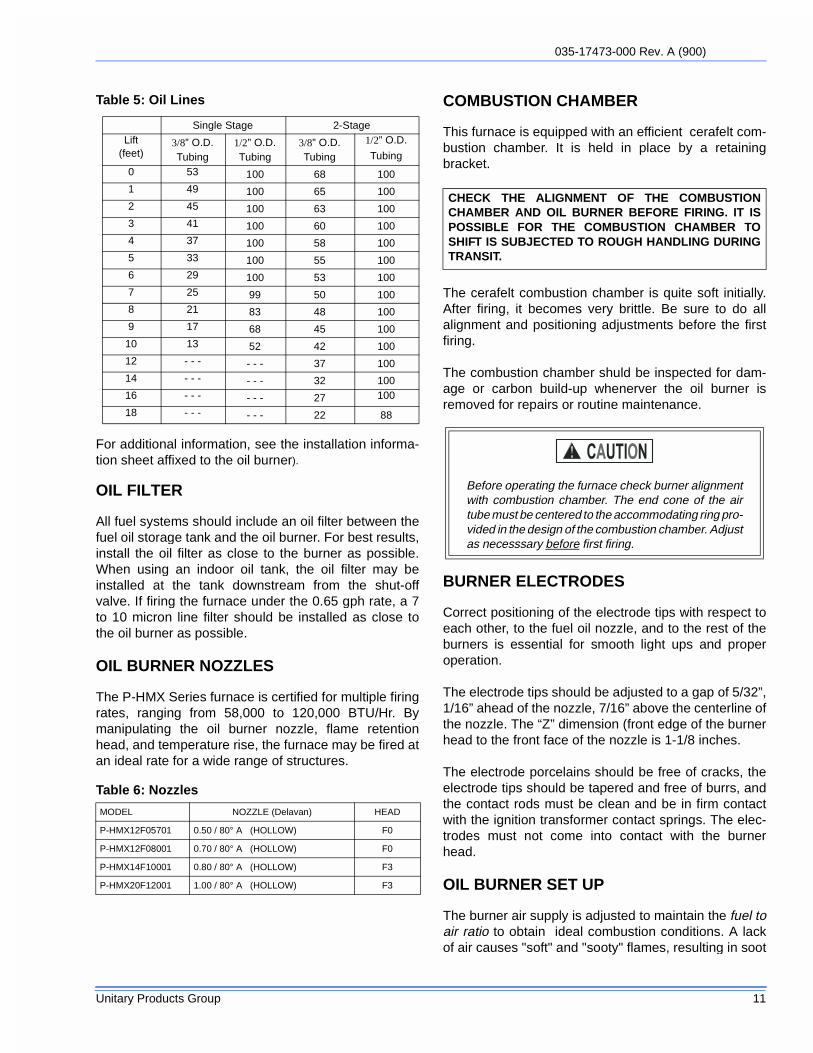
The HMP furnace may be installed with a one pipe sys-tem with gravity feed or lift. The maximum allowable lifton a single line system is 8 feet. Lift should be mea-sured from the bottom (outlet) of the tank, to the inlet ofthe burner. Sizing a single line system is complexbecause of the difficulty estimating the pressure dropthrough each fitting, bend and component in the line. Ingeneral, keep single line systems short as possible. Ifthe furnace is to be installed in a suspended position, atwo pipe system may be the better alternative. 2-stageoil pumps may be used with both single line and twoline systems. 2-stage pumps are available from yourHVAC wholesaler. The following chart shows the allow-able line lengths (horizontal + vertical) for single andtwo stage oil pumps. All distances are in feet.
In retrofit applications, where an existing oil line systemis in place, a vacuum check will help determinewhether a 2-stage oil pump is necessary. The vacuumin a system featuring a single stage oil pump shouldnot exceed 6” Hg. The vacuum in a system featuring a2-stage oil pump should not exceed 15” Hg. (inches ofmercury.
035-17473-000 Rev. A (900)
Unitary Products Group 11
For additional information, see the installation informa-tion sheet affixed to the oil burner).
OIL FILTER
All fuel systems should include an oil filter between thefuel oil storage tank and the oil burner. For best results,install the oil filter as close to the burner as possible.When using an indoor oil tank, the oil filter may beinstalled at the tank downstream from the shut-offvalve. If firing the furnace under the 0.65 gph rate, a 7to 10 micron line filter should be installed as close tothe oil burner as possible.
OIL BURNER NOZZLES
The P-HMX Series furnace is certified for multiple firingrates, ranging from 58,000 to 120,000 BTU/Hr. Bymanipulating the oil burner nozzle, flame retentionhead, and temperature rise, the furnace may be fired atan ideal rate for a wide range of structures.
COMBUSTION CHAMBER
This furnace is equipped with an efficient cerafelt com-bustion chamber. It is held in place by a retainingbracket.
The cerafelt combustion chamber is quite soft initially.After firing, it becomes very brittle. Be sure to do allalignment and positioning adjustments before the firstfiring.
The combustion chamber shuld be inspected for dam-age or carbon build-up whenerver the oil burner isremoved for repairs or routine maintenance.
BURNER ELECTRODES
Correct positioning of the electrode tips with respect toeach other, to the fuel oil nozzle, and to the rest of theburners is essential for smooth light ups and properoperation.
The electrode tips should be adjusted to a gap of 5/32”,1/16” ahead of the nozzle, 7/16” above the centerline ofthe nozzle. The “Z” dimension (front edge of the burnerhead to the front face of the nozzle is 1-1/8 inches.
The electrode porcelains should be free of cracks, theelectrode tips should be tapered and free of burrs, andthe contact rods must be clean and be in firm contactwith the ignition transformer contact springs. The elec-trodes must not come into contact with the burnerhead.
OIL BURNER SET UP
The burner air supply is adjusted to maintain the fuel toair ratio to obtain ideal combustion conditions. A lackof air causes "soft" and "sooty" flames, resulting in soot
Single Stage 2-StageLift
(feet)3/8” O.D.Tubing
1/2” O.D.Tubing
3/8” O.D.Tubing
1/2” O.D.
Tubing
0 53 100 68 1001 49 100 65 1002 45 100 63 1003 41 100 60 1004 37 100 58 1005 33 100 55 1006 29 100 53 1007 25 99 50 1008 21 83 48 1009 17 68 45 100
10 13 52 42 10012 - - - - - - 37 10014 - - - - - - 32 10016 - - - - - - 27 100
18 - - - - - - 22 88
Table 6: Nozzles
MODEL NOZZLE (Delavan) HEAD
P-HMX12F05701 0.50 / 80° A (HOLLOW) F0
P-HMX12F08001 0.70 / 80° A (HOLLOW) F0
P-HMX14F10001 0.80 / 80° A (HOLLOW) F3
P-HMX20F12001 1.00 / 80° A (HOLLOW) F3
Table 5: Oil Lines
CHECK THE ALIGNMENT OF THE COMBUSTIONCHAMBER AND OIL BURNER BEFORE FIRING. IT ISPOSSIBLE FOR THE COMBUSTION CHAMBER TOSHIFT IS SUBJECTED TO ROUGH HANDLING DURINGTRANSIT.
Before operating the furnace check burner alignmentwith combustion chamber. The end cone of the airtube must be centered to the accommodating ring pro-vided in the design of the combustion chamber. Adjustas necesssary before first firing.

035-17473-000 Rev. A (900)
12 Unitary Products Group
build-up throughout the heat exchanger passages.Excess combustion air causes a bright roaring fire andhigh stack temperatures resulting in poor fuel effi-ciency.
PREPARATIONS:
Drill a ¼” test port in the venting, ideally at least 2 diam-eters (12”) away from the furnace breaching, if ventinghorizontally from the furnace, or from the flue pipeelbow if venting vertically before reaching the furnace.(see Figures 1 and 2).
Note A: Locate hole at least 6 inches on the furnaceside of the draft control.
Note B: Ideally, hole should be at least 12 inches frombreeching or elbow.
The test port will allow flue gas samples to be takenand stack temperatures to be measured.
Before starting the burner, check the burner alignmentwith the combustion chamber (fire pot), check that thecorrect nozzle is tightened into place, and that theburner electrodes are properly positioned.
PROCEDURE:
Start the burner and allow it to run at least ten minutes.Set the air shutter to give a good flame visually. The airsupply to the burner is controlled by the air shutter onthe left side of the burner, and the bulk air band. Toadjust, loosen the bolt on the movable shutter. Movethe shutter gradually until a good flame (visually) hasbeen achieved. Re-snug the bolt.
Check the initial draft setting as the furnace warms up.The draft may be measured at the test port. In mostcases, the pressure drop between the test port and theoil burner is negligible. The test port draft reading maybe interpreted as the “over fire draft” reading. The draftshould be set to - 0.02 inches w.c.
Check the oil pump pressure. All P-HMX furnaces aredesigned to be operated at 100 PSIG.
After reaching steady state, take a smoke test. If notindicating a trace, set the combustion air controls toprovide a trace. In most cases, adjustment of the endair shutter will be all that is necessary.
When the trace smoke has been established, measurethe CO2 or O2 in the flue gas. Typically, the CO2 read-ing will be approximately 13% or the O2 readingapproximately 3.3%.
Open the end air shutter (or open the bulk air band ifnecessary) until the CO2 reading drops 1 or 2 percent-
FIGURE 6 : TEST PORT LOCATION FOR SMOKE TEST HORIZONTAL.
FIGURE 7 : TEST PORT LOCATION FOR SMOKE TEST VERTICAL

035-17473-000 Rev. A (900)
Unitary Products Group 13
age points, or, if measuring O2 content, until the O2
reading increases 2 or 3 percentage points.
Take another smoke test; it should now be zero smoke.If the smoke test reads zero, tighten up the end airshutter, and bulk air band.
Re-test the draft, and the CO2 or O2 to be certain thatthe settings have not shifted.
SMOKE TEST NOTE:
If oily or yellow smoke spots are found on the smoketest filter paper, it is usually a sign of unburned fuel.This indicates poor combustion. This type of problemmay be caused by excess draft, excess air, or contami-nated fuel. Do not ignore this indicator.
STACK TEMPERATURE:
Stack temperature will vary depending on fuel input,circulating air blower speed, and burner set up, etc. Ingeneral, stack temperature should range between350°F to 450°F, but could be as high as 550°F, assum-ing that the combustion air is approximately room tem-perature (65°F - 70°F). In general, lower stacktemperature indicates greater efficiency; however,excessively low stack temperature can lead to conden-sation forming in the chimney and / or venting. Sulphurand similar contaminants in the fuel oil will mix withcondensation to form acids. Acids and resultant chemi-cal salts will cause rapid deterioration of the chimneyand venting components, and may attack the furnace.
If the flue gases are below the range, it may be neces-sary to slow down the blower fan. If the flue gases areabove the range, the blower fan may require speedingup. Stack temperature varies directly with the systemtemperature rise. System temperature rise is the differ-ence between the furnace outlet temperature and fur-nace inlet temperature as measured in the vicinity ofthe connection between the plenum take-offs and thetrunk ducts. Typical temperature rise values rangebetween 65°F and 90°F.
If the venting from the furnace to the chimney is long,or exposed to cold ambient temperatures, it is advis-able to insulate the venting with a removable, non-com-bustible, wrap-around type insulation to reduce stacktemperature loss. The venting should be inspectedannually to ensure that it is intact.
CIRCULATING AIR BLOWER
These furnaces are equipped with direct drive blowersystems. Direct drive blower speed adjustments arenot normally required in properly sized extended ple-num duct systems. The motor RPM and air CFM deliv-ery will vary automatically to accommodate conditionswithin the usual range of external static pressures typi-cal of residential duct systems. Under-sized duct sys-tems may require a higher blower speed to obtain areasonable system temperature rise. Some older ductsystems were not designed to provide static pressure.They typically feature special reducing fittings at eachbranch run and lack block ends on the trunk ducts.These systems may require modification to providesome resistance to the airflow to prevent over- ampingof the direct drive blower motor. Selecting a lowerblower speed may correct this problem.
Direct drive blower speeds are adjusted by changingthe "hot" wires to the motor winding connections.Please refer to wiring diagram in Appendix B or the wir-ing diagram label affixed to the furnace. THE NEU-TRAL WIRE (normally the white wire) IS NEVERMOVED TO ADJUST THE BLOWER SPEED.
It is possible and acceptable to use a single blowerspeed for both heating and cooling modes. The sim-plest method to connect the wiring from both modes isto use a "piggy-back connector" accommodating bothwires on a single motor tap. It is also acceptable to
IF THE FURNACE FAILS TO IGNITE, CHECK THEOIL TANK FUEL GAUGE. IF THE FUEL GAUGESHOWS THAT OIL IS PRESENT, PRESS THERESET BUTTON once only. If the burner fails toignite, contact your service contractor.
ALL FURNACE CONTROLS ARE SENSITIVE ANDSHOULD NOT BE SUBJECTED TO TAMPERING. IFPROBLEMS PERSIST, CALL YOUR SERVICE CON-TRACTOR.

035-17473-000 Rev. A (900)
14 Unitary Products Group
connect the selected motor speed with a pig tail joinedto both heating and cooling speed wires with a wire nut.As a safety precaution against accidental disconnec-tion of the wires by vibration, it is advisable to securethe wire nut and wires with a few wraps of electricianstape.
If the joining of the blower speed wiring is done in thefurnace junction box, tape off both ends of the unusedwire.
The circulating fan start-up is delayed 45 seconds inthe heating mode.
The circulating fan start-up is delayed 30 seconds inthe cooling mode. The “fan off” is delayed 30 secondsin the cooling mode.
The “fan off” delay may be field adjusted by manipulat-ing the dip switches. See Figures 6 and 7.
Do not use the blower speed wires as a source ofpower to accessories as electronic air cleaners andhumidifier transformers. The unused motor taps auto-generate sufficiently high voltages to damage acces-sory equipment. Use the terminals provided on theST7997 OEFT.
Additional ST7997A Fan Timer Control information is inAppendix A, Tables, and in Appendix B, Wiring Dia-grams.
MAINTENANCE AND SERVICE
A: Routine Maintenance By Home Owner
Other than remembering to arrange for the annual pro-fessional servicing of the furnace by the service orinstallation contractor, the most important routine ser-
FIGURE 8 : HEATING MODE “BLOWER OFF” TIMINGS, ST9103
DO NOT CONNECT POWER LEADS BETWEENMOTOR SPEEDS. THE NEUTRAL WIRE MUSTALWAYS BE CONNECTED TO THE MOTOR'S DES-IGNATED NEUTRAL TERMINAL.
DISCONNECT THE POWER SUPPLY TO THE FUR-NACE BEFORE OPENING THE BLOWER ACCESSDOOR TO SERVICE THE AIR FILTER, FAN ANDMOTOR. FAILURE TO SHUT OFF POWER COULDALLOW THE BLOWER TO START UNEXPECT-EDLY, CREATING A RISK OF DEATH OR PER-SONAL INJURY.
FIGURE 9 : HEATING MODE “BLOWER OFF” TIM-INGS ST7997
do not start the burner or blower fan unless the bloweraccess door is securely in place.

035-17473-000 Rev. A (900)
Unitary Products Group 15
vice performed by the home owner is to maintain theair filter or filters. A dirty filter can cause the furnace toover-heat, fail to maintain indoor temperature duringcold weather, increase fuel consumption and causecomponent failure.
The furnace filter(s) should be inspected, cleaned orreplaced monthly. The furnace is factory equipped witha semi-permanent type filter. If the filter is damaged,replace with filters of the same size and type.
During the routine service, inspect the general condi-tion of the furnace watching for signs of oil leaks in thevicinity of the oil burner, soot forming on any externalpart of the furnace, soot forming around the joints in thevent pipe, etc. If any of these conditions are present,please advice your service or installation contractor.
B: Annual Service By Contractor
The heat exchanger should be inspected periodicallyand cleaned if necessary. if cleaning is necessary,SHUT OFF POWER TO THE FURNACE and removethe burner. Using a stiff brush with a wire handle, brushoff scale and soot from inside the drum and flue pipe.To clean the radiator, remove the round covers on theinner radiator access pipes located on the front panelbetween the oil burner and the flue pipe.
A wire brush can be used to loosen dirt and debris onthe inside surfaces of the radiator. Clean out all accu-mulated dirt, soot and debris with a wire handled brushand an industrial vacuum cleaner. Replace the clean-out covers.
Most direct drive blower motors are permanently lubri-cated by the motor manufacturer. These motors willhave no oil ports. If the blower motor does contain oilports, under normal operating conditions it will notrequire oiling for the first two years. Oil sparingly (a fewdrops) in each oil port with SAE 20 non-detergent oil.Oiling is most easily done with a "tele-spout" oilier. Thisoilier has a long flexible plastic spout. DO NOT OVER-LUBRICATE. Excess oil causes premature electricmotor failure.
Inspect the blower fan. Clean it if necessary.
Oil Burner Maintenance: Follow the instructions of theoil burner manufacturer. (See oil burner manufacturer'sinstructions supplied with furnace). The oil burner noz-zle should be replaced annually. We recommend thatthe oil filter be changed on an annual basis.
The venting system should be cleaned and inspectedfor signs of deterioration. Replace pitted or perforatedvent pipe and fittings. The barometric damper shouldopen and close freely.
All electrical connections should be checked to ensuretight connections. Safety controls such as the high limitcontrols should be tested for functionality. The fan con-trol functions should be checked to ensure that all fanspeeds are operating properly.
FURNACE INSTALLATION SET UP
The furnace must be set up as the final step in theinstallation.
A. The oil burner must be set up following the pro-cedures outlined in section 17: Oil Burner SetUp.
B. The P-HMX12F057011 and P-HMX12F08001should operate within a temperature rise of60°F to 85°F; the P-HMX14F10001 and P-HMX20F1201 should operate within a temper-ature rise of 60°F to 80°F. To determine thetemperature rise, measure the supply air andreturn air temperatures when the furnace hasreached steady state conditions. This is thepoint at which the supply air temperature stopsincreasing relative to the return air tempera-ture. The furnace may have to run 10 to 15minutes to reach steady state conditions. Themeasurements may be made with duct ther-mometers or thermocouples used in conjunc-tion with multi-meters with temperaturemeasurement capabilities.
The return air should be measured at a point where thethermometer will be well within the air stream near thefurnace return air inlet.. Actual location is not particu-larly critical; however, avoid locations where the tem-perature readings could be affected by humidifierbypass ducts, the inside radius of elbows, etc.
The supply air temperature should be measured at apoint where the thermometer will be well within the airstream near the furnace supply air outlet. Usually, the
The Combustion chamber (firepot) is fragile. use carewhen inspecting and cleaning this area.

035-17473-000 Rev. A (900)
16 Unitary Products Group
side mid-point of the supply air plenum take-off is ideal,providing it is out of the line of sight to the heatexchanger. If the thermometer is within the line of sightof the heat exchanger, the supply air readings may beskewed by radiant heat from the heat exchanger. If theplenum take-off is unsuitable, the supply air tempera-ture may be measured within the first 18 inches of thefirst segment of supply air trunk duct.
If the temperature rise is outside the recommendedrange, it may be adjusted by selecting alternate circula-tion fan motor speeds. If the temperature rise is toohigh, speed the fan up. If the temperature rise is toolow, slow the fan down.
c. Keep in mind that the stack temperature variesdirectly with the temperature rise. The higherthe temperature rise, the higher the stack tem-perature will be, resulting in lower efficiency.The lower the temperature rise, the lower thestack temperature will be, which, in somecases, may allow condensation to form in thechimney and other vent parts.
d. Test the high limit control to ensure that it isoperating correctly. This may be done by tem-porarily removing the circulator fan heatingwire or neutral wire. Turn of electrical power tothe furnace before working with the motorwires. Be sure to protect any removed wiresfrom shorting out on metal furnace parts. If thehigh limit test is successful, shut off the electri-cal power to the furnace, restore the propermotor wiring. Then restore power to the fur-nace.
e. Operate the furnace through a minimum ofthree full heating cycles. During this time,check for fuel oil leaks, gross air leakage fromthe supply air ductwork, unusual noises origi-nating anywhere within the heating systemwhich may cause some concern or annoyanceto the home owner, etc.
f. Be sure that the home owner is familiar withthe furnace. The home owner should be awareof the location of electrical circuit breaker or
fuse, the location of any electrical switchescontrolling the furnace, the location of the oiltank shut-off valve and how to operate thevalve. The home owner should know where theoil tank gauge is located and how to read it.
It would be beneficial to review safety issues with thehome owner, such as the danger of storing combusti-bles too close to the furnace, hanging anything on thefurnace vent pipe, and especially the dangers of indis-criminately pressing the burner reset button.
IMPORTANT: Be sure that the home owner knowswhere the burner reset switch is located, and is awarethat the reset switch is not to be activated more thanonce without a look for the cause of the problem, (lackof fuel, etc.). Be sure that the homeowner knows whento quit trying to start the furnace during these condi-tions and who to call for emergency service.
OPERATING INSTRUCTIONS
Before Lighting
• Open all supply and return air registers and grilles.• Open all valves in oil pipes.• Turn on electric power supply.To Light Unit
• Set the thermostat above room temperature to call for heat. The burner will start. NOTE: If the furnace has been off for an extended period of time, it may be necessary to press the RESET button on the primary combustion control relay, (once only). If pressing the reset button does not start the fur-nace, refer to Appendix C, Troubleshooting.
• After 45 seconds, as the furnace becomes warm, circulation fan will start.
• The furnace will continue to run until the thermostat call for heat is satisfied.
• Set the thermostat below room temperature. The oil burner will stop.
• The air circulation blower will continue to run for 60, 90, 120 or 150 seconds after the oil burner has stopped, depending on the dip switch settings.
035-17473-000 Rev. A (900)
Unitary Products Group 17
To Shut Down Unit
• Set the thermostat to the lowest possible setting.
• Set the manual switch (if installed) in the Electrical Power Supply Line to "OFF".
NOTE: If the furnace is to be shut down for anextended period of time, close the oil supply valve tothe oil burner.
do not attempt to start the burner when excess oil hasaccumulated, when the furnace is full of vapour, orwhen the combustion chamber is very hot. never burngarbage or paper in the furnace, and never leavepaper or rags around the unit.

035-17473-000 Rev. A (900)
18 Unitary Products Group
In the United States, the R. W. Beckett “AF” Burner may be equipped with Beckett’s “Inlet Air Shut-Off”,Beckett Part No. AF/A 5861, to increase efficiency. It reduces the amount of air passing through the oilburner, combustion chamber, breaching, etc. up the chimney between burner cycles.
NOTE: THE USE OF THIS CONTROL CAN OCCASIONALLY CAUSE POST COMBUSTIONNOZZLE DRIP.
Table 7: Becket AF Oil Burner Set-UpBECKETT AF SERIES OIL BURNERS
FURNACEMODEL
OUTPUTBTUH
BURNERMODEL NOZZLE
PUMPPRESSURE
FLOWRATE HEAD
STATICPLATE
P-HMX12F5701 58,000 AF76BO 0.50 / 80° A 100 PSIG 0.50 GPH F0 3-3/8 in.
P-HMX12F08001 79,000 AF76BO 0.70 / 80° A 100 PSIG 0.70 GPH F0 3-3/8 in.
P-HMX14F0001 100,000 AF76XN 0.85 / 80° A 100 PSIG 0.85 GPH F3 3-3/8 in.
P-HMX20F12001 120,000 AF76XN 1.00 / 80° A 100 PSIG 1.00 GPH F3
Table 8: Direct Drive Blower Set-Up
FurnaceModel Blower Motor HP
Blower Set-Up Cooling Capacity
0.20 in. w.c. 0.50 in w.c.Htg. CFM Range.
TonsMotor HP Clg. FM Range
Speed Speedr Tons
P-HMX12F5701G10 DD 1/2
Low Med - Low 629-8913 1/2 900-1200
P-HMX12F08001 Med - High High 857-1214
P-HMX12F5701G12-10 DD 3/4
629-8915 3/4 1200-1900
P-HMX12F08001 857-1214
P-HMX14F0001G10 DD
1/2 1084-16763 1/2 900-1200
P-HMX20F12001 1301-2011
P-HMX14F0001 G12-10 DD 3/41084-1676
5 3/4 1200-2000P-HMX20F12001 1301-2011
035-17473-000 Rev. A (900)
Unitary Products Group 19
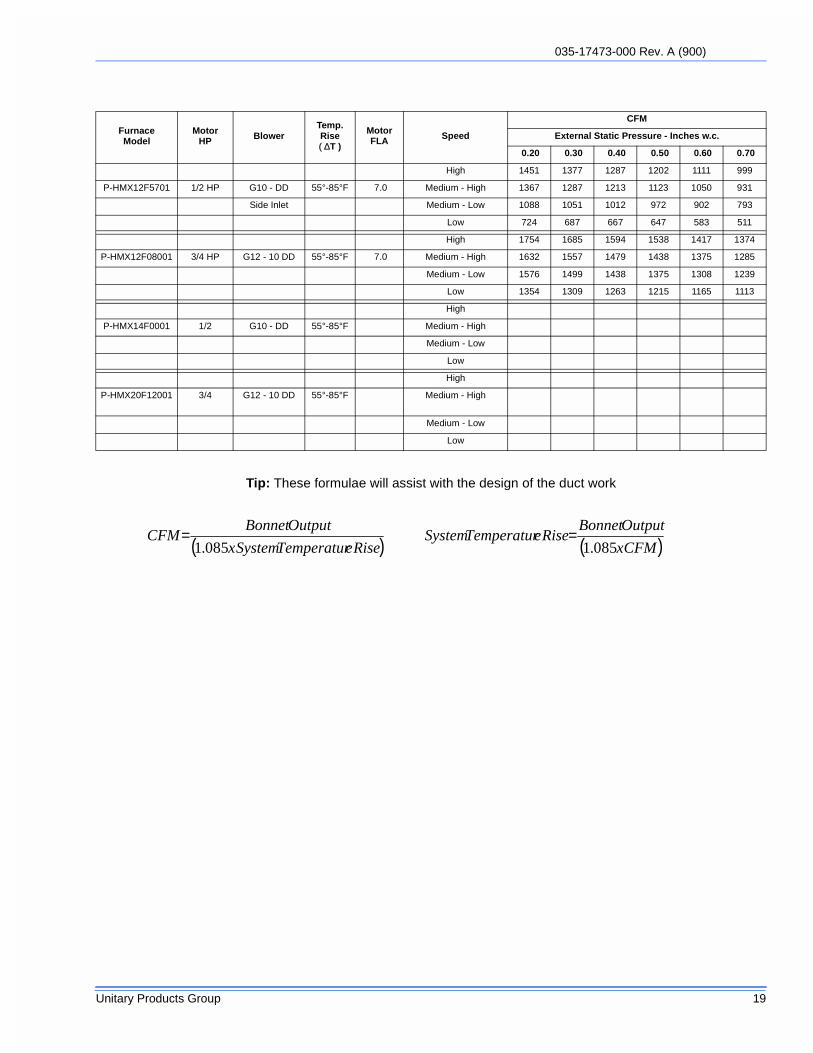
Tip: These formulae will assist with the design of the duct work
FurnaceModel
MotorHP Blower
Temp.Rise( ∆T )
MotorFLA Speed
CFM
External Static Pressure - Inches w.c.
0.20 0.30 0.40 0.50 0.60 0.70
High 1451 1377 1287 1202 1111 999
P-HMX12F5701 1/2 HP G10 - DD 55°-85°F 7.0 Medium - High 1367 1287 1213 1123 1050 931
Side Inlet Medium - Low 1088 1051 1012 972 902 793
Low 724 687 667 647 583 511
High 1754 1685 1594 1538 1417 1374
P-HMX12F08001 3/4 HP G12 - 10 DD 55°-85°F 7.0 Medium - High 1632 1557 1479 1438 1375 1285
Medium - Low 1576 1499 1438 1375 1308 1239
Low 1354 1309 1263 1215 1165 1113
High
P-HMX14F0001 1/2 G10 - DD 55°-85°F Medium - High
Medium - Low
Low
High
P-HMX20F12001 3/4 G12 - 10 DD 55°-85°F Medium - High
Medium - Low
Low
( ) ( )CFMx
OutputBonnetRiseeTemperaturSystem
RiseeTemperaturSystemx
OutputBonnetCFM
085.1085.1==
035-17473-000 Rev. A (900)
20 Unitary Products Group
.
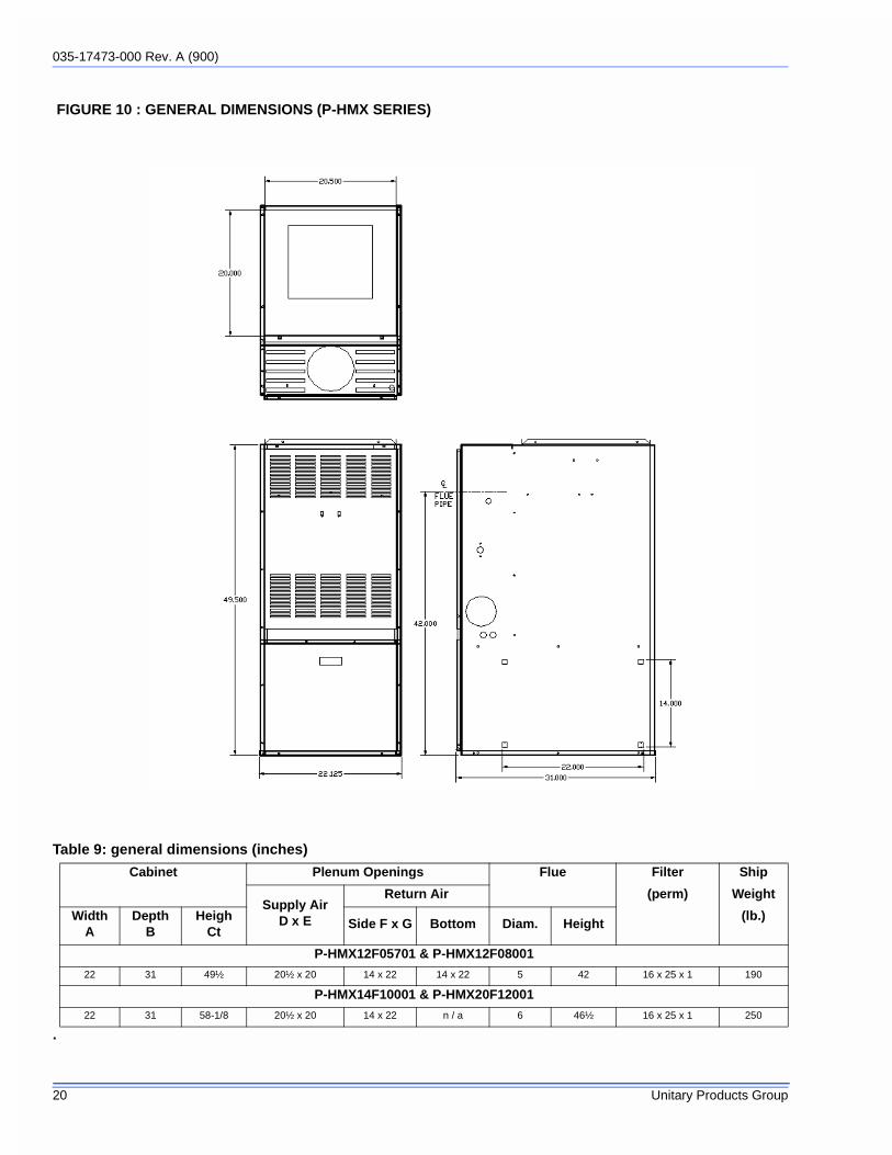
FIGURE 10 : GENERAL DIMENSIONS (P-HMX SERIES)
Table 9: general dimensions (inches)
Cabinet Plenum Openings Flue Filter Ship
Supply AirD x E
Return Air (perm) Weight
WidthA
DepthB
HeighCt
Side F x G Bottom Diam. Height(lb.)
P-HMX12F05701 & P-HMX12F08001
22 31 49½ 20½ x 20 14 x 22 14 x 22 5 42 16 x 25 x 1 190
P-HMX14F10001 & P-HMX20F12001
22 31 58-1/8 20½ x 20 14 x 22 n / a 6 46½ 16 x 25 x 1 250

035-17473-000 Rev. A (900)
Unitary Products Group 21
FIGURE 11 : WIRING DIAGRAM - OIL FURNACE WITH ST9103A EFT & R7184A CONTROL
FIGURE 12 : OIL FURNACE WITH ST7997 OEFT & R7997 CONTROL
035-17473-000 Rev. A (900)
22 Unitary Products Group
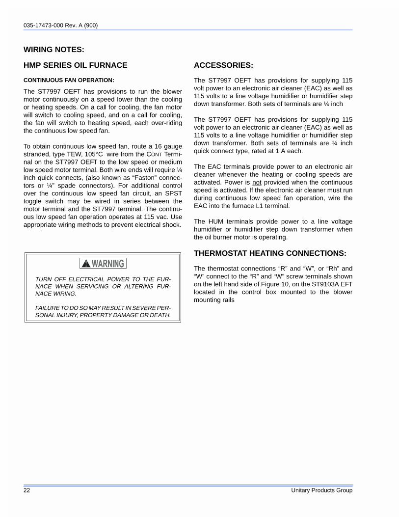
WIRING NOTES:
HMP SERIES OIL FURNACE
CONTINUOUS FAN OPERATION:
The ST7997 OEFT has provisions to run the blowermotor continuously on a speed lower than the coolingor heating speeds. On a call for cooling, the fan motorwill switch to cooling speed, and on a call for cooling,the fan will switch to heating speed, each over-ridingthe continuous low speed fan.
To obtain continuous low speed fan, route a 16 gaugestranded, type TEW, 105°C wire from the CONT Termi-nal on the ST7997 OEFT to the low speed or mediumlow speed motor terminal. Both wire ends will require ¼inch quick connects, (also known as “Faston” connec-tors or ¼” spade connectors). For additional controlover the continuous low speed fan circuit, an SPSTtoggle switch may be wired in series between themotor terminal and the ST7997 terminal. The continu-ous low speed fan operation operates at 115 vac. Useappropriate wiring methods to prevent electrical shock.
ACCESSORIES:
The ST7997 OEFT has provisions for supplying 115volt power to an electronic air cleaner (EAC) as well as115 volts to a line voltage humidifier or humidifier stepdown transformer. Both sets of terminals are ¼ inch
The ST7997 OEFT has provisions for supplying 115volt power to an electronic air cleaner (EAC) as well as115 volts to a line voltage humidifier or humidifier stepdown transformer. Both sets of terminals are ¼ inchquick connect type, rated at 1 A each.
The EAC terminals provide power to an electronic aircleaner whenever the heating or cooling speeds areactivated. Power is not provided when the continuousspeed is activated. If the electronic air cleaner must runduring continuous low speed fan operation, wire theEAC into the furnace L1 terminal.
The HUM terminals provide power to a line voltagehumidifier or humidifier step down transformer whenthe oil burner motor is operating.
THERMOSTAT HEATING CONNECTIONS:
The thermostat connections “R” and “W”, or “Rh” and“W” connect to the “R” and “W” screw terminals shownon the left hand side of Figure 10, on the ST9103A EFTlocated in the control box mounted to the blowermounting rails
TURN OFF ELECTRICAL POWER TO THE FUR-NACE WHEN SERVICING OR ALTERING FUR-NACE WIRING.
FAILURE TO DO SO MAY RESULT IN SEVERE PER-SONAL INJURY, PROPERTY DAMAGE OR DEATH.

035-17473-000 Rev. A (900)
Unitary Products Group 23
NOTE: All thermostat wires for both heating and cool-ing connect to the furnace at this point. A factoryinstalled wiring harness connects the heating controlfunctions to the R7184A oil primary control.
If equipped with the ST7997 OEFT, the thermostat con-nections “R” and “W”, or “Rh” and “W” connect to theburner primary terminal “T” and “T”. If the “T - T” con-nections are not located on the rear of the primary con-trol, they will be on the side of the control between theprimary control and the fan timer Figure 15 onpage 23,.
Figure 8, on page 14, shows the detail of the timed“Blower Off” dip switch settings. Figure 10 shows thedip switch location along the bottom edge of the controlboard, just above the “Honeywell” label.
Figure 9 on the previous page shows details of theR7997 / ST7997 control system.
NOTE: The Honeywell R8184G may be used in placeof the R7184A. The R8184G is an intermittent ignitioncontrol whereas the R7184A is an interrupted ignitioncontrol. the R8184G continues to provide a spark dur-ing the entire burner cycle whereas the R7184A dis-continues the spark after the flame has been proved.The R8184G does not have the diagnostic led featuresfound on the R7184A oil primary controls.
FIGURE 13 : R7997 / ST7997 COMPONENTS
FIGURE 14 : THERMOSTAT CONNECTIONS ST9103A
FIGURE 15 : THERMOSTAT HEATING CONNEC-TIONS ST7997

035-17473-000 Rev. A (900)
24 Unitary Products Group
R7184 DETAILED SEQUENCE OF OPERATION
A. Safety check is made for flame (4 second delay).
1. When flame is not present, the R7184 will apply powerto the burner motor and ignition transformer.
2. When flame is present, the control remains in the idlestate.
B . Control enters the trial for ignition state.
C. Control monitors the burner flame.
1. When flame is present, the control enters ignition carry-over state. (Continues to spark for 10-30 seconds).
a. Provides continuous spark after flame is sensed toassure that burner remains lit.
b. Turns on LED diagnostic light.
c. Starts carryover timer.
i Flame and call for heat are monitored.
• If flame is lost and lockout timer has notexpired, R7184 will return to trial for ignition state.
• If flame is lost and lockout timer has expired,R7997 will enter the recycle state.
♦ Recycle timer starts.
♦ Burner motor and igniter are turned off.
♦ LED diagnostic light flashes slow.
♦ Returns to idle state when recycle timer expires(60 seconds).
d. .Carryover timer expires.
i. Enters run state.
• Igniter turns off.Combustion continues unti thermostat is satisfied orR7184 detects a loss of flame and enters into RecycleMode.
Thermostat is satisfied - call for heat is terminated:
• R7184 shuts off burner motor.
• LED diagnostic light is off.
• R7184 returns to idle state.
035-17473-000 Rev. A (900)
Unitary Products Group 25
R7997 DETAILED SEQUENCE OF OPERATION
Thermostat calls for heat:
A. Safety check is made for flame (4 second delay).
1. When flame is not present, the R7997 will apply powerto the burner motor.
2. When flame is present, the control remains in the idlestate.
B . Control enters the trial for ignition state.
C. Control monitors the burner flame.
1. When flame is present, the control enters ignition carry-over state.
a. Provides continuous spark after flame is sensed toassure that burner remains lit.
b. Turns on LED diagnostic light.
c. Starts carryover timer.
i Flame and call for heat are monitored.
• If flame is lost and lockout timer has notexpired, R7997 will return to trial for ignition state.
• If flame is lost and lockout timer has expired,R7997 will enter the recycle state.
♦ Recycle timer starts.
♦ Burner motor and igniter are turned off.
♦ LED diagnostic light flashes slow.
♦ Returns to idle state when recycle timer expires(60 seconds).
d. .Carryover timer expires.
i. Enters run state.
• Igniter turns off.
Thermostat is satisfied - call for heat is terminated:
• R7997 shuts off burner motor.
• LED diagnostic light is off.
• R7997 returns to idle state.

035-17473-000 Rev. A (900)
26 Unitary Products Group
FIGURE 16 :
IDLE STATE
THERMOSTAT CALLS FOR HEAT
SAFETY CHECK FOR FLAME
BURNER MOTOR STARTS
TRIAL FOR IGNITION
FLAMENO FLAME
BURNER FLAME MONITORED
CARRYOVER STATE
• Provides Continuous Spark• LED Diagnostic Light On• Start Carryover Timer
NO FLAMEFLAME
FLAME
FLAME
FLAME LOST
FLAME LOST
CARRYOVER TIMER EXPIRES
RUN STATE
• Ignitor Turns Off
THERMOSTAT SATISFIED
R7997 SHUTS OFF:
• Burner Motor• LED Diagnostic Light
RETURNS TO IDLE STATE
REMAINS IN IDLE STATE
LOCKOUT STATE
R7997:
• Shuts off burner motor• Shuts off ignitor• Fast Flashes LED
diagnostic light.
TO EXIT LOCKOUTPRESS RESET
R7997:
• Shuts off burner motor• Shuts off ignitor• Slow Flashes LED
diagnostic light.
RECYCLE TIMER STARTS
RECYCLE TIMER EXPIRES(60 SECONDS)
R7997SEQUENCE
ofOPERATION

035-17473-000 Rev. A (900)
Unitary Products Group 27
Table 10: ST9301A Detailed Sequence of Operation
Mode Action System Response
HEAT
Thermostat calls for heat. ("W" termi-nal is energized).
a. ST9103A closes oil primary control T-T connections.b. Ignition system and R7184A and R8184G oill primary control start the
furnace. Oil flows as long as the oil primary control senses flame.c. Burner motor is energized and heat “fan on” delay timing begins. When
timing is complete (30 seconds), the circulator fan is energized at heatspeed.
Thermostat ends call for heat. ("W" terminal is de-energized).
a. R7184A or R8184G oil primary control lis de-energized, terminating theburner cycle.
b. Heat “fan off” delay timing begins. Length of delay depends on ST9103Adip switch settings. When timing is complete, the circulator fan is de-energized.
c. ST9103A returns to standby mode. (Oil primary control and circulator fanare off, unless continuous fan operation is selected at the thermostat).
Burner fails to light.
a. Oil primarly control locks out within lockout timing (30 seconds).b. Burner motor is de-energized. (Even though thermostat is still calling for
heat).c. If circulator fan has started it continues through the selected heat (fan
off” delay period.
Established flame fails.
a. Burner motor is de-energized and oil primary control goes into recyclemode.
b. If the selected heat “fan off” delay timing is longer than the recycle delaytiming, the circulator fan continues to run through the next trial for igni-tion.
COOL
Thermostat begins call for cool. (G and Y terminals are energized).
a. Cooling contactor is energized immediately.b. Circulator fan is energized at cool speed.
Thermostat ends call for cool. (G and Y terminals are de-energized).
a. Cooling contactor is de-energized immediately.b. Circulator fan turns off immediately.
FAN
Thermostat begins call for fan. (G terminal is energized).
a. Circulator fan is energized immediately at cooling speed.
Thermostat ends call for fan. (Y ter-minal is de-energized).
a. Circulator fan is de-energized immediately.
LIMIT Limit switch string opens.
a. Oil primary control shuts off burner.b. Circulator fan is energized immediately at heat speed.c. ST9103A opens oil primary control T-T connections.d. Circulating fan runs as long as limit string stays open.
If there is a call for cooling or a fan, the circulating fan switches from heating tocooling speed.
FAN Continuous circulating fan is con-nected.
a. Circulating fan is energized when there is no call for heat, cool, or fan.b. If fan operation is required by a call for heat, cool, or fan, the ST9103A
switches off the continuous fan speed tap before energizing the other fanspeed.
EAC Electronic Air Cleaner is connected• Electronic air cleaner (EAC) connections are energized when the heat or cool
speed of the circulator fan is energized. EAC connections are not energized when the optionional continuous fan termnal is energized.
HUM Humidity control is connected. a. Humidifier connections are energized when the oil burner motor is ener-gized.

035-17473-000 Rev. A (900)
28 Unitary Products Group
Table 11: ST7997 Detailed Sequence of OperationMode Action System Response
HEAT
Thermostat calls for heat. ("W" terminal is energized).
a. Thermostat calls for heat (closes R7997B oil primary control T1 - T2 con-nections).
b. Ignition system and oil primary control start the furnace. Oil flows as long asthe R7997B senses flame.
c. Burner motor is energized, LED diagnostic light turns on, and heat "fan on"delay timing begins. When timing is complete (30 seconds), the circulatorfan is energized at heat speed.
Thermostat ends call for heat. ("W" ter-minal is de-energized).
a. R7997B oil primary control is de-energized, terminating the burner cycle.The LED diagnostic light turns off.
b. Heat "fan off" delay timing begins. Length of delay depends on ST7997 dipswitch settings. When timing is complete, the circulator fan is de-energized.
c. ST7997 returns to standby mode, (R7997B oil primary control and circula-tor fan are off, unless continuous fan operation is selected at the thermo-stat).
Burner fails to light.a. R7997B oil primary control locks out within lockout timing, (30 seconds).
b. Burner motor is de-energized and LED diagnostic light turns off (eventhough thermostat is still calling for heat).
c. If circulator fan has started, it continues through the selected heat “fan off”delay period.
Established flame fails.a. Burner motor is de-energized and LED diagnostic light turns off, and
R7997B oil primary control goes into recycle mode.
b. If the selected heat “fan off” delay timing is longer than the recycle delaytiming, the circulator fan continues to run through the next trial for ignition.
COOL
Thermostat begins call for cool. (G and Y terminals are energized).
a. Cooling contactor is energized and LED diagnostic light turns on immedi-ately.
b. Circulator fan is energized at cool speed when cool “fan on” delay time (30seconds) is complete.
Thermostat ends call for cool. (G and Y terminals are de-energized).
a. Cooling contactor is de-energized and LED diagnostic light turns off imme-diately.
b. Circulator fan turns off when cool “fan off” delay time (30 seconds) is com-plete.
FAN
Thermostat begins call for fan. (G ter-minal is energized).
a. Circulator fan is energized immediately at heat speed and LED diagnosticlight turns on immediately.
Thermostat ends call for fan. (G termi-nal is de-energized).
a. Circulator fan is de-energized and LED diagnostic light turns off immedi-ately.
LIMIT Limit switch string opens.
a. LED diagnostic light flashes at 2 Hz (¼ second on/off).
b. R7997B oil primary control shuts off burner.
c. Circulator fan is energized immediately at heat speed.
LIMIT
Limit switch string closes (with existing call for heat).
a. R7997B oil primary control is energized, initiating burner light-off, and LEDdiagnostic light changes to continuously on.
b. Circulator fan continues to operate at heat speed.
Limit switch string closes (without existing call for heat).
a. LED diagnostic light turns off.
b. Circulator fan turns off when heat “fan off” delay time is complete.
c. Normal operation resumes; ST7997 control is in standby mode awaitingnext thermostat command.
035-17473-000 Rev. A (900)
Unitary Products Group 29
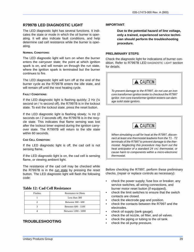
R7997B LED DIAGNOSTIC LIGHTThe LED diagnostic light has several functions. It indi-cates the state or mode in which the oil burner is oper-ating. It will also indicate fault conditions, and helpdetermine cad cell resistance while the burner is oper-ating.
NORMAL CONDITIONS:
The LED diagnostic light will turn on when the burnerenters the carryover state; the point at which ignitionspark is on, and will remain on through the run state,where the ignition spark is terminated but the burnercontinues to fire.
The LED diagnostic light will turn off at the end of theburner cycle as the R7997B enters the idle state, andwill remain off until the next heating cycle.
FAULT CONDITIONS:
If the LED diagnostic light is flashing quickly; 2 Hz (¼second on / ¼ second off), the R7997B is in the lockoutstate. To exit the lockout state, press the reset button.
If the LED diagnostic light is flashing slowly; ¼ Hz (2seconds on / 2 seconds off), the R7997B is in the recy-cle state. This indicates that flame sensing was lostafter the lockout timer expired during the ignition carry-over state. The R7997B will return to the idle statewithin 60 seconds.
CAD CELL CONDITION:
If the LED diagnostic light is off, the cad cell is notsensing flame.
If the LED diagnostic light is on, the cad cell is sensingflame, or viewing ambient light.
The resistance of the cad cell may be checked whilethe R7997B is in the run state by pressing the resetbutton. The LED diagnostic light will flash the followingcode:
TROUBLESHOOTING
IMPORTANT:
Due to the potential hazard of line voltage, only a trained, experienced service techni-cian should perform the troubleshooting procedure.
PRELIMINARY STEPS:
Check the diagnostic light for indications of burner con-dition. Refer to R7997B LED DIAGNOSTIC LIGHT sectionfor details.
Before checking the R7997, perform these preliminarychecks, (repair or replace controls as necessary):
• check the power supply; fuse box or breaker, any service switches, all wiring connections, and burner motor reset button (if equipped).
• check the limit switches to ensure that the switch contacts are closed.
• check the electrode gap and position.• check the contacts between the R7997 and the
electrodes.• check oil supply (tank gauge).• check the oil nozzle, oil filter, and oil valves.• check the piping or tubing to the oil tank.• check the oil pump pressure.
Table 12: Cad Cell ResistanceFlashes Resistance in Ohms
1 Less than 300
2 Between 300 - 600
3 Between 600 - 1100
4 Between 1200 - 5000
To prevent damage to the R7997, do not use an ironcore transformer ignition tester to checkout the R7997ignitor. Iron core transformer ignition testers can dam-age solid state ignitors.
When simulating a call for heat at the R7997, discon-nect at least one thermostat leadwire from the T1 - T2terminals of the R7997 to prevent damage to the ther-mostat. Neglecting this procedure may burn out theheat anticipator of a standard 24 VAC thermostat, orcause harm to components within a micro-electronicthermostat.

035-17473-000 Rev. A (900)
30 Unitary Products Group
Check Oil Primary Control and Ignitor
If the trouble does not appear to be in the burner orignition hardware, check the oil primary control and theignitor by using the following equipment:
• screwdriver.• voltmeter (0 - 150 VAC)• insulated jumper wires with both ends stripped.
Preliminary Checks:
1. Make sure that limit switches are closed and thatcontacts are clean.
1. Check for line voltage power on the oil primarycontrol black and white leadwires.
1. Refer to Table C-3 for further troubleshooting infor-mation.
Electrical Shock Hazard.
Troubleshooting is done with the system powered. Becareful to observe all necessary precautions.to pre-vent electrical shock or equipment damage.

035-17473-000 Rev. A (900)
Unitary Products Group 31
Table 13: R7184A TROUBLESHOOTINGCondition: Burner motor does not start when there is a call for heat.
Procedure Status Corrective Action
1. Check that limit switches areclosed and contacts areclean. This includes theburner motor reset button.
N/A N/A
2. Check for line voltage powerat the oil primary control. Volt-age should be 120 Vacbetween the black and whiteleadwires on the oil primarycontrol.
N/A N/A
3. Check indicator light withburner off, no call for heat (noflame).
Indicator light is on. Cad cell is defective, sees external light, or connections have shorted. Go to step 4.
Indicator light is off. Go to step 5.
4. Shield cad cell from externallight.
Indicator light turns off. Eliminate external light ource or permanently shield cad cell.
Indicator light stays on. • Replace cad cell with new cad cell and recheck.• If indicator light does not turn off, remove yellow
leadwires from R7184A and recheck.•If indicator light is still on, replace the R7184A control.•If indicator light turns off, replace cad cell bracket assembly.
5. Jumper thermostat (T-T) ter-minals on R7184A
Burner starts. Trouble is in thermostat circuit. Check thermostat wiringconnections.If connections re clean and tight, check thermostat wiresfor continuity.
Burner does not start. • Disconnect line voltage power and open line switch.• Check all wiring connections.• Tighten any loose connections and recheck.
If burner still doesn’t start, check the oil burner motor. Itmay be sized or burned out.

035-17473-000 Rev. A (900)
32 Unitary Products Group
R7184A Troubleshooting (continued from previous page)
CONDITION: Burner starts then locks out on safety with indictor light flashing at 1 Hz rate (1/2 secondon, 1/ 2 second off)
Procedure Status Corrective Action
1. Check that the limit switches are closed and contacts are clean.
-- --
2. Check for line voltage power at the oil primary control. Voltage should be 120 vac (nominal).
-- --
3. Check indicator light with burner off, no call for heat (no flame).
Indicator light is on.
Cad cell or controller is defective, sees external light, or connections are shorted. Go to step 4.
Indicator light is off.
Go to step 5.
4. Shield cad cell from external light. indicator light turns off.
Eliminate external light source or permanently shield cad cell.
Indicator light stays on.
Replace cad cell with new cad cell and recheck.
5. Jumper thermostat (T-T) terminals on R7184AImportant:First remove one thermostat leadwire.
Burner starts Trouble in thermostat or limit circuit. Check thermo-stat or limit wiring connections.
Burner does not start
Disconnect the line voltage power and open line switch.Check all wiring connections.Tighten any loose connections and recheck.If burner does not start, replace R7184A. .

035-17473-000 Rev. A (900)
Unitary Products Group 33
R7184A Troubleshooting (continued from previous page)
CONDITION: Burner starts then locks out on safety with indictor light flashing at 1 hz rate (1/2 second on, 1/2 second off)
Procedure Status Corrective Action
6. Reset oil primary control by pushing in andreleasing red reset button.
Indicator light stops flashing.
Go to step 7.
Indicator light continues to flash at 1 Hz rate.
Verify that the control is not in restricted mode. (See notes at end of this table.) If not in restricted mode, replace R7184A.
7. Listen for spark after burner turns on (after 2second delay).
Ignition is off Spark ignitor could be defective. Check for line volt-age at ignitor terminals. If line voltage is present, replace R7484.
Ignition is on. Go to step 8.
Ignition is on but no oil is being sprayed into the combustion chamber.
Check oil supply, and oil ine valve. Check for filter blockage or seized oil pump.
8. Check indicator light after flame is established,but before oil primary control locks out.
Indicator light is on until the con-trol locks out and starts flashing during lockout.
Replace R184A.
Indicator light stays off.
Go to step 9.
9. Check for cad cell sighting for view of flame:• Disconnect line voltage power nd open line
switch.• Unplug cad cell and clean cad cell face with
soft cloth. Check sighting for clear view of flame. Replace cad cell in socket.
• Reconnect line voltage power and close line switch.
• Start burner.
Burner locks out. Go to step 10.
Burner keeps running
System is OK
10. Check cad cell.• Disconnect line voltage power and open line
switch.• Remove existing cad cell and replace within
new cad cell.• Disconnect all wires from thermostat terminals
to ensure that there is no call for heat.• Reconnect line voltage power and close line
switch.• Expose new cad cell to bright light such as a
flashlight.
Indicator light is on.
Remount control onto burner housing. Go to step 6.
Indicator light is off.
Go to step 11.

035-17473-000 Rev. A (900)
34 Unitary Products Group
R7184A Troubleshooting (continued from previous page)
Procedure Status Corrective Action
11. Check cad cell bracket assembly.
• Disconnect line voltage power and open line switch.• Remove cad cell wires from quick connect connectors on the
R7184 and leave control leadwires open.• Apply power to device.• Place jumper across cad cell terminals after burner motor
turns on.
Indicator light is on. Replace cad cell bracketassembly.
Indictor light is off. Replace R7184A.
NOTE: Restricted Mode - (Limited Reset): In order to limit the accumulation of unburned oil in the combustionchamber, the control can be reset only 3 times, after which, the control locks out. The reset count returnsto zero each time a call for heat is successfully completed.
To reset from Restricted Mode: Press and hold the reset button for 30 seconds. When the LED flashestwice, the device has reset.
NOTE: Disable function: Pressing and holding the reset button will disable all functions until the button isreleased. The R7184 will restart at the beginning of the normal heat cycle on Safety Check.

035-17473-000 Rev. A (900)
Unitary Products Group 35
Table 14: R7997B TROUBLESHOOTING
Condition: Burner motor does not start when there is a call for heat.
Procedure Status Corrective Action
1. Check that limit switches are closed and contacts areclean. This includes the burner motor reset button.
N/A N/A
2. Check for line voltage power at the oil primary control.Voltage should be 120 VAC between the black andwhite leadwires on the oil primary control.
N/A N/A
3. Check indicator light with burner off, no call for heat(no flame).
Indicator light is on. Cad cell is defective, sees exter-nal light, or connections have shorted. Go to step 4.
Indicator light is off. Go to step 5.
4. Shield cad cell from external light. Indicator light turns off. Eliminate external light source orpermanently shield cad cell.
Indicator light stays on.
5. Jumper thermostat (T1-T2) terminals at R7997BImportantFirst remove one thermostat leadwire.
Burner starts.
• Replace cad cell with new cad cell and recheck.
• If indicator light does not turn off, cut yellow leadwires near cad cell bracket and recheck.
• If indicator light is still on, replace the control portion of R7997B with the same Q7997.
• If the indicator light turns off, replace cad cell bracket assembly.
Burner does not start.
• Disconnect line voltage power and open line switch.
• Check all wiring connecitons.• Tighten any loose connec-
tions and recheck.
If burner stilll doesn’t start, checkthe oil burner motor. It may beseized or burned out.
Condition: Burner starts then locks out on safety with indictor light flashing at 2 Hz (fast flash)
6. Reset oil primary control by pushing in and releasingred reset button.
Indicator light stops flash-ing.
Go to step 7.
Indicator light continues toflash at 2 Hz.
Replace ignition portion of theR7997B with the appropriateQ7997.

035-17473-000 Rev. A (900)
36 Unitary Products Group
7. Listen for spark after burner turns on (has 2 seconddelay).
Ignition is off. Replace ignition portion of theR7997B with the appropriateS7997.
Ignition is on. Go to step 8.
Ignition is on but no oil isbeing sprayed nto the com-bustion chamber.
Check oil tank valve, pump and oilsupply.
8. Check indicator light after flame is established, butbefore oil primary control locks out.
Indicator light is on until thecontrol locks out and startsflashing during lockout.
Replace control portion of R7997Bwith the appropriate Q7997.
Indicator light stays on. Indicator light does not turn on. Goto step 9.
9. Check cad cell sighting for view of flame.
• Disconnect line voltage power and open line switch.• Unplug cad cell and clean cad cell face with soft cloth.
Check sighting for clear view of flame. Replace cad cell in socket.
• Reconnect line voltage power and close line switch. Start burner.
Burner locks out. Go to step 10.
Burner keeps running.Check all wiring connections, cadcell is OK.
10. Check cad cell.
• Disconnect line voltage power and open line switch.• Remove existing cad cell and replace with new cad
cell.• Disconnect all wires from thermostat terminals to
ensure that there is no call for heat.• Reconnect line voltage power and close line switch.• Expose new cad cell to bright light such as a flashlight.
Indicator light is on. Remount control onto burnerhousing. Go to step 6.
Indicator light is off. Go to step 11.
11. Check cad cell bracket assembly.
• Disconnect line voltage power and open line switch.• Cut yellow leadwires near cad cell bracket and leave
the control leadwires open.• Apply power to device.
Indicator light is off. Replace cad cell bracket assem-bly.
Indicator light is on. Replace the control portion ofR7997B with the appropriateQ7997.
Table 14: R7997B TROUBLESHOOTING

035-17473-000 Rev. A (900)
Unitary Products Group 37
Table 15: System & General Troubleshooting
Problem Possible Cause Remedy
Furnace will not start
Thermostat not calling for heat.
Check thermostat and adjust. Also, check thermostat for accuracy; if it is a mercury switch type, it might be off level.
No power to furnace.
Check furnace switch, main electrical panel furnace fuse or circuit breaker. also look for any other hand operated switch, such an old, poorly located furnace switch which was not removed during furnace replacement.
Thermostat faulty.
Remove thermostat wires from oil primary control terminals T1-T2. Place a jumper across T1-T2. If furnace starts, replace thermostat, thermostat sub-base (if equipped), or both. R7184 = T - T, R7997 = T1 - T2.
Oil primary control faulty.
Check reset button on oil primary control. Remove thermostat wires from oil primary control terminals T1-T2. Check for 24v across T-T. If no voltage is present, check for 115v to oil primary control. If 115v is present, go to Table C-3.
Photo Cell wiring shorted or room light leaking into photo cell compartment.
Check photo cell (cad cell) wiring for short circuits. Also, check for room light leaking into cad cell compartment. Repair light leak if necessary. See Table C-3.
Open safety switch.Check for open limit or auxiliary limit. also, check internal wiring connections; loose connectors, etc.

035-17473-000 Rev. A (900)
38 Unitary Products Group
Furnace will not start without first pushing oil primary control reset button.
(Happens on frequent basis)
No fuel oil.Check fuel oil supply. Check that all hand operated fuel oil valves are in the open position. Fill oil storage tank if necessary.
Clogged nozzle.Replace nozzle with high quality replace-ment. Use rating plate or Tables in Appen-dix A as a guide.
Clogged oil filter.Replace oil tank filter or in-line filter if used.
Low oil pump pressure.
Connect pressure gauge to oil pump. Adjust pump pressure, or replace oil pump if necessary. Ensure that erratic pressure readings are not caused by defective fuel oil line.
Air getting into fuel oil lines, or fuel oil line dirty, clogged, or in some manner defective.
Check fuel oil lines. Replace any com-pression fittings found with high quality flared fittings. Check for any signs of oil leaks. Any oil leak is a potentio
Defective burner motor. Check burner motor. If burner motor is cutting out on over-load, determine why. Replace if necessary.
Furnace starts, but cuts out requiring manually resetting the oil protector reset button.
Photo Cell (Cad Cell) defective.
If cad cell is dirty, clean it. (Determine why cad cell is getting dirty). If cad cell is poorly aimed, realign it. NOTE: the photo cell shuld have a resis-tance of 100KΩ in absence of light; a maximum of 1500Ω in the presence of light. Ensure that room light is not leaking the cad cell compartment. (See diagnostic light section).
Table 15: System & General Troubleshooting

035-17473-000 Rev. A (900)
Unitary Products Group 39
Furnace starts but cuts out requiring manual resetting the oil protector reset button.
No fuel oilCheck fuel oil supply. Check that all hand operated fuel oil valves are in the open position. Fill oil storage tank if necessary.
Clogged nozzle.Replace nozzle with high quality replace-ment. Use rating plate or Tables in Appen-dix A as a guide.
Clogged oil filter.Replace oil tank filter or in-line filter if used.
Low oil pump pressure.
Connect pressure gauge to oil pump. Adjust pump pressure, or replace oil pump if necessary. Ensure that erratic pressure readings are not caused by defective fuel oil line.
Air getting into fuel oil lines, or fuel oil line dirty, clogged, or in some manner defective.
Check oil fuel lines. Replace any com-pression fittings found with high quality flared fittings. Check for any signs of oil leaks. Any oil leak is a potential source of air or contaminants.
Defective burner motor.Check burner motor. If burner motor is cut-ting out on over-load, determine why. Replace if necessary.
Water or contaminants in oil.
Drain fuel oil storage tank, replace fuel oil. (Consult with fuel oil supplier).
Frozen oil line.Gently warm oil line. Insulate oil line. (Out-door piping size may require increase diameter).
Oil burner sputtering at nozzle.
Electrodes out of adjustment or defective.
Check electrode settings. Check elec-trodes for dirt buildup or cracks in porce-lain.
Poor transformer high voltage connections or defective transformer.
Check contacts between ignition trans-former and electrodes or R7997 ignitor and electrodes. If OK, replace ignition transformer or S7997 portion of R7997.
Fuel oil filter clogged.Replace fuel oil storage tank filter and / or fuel oil in-line filter.
Defective oil pump.Check burner motor / fuel oil pump cou-pling. Check oil pump pressure. Replace fuel oil pump if necessary.
Fuel oil line partially clogged or contains air.
Bleed air from oil line. If problem persists replace oil line.
Table 15: System & General Troubleshooting

035-17473-000 Rev. A (900)
40 Unitary Products Group
Excessive fuel oil consumption
System temperature rise too high.
System temperature rise ideally should not exceed 85°F. Check for clogged air fil-ters. Check blower fan for excess dirt build-up or debris. Speed up blower fan if necessary.
Poor “fan off” delay timing selection (fan stops too soon).
Check “fan off” delay timing setting. Use a duct thermmeter in the supply air plenum take-off or first few inches of the suply air trunk duct. Ideally, the fan will shut at a temperature 90° - 100°F. Manipulate the dip switch settings to come as close as possible to this “fan off” temperature.
Fuel oil leak.Check fuel oil line for leaks. Repair or replace if necessary.
Stack temperature too high.
Check stack temperature. Stack tempera-tures will normally range from 350° to 450°F. Check draft regulator. Draft should be set to 0.02 in w.c.
Thermostat improperly adjusted or in poor location.
Check thermostat heat anticipator setting against measured amperage draw. Increase heat anticipator setting if neces-sary. If the thermostat is being influenced by drafts, sunlight, duct work, etc., relo-cate to more suitable location.
Too much smoke.
Insufficient combustion air adjustment at oil burner, or improper draft pressure.
Adjust the oil burner combustion air band and draft regulator to gain the highest practical CO2 or lowest practical O2 con-tent in the flue gases. See Burner Set Up.
Heat exchanger partially clogged.
Check for soot build-up in heat exchanger flue passages, especially in the outer radi-ator.
Soot building up on blast tube (end coning).
Poor alignment between oil burner blast tube and fire pot.
check alignment. Blast tube should be centered with fire pot burner opening. Oil burner head should be 1/4 inch back from the inside surface of the fire pot.
Flame impingement caused by Incorrect nozzle angle.
Check nozzle size and angle. (See Appendix A). Check distance from head to inside surface of the fire pot.
Defective fire pot. Check fire-pot. Repair or replace.
Table 15: System & General Troubleshooting

035-17473-000 Rev. A (900)
Unitary Products Group 41
Furnace will not warm home to desired temperature
Air flow blocked or dirty air filter.
Clean or replace air filter.
Thermostat adjustments or location.
Check thermostat heat anticipator setting against measured amperage draw. Increase heat anticipator etting if neces-sary. If the thermostat is being influenced by drafts, sunlight, duct work, etc. relocate to more suitable location.
Insufficient air flow.
Check all dampers. Open closed damp-ers, including registers in unused rooms. check system temperature rise. If temper-ature rise is too high, speed up blower fan.
Defective high limit control.
Test high limit function of all limit switches. Use a duct thermometer to assess accu-racy of limit control. Check for obstruc-tions to air flow around limit switch bi-metal elements. Replace control if neces-sary.
Under-sized nozzle.Check nozzle. If problem is not caused by air flow problems, use larger nozzle, if per-mitted by rating plate.
Blower fan motor stopping intermittently on overload.
Check blower fan motor amperage draw. Check motor ventilation ports, clean if necessary. Replace motor if necessary.
Burner motor stopping intermittently on overload.
Check burner motor. Replace if neces-sary.
Home does not heat evenlyImproper distribution of heat.
This is not likely to be a furnace problem. Balance duct system.
Supply air temperature too hot.
Air flow blocked or dirty air filter.
Clean or replace air filter.
Insufficient air flow.
Check all dampers. Open closed dampers including registers in unused rooms. Check system temperature rise. If temper-ature rise is too high, speed up blower fan.
Supply air temperature too cool
Excess air flow.Check system temperature rise. Slow down blower fan if necessary
Excessive duct losses.Check air supply duct work. Seal leaky joints and seams. Insulate ductwork if necessary.
Supply air temperature too cool during first moments of furnace cycle.
Ffan control “fan on” setting too low.
Increase differential between “fan off” and “fan on” settings. (L4064B, L6064A fan / limit controls only, no adjustments avail-able for L4064W fan / limit control). Regis-ter air deflectors may help.
Defective high limit control.
Check supply air duct work. Seal leaky joints and seams. Insulate ductwork if necessary.
Table 15: System & General Troubleshooting

035-17473-000 Rev. A (900)
42 Unitary Products Group
HOME OWNER’S REFERENCE TABLEInstallation Contractor:
Model No.
Serial No.
Date Installed
Contractor
Address
Postal Code:
Telephone No.
Service Contractor if different from installation contractor
Service Tech
Telephone No.
After Hours No.
Fuel Supplier
Oil Supplier
Telephone No.
After Hours No.