installation guide energy meter with modbus connection · transport the energy meter with modbus...
TRANSCRIPT

Installation Guide
Energy Meter with Modbus ConnectionFor North AmericaVersion 1.3

DisclaimersImportant NoticeCopyright © SolarEdge Inc. All rights reserved.No part of this document may be reproduced, stored in a retrieval system or transmitted, in any form or by any means, electronic, mechanical, photographic, magnetic or otherwise, without the prior written permission of SolarEdge Inc.The material furnished in this document is believed to be accurate and reliable. However, SolarEdge assumes no responsibility for the use of this material. SolarEdge reserves the right to make changes to the material at any time and without notice. You may refer to the SolarEdge web site (https://www.solaredge.com/us/) for the most updated version.All company and brand products and service names are trademarks or registered trademarks of their respective holders.Patent marking notice: see https://www.solaredge.com/us/patentThe general terms and conditions of delivery of SolarEdge shall apply.The content of these documents is continually reviewed and amended, where necessary. However, discrepancies cannot be excluded. No guarantee is made for the completeness of these documents.The images contained in this document are for illustrative purposes only and may vary depending on product models.
FCC ComplianceThis equipment has been tested and found to comply with the limits for a Class B digital device, pursuant to part 15 of the FCC Rules.These limits are designed to provide reasonable protection against harmful interference in a residential installation. This equipment generates, uses and can radiate radio frequency energy and, if not installed and used in accordance with the instructions, may cause harmful interference to radio communications. However, there is no guarantee that interference will not occur in a particular installation. If this equipment does cause harmful interference to radio or television reception, which can be determined by turning the equipment off and on, you are encouraged to try to correct the interference by one or more of the following measures:
Reorient or relocate the receiving antenna.
Increase the separation between the equipment and the receiver.
Disclaimers 1
Energy Meter with Modbus Connection MAN-01-00270-1.3

Connect the equipment into an outlet on a circuit different from that to which the receiver is connected.Consult the dealer or an experienced radio/TV technician for help.
Changes or modifications not expressly approved by the party responsible for compliance may void the user’s authority to operate the equipment.
Energy Meter with Modbus Connection MAN-01-00270-1.3
2 FCC Compliance

Version HistoryVersion 1.3 (August 2019)
Added notation of default DIP switch settings
Added label to meter showing CT connections
Corrected description of LED indicators
Version 1.2 (February 2019)Meter uses Wye topology configuration.
Version 1.1 (January 2019) Updated for new meter hardware
Addition of configuration via SetApp
Version 1.0 (April 2017) - Initial release
Version History 3
Energy Meter with Modbus Connection MAN-01-00270-1.3

ContentsDisclaimers 1Important Notice 1FCC Compliance 1Version History 3Contents 4HANDLING AND SAFETY INSTRUCTIONS 5Safety Symbols Information 5Chapter 1: Introduction 6Terminology 6The SolarEdge Energy Meter with Modbus Connection 6Meter Interfaces 7Meter Connection 9Meter Connection Options 10Chapter 2: Meter Installation 12Transport and Storage 12Package Contents 12Installation Equipment 12Installation Guidelines 12Installing and Connecting the Meter 13Chapter 3: Configuration 21Device Configuration 21Appendix A: Troubleshooting the Meter 29Troubleshooting the Meter using SetApp 29Troubleshooting the Meter using the Device Display 32Appendix B: Installing Two Meters 35Connecting Two Meters 35Configuring the Dual-Meter Connection 35Verifying the Meter Connection 37Troubleshooting the Dual-Meter Connection 39Appendix C: Monitoring Platform - Meter Data 42Appendix D: External Lightning Protection 43Appendix E: Energy Meter with Modbus Connection Technical Specifications 44Support Contact Information 45
Energy Meter with Modbus Connection MAN-01-00270-1.3
4 Contents

HANDLING AND SAFETY INSTRUCTIONSDuring installation, testing and inspection, adherence to all the handling and safety instructions is mandatory. Failure to do so may result in injury or loss of life and damage to the equipment.
Safety Symbols InformationThe following safety symbols are used in this document. Familiarize yourself with the symbols and their meaning before installing or operating the system.
WARNING!Denotes a hazard. It calls attention to a procedure that, if not correctly performed or adhered to, could result in injury or loss of life. Do not proceed beyond a warning note until the indicated conditions are fully understood and met. AVERTISSEMENT!Dénote un risque: il attire l'attention sur une opération qui, si elle n'est pas faite ou suivi correctement, pourrait causer des blessures ou un danger de mort. Ne pas dépasser une telle note avant que les conditions requises soient totallement comprises et accomplies.CAUTION!Denotes a hazard. It calls attention to a procedure that, if not correctly performed or adhered to, could result in damage or destruction of the product. Do not proceed beyond a caution sign until the indicated conditions are fully understood and met.ATTENTION! Dénote un risque: il attire l'attention sur une opération qui, si elle n'est pas faite ou suivi correctement, pourrait causer un dommage ou destruction de l'équipement. Ne pas dépasser une telle note avant que les conditions requises soient totallement comprises et accomplies.NOTE
Denotes additional information about the current subject.
IMPORTANT SAFETY FEATUREDenotes information about safety issues.
HANDLING AND SAFETY INSTRUCTIONS 5
Energy Meter with Modbus Connection MAN-01-00270-1.3

Chapter 1: IntroductionTerminologyThe following terms are used in this document:
Export: The power injected to the grid.
Import: The power purchased from the grid.
Export/Import meter: A meter that is installed at the grid connection point and measures the energy/power exported/imported to/from the grid. Consumption: The power consumed by the site.
Consumption meter: A meter that is installed at the load consumption point and measures the energy/power consumed by the site. Self-consumption: The PV power consumed by the site and not fed into the grid.
Production: The power produced by the PV system.
Production meter: A meter that is installed at the inverter output or site AC connection, or in the inverter (a built-in revenue grade meter), and measures the energy/power produced by the PV system or site.
Figure 1: Terminology Illustration
Three-phase grid configuration types:Wye: In a Wye ("Y") configuration, all three phases are connected at a single neutral point. Wye systems utilize five wires - three hot, one neutral and one ground.Delta: In a Delta configuration, the three phases are connected in a triangle. Delta systems utilize four wires - three hot and one ground.
The SolarEdge Energy Meter with Modbus ConnectionThe SolarEdge Energy Meter with Modbus Connection (also referred to as “the meter”) enables measuring the power and energy of the photovoltaic (PV) system.
Energy Meter with Modbus Connection MAN-01-00270-1.3
6 Chapter 1: Introduction

The meter is used by the inverter for the following applications:Production metering
Consumption monitoring
Export limitation
Smart Energy on-grid applications
The meter is built into an enclosure and requires two Current Transformers (CTs). The CTs are available from SolarEdge.
Meter InterfacesThis section describes the meter's external and internal interfaces.
External InterfacesDrill guides for AC: used to feed the meter power supply as described in Installing and Connecting the Meter on page 13. Additional drill guides: provide additional cabling entry points in the meter enclosure as required
Internal Interfaces
Figure 2: Meter interfaces
Voltage connections (L1, L2,N, Ground): for connection to the grid
CT connections (L1 CT, L2 CT): for connection to current transformers
RS485: for connection to the inverter/gateway
LEDs: used to monitor meter status.
Chapter 1: Introduction 7
Energy Meter with Modbus Connection MAN-01-00270-1.3

ID DIP switches (ID 1, 2, 3): used to set the Modbus address.
Termination DIP switches (TERM 1, 2): used to set RS485 termination.
LEDsThe meter utilizes the LEDs at the top of the unit in order to indicate current status.
Figure 3: Meter LED
LED # LED Function Indication
1 Bottom - green Status Flashing ON/OFF - normal operation
2 Middle - yellow
RS485 Modbus communication Flashing ON/OFF - communication OK
3 Top - yellow Energy management Turns ON when the meter reads an energy
change of ~1 kwH. Then turns OFF.
ID DIP switchesThe ID DIP switches are used to set the Modbus address of the meter. The addressing options are listed in the table below.See the figureID and Termination DIP Switches on page 9 for switch direction guidelines.
Modbus Address ID 1 ID 2 ID 30 Down Down Down1 Up Down Down
2 (factory default) Down Up Down3 Up Up Down4 Down Down Up
Energy Meter with Modbus Connection MAN-01-00270-1.3
8 Meter Interfaces

Modbus Address ID 1 ID 2 ID 35 Up Down Up6 Down Up Up7 Up Up Up
Termination DIP switchesThe Termination DIP switches are used to configure RS485 wiring termination. The termination options are listed in the table below. See the figureID and Termination DIP Switches on page 9 for switch direction guidelines.
RS485 Termination TERM 1 TERM 2Terminated (factory default) N/A Down
Not Terminated N/A Up
Figure 4: ID and Termination DIP Switches
Meter Connection The SolarEdge inverter or the Commercial Gateway reads the exported/imported power from a meter installed at the grid connection point or reads the consumption from a meter installed at the load consumption point.
Chapter 1: Introduction 9
Energy Meter with Modbus Connection MAN-01-00270-1.3

Figure 5: Typical installation with production meter
Figure 6: Typical installation with export/import meter
Figure 7: Typical installation with consumption meter
Meter Connection OptionsIn a single inverter system, the meter is connected directly to the inverter. If your inverter has a built-in revenue grade meter (RGM; the inverter is referred to as a revenue grade inverter), you can connect an external meter on the same bus as the RGM (available from SolarEdge).
Energy Meter with Modbus Connection MAN-01-00270-1.3
10 Meter Connection Options

Figure 8: Single-inverter connection
In a multiple inverter system, the meter is connected to the RS485 port of one of the inverters. If the inverter has only one RS485 bus, use an RS485 Plug-in (available from SolarEdge) or wireless communications between the inverters.
Chapter 1: Introduction 11
Energy Meter with Modbus Connection MAN-01-00270-1.3
Chapter 2: Meter Installation Transport and StorageTransport the Energy Meter with Modbus Connection in its original packaging, without exposing it to unnecessary shocks. If the original package is no longer available, use a similar box that can be closed fully.Store the meter in a dry place where ambient temperatures are -40°C / -40°F to +60°C / 140°F.
Package ContentsMeter
Mounting bracket
Accessories kit
Installation guide
Installation EquipmentStandard tools can be used during the installation of the meter. The following is a recommendation of the equipment needed for installation:
Drill and 5/32 inch diameter bits
Installation GuidelinesAC wire specifications:
1.3 to 2.0 mm diameter / 16-12 AWG stranded wire, 600 V, type THHN, MTW, or THWN.
RS485 wiring specifications:Cable type: Min. 3-wire shielded twisted pair (a 4-wire cable may be used)
Wire cross-section area: 0.2- 1 mm²/ 24-18 AWG (a CAT5 cable may be used)
NOTEIf using a cable longer than 10 m/33 ft in areas where there is a risk of induced voltage surges by lightning, it is recommend to use external surge protection devices. For details refer to External Lightning Protection on page 43. If grounded metal conduit are used for routing the communication wires, there is no need for a lightning protection device.
Additional guidelines:
Energy Meter with Modbus Connection MAN-01-00270-1.3
12 Chapter 2: Meter Installation
The meter is considered “permanently connected equipment” and requires a disconnect means (circuit breaker, switch, or disconnect) and overcurrent protection (fuse or circuit breaker).The meter draws up to 100 mA, therefore the rating of any switches, disconnects, fuses, and/ or circuit breakers is determined by the wire gauge, the mains voltage, and the current interrupting rating required. The switch, disconnect, or circuit breaker must be located near the meter and be easily operated . Use circuit breakers or fuses rated for 20A or less.
Use grouped circuit breakers when monitoring more than one line.
The circuit breakers or fuses must protect the mains terminals labeled L1, and L2. In the rare cases where neutral has overcurrent protection, the overcurrent protection device must interrupt both neutral and the ungrounded conductors simultaneously.The circuit protection / disconnect system must meet all national and local electrical codes.
Installing and Connecting the MeterMount the meter on a wall or pole using the supplied bracket.The meter should be mounted vertically, with the glands facing downward.
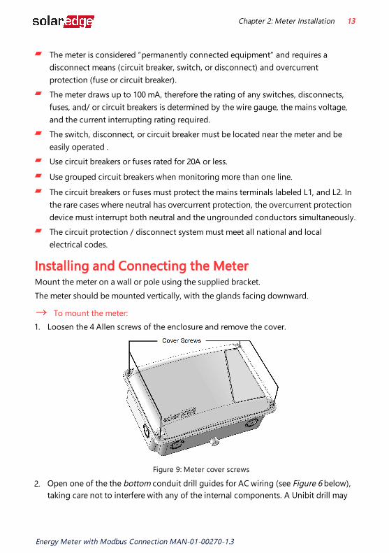
To mount the meter: 1. Loosen the 4 Allen screws of the enclosure and remove the cover.
Figure 9: Meter cover screws
2. Open one of the the bottom conduit drill guides for AC wiring (see Figure 6 below), taking care not to interfere with any of the internal components. A Unibit drill may
Chapter 2: Meter Installation 13
Energy Meter with Modbus Connection MAN-01-00270-1.3

be used. The rest of the drill guides (located at the bottom, back and sides of the enclosure, each with two sizes: ¾'' and 1'') should remain sealed.
Figure 10: AC wiring drill guide
3. Install the bracket on a wall or pole, with the semi-circles facing downward, as shown below. Verify that the bracket is firmly attached to the mounting surface.
Figure 11: Mounting bracket
4. Mount the meter: Attach the enclosure back brackets to the mounted bracket using the four supplied screws. Tighten the screws with a torque of 9 N*m / 6.6 lb*ft.
Figure 12: Back brackets
5. Open one or more conduit drill guides as required for the installation - each with two sizes: ¾'' and 1'', taking care not to interfere with any of the internal components. A Unibit drill may be used.
CAUTION!Use only drill guides located at the bottom, back and sides of the enclosure. Opening the top drill guides may damage the protection rating of the enclosure.
Energy Meter with Modbus Connection MAN-01-00270-1.3
14 Installing and Connecting the Meter

Figure 13: Meter - rear view
6. Mount the meter: Attach the meter enclosure's back brackets to the mounted bracket using the four supplied screws. Tighten the screws with a torque of 9 N*m / 6.6 lb*ft.
To install the current transformers (CTs):
CAUTION! NOTE
CTs are not supplied with the meter and must be purchased separately. Rogowski coils are not suitable for use with the meter.
1. Turn off AC power before clamping on current transformers. 2. Install the CTs around the conductor to be measured. Split-core CTs can be opened
for installation around a conductor. A nylon cable tie may be secured around the CT to prevent accidental opening.
3. Install the CTs with the arrows pointing to the grid for consumption or export measurement.
Chapter 2: Meter Installation 15
Energy Meter with Modbus Connection MAN-01-00270-1.3

To wire the meter:Wire the meter in accordance with one of the connection diagrams below:
Split phase grid, see the figure Split Phase Grid on page 16
No-neutral grid, see the figure No-Neutral Grid on page 17
If you are connecting the meter to a revenue grade inverter (inverter with built-in meter), refer to Installing Two Meters on page 35.
Figure 14: Split Phase Grid
NOTEClamp the CT connected to L1 CT around the wire connected to ØL1.Clamp the CT connected to L2 CT around the wire connected to ØL2.When clamping the CT around the conductor to be measured, make sure the arrow is pointing towards the grid.
Energy Meter with Modbus Connection MAN-01-00270-1.3
16 Installing and Connecting the Meter

Figure 15: No-Neutral Grid
NOTEClamp the CT connected to L1 CT around the wire connected to ØL1.When clamping the CT around the conductor to be measured, make sure the arrow is pointing towards the grid.
1. Verify that the meter is powered OFF before making connections. 2. Insert the grounding/neutral cable, AC-side wires, CT wires, and RS485 cabling
through the drill guide(s) that were opened and connect them to the meter as specified in the above diagrams.
3. Verify that the meter's termination DIP switches are set for "termination", as specified in the section "Termination DIP switches" on page 9.
4. Connect the RS485 wiring to the inverter or Commercial Gateway. To wire the inverter, see the procedure "connect the RS485 wiring to the inverter:" belowTo wire the Commercial Gateway, see the procedure "connect the RS485 wiring to the Commercial Gateway:" on page 19.
To connect the RS485 wiring to the inverter: 1. Remove the seal from one of the openings in communication gland #2 at the
bottom of the inverter and insert the RS485 wires from the meter through the opening.
Chapter 2: Meter Installation 17
Energy Meter with Modbus Connection MAN-01-00270-1.3

2. Prepare to connect the RS485 wiring to one of the available RS485 ports of the device. Note that some inverters have one RS485 port, some have two RS485 ports.
3. Pull out the RS485 connector located on the communication board, as shown in the figure below.
Figure 16: Inverter RS485 connection
4. Loosen the screws of RS485 terminal block pins B, A and G of the port you wish to connect.
Figure 17: RS485 terminal block
5. Insert the wire ends into the G, A and B pins shown above. Use Four- or six-wire twisted pair cable for this connection. You can use any color wire for each of the A, B and G connections, as long as:
The same color wire is used for all A pins the same color for all B pins and the same color for all G pinsThe wire for G is not from the same twisted pair as A or B.
6. Tighten the terminal block screws. 7. Push the RS485 terminal block firmly all the way into the communication board. 8. If the inverter is at the end of the RS485 bus, terminate by switching a termination
Energy Meter with Modbus Connection MAN-01-00270-1.3
18 Installing and Connecting the Meter

DIP-switch inside the inverter to ON (top position). The switch is located on the communication board and is marked SW7.
Figure 18: RS485 termination switch
To connect the RS485 wiring to the Commercial Gateway: 1. Connect to one of one of the 3-pin connectors supplied with the Commercial
Gateway to the RS485-2 connection on the Commercial Gateway.
Figure 19: Commercial Gateway RS485 connector
2. If the Commercial Gateway is at the end of the RS485 bus, terminate by switching the SW2 termnation DIP switch to ON.
Chapter 2: Meter Installation 19
Energy Meter with Modbus Connection MAN-01-00270-1.3

Figure 20: RS485 termination switch
Energy Meter with Modbus Connection MAN-01-00270-1.3
20 Installing and Connecting the Meter

Chapter 3: ConfigurationDevice ConfigurationThis section describes basic configuration of SolarEdge devices (inverter/Commercial Gateway) for use of a meter. In addition, a configuration that is specific to the application being used is required in some cases. Refer to the following documents:
Export Limitation - https://www.solaredge.com/sites/default/files/export_limitation_application_note_NA.pdfStorEdge Smart Energy Management off-grid applications - https://www.solaredge.com/files/pdfs/storedge_backup_installation_guide_NA.pdf.
NOTECalculated meter readings, such as self-consumption, are calculated using the data measured by the meter and the inverters. Calculated meter readings are only sent when Energy Manager is enabled (for details refer to https://www.solaredge.com/sites/default/files/export_limitation_application_note_NA.pdf).
Device Configuration using SetApp
NOTEMeter functionality is supported in inverters with CPU versions 4.2.xxx and above.
To configure the SolarEdge meter using SetApp: 1. From the SetApp main menu, select Communication, and select the port to which
the meter is connected - RS485-1 or RS485-2. 2. Select Protocol -> Modbus (Multi-Device) 3. Return to the RS485-x Menu and select Add Modbus Device -> Meter. A meter
identified as "Meter n" (where n = 1, 2, 3...) is created. The RS485-x Menu reappears. 4. Select Meter n. The RS485-x Meter n Menu appears. 5. Select Meter Function, and choose one of the following options:
Inverter Production: The meter is installed at the inverter output and reads the energy produced by the inverter.Export+Import: The meter is installed at the grid connection point and reads pulses from both directions - export and import energy.Consumption: The meter is installed at the load consumption point and reads the energy consumed by the site.
Chapter 3: Configuration 21
Energy Meter with Modbus Connection MAN-01-00270-1.3

Site Production: The meter is installed at the inverter output and reads the energy produced by inverters at the site.Ext. Production: The meter is used for export limitation with 3rd party generators and for AC coupling with non-SolarEdge inverters.
6. Select Meter Protocol, and select SolarEdge. 7. Select Device ID and enter the Modbus address corresponding to the ID DIP switch
settings on the meter. 8. Select CT Rating and enter the current transformer's rating in amperes. 9. Select Grid Topology and select Wye.
10. If relevant, select PT Scaling and set the potential transformer ratio. The default value is 1.
To verify the meter connection using SetApp: 1. From the SetApp main menu, select Status. 2. On the Status page, scroll down to the Communication section and view the current
connection state.
Meters
Export MeterRS485-2
Modbus ID #1Status
OKPower
7.60 kWEnergy
13.68 MWh
Device Configuration using the Device Display MenusTo operate the SolarEdge device menus:
Use the four user buttons to control the LCD panel menus:Esc: Moves the cursor (>) to the beginning of the currently displayed parameter; goes to the previous menu, and cancels a value change with a long press (until Aborted is displayed).Up (1) and Down (2): Moves the cursor from one menu option to another, moves among the characters of a displayed parameter, and toggles between possible characters when setting a value.
Energy Meter with Modbus Connection MAN-01-00270-1.3
22 Device Configuration

OK/Enter (3): Selects a menu option and accepts a value change with a long press (until Applied is displayed).
Use the three rightmost buttons Up, Down and OK sequentially for entering the Setup mode.
Inverter Configuration – Setup ModeAfter inverter installation, an installer may perform basic system configuration. Configuration is done when the inverter is in Setup mode.
To enter Setup mode: 1. Turn the inverter ON/OFF switch to OFF (AC remains ON).
WARNING!If the inverter was operating properly (power was produced by the power optimizers), the following message is displayed.
D C V O L T A G E N O T S A F ED O N O T D I S C O N N E C T V D C : 7 2 . 0
This message is displayed until the DC voltage is safe (50V). Do not open the lower cover until the voltage is safe or until at least five minutes have passed.
AVERTISSEMENT!
La tension de sécurité par défault est de 50V. Ne pas ouvrir le couvercle ou les connecteurs DC jusqu'à ce que la tension soit affichée comme sécurisé ou jusqu'à ce que cinq minutes au moins se soient écoulées.
2. Press the OK button for at least 5 seconds. The following message is displayed:P l e a s e e n t e r P a s s w o r d* * * * * * * *
3. Press the Up, Down and OK buttons (Up=1, Down=2, OK=3) for entering the Setup mode password: pq OK pqOK pq (12312312).
The inverter is now in Setup mode and all its LEDs are lit. The inverter automatically exits Setup mode if no buttons are pressed for more than 2 minutes.
Chapter 3: Configuration 23
Energy Meter with Modbus Connection MAN-01-00270-1.3
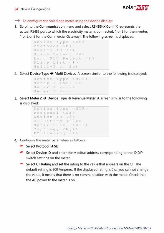
To configure the SolarEdge meter using the device display: 1. Scroll to the Communication menu and select RS485-X Conf (X represents the
actual RS485 port to which the electricity meter is connected: 1 or E for the inverter; 1 or 2 or E for the Commercial Gateway). The following screen is displayed:
D e v i c e T y p e < S E >P r o t o c o l < M >D e v i c e I D < 1 >S l a v e D e t e c t < # >L o n g S L V D e t e c t < # >S l a v e L i s t < # >M u l t i - I n v . S e t
2. Select Device Type è Multi Devices. A screen similar to the following is displayed:D e v i c e T y p e < M L T >M e t e r 1 < S E , 1 >M e t e r 2 < - - - >M e t e r 3 < - - - >
3. Select Meter 2 è Device Type è Revenue Meter. A screen similar to the following is displayed:
D e v i c e T y p e < M T R >P r o t o c o l < S E >D e v i c e I D < 2 >C T R a t i n g < 2 0 0 >M e t e r F u n c . < E + I >T o p o l o g y < W y e >P T S c a l i n g < 1 >
4. Configure the meter parameters as follows:Select Protocol èSE.
Select Device ID and enter the Modbus address corresponding to the ID DIP switch settings on the meter.Select CT Rating and set the rating to the value that appears on the CT. The default setting is 200 Amperes. If the displayed rating is 0 or you cannot change the value, it means that there is no communication with the meter. Check that the AC power to the meter is on.
Energy Meter with Modbus Connection MAN-01-00270-1.3
24 Device Configuration

Select Meter Func. and select one of the functionality options, according to the installed meter specifications and location.
E x p o r t + I m p o r tE x p o r tC o n s u m p t i o nP r o d u c t i o nE x t . P r o d u c t i o nI m p o r tN o n e
Export+Import: The meter is installed at the grid connection point and reads pulses from both directions - export and import energy.Export: The meter is installed at the grid connection point and reads the export energy.Consumption: The meter is installed at the load consumption point and reads the energy consumed by the site. Production: The meter is installed at the inverter output and reads the energy produced by the inverter.Ext. Production: The meter is used for export limitation with 3rd party generators and for AC coupling with non-SolarEdge inverters.Import: The meter is installed at the grid connection point and reads the import energy.None: No reading
The selected option is displayed in the RS485 Conf screen as <E+I>, <E>, <Cons>, <Prod>, <I>, <None>.
Topology: Select Wye.
If relevant, select PT Scaling and set the potential transformer ratio. The default value is 1.
5. Exit Setup mode.
NOTECalculated meter readings, such as self-consumption, are calculated using the data measured by the meter and the inverters. Calculated meters are only sent when Energy Manager is enabled (for details refer to https://www.solaredge.com/sites/default/files/export_limitation_application_note_NA.pdf).
Chapter 3: Configuration 25
Energy Meter with Modbus Connection MAN-01-00270-1.3

Verifying the Meter ConnectionVerifying the Meter Connection using SetApp
To verify the meter connection using SetApp: 1. From the SetApp main menu, select Status. 2. On the Status page, scroll down to the Communication status section. Check that
one or more meters is connected to the RS485-1 or RS485-2 bus.
Communication
LANConnected
RS485-1Modbus
2 of 2
RS485-2SE Slave None
CellularN/A
ZigBee
NC
3. Continue scrolling to the Meters section. If there is more than one meter/function, there is a status sub-section for each one. An example appears below. The following
Energy Meter with Modbus Connection MAN-01-00270-1.3
26 Device Configuration
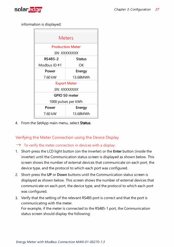
information is displayed:
MetersProduction Meter
SN: XXXXXXXX RS485-2
Modbus ID #1Status
OKPower
7.60 kWEnergy
13.68MWhExport Meter
SN: XXXXXXXXGPIO S0 meter
1000 pulses per kWhPower
7.60 kWEnergy
13.68MWh
4. From the SetApp main menu, select Status.
Verifying the Meter Connection using the Device Display
To verify the meter connection in devices with a display: 1. Short-press the LCD light button (on the inverter) or the Enter button (inside the
inverter) until the Communication status screen is displayed as shown below. This screen shows the number of external devices that communicate on each port, the device type, and the protocol to which each port was configured.
2. Short-press the UP or Down buttons until the Communication status screen is displayed as shown below. This screen shows the number of external devices that communicate on each port, the device type, and the protocol to which each port was configured.
3. Verify that the setting of the relevant RS485 port is correct and that the port is communicating with the meter.For example, if the meter is connected to the RS485-1 port, the Communication status screen should display the following:
Chapter 3: Configuration 27
Energy Meter with Modbus Connection MAN-01-00270-1.3

D e v P r o t # #R S 4 8 5 - 1 < M T R > < W N > < 1 >R S 4 8 5 - 2 < - - - > < - - > < - - >Z i g B e e < - - - > < - - > < - - >
Dev: the type of device connected to this port. MTR indicates a meter.Prot: the communication protocol## = 1: Indicates that the connection to the meter is successful.
4. Continue pressing the Enter button or the LIGHT button using short presses until reaching the meter status screen showing the Energy [Wh] total. If there is more than one meter/ function, there is a status screen for each one. The following is an example of an Export meter:
E x p o r t M e t e rS t a t u s : < O K / E r r o r # >P o w e r [ W ] : x x x x x . xE n e r g y [ W h ] : x x x x x . x
Status: Displays the state of communications between the meter and the inverter. Displays 'OK' if the meter is communicating with the inverter.
<Error message>: If an internal meter error occurs, it will be displayed here. Refer to Troubleshooting the Meter on page 29.
Power [W]: Displays the exported or imported power. Energy [Wh]: Displays the total energy read by the meter.
Energy Meter with Modbus Connection MAN-01-00270-1.3
28 Device Configuration
Appendix A: Troubleshooting the Meter This appendix describes how to troubleshoot meter-related installation and performance issues.
To troubleshoot the meter using SetApp, refer to Troubleshooting the Meter using SetApp on page 29.To troubleshoot the meter using the device display, refer to Troubleshooting the Meter using the Device Display on page 32.
Troubleshooting the Meter using SetApp
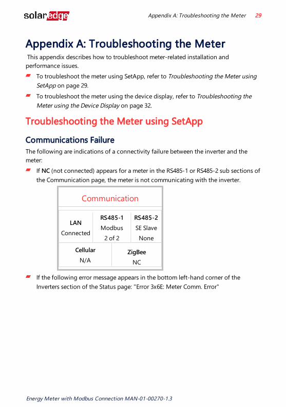
Communications FailureThe following are indications of a connectivity failure between the inverter and the meter:
If NC (not connected) appears for a meter in the RS485-1 or RS485-2 sub sections of the Communication page, the meter is not communicating with the inverter.
Communication
LANConnected
RS485-1Modbus
2 of 2
RS485-2SE Slave None
CellularN/A
ZigBee
NC
If the following error message appears in the bottom left-hand corner of the Inverters section of the Status page: "Error 3x6E: Meter Comm. Error"
Appendix A: Troubleshooting the Meter 29
Energy Meter with Modbus Connection MAN-01-00270-1.3

If the status in the Meters section of the Status page is "Comm. Error"
Meters
Export MeterRS485-1
Modbus ID #2Status
Comm. ErrorPower
7.60 kWEnergy
8.42 MWh
Check the following:
The meter's RS485 address DIP switch settings. Refer to "ID DIP switches" on page 8.
The meter's Termination DIP switch settings. Refer to "Termination DIP switches" on page 9.That the meter is configured as required in the chapter "Configuration" on page 21
The RS485 wiring between the meter and the inverter/Commercial Gateway as specified inTo connect the RS485 wiring to the inverter: on page 17There are no loose connections at the inverter connectors and at the meter, specifically the RS485 wiring. Check for water damage or sealing problems:
Inspect the entire conduit run for possible points of water penetration, and fix leaks.Ensure that proper outdoor rated components are used.
Use a Voltmeter to measure the voltage on the meter's AC wiring. The line to line voltage should be according to the meter's specifications.
Energy Meter with Modbus Connection MAN-01-00270-1.3
30 Troubleshooting the Meter using SetApp
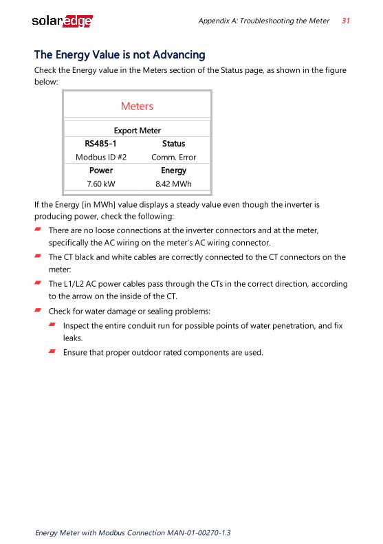
The Energy Value is not AdvancingCheck the Energy value in the Meters section of the Status page, as shown in the figure below:
Meters
Export MeterRS485-1
Modbus ID #2Status
Comm. ErrorPower
7.60 kWEnergy
8.42 MWh
If the Energy [in MWh] value displays a steady value even though the inverter is producing power, check the following:
There are no loose connections at the inverter connectors and at the meter, specifically the AC wiring on the meter's AC wiring connector. The CT black and white cables are correctly connected to the CT connectors on the meter:The L1/L2 AC power cables pass through the CTs in the correct direction, according to the arrow on the inside of the CT.
Check for water damage or sealing problems:Inspect the entire conduit run for possible points of water penetration, and fix leaks.Ensure that proper outdoor rated components are used.
Appendix A: Troubleshooting the Meter 31
Energy Meter with Modbus Connection MAN-01-00270-1.3

Troubleshooting the Meter using the Device Display The communication status screen should display the following:
D e v P r o t # #R S 4 8 5 - 1 < M T R > < S E > < 1 >R S 4 8 5 - 2 < - - - > < - - > < - - >Z i g B e e < - - - > < - - > < - - >
Device Type or Protocol are configured incorrectlyIf MTR (meter) is not displayed as the device type (DEV), or SE (SolarEdge) is not displayed as the Prot (protocol), configure the meter as follows.:
1. Select Communicationè RS485-x Conf è Device Type è Revenue Meter. 2. Select Communication è RS485-x Conf è Protocol è SolarEdge. 3. Check that the meter's Modbus address specified in Communication è RS485-x
Conf è Device ID corresponds to the meters' DIP switch settings. Refer to"ID DIP switches" on page 8.
4. Select Revenue Meter è Meter Func. è Export+Import / Export / Import / Consumption / Site Production / Inv. Production.
Number of devices is not displayedIf <--> is displayed under the ## column in the Communication status screen, the meter is not communicating with the inverter. Check the following:
The meter's ID DIP switch settings. Refer to "ID DIP switches" on page 8.
The meter's Termination DIP switch settings. Refer to "Termination DIP switches" on page 9.That the meter is configured as required in the chapter "Configuration" on page 21
The RS485 wiring between the meter and the inverter/Commercial Gateway as specified inTo connect the RS485 wiring to the inverter: on page 17There are no loose connections at the inverter connectors and at the meter, specifically the RS485 wiring. Check for water damage or sealing problems:
Inspect the entire conduit run for possible points of water penetration, and fix leaks.Ensure that proper outdoor rated components are used.
Energy Meter with Modbus Connection MAN-01-00270-1.3
32 Troubleshooting the Meter using the Device Display
Use a Voltmeter to measure the voltage on the meter's AC wiring. The line to line voltage should be according to the meter's specifications.
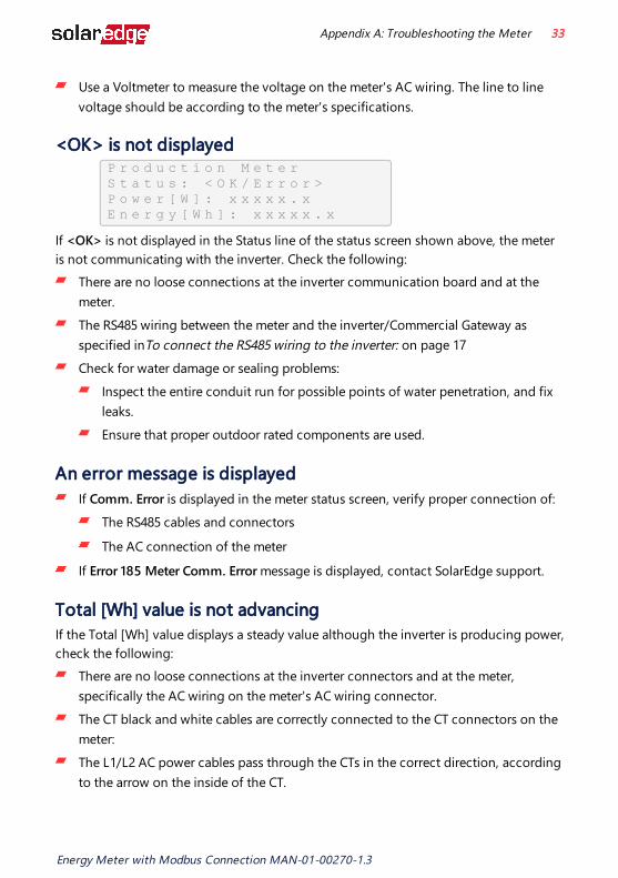
<OK> is not displayed P r o d u c t i o n M e t e rS t a t u s : < O K / E r r o r >P o w e r [ W ] : x x x x x . xE n e r g y [ W h ] : x x x x x . x
If <OK> is not displayed in the Status line of the status screen shown above, the meter is not communicating with the inverter. Check the following:
There are no loose connections at the inverter communication board and at the meter. The RS485 wiring between the meter and the inverter/Commercial Gateway as specified inTo connect the RS485 wiring to the inverter: on page 17Check for water damage or sealing problems:
Inspect the entire conduit run for possible points of water penetration, and fix leaks.Ensure that proper outdoor rated components are used.
An error message is displayedIf Comm. Error is displayed in the meter status screen, verify proper connection of:
The RS485 cables and connectors
The AC connection of the meter
If Error 185 Meter Comm. Error message is displayed, contact SolarEdge support.
Total [Wh] value is not advancingIf the Total [Wh] value displays a steady value although the inverter is producing power, check the following:
There are no loose connections at the inverter connectors and at the meter, specifically the AC wiring on the meter's AC wiring connector. The CT black and white cables are correctly connected to the CT connectors on the meter:The L1/L2 AC power cables pass through the CTs in the correct direction, according to the arrow on the inside of the CT.
Appendix A: Troubleshooting the Meter 33
Energy Meter with Modbus Connection MAN-01-00270-1.3

Check for water damage or sealing problems:Inspect the entire conduit run for possible points of water penetration, and fix leaks.Ensure that proper outdoor rated components are used.
Energy Meter with Modbus Connection MAN-01-00270-1.3
34 Troubleshooting the Meter using the Device Display

Appendix B: Installing Two MetersThis section describes connecting an external meter to an inverter equipped with a built-in Revenue Grade Meter (RGM), which is located in the inverter's Safety Switch.
Figure 21: Connecting an external meter to an inverter with a built-in RGM
Connecting Two Meters 1. Connect the external meter to the inverter as described in the section "wire the
meter:" on page 16. 2. Set the external meter's ID DIP switch settings. Refer to "ID DIP switches" on page 8.
3. Set the external Termination DIP switch settings. Refer to "Termination DIP switches" on page 9.
Configuring the Dual-Meter ConnectionTo configure the Dual-Meter connection using SetApp, refer to Configuring the Dual-Meter Connection on page 35.To configure the Dual-Meter connection using the device display, refer to Configuring Dual-Meter Connection Using the Device Display on page 36.
Configuring Dual-Meter Connection Using SetAppThe built-in RGM is pre-configured as a production meter and its settings should not be changed. Verify the pre-configured parameters of the RGM and configure the parameters of the external meter as described below.
1. From the SetApp main menu, select Communication è RS485-x è Meter 1 2. Verify the value of the following parameters:
Appendix B: Installing Two Meters 35
Energy Meter with Modbus Connection MAN-01-00270-1.3
Meter Function è Inverter Production
Protocol èSolarEdge
Device ID è 1
CT Rating è 5A
3. Select Meter 2 to configure the external meter in the following steps:
4. Select Meter Function, and choose one of the following options:Export+Import: The meter is installed at the grid connection point and reads pulses from both directions - export and import energy.Consumption: The meter is installed at the load consumption point and reads the energy consumed by the site. Site Production: The meter is installed at the inverter output and reads the energy produced by the inverters at the site.Ext. Production: The meter is used for export limitation with 3rd party generators and for AC coupling with non-SolarEdge inverters.
5. Select Meter Protocol, and select SolarEdge. 6. Set Device ID: 2. 7. Select CT Rating to set the CT rating to the value that appears on the CT. The default
is 5 Amperes. If the displayed rating is 0 or you cannot change the value, there is no communication with the meter. Check that the AC power to the meter is on.
8. Select Grid Topology and select Wye. 9. Select PT Scaling and set the potential transformer ratio.
Configuring Dual-Meter Connection Using the Device Display The built-in RGM is pre-configured as a production meter and its settings should not be changed. Verify the pre-configured parameters of the RGM and configure the parameters of the external meter as described below.
1. Verify that the inverter AC is turned ON. 2. If the meter is connected to an AC breaker, verify it is turned ON (the meter LEDs are
lit or blinking). 3. Enter Setup mode, scroll to the Communication menu and select Communication è RS485-x Conf. è Device Type è Multi Devices è Meter 1. The following is displayed for the RGM:
Energy Meter with Modbus Connection MAN-01-00270-1.3
36 Configuring the Dual-Meter Connection

D e v i c e T y p e < M T R >P r o t o c o l < W N >D e v i c e I D < 1 >C T R a t i n g < 5 A >M e t e r F u n c . < P r o d >
4. Verify:Device Type è MTR
Protocol è SE
Device ID è 1
CT Rating è 5A
Meter Func.è Prod (production)
5. Select Meter 2 and configure the external meter settings:Select Device Type è Revenue Meter
Select Protocol èSE
Set Device ID: 2
Set the CT rating to the value that appears on the CT: CT Rating è <xxxxA>. The default is 5 Amperes. If the displayed rating is 0 or you cannot change the value, there is no communication with the meter. Check that the AC power to the meter is on.Select Meter Func.è Inv. Production, Site Production, Consumption, Export, Import, or Export+Import.
Verifying the Meter ConnectionTo verify the Dual-Meter connection using SetApp, "Verifying Meter Connection using SetApp" on the next page.To verify the Dual-Meter connection using the device display, "Verifying Meter Connection Using the Device Display" on the next page.
Appendix B: Installing Two Meters 37
Energy Meter with Modbus Connection MAN-01-00270-1.3

Verifying Meter Connection using SetApp 1. From the SetApp main menu, select Status. 2. In the Communications section of the Status page, check the value of the RS485-x
field, which lists: The connection protocol (for example, Modbus, SE Master, SE Slave)
"x of y", where x is the number of meters configured, and y is the number of meters connected.
Verifying Meter Connection Using the Device Display 1. Press the Enter button or the LCD external button until the Communication status
screen is displayed as shown below. When two meters are connected, a screen similar to the following should appear:
D e v P r o t # #R S 4 8 5 - 1 < M L T > < 0 2 > < 0 2 >R S 4 8 5 - 2 < - - - > < - - > < - - >Z i g B e e < - - - > < - - > < - - >
Dev: The type of device configured to this port. MLT indicates multiple meters.Prot: The number of configured meters. For dual meters, it should display "02". If not, refer to Troubleshooting below.## : The number of communicating meters. For dual meters, it should display "02". If not, refer to Troubleshooting below.
2. Press the Enter button or the LCD external button until reaching the Meter status screen showing the total energy [Wh]. There is a status screen for each meter function. For example, for an export+import meter and a production meter, there will be three status screens: for export, import and production. The following is an example of an export meter:
E x p o r t M e t e rS t a t u s : < O K >< E r r o r M e s s a g e >T o t a l [ W h ] : X X X X X X X
Status: Displays OK if the meter is communicating with the communication board.<Error message>: If an internal meter error occurs, it will be displayed here. Refer to Troubleshooting the Meter on page 29.Total [Wh]: The amount of Watts per hour of the designated meter.
Energy Meter with Modbus Connection MAN-01-00270-1.3
38 Verifying the Meter Connection

If the SolarEdge device is connected to the SolarEdge server this value will also be displayed in the monitoring platform.
Troubleshooting the Dual-Meter Connection To troubleshoot the Dual-Meter connection using SetApp, Troubleshooting Dual-Meter Connection Using SetApp on page 39.To troubleshoot the Dual-Meter connection using the device display, Troubleshooting Dual-meter Connection using the Device Display on page 40.
Troubleshooting Dual-Meter Connection Using SetAppFor each of the meters installed, a dedicated Meters section should appear on the Status Page, as shown below:
Meters
Inverter Production MeterRS485-1
Modbus ID #1Status
OKPower
7.60 kWEnergy
13.68 MWh
Export MeterRS485-1
Modbus ID #2Status
OKPower
7.60 kWEnergy
8.42 MWh
If one or more of the meters is missing from the Meters section shown above, check the following:
The meters are configured as described in "Configuring the Dual-Meter Connection" on page 35There are no loose connections at the inverter connectors and at the meters, specifically the RS485 wiring.
Appendix B: Installing Two Meters 39
Energy Meter with Modbus Connection MAN-01-00270-1.3

The Energy value is not advancingCheck the Energy value in the Meters section of the Status page, as shown in the figure below:
Meters
Export MeterRS485-1
Modbus ID #2Status
Comm. ErrorPower
7.60 kWEnergy
8.42 MWh
If the Energy [in MWh] value displays a steady value even though the inverter is producing power, check the following:
There are no loose connections at the inverter connectors and at the meter, specifically the AC wiring on the meter's AC wiring connector. The CT black and white cables are correctly connected to the CT connectors on the meter:The L1/L2 cable passes through the CT in the correct direction, according to the arrow on the inside of the CT.
Check for water damage or sealing problems:Inspect the entire conduit run for possible points of water penetration, and fix leaks.Ensure that proper outdoor rated components are used.
Troubleshooting Dual-meter Connection using the Device DisplayCommunication Status Screen TroubleshootingWhen two meters are connected on the same RS485 bus, the following should appear in the Communication status screen:
D e v P r o t # #R S 4 8 5 - 1 < M L T > < 0 2 > < 0 2 >R S 4 8 5 - 2 < - - - > < - - > < - - >Z i g B e e < - - - > < - - > < - - >
Energy Meter with Modbus Connection MAN-01-00270-1.3
40 Troubleshooting the Dual-Meter Connection

Device Type or Protocol are configured incorrectlyIf MLT (Multi) is not displayed as the device type (DEV), or 2 is not displayed as the number of meters under Prot (protocol), configure the meters as follows:
1. Select Communication è RS485-x Conf è Device Type è Multi Devices. Select Device 1 or Device 2.
2. Select Communication è RS485-x Conf è Protocol è SE. 3. Select Revenue Meter è Meter Func. è Inv. Production, Site Production,
Consumption, Export, Import, or Export+Import.. 4. Check that the Device ID under Communication è RS485-x Conf è Device ID is
set to 1 or 2. Number of devices is lower than configured or not displayedIf <--> or <01> is displayed under the ## column in the Communication status screen shown above, at least one of the meters is not communicating with the inverter. Check the following:
The meter configuration is as described above.
There are no loose connections at the inverter connectors and at the meters, specifically the RS485 wiring.
Meter Status Screen TroubleshootingRefer to Troubleshooting the Meter on page 29.
Appendix B: Installing Two Meters 41
Energy Meter with Modbus Connection MAN-01-00270-1.3

Appendix C: Monitoring Platform - Meter DataIf your device is connected to the SolarEdge server, you can view the meter’s readings in the monitoring platform. Verify that the meter type is set correctly in the Admin page > Logical Layout > Meter details:
Figure 22: Setting the Meter details in the monitoring platform
Calculated meter readings (also referred to as "virtual meters"), such as self-consumption, are calculated using the data measured by the meter and the inverters.The data from the inverters and from installed meters is displayed in the Dashboard and Charts tabs of the monitoring platform. The displayed data depends on the meter(s) location: grid connection point (export), or load consumption point (consumption). The following tables detail the displayed information per meter location. Export meter:
Data Displayed inMonitoring Dashboard
Displayed in Monitoring Charts
Production (inverter/site) a aConsumption a(calculated) a(calculated)Self-consumption a(calculated) a(calculated)Export X a
Import X a
Consumption meter:
Data Displayed in Monitoring Dashboard
Displayed in Monitoring Charts
Production (inverter/site) a aConsumption a aSelf-consumption a(calculated) a(calculated)Export X a(calculated)Import X a(calculated)
Energy Meter with Modbus Connection MAN-01-00270-1.3
42 Appendix C: Monitoring Platform - Meter Data

Appendix D: External Lightning ProtectionProtection devices are most often installed from each data line to the local earth ground, and should be selected to begin conducting current at a voltage as close to the system's normal communication level as possible, but never lower. For RS485 communication lines, the selected voltage rating is typically 6-8 V. Transient suppressors should be installed as close as possible to the port that is being protected, and the user must provide an extremely low impedance connection to the local earth ground of the SolarEdge device. This ground connection is crucial for proper suppression device operation. The ground connection should be made using a heavy gauge wire and kept as short as possible. If the cable between the SolarEdge device and the protection device must be longer than 1m/3.3 ft., a copper strap or a braided cable intended for grounding purposes must be used for the protection device to be effective. In addition to the high frequency nature of transients, extremely high current may flow.A protective device with surge discharge ratings of In: 10kA 8/20μs and Imax: 20kA 8/20μs is recommended.For further information, see the Overvoltage Surge Protection Technical Note: https://www.solaredge.com/sites/default/files/lightning_surge_protection.pdf
Figure 23: Protection connection
Appendix D: External Lightning Protection 43
Energy Meter with Modbus Connection MAN-01-00270-1.3
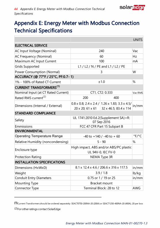
Appendix E: Energy Meter with Modbus Connection Technical Specifications
UNITSELECTRICAL SERVICEAC Input Voltage (Nominal) 240 VacAC Frequency (Nominal) 60 HzMaximum AC Input Current 100 mAGrids Supported L1 / L2 / N / PE and L1 / L2 / PE Power Consumption (Normal) 3 WACCURACY (@ 77°F / 25°C, PF:0.7- 1)1% - 100% of Rated CT Current ±1.0 %CURRENT TRANSFORMERS(1)
Nominal Input (at CT Rated Current) CT1, CT2: 0.333 Vac RMS Rated RMS current(2) 200 400
Dimensions (Internal / External) 0.8 x 0.8; 2.4 x 2.4 /20 x 20; 61 x 61
1.26 x 1.83; 3.3 x 4.5/32 x 46.5; 83.4 x 114
in/mm
STANDARD COMPLIANCE
Safety UL 1741:2010 Ed.2(Supplement SA)+R: 07 Sep 2016
Emmissions FCC 47 CFR Part 15 Subpart B ENVIRONMENTALOperating Temperature Range -40 to +140 / -40 to + 60 °F/°CRelative Humidity (noncondensing) 5 - 90 %
Enclosure typeHigh impact, ABS and/or ABS/PC plastic
UL 94V-0, IEC FV-0
Protection Rating NEMA Type 3R INSTALLATION SPECIFICATIONSDimensions (HxWxD) 8.1 x 12.4 x 4.6 / 206.6 x 316 x 117.5 in/mmWeight 3.9 / 1.8 lb/kgConduit Entry Diameters 0.75 or 1 / 19 or 25 in/mmMounting Type Bracket mount Connector Type Terminal Block: 28 to 12 AWG
(1)Current Transformers should be ordered separately: SEACT0750-200NA-20 (200A) or SEACT1250-400NA-20 (400A), 20 per box
(2)For other ratings contact SolarEdge
Energy Meter with Modbus Connection MAN-01-00270-1.3
44 Appendix E: Energy Meter with Modbus Connection TechnicalSpecifications

Support Contact InformationIf you have technical problems concerning SolarEdge products, please contact us:
https://www.solaredge.com/service/supportBefore contact, make sure to have the following information at hand:
Model and serial number of the product in question.
The error indicated on the product LCD screen or on the monitoring platform or by the LEDs, if there is such an indication.System configuration information, including the type and number of modules connected and the number and length of strings.The communication method to the SolarEdge server, if the site is connected.
The product's software version as it appears in the ID status screen.
Support Contact Information 45
Energy Meter with Modbus Connection MAN-01-00270-1.3
