installation catalog - truck bed, semi trailer tool boxes catalog quality built tool boxes ... never...
TRANSCRIPT

American Truckboxes, LLC., Installation Manual
Web Page: www.truckbox.com 2018 American Truckboxes, LLC. Made in USA Page 1
Welcome to American Truckboxes, LLC®, Manufacturers of
Installation
Catalog
Quality Built Tool Boxes
WWW.TRUCKBOX.COM
American Truckboxes, LLC., Installation Manual
Web Page: www.truckbox.com 2018 American Truckboxes, LLC. Made in USA Page 2
Index Page
No. Contents Page No. Contents Page 1. Step Boxes 3-4 12. Fuel Tanks Installation 15
2. Battery Boxes 4 13. Fuel Connection Kits Installation 16
3. In-Frame Boxes 5 14. Cross & Saddle Boxes 17
4. Deck Plates 6 15. Side Boxes 18
5. Rack Boxes 7 16. Rail Boxes 19
6. Underbody & Utility Boxes 8 17. 4-Wheeler Boxes 20
7. Cargo and Panel Boxes 9 18. Chest Dog Boxes 21
8. Under Deck Underbody Mount 10 19. L-Shape Mounting Brackets 22-26
9. Drawer Utility Boxes 11 20. Top Mount Brackets 27
10. Top Side Utility Boxes 12 21. BLB Bumper 28
11. Chest Boxes 13 22. Warranty & Special Notice 29
12. A-Frame Boxes 14 23.
Caution and Please Read Carefully Attention: Read and understand all instruction and warnings before installing and operating or using ATB product. Mounting box properly is
always very important. If done correctly, it will add longer life to your box. Always try to fasten box or brackets as parallel as possible, mount
box as high from the ground as possible.
Danger: Do not use ATB products for transporting or storing flammables, explosives, hazardous material, or hazardous waste, such as
containers of propane, gasoline, solvents, gun powder and acetylene. ATB products are designed and safe for use in storing and transporting
tools, equipment, and similar material. Any modification made to ATB products, or unintended use of ATB products, can or could create a
hazardous condition that can cause death, serious personal injury, or property damage.
Warning: Before mounting ATB products, use extra precautions on placement. ATB products can reduce driver's ability to clearly see
roadways, vehicular and pedestrian traffic, and other objects through the rear and side windows and mirrors of the vehicle. Make all
adjustments necessary to ensure maximum visibility. State and local laws may prohibit obstruction of windows in a moving vehicle.
Note: Before drilling, make sure all electrical wiring and components, fuel tank and associated components are not in the drilling
pattern.
Warning and Precautions!
A. Never Drill Top or Bottom Flange of Truck Frame or Trailer Frame.
B. Never Weld Mounting Brackets to Truck Frame or Trailer Frame.
C. Never Mount Through the Top of any Box.
Maintaining & Caring For Your Box.
1. Lubricate hinges and all moving lock parts periodically with
light household oil.
2. Check and tighten bolts periodically.
3. Check and replace worn-out weather stripping as needed.
4. Check and replace worn-out gas springs.
Notice
2. The Manufacturer has the right to make changes in
material and design at any time without notice.
3. Product design and fit are based on vehicle design
available at the revision date. Check product design or
contact your representative, distributor or American
Truckboxes, LLC to verify fitting of product design.
American Truckboxes, LLC
15750 6th Street SE
Blanchard, ND 58009
Web Page: www.truckbox.com
Email: [email protected]

American Truckboxes, LLC., Installation Manual
Web Page: www.truckbox.com 2018 American Truckboxes, LLC. Made in USA Page 3
SB10 Step Box Series.
Installation Time and Tools Required The approximate installation time is one (1.5) Hours; this is depending on installation experience.
1. ¾” Ratchet Wrench. 2. ¾” Wrench
3. Tape Measure
4. Drill & 9/16” or 11/16” Bit 5. Utility Knife
6. Blocks
Step Box Installation Mounting Instructions:
M3000H Installation Assembly Parts List
M3000C Installation Assembly Parts List
No. Item No. Part No. Description Qty.
No. Item No. Part No. Description Qty.
1 A SB10 Step Box N/A
1 A SB10 Step Box N/A
2 B MC1258 Hook ½” x 5/8” Stud” (Grade 8) 4
2 B BH858R17 Bolt ½” x 2” (Grade 8) 4
3 C WF858V16 Washer Flat 5/8” 4
3 C WF858R15 Washer Flat ½” 4
4 D R1803 Rubber 3” x 12” 2
4 D R1803 Rubber 3” x 12” 2
5 E NL858V Nut Lock 5/8” 4
5 E NL858R Nut Lock ½” 4
Installation Steps
Step 1: Check all parts by using the installation assembly parts list in this manual,
and make sure all parts are with package. Look over the area where the box should
be mounted to make sure that there is enough room to mount box.
Step 2: Remove all components from package and carefully move Box to
the frame where to be mounted to assure Box is mountable at that area. Holes
are not predrilled in Box due to variety of different hole patterns.
Step 3: Remove Box from mounting position. Drill four holes in back of Box as shown in drawings below (11/16” diameter for Figure 1 and 9/16” diameter for
Figure 2).
Internal MountingBrackets
Truck Frame Rail
Rear View of Step Box(Figure 2)
A
158"
158"
138" To Center
Hole
138" To Center
Hole
A
Top Step
M3000C Mounting Kit
Internal MountingBrackets
Truck Frame Rail
Rear View of Step Box(Figure 1)
158"
158"
138" To Center
Hole
138" To Center
Hole
Top Step
M3000H Mounting Kit
AA B
B
C
C
C = Box Width Minus 2-3/4"
CalculationsA = B Minus 3-1/4"
C = Box Width Minus 2-3/4"
Calculations
A = B Plus a 3/4"
Step 4: Relocate Box back to mounting position. For M3000H Kit, go
to step No. 6.
Step 5: Mark the predrilled holes, patterned on the Box you just drilled
to the frame where holes need to be drilled. Remove Box and drill four
9/16” diameter holes at each mark on the frame (refer to truck O.E.M.
shop manual for recommended frame drilling instructions).
Step 6: Apply the 3” strip of rubber material (d) to Box (as shown in
Drawing A or B). Cut drilled holes in the rubber you just applied, with
a utility knife and relocate Box to the frame. Insert Hooks or Bolts with
washers, through the holes (as shown on Drawing A or B). Place one
flat washer under a lock nut and tighten all nuts securely to complete
installation.
Drawing A:
Part Number: M3000H
Drawing B:
Part Number: M3000C
Note: This Step Box is designed with
internal mounting brackets; no
external brackets are required
providing the cargo weight will not
exceed 150 lbs.
Use M2000 or M2100 L-Shape
Mounting Brackets for Cargo
Weight over 150lbs.
Note. If spacing is required due
to bolts or brackets on truck
frame place an aluminum spacer
between box and truck frame and
longer bolts will need to be used.
Warning and Precautions! Never Drill Top or Bottom Flange of
Truck Frame or Trailer Frame.
Never Weld Mounting Brackets to Truck
Frame or Trailer Frame.
Never Mount Through the Top of any
Box

American Truckboxes, LLC., Installation Manual
Web Page: www.truckbox.com 2018 American Truckboxes, LLC. Made in USA Page 4
SB20 Step Boxes - BB4 & BS4 Battery Box Series.
Installation Time and Tools Required The approximate installation time is one & a half (1.5) Hour;
this is depending on installation experience.
1. 3/4” Ratchet/Wrench.
3. Drill - 1/2” & 5/8” Bit
2. 1-1/8” Ratchet/Wrench
4. Tape Measure & Square
Step Box & Battery Box Installation Mounting Instructions.
Installation Assembly Parts List No. Item
No.
Part No. Description Qty.
1 A SB20-BB4-BS4 Step or Battery Box N/A
2 B BH858V17 Bolt 5/8” x 2” 4
3 C BH858R17 Bolt ½” x 2” 6
4 D M3050 Mounting C-Frame L-Brackets Left/Right 2
5 E NL858R Nylon Lock Nut 1/2” 6
6 F NL858V Nylon Lock Nut 5/8” 4
7 G WF858R15 Washer 1/2” 12
8 H WF858V16 Washer 5/8” 8
Installation Steps
Step 1: Check all parts by using the installation assembly parts
list in this manual, and make sure all parts are with package.
Look over the area where the box should be mounted to make
sure that there is enough room to mount box.
Step 2: Remove all components from package and carefully
move Box to the frame where to be mounted to assure Box is
mountable at that area. Holes are predrilled on Box and Brackets
for easy and fast mounting.
Note: If L-brackets are already installed in truck frame, move to step five.
Step 3: Bolt on both L-brackets to box as shown on drawing A
with bolts, washers and nuts and tighten lightly.
Step 4 Move box up to frame, block under box where box is
mounting at the correct height, location and square box.
Step 5: Mark the four holes and relocated Box from mounting position. Check if holes are vertical and horizontal square. Drill all
four holes with 5/8” bit in Truck Frame (refer to truck O.E.M. shop manual for recommended drilling instructions).
Step 6: Clean frame and relocate Box to the frame or
mounting position. Insert all four bolts from Box side through
L-brackets and then through Frame.
Step 7: Place a lock nut on all four bolts. Tighten all nuts tightly
and secure to complete installation.
Drawing A:
Additional Warnings and Precautions!
1. Never Drill Top or Bottom Flange of
Truck Frame or Trailer Frame.
2. Never Weld Mounting Brackets to
Truck Frame or Trailer Frame.
3. Never Mount Through the Top or Back
of Toolboxes.
Drawing A:
Part Number: M3050C

American Truckboxes, LLC., Installation Manual
Web Page: www.truckbox.com 2018 American Truckboxes, LLC. Made in USA Page 5
IFB In-Frame Box Series.
Installation Time and Tools Required The approximate installation time is half (1/2) Hour; this is
depending on installation experience.
1. ½” Ratchet Wrench. 2. Utility Knife
In-Frame Box Installation Mounting Instructions.
Installation Assembly Parts List No. Item
No.
Part No. Description Qty.
1 A IFB3 In-Frame Box N/A
2 B BR577L13 Bolt Flange, Serrated 5/16” x 1” 4
3 C WF858L13 Washer Flat 5/16” 4
4 D R1802 Rubber 2” x 36” (36” is standard, may need to be cut to Box Depth) 2
5 E MC1530 Mounting Clamp 4
6 F NL858L Nylon Lock Nut 5/16” 4
Installation Steps
Step 1: Check all parts by using the installation assembly parts
list in this manual, and make sure all parts are with package.
Look over the area where the box should be mounted to make
sure that there is enough room to mount box.
Step 2: Remove all components from package and carefully
move Box to the frame where to be mounted to assure Box is
mountable at that area. Holes are predrilled on Box for easy and
fast mounting.
Step 3: Remove Box from mounting position. Cut rubber to Box Depth and apply the 3” strip of rubber material (to Box as shown
in Drawing A. Cut holes in the rubber with utility knife so bolts can be inserted. Insert all four bolts from Box side with washers
attached and attach a mounting clamp to each bolt, keep mounting clamp loose so that mounting clamps can freely be turned to
dismounted position or to one side. Relocate Box to the frame.
Step 4: Rotate all four mounting clamps (as shown in Drawing B) so that clamps are in mounting position or under frame. Lightly
tighten all four mounting clamps and make sure that the Box is perfectly secured, level and tight with frame. Tighten all bolts
tightly and secure to complete installation.
Drawing A:
Part Number: M3100F
Drawing B
Additional Warnings and Precautions!
1. Never Drill Top or Bottom Flange of
Truck Frame or Trailer Frame.
2. Never Weld Mounting Brackets to
Truck Frame or Trailer Frame.
3. Never Mount Through the Top or Back
of Toolboxes.
American Truckboxes, LLC., Installation Manual
Web Page: www.truckbox.com 2018 American Truckboxes, LLC. Made in USA Page 6
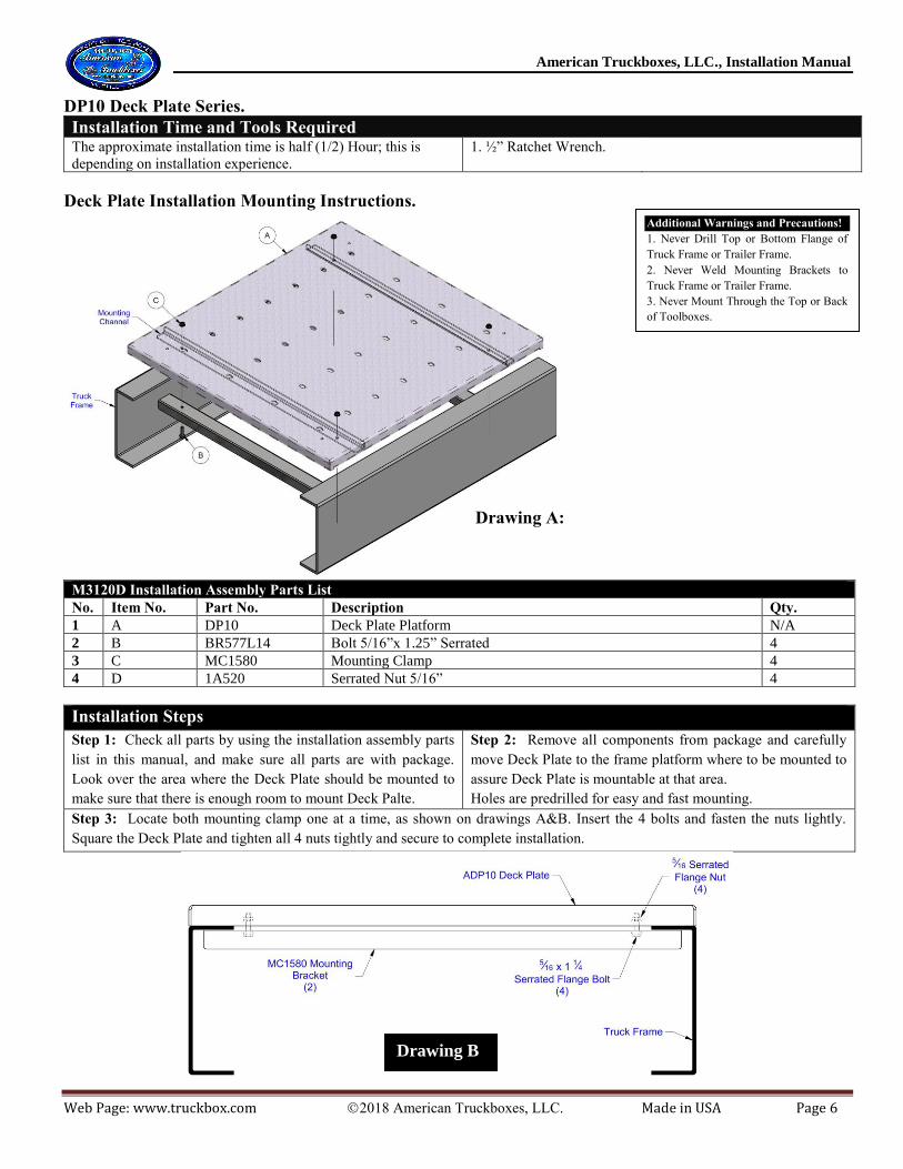
DP10 Deck Plate Series.
Installation Time and Tools Required The approximate installation time is half (1/2) Hour; this is
depending on installation experience.
1. ½” Ratchet Wrench.
Deck Plate Installation Mounting Instructions.
M3120D Installation Assembly Parts List
No. Item No. Part No. Description Qty.
1 A DP10 Deck Plate Platform N/A
2 B BR577L14 Bolt 5/16”x 1.25” Serrated 4
3 C MC1580 Mounting Clamp 4
4 D 1A520 Serrated Nut 5/16” 4
Installation Steps
Step 1: Check all parts by using the installation assembly parts
list in this manual, and make sure all parts are with package.
Look over the area where the Deck Plate should be mounted to
make sure that there is enough room to mount Deck Palte.
Step 2: Remove all components from package and carefully
move Deck Plate to the frame platform where to be mounted to
assure Deck Plate is mountable at that area.
Holes are predrilled for easy and fast mounting.
Step 3: Locate both mounting clamp one at a time, as shown on drawings A&B. Insert the 4 bolts and fasten the nuts lightly.
Square the Deck Plate and tighten all 4 nuts tightly and secure to complete installation.
Additional Warnings and Precautions!
1. Never Drill Top or Bottom Flange of
Truck Frame or Trailer Frame.
2. Never Weld Mounting Brackets to
Truck Frame or Trailer Frame.
3. Never Mount Through the Top or Back
of Toolboxes.
Drawing B
Drawing A:
American Truckboxes, LLC., Installation Manual
Web Page: www.truckbox.com 2018 American Truckboxes, LLC. Made in USA Page 7
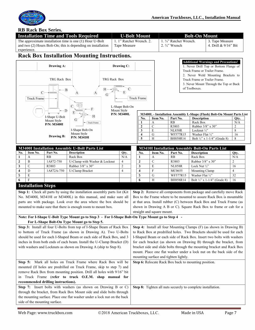
RB Rack Box Series.
Installation Time and Tools Required U-Bolt Mount Bolt-On Mount The approximate installation time is one (1) Hour U-Bolt
and two (2) Hours Bolt-On; this is depending on installation
experience.
1. 1” Ratchet Wrench. 2.
Tape Measure
1. ¾” Ratchet Wrench.
2. ¾” Wrench
3. Tape Measure
4. Drill & 9/16” Bit
Rack Box Installation Mounting Instructions.
M3400I Installation Assembly U-Bolt Parts List
M3410I Installation Assembly Bolt-On Parts List
No. Item No. Part No. Description Qty. No. Item No. Part No. Description Qty.
1 A RB Rack Box N/A
1 A RB Rack Box N/A
2 B 1A872-750 U-Clamp with Washer & Locknut 4
2 C R3803 Rubber 3/8” x 30” 2
3 C R3803 Rubber 3/8” x 30” 2
3 E NL858R Lock Nut ½” 16
4 D 1A872A-750 U-Clamp Bracket 4
4 F MC0655 Mounting Clamp 4
5 E
5 G WF577R15 Washer Flat ½” 32
6 F
6 H BH858R14 Bolt ½” x 1-1/4” (Grade 8) 16
Installation Steps
Step 1: Check all parts by using the installation assembly parts list (Kit
No. M3400I, M3410I or M3400L) in this manual, and make sure all
parts are with package. Look over the area where the box should be
mounted to make sure that there is enough room to mount box.
Step 2: Remove all components from package and carefully move Rack
Box to the Frame where to be mounted to assure Rack Box is mountable
at that area. Install rubber (C) between Rack Box and Truck Frame (as
shown in Drawing A B or C). Square Rack Box to frame or cab for a
straight and square mount.
Note: For I-Shape U-Bolt Type Mount go to Step 3 - For I-Shape Bolt-On Type Mount go to Step 4 -
For L-Shape Bolt-On Type Mount go to Step 5.
Step 3: Install all four U-Bolts from top of I-Shape Beam of Rack Box
to bottom of Truck Frame (as shown in Drawing A). Two U-Bolts
should be used for each I-Shaped Beam or each side of Rack Box, and 3
inches in from both ends of each beam. Install the U-Clamp Bracket (D)
with washers and Locknuts as shown on Drawing A (ship to Step 8).
Step 4: Install all four Mounting Clamps (F) (as shown in Drawing B)
to Rack Box at predrilled holes. Two Brackets should be used for each
I-Shaped Beam or each side of Rack Box. Insert two bolts with washers
for each bracket (as shown on Drawing B) through the bracket, from
bracket side and slide bolts through the mounting bracket and Rack Box
mount. Place one flat washer under a lock nut on the back side of the
mounting surface and tighten lightly.
Step 5: Mark all holes on Truck Frame where Rack Box will be
mounted (If holes are predrilled on Truck Frame, skip to step 7) and
remove Rack Box from mounting position. Drill all holes with 9/16” bit
in Truck Frame (refer to truck O.E.M. shop manual for
recommended drilling instructions).
Step 6: Relocate Rack Box back to mounting position.
Step 7: Insert bolts with washers (as shown on Drawing B or C)
through the bracket, from Rack Box Mount side and slide bolts through
the mounting surface. Place one flat washer under a lock nut on the back
side of the mounting surface.
Step 8: Tighten all nuts securely to complete installation.
B
Truck Frame Truck Frame
AH
CC
I-Shape U-Bolt Mount StyleP/N: M3400I
L-Shape Bolt-On Mount StyleP/N: M3400L
D
TRG Rack Box
EG
A
I-Shape Bolt-On Mount StyleP/N: M3410I
F
HG
E
C
TRG Rack Box
Truck Frame
Drawing A:
Drawing C:
Drawing B:
M3400L - Installation Assembly L-Shape (Flush) Bolt-On Mount Parts List
No. Item No. Part No. Description Qty.
1 A RB Rack Box N/A
2 C R3803 Rubber 3/8” x 30” 2
3 E NL858R Locknut ½” 8
4 G WF577R15 Washer Flat ½” 16
5 H BH858R14 Bolt ½” x 1-1/4” (Grade 8) 8
Additional Warnings and Precautions!
1. Never Drill Top or Bottom Flange of
Truck Frame or Trailer Frame.
2. Never Weld Mounting Brackets to
Truck Frame or Trailer Frame.
3. Never Mount Through the Top or Back
of Toolboxes.

American Truckboxes, LLC., Installation Manual
Web Page: www.truckbox.com 2018 American Truckboxes, LLC. Made in USA Page 8
20, 20RG, TRG, TRR Series Boxes.
Installation Time and Tools Required The approximate installation time is one (1) Hour; this is
depending on installation experience.
1. ½” Ratchet Wrench.
2. ½” Wrench
3. Tape Measure
4. Drill & 3/8” Bit
Trailer Box Installation Mounting Instructions.
Trailer Box Trailer Box
AFront View Side or End View
Mounting Trailer Box using C or I Frame Mount Kits.Recommended Kits : M2000 or M2100 Series
Truck Bed Truck Bed
Trailer Box
Trailer Box
Front View
Side or End View
Top Mount StyleP/N: M3200D
Truck Bed
Truck Bed
Drawing A:
Drawing C:
Mounting Trailer Box using Bed Mount Mounting Kits.Recommended Kits : M2200 Series
CB
D
E
F
E
F
F
Drawing B:
A
A
E
CB
DE
A
Box Front View Box Side or End View
2
1
Truck Bed Truck Bed
Truck Bed Support
B CD
B
C
3
B C
D
D
M22--D Installation Assembly Parts List (Drawing-A)
M3200D Installation Assembly Parts List (Drawing-B)
No. Item No. Part No. Description Qty.
No. Item No. Part No. Description Qty.
1 A Box Trailer Box N/A
1 A Box Trailer Box N/A
2 B BH577L13 Bolt 5/16” x 1” 8
2 C BH577L18F Bolt 5/16” x 2.25” 4
3 C WF267L13 Washer Flat 5/16” 16
3 E WF577L13 Washer Flat 5/16” 8
4 D NL577L Nut Lock 5/16” 8
4 F NL577L Nut Lock 5/16” 4
5 E M22--D Series Top Mounting Bracket 2
5 G R1803 Rubber 3” x Length of Box 2
M2000 or M2100 Installation Assembly Parts List (Drawing-C) No. Item No. Part No. Description Qty. No. Item No. Part No. Description Qty.
1 A Box Trailer Box N/A 4 D NL577L Nut Lock 5/16” 4
2 B BH577L13 Bolt 5/16” x 1” 4 5 E R1803 Rubber 3” x Length of Box 2
3 C WF267L13 Washer Flat 5/16” 8 6 F M2---- Series L Shape Mounting Bracket 2
Installation Steps
Step 1: Check all parts by using the installation assembly parts list in
this manual, and make sure all parts are with package. Look over the
area where the box should be mounted to make sure that there is enough
room to mount box.
Step 2: Remove all components from package and carefully move Box
to flat surface or mounting area where to be mounted to assure Box is
mountable at that area. Holes are not predrilled in Box due to variations
in mounting.
Note: Always drill hole as far to the outside edge of Box as possible.
Note: 1. For Bed Mount Mounting Application (Drawing A) use a M2200 Series Mounting Bracket, Install Mounting Bracket first and go to
step 5. Note 2. For Frame Mount Mounting Application (Drawing C) use a M2000 or M2100 Series Mounting Bracket, Install Mounting
Bracket first and go to step 5. Note 3: Installation Instruction for Mounting Brackets (optional) are with Bracket Mounting Kit.
Step 3: Remove Box from mounting position. Mark all four holes
outside on bottom of Box where box will be mounted to flat surface and
drill all four holes with 3/8” bit.
Step 4: Relocate Box back to mounting position. Mark the predrilled
holes, patterned on the Box you just drilled to the mounting surface
where holes need to be drilled and ship to step 6.
Step 5: Relocate Box back to mounting position. Mark the predrilled holes, patterned on the mounting brackets.
Step 6: Remove Box and drill four 3/8” diameter holes at each mark you
marked on the mounting surface or on Box (refer to truck O.E.M. shop
manual for recommended drilling instructions on surface).
Step 7: Insert bolts (B) with washers (C) (as shown on Drawings)
through the surface or bracket, from Box side and slide bolts through the
mounting surface. Place one flat washer under a lock nut on the back
side of the mounting surface or bracket and tighten all nuts securely to
complete installation.
Additional Warnings and
Precautions!
1. Never Drill Top or
Bottom Flange of Truck
Frame or Trailer Frame.
2. Never Weld Mounting
Brackets to Truck Frame or
Trailer Frame.
3. Never Mount Through
the Top or Back of
Toolboxes.

American Truckboxes, LLC., Installation Manual
Web Page: www.truckbox.com 2018 American Truckboxes, LLC. Made in USA Page 9
M2600UD Under Deck/Trailer Mounting Brackets.
Installation Time and Tools Required The approximate installation time is one and a half to Four (1.5 to 4.0) Hours; this
is depending on installation experience.
1. 3/4” Ratchet Wrench.
2. 3/4” Wrench 3. Tape Measure
4. Drill & 1/2” Bit
5. Two Clamps 6. Blocks
Under Deck/Trailer Adjustable Heavy Duty Aluminum Mounting Kit
Note: For none adjustable brackets use M2650UD
M2600UD-(Box Width(24”))-3 - Installation Kit Assembly for Underbody (Van Trailer) Bolt-On Mount Parts List: Item
No.
Part No. Description Qty.
1 M2610-ATB-(Width) Top Box Bracket 3
2 M2610-ABB-(Width) Bottom Box Bracket 3
3 Trailer I-Beam Cross Beam On Van Trailer 3
4 M2610-IB-12 Top I-Beam Clamp Bracket 6
5 M2610-CB-12 Top Center I-Beam Spacer Bracket 6
6 RODT-SS304T6-500 ½” Rod Bolt (Box Height + 4.5” Length) 6
7 NL858R ½” Nylon Lock Nut Grade 8 18
8 NH858R ½” Nut Grade 8 6
9 WF857R15 ½” Grade 8 Flat Washer 30
10 BH858R15 ½” x 1-1/2” Bolt Grade 8 6
Part Number Material Number of
Brackets
Weight Per Set
Load Rating
M2600UD Aluminum ¼” Thick 3 20 Lbs. *750 lbs. Max
M2600UD Aluminum ¼” Thick 5 30 Lbs. *1250 lbs. Max
Installation Steps
Step 1: Check all parts by using the installation assembly parts list in
this manual, and make sure all parts are with package. Look over the
area where the Box should be mounted to make sure that there is
enough room to mount Box.
Step 2: Remove all components from package and carefully move
Cargo Box to the underbody mounted position where the Cargo Box is
to be mounted to check if Box is mountable at that area.
Note: Drawing A shows one set of Bracket Assembly. Standard Bracket Kit comes with three Bracket Assemblies like shown in Drawing
A and can be order with five.
Step 3: Relocate Box to the side and install Washer (item 9) and
Locknut (item 7) on Rod (item 6) and tighten till thread shows ¼” past
Nut (item 7). Slide Rod through Top Bracket and install Top Clamp
Bracket (item 4) between Trailer I-beams as shown on Drawing A.
Repeat for all six brackets first before continuing to next step.
Note: Install three Bracket Sets as shown in Drawing A for weight of
750lbs and 5 for 1250lbs (See note at chart). Outside Brackets should
be installed as far to outside of trailer as possible and one in the center.
Step 4: Next locate Top Bracket (item 1) and Top Center Clamp
(item 5) and install as shown in Drawing A. Insert Bolt (item 10) in
place with washer (item 9) on both ends of Bolt and secure Nylon
Lock Nut (Item 7).
Step 5: Locate Nut (item 8) and Secure Nut as shown in Drawing A.
Step 6: Relocate Box in mounted position and place blocks under
Box to hold in place.
Step 7: Add Bottom Brackets (item 2) in position as shown in Drawing
A. Add Washers (item 9) and Nylon Lock Nut (Item 7) and Secure Nut.
Drawing A:
Additional Warnings and Precautions!
1. Never Drill Top or Bottom Flange of
Truck Frame or Trailer Frame.
2. Never Weld Mounting Brackets to
Truck Frame or Trailer Frame.
3. Never Mount Through the Top or Back
of Toolboxes.

American Truckboxes, LLC., Installation Manual
Web Page: www.truckbox.com 2018 American Truckboxes, LLC. Made in USA Page 10
M2700UD Under Deck/Trailer Mounting Brackets.
Installation Time and Tools Required The approximate installation time is one and a half to Four (1.5 to 4.0) Hours; this
is depending on installation experience.
1. 3/4” Ratchet Wrench.
2. 3/4” Wrench 3. Tape Measure
4. Drill & 1/2” Bit
5. Two Clamps 6. Blocks
Under Deck/Trailer Adjustable Heavy Duty Aluminum Mounting Kit
M2700UD-(Box Depth(24”))-2 - Installation Kit Assembly for Underbody (Van Trailer) Bolt-On Mount Parts List:
Item
No.
Part No. Description Qty.
1 M2710-ATB-(Width) Top Box Bracket 4
2 M2710-ABB-(Depth) Bottom Box Bracket (Box Depth -2”) 2
3 Trailer I-Beam Cross Beam On Van Trailer N/A-4
4 M2710-IB-12 Top I-Beam Clamp Bracket 4
5 M2710-CB-12 Top Center I-Beam Spacer Bracket 4
6 RODT-SS304T6-500 ½” Rod Bolt (Box Height + 4.5” Length) 4
7 NL858R ½” Nylon Lock Nut Grade 8 12
8 NH858R ½” Nut Grade 8 4
9 WF857R15 ½” Grade 8 Flat Washer 20
10 BH858R16 ½” x 1-3/4” Bolt Grade 8 4
Part Number Material Number of
Brackets
Weight Per Set
Load Rating
M2700UD Aluminum ¼” Thick 2 20 Lbs. *250 lbs. Max
M2700UD Aluminum ¼” Thick 3 30 Lbs. *350 lbs. Max
Installation Steps
Step 1: Check all parts by using the installation assembly parts list in
this manual, and make sure all parts are with package. Look over the
area where the Box should be mounted to make sure that there is
enough room to mount Box.
Step 2: Remove all components from package and carefully move
Cargo Box to the underbody mounted position where the Cargo Box is
to be mounted to check if Box is mountable at that area. Mark holes
where Rods will go through box, mainly on the front top and bottom of
box. Drill holes with ½” drill.
Note: Drawing A shows one set of Bracket Assembly. Standard Bracket Kit comes with two Bracket Assemblies like shown in Drawing
A and can be order with more for Double Door Wider Boxes.
Step 3: Relocate Box to the side and install Washer (item 9) and
Locknut (item 7) on Rod (item 6) and tighten till thread shows ¼” past
Nut (item 7). Slide Rod through Top Bracket and install Top Clamp
Bracket (item 4) between Trailer I-beams as shown on Drawing A.
Repeat for all six brackets first before continuing to next step.
Step 4: Relocate Box in mounted position and install rods through box
drilled holes and place blocks under Box to hold in place.
Note: Install Two Bracket Sets as shown in Drawing A for weight of
250lbs and 3 for 350lbs (See note at chart). Brackets should be installed
as far to outside of trailer as possible and one in the center for double
drop open door boxes.
Step 5: Next locate Top Bracket (item 1) and Top Center Clamp
(item 5) and install as shown in Drawing A. Insert Bolt (item 10) in
place with washer (item 9) on both ends of Bolt and secure Nylon
Lock Nut (Item 7).
Step 6: Locate Nut (item 8) and Secure Nut as shown in Drawing A.
Add Bottom Brackets (item 2) in position as shown in Drawing A and
Add Washers (item 9) and Nylon Lock Nut (Item 7) and Secure Nut.
Additional Warnings and Precautions!
1. Never Drill Top or Bottom Flange of
Truck Frame or Trailer Frame.
2. Never Weld Mounting Brackets to
Truck Frame or Trailer Frame.
3. Never Mount Through the Top or Back
of Toolboxes.
Note: For none adjustable
brackets use M2750UD
American Truckboxes, LLC., Installation Manual
Web Page: www.truckbox.com 2018 American Truckboxes, LLC. Made in USA Page 11
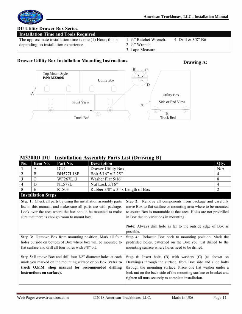
DU Utility Drawer Box Series.
Installation Time and Tools Required The approximate installation time is one (1) Hour; this is
depending on installation experience.
1. ½” Ratchet Wrench.
2. ½” Wrench
3. Tape Measure
4. Drill & 3/8” Bit
Drawer Utility Box Installation Mounting Instructions.
Utility Box
Utility Box
Front View Side or End View
Top Mount StyleP/N: M3200D
Truck Bed Truck BedE
Drawing A:
A
A
E
CB
D
M3200D-DU - Installation Assembly Parts List (Drawing B) No. Item No. Part No. Description Qty.
1 A DU4 Drawer Utility Box N/A
2 B BH577L18F Bolt 5/16” x 2.25” 4
3 C WF267L13 Washer Flat 5/16” 8
4 D NL577L Nut Lock 5/16” 4
5 E R1803 Rubber 3/8” x 3” x Length of Box 2
Installation Steps
Step 1: Check all parts by using the installation assembly parts
list in this manual, and make sure all parts are with package.
Look over the area where the box should be mounted to make
sure that there is enough room to mount box.
Step 2: Remove all components from package and carefully
move Box to flat surface or mounting area where to be mounted
to assure Box is mountable at that area. Holes are not predrilled
in Box due to variations in mounting.
Note: Always drill hole as far to the outside edge of Box as
possible.
Step 3: Remove Box from mounting position. Mark all four
holes outside on bottom of Box where box will be mounted to
flat surface and drill all four holes with 3/8” bit.
Step 4: Relocate Box back to mounting position. Mark the
predrilled holes, patterned on the Box you just drilled to the
mounting surface where holes need to be drilled.
Step 5: Remove Box and drill four 3/8” diameter holes at each
mark you marked on the mounting surface or on Box (refer to
truck O.E.M. shop manual for recommended drilling
instructions on surface).
Step 6: Insert bolts (B) with washers (C) (as shown on
Drawings) through the surface, from Box side and slide bolts
through the mounting surface. Place one flat washer under a
lock nut on the back side of the mounting surface or bracket and
tighten all nuts securely to complete installation.
Drawing A:

American Truckboxes, LLC., Installation Manual
Web Page: www.truckbox.com 2018 American Truckboxes, LLC. Made in USA Page 12
CU41 Top Side Mount Compartment Utility Box Series.
Installation Time and Tools Required The approximate installation time is two (2) Hours per box; this
is depending on installation experience.
1. ½” Ratchet Wrench.
2. ½” Wrench
3. Tape Measure
4. Drill with 3/8” Bit
5. Square
6. 5/16” drill Tip
Compartment Utility Box Installation Mounting Instructions
Box
Side Rail Mount StyleP/N: M3500T
P/N: M3500TT
Truckbox
www.truckbox.com
Rubber
MountingPad
Rubber MountingPad
A
FC
H
G
C
EI
F
Utility Box
Side or EndView
Truck BedBack View
E
Utility Box
Side or EndView
E
A
C
F
D
Cross Top Brackets
B
C
F
D
J K
Note: M3500T comes without the Cross Top Brackets
M3500T & M3500TT- Installation Assembly Parts List No. Item No. Part No. Description Qty. (M3500T) Qty. (M3500TT)
1 A CU4 Compartment Utility Box N/A N/A
2 B Truck Box Truck box N/A N/A
3 C WF267L13 Washer Flat 5/16” 22 32
4 D R1803 Rubber 3” x Width of Box 1 N/A
5 E NL577L Nut Lock 5/16” 11 16
6 F BH577L13 Bolt 5/16” x 1” 11 16
7 G SH577K14 Screw Self Drilling #14 x 1.5” 6 N/A
8 H 1A320 Upper Mounting Side Bracket 2 N/A
9 I 1A320-1 Lower Mounting Side Bracket 2 N/A
10 J 1A324 Cross Top Bracket (Inner-Smaller) N/A 2
11 K 1A324-1 Cross Top Bracket (Outer-Bigger) N/A 2
Installation Steps Step 1: Check all parts by using the installation assembly parts list in this manual, and
make sure all parts are with package. Look over the area where the Box should be
mounted to make sure that there is enough room to mount Box.
Step 2: Remove all components from package and carefully move Box to top
rail position behind the cab where the box is to be mounted to assure Box is
mountable at that area and square box.
Step 3: Measure and/or mark the rail area under the box. Remove Box from mounting
position and flip box over. Mark three places to drill holes for mounting box center on
rail, (check truck rail if drillable in that area), and drill each hole in box. Apply the 3”
strip of rubber material on marked Box mounting surface as shown in Drawing A.
Step 4: Relocate Box back to mounting position on top of rails. Support Box by
shimming small pieces of wood between Box and truck box fender. Mark all
holes on truck rail, drilled in box and drill holes through truck rail, if need
relocate box to drill truck rail.
Step 5: Insert all three bolts from inside Box (as shown in drawing B). Attach two
washers, one on each sides and lock nut to each bolt and tighten all nuts securely.
Step 6: Assemble both side brackets (I & H) (with two bolts each) as shown in
Drawing C. Hold and square brackets to mounting position and mark top holes
(two each) on Box back (two mounting brackets as required per box).
Step 7: Drill holes with a 3/8” bit. Install bolts (as shown in drawing C), square bracket
and tighten bolts. Install the three self-drilling screws on bottom of each bracket. If
boxes are mounted on both side of truck, repeat steps 1 thru step 7 for 2nd box and then
move on to step 8. If an over the cab ladder rack is installed on pickup truck, top of
boxes can be bolted to rack and M3500TT brackets can be eliminated.
Step 8: If cross top brackets are used - Assemble both top brackets (J & K) (with
four bolts each) as shown in Drawing A. Hold and square brackets to mounting
position and mark all four holes (two each end of brackets) on Box back (two top
brackets as required per installation).
Step 9: Remove brackets and drill holes with a 3/8” bit. Install bolts (as shown in drawing A), and tighten all nuts securely.
Notes.
1. If your pickup truck is fitted with a plastic bed liner it may need to be trimmed, drilled or cut for proper installation of box. 2. Use touch-up paint on any drilled holes to prevent oxidation or rust.
3. Mounting clamp bolts may be difficult to turn or tighten due to locknut feature. Apply a small amount of grease (oil) to bolt before installing for ease
assembly
Drawing A:
Drawing C:
Additional Warnings and Precautions!
1. Never mount or drill through top of
box.
Drawing B:

American Truckboxes, LLC., Installation Manual
Web Page: www.truckbox.com 2018 American Truckboxes, LLC. Made in USA Page 13
TC Chest Box Series.
Installation Time and Tools Required The approximate installation time is a half (1/2) Hour; this
is depending on installation experience.
1. ½” Ratchet Wrench.
2. ½” Wrench
3. Tape Measure
4. Drill & 3/8” Bit
Chest Box Installation Mounting Instructions.
Front View Side or End View
Truck Bed Truck BedE
AA
E
CB
D
M3200D Series - Installation Assembly Parts List
No. Item No. Part No. Description Qty.
1 A TC Chest Box N/A
2 B BH577L18F Bolt 5/16” x 2.25” 4
3 C WF267L13 Washer Flat 5/16” 8
4 D NL577L Nut Lock 5/16” 4
5 E R1802 Rubber 2” x Length of Box 2
Installation Steps
Step 1: Check all parts by using the installation assembly
parts list in this manual, and make sure all parts are with
package. Look over the area where the box should be
mounted to make sure that there is enough room to mount
box.
Step 2: Remove all components from package and
carefully move Box to the flat surface where to be
mounted to assure Box is mountable at that area. Holes
are not predrilled in Box due to variations in mounting.
Note: Always drill hole as far to the outside edge of
Box as possible.
Step 3: Remove Box from mounting position. Mark all
four holes outside on bottom of Box where box will be
mounted to flat surface and drill all four holes with 3/8”
bit.
Step 4: Relocate Box back to mounting position. Mark
the predrilled holes, patterned on the Box you just
drilled to the mounting surface where holes need to be
drilled.
Step 5: Remove Box and drill four 3/8” diameter holes at
each mark on the mounting surface (refer to truck
O.E.M. shop manual for recommended drilling
instructions).
Step 6: Insert bolts with washers (as shown on
Drawing A) through the bracket, from Box side and
slide bolts through the mounting surface. Place one flat
washer under a lock nut on the back side of the
mounting surface and tighten all nuts securely to
complete installation.
Drawing A:
American Truckboxes, LLC., Installation Manual
Web Page: www.truckbox.com 2018 American Truckboxes, LLC. Made in USA Page 14
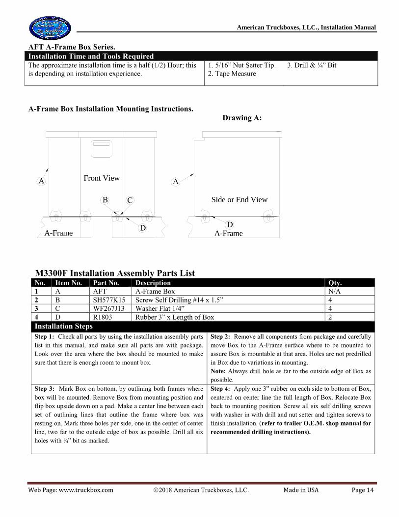
AFT A-Frame Box Series.
Installation Time and Tools Required The approximate installation time is a half (1/2) Hour; this
is depending on installation experience.
1. 5/16” Nut Setter Tip.
2. Tape Measure
3. Drill & ¼” Bit
A-Frame Box Installation Mounting Instructions.
Front View
Side or End View
A-Frame A-FrameD
AA
D
CB
M3300F Installation Assembly Parts List No. Item No. Part No. Description Qty.
1 A AFT A-Frame Box N/A
2 B SH577K15 Screw Self Drilling #14 x 1.5” 4
3 C WF267J13 Washer Flat 1/4” 4
4 D R1803 Rubber 3” x Length of Box 2
Installation Steps
Step 1: Check all parts by using the installation assembly parts
list in this manual, and make sure all parts are with package.
Look over the area where the box should be mounted to make
sure that there is enough room to mount box.
Step 2: Remove all components from package and carefully
move Box to the A-Frame surface where to be mounted to
assure Box is mountable at that area. Holes are not predrilled
in Box due to variations in mounting.
Note: Always drill hole as far to the outside edge of Box as
possible.
Step 3: Mark Box on bottom, by outlining both frames where
box will be mounted. Remove Box from mounting position and
flip box upside down on a pad. Make a center line between each
set of outlining lines that outline the frame where box was
resting on. Mark three holes per side, one in the center of center
line, two far to the outside edge of box as possible. Drill all six
holes with ¼” bit as marked.
Step 4: Apply one 3” rubber on each side to bottom of Box,
centered on center line the full length of Box. Relocate Box
back to mounting position. Screw all six self drilling screws
with washer in with drill and nut setter and tighten screws to
finish installation. (refer to trailer O.E.M. shop manual for
recommended drilling instructions).
Drawing A:

American Truckboxes, LLC., Installation Manual
Web Page: www.truckbox.com 2018 American Truckboxes, LLC. Made in USA Page 15
TS, TL & TT Series Auxiliary Fuel Tank
Installation Time and Tools Required The approximate installation time is two (1) Hours; this
is depending on installation experience.
1. Ratchet Wrench.
2. Wrench
3. Drill & Bit
4. Tape Measure
Auxiliary Tank Installation Instructions.
M3712-TMK Kit M3715-TMK Kit
No. Item Part No. Description Qty. Part No. Description Qty.
1 A Tank Fuel Tank/Box N/A Tank Fuel Tank/Box N/A
2 B BH858N22 3/8” x 3-1/4” Bolt 4 BH858N24 1/2” x 3-3/4” Bolt 4
3 C WF214N12 3/8” Washer 8 WF214R13 1/2” Washer 8
4 D NL858N 3/8” Lock Nut 4 NL858R 1/2” Lock Nut 4
5 E 1A827-S12 Spring 4 1A827-S15 Spring 4
6 F 1A827-B12 3/8” (5/8”) Bushing 4 1A827-B15 1/2” (3/4”) Bushing 4
Installation Steps Step 1: Check all parts by using the installation assembly parts
listed and make sure all parts are with package.
Step 2: Look over the area where the Tank should be mounted to
make sure that there is enough room to mount Tank and how to
best install the Tank
Step 3: Remove all components from package and locate Tank
where it is to be mounted to assure Tank is mountable at that
area. If Tank has a tool box make sure lid can open.
Step 4: Square Tank and mark the four holes on truck bed where
the Tank is to be mounted. Check truck wiring and hoses under
bed if none are path of your marked holes.
Step 5: Relocate the Tank to the side and drill all four holes in
truck bed. The holes size will depend on the mounting kit (see
chart above).
Step 6: After drilling the holes, clean the box from drilling debris
or dirt. Cut the 2” neoprene to the same length as tank depth and
apply to the truck box ridges on top part at four different locations.
Note: For installing Fuel Tank Kit, see Tank Kit Installation Sheet.
Step 7: Relocate tank back to mounting position and install the
bolts, washers, bushings, springs, and nuts as shown on drawing
Option 1 or Drawing B.
Step 8: Tighten all the nuts firmly. This should allow the tank to
anchored to the floor and still be able to shift if the truck box
twists
Notes. Use touch-up paint on any drilled holes to prevent oxidation or rust Caution: 1. Use an aluminum or light weight pump on aluminum Tanks, using a heavy pump can damage tank! 2. Never mount fuel
Tank directly to truck frame, or without the spring-loaded kit, for this can case tank failure and will void Tank warranty.
Drawing A:
Drawing B:
American Truckboxes, LLC., Installation Manual
Web Page: www.truckbox.com 2018 American Truckboxes, LLC. Made in USA Page 16
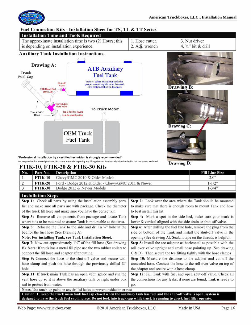
Fuel Connection Kits - Installation Sheet for TS, TL & TT Series
Installation Time and Tools Required The approximate installation time is two (2) Hours; this
is depending on installation experience.
1. Hose cutter.
2. Adj. wrench
3. Nut driver
4. ¾” bit & drill
Auxiliary Tank Installation Instructions.
“Professional installation by a certified technician is strongly recommended” Not responsible for altered products. No claims are made regarding any lifting devices. Any and all claims implied in this document excluded.
FTIK-10, FTIK-20 & FTIK-30 Kits No. Part No. Description Fill Line Size
1 FTIK-10 Chevy/GMC 2010 & Older Models 2.0”
2 FTIK-20 Ford - Dodge 2012 & Older - Chevy/GMC 2011 & Newer 1-1/2”
3 FTIK-30 Dodge 2013 & Newer Models 1-3/4”
Installation Steps Step 1: Check all parts by using the installation assembly parts
list and make sure all parts are with package. Check the diameter
of the truck fill hose and make sure you have the correct kit.
Step 2: Look over the area where the Tank should be mounted
to make sure that there is enough room to mount Tank and how
to best install this kit
Step 3: Remove all components from package and locate Tank
where it is to be mounted to assure Tank is mountable at that area.
Step 4: Mark a spot in the side bed, make sure your mark is
lower & vertical aligned with the side drain or shut-off valve.
Step 5: Relocate the Tank to the side and drill a ¾” hole in the
bed for the fuel hose (See Drawing A).
Note: For installing Tank, see Tank Installation Sheet.
Step 6: After drilling the fuel line hole, remove the plug from the
side or bottom of the Tank and install the shut-off valve in the
opening (See drawing A). Sealant tape on the threads is helpful.
Step 7: Now cut approximately 1½” of the fill hose (See drawing
B). Note: If truck has a metal fill pipe use the two rubber collars to
connect the fill hose and adaptor after cutting.
Step 8: Install the tee adaptor as horizontal as possible with the
roll over valve upright and small hose pointing up (See drawing
C & D). Then secure the tee fitting tightly with the hose clamps
Step 9: Connect the hose to the shut-off valve and secure with
hose clamp and push the hose through the previously drilled ¾”
hole.
Step 10: Measure the distance to the adapter and cut off the
unneeded hose. Connect the hose to the roll over valve on top of
the adapter and secure with a hose clamp.
Step 11: If truck main Tank has an open vent, splice and run the
vent hose up so it is above the auxiliary tank or right under box
rail to protect from water.
Step 12: Fill Tank with fuel and open shut-off valve. Check all
the connections for any leaks, if none are found, Tank is ready to
go.
Notes. Use touch-up paint on any drilled holes to prevent oxidation or rust
Caution: 1. Keep the truck main tank fuel cap closed when the auxiliary tank has fuel and the shut-off valve is open, system is
designed to have the truck fuel cap in place. Do not look into truck cap while truck is running to check fuel filler operate.
Drawing A:
American Truckboxes, LLC., Installation Manual
Web Page: www.truckbox.com 2018 American Truckboxes, LLC. Made in USA Page 17
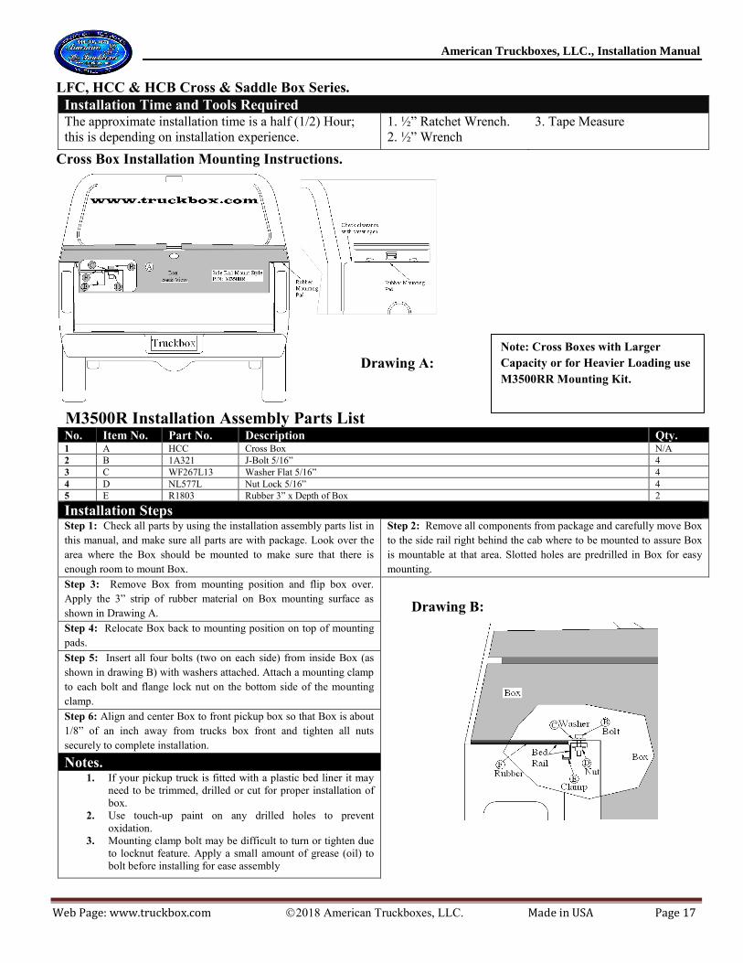
LFC, HCC & HCB Cross & Saddle Box Series.
Installation Time and Tools Required The approximate installation time is a half (1/2) Hour;
this is depending on installation experience.
1. ½” Ratchet Wrench.
2. ½” Wrench
3. Tape Measure
Cross Box Installation Mounting Instructions.
M3500R Installation Assembly Parts List No. Item No. Part No. Description Qty. 1 A HCC Cross Box N/A
2 B 1A321 J-Bolt 5/16” 4
3 C WF267L13 Washer Flat 5/16” 4
4 D NL577L Nut Lock 5/16” 4
5 E R1803 Rubber 3” x Depth of Box 2
Installation Steps Step 1: Check all parts by using the installation assembly parts list in
this manual, and make sure all parts are with package. Look over the
area where the Box should be mounted to make sure that there is
enough room to mount Box.
Step 2: Remove all components from package and carefully move Box
to the side rail right behind the cab where to be mounted to assure Box
is mountable at that area. Slotted holes are predrilled in Box for easy
mounting.
Step 3: Remove Box from mounting position and flip box over.
Apply the 3” strip of rubber material on Box mounting surface as
shown in Drawing A.
Step 4: Relocate Box back to mounting position on top of mounting
pads.
Step 5: Insert all four bolts (two on each side) from inside Box (as
shown in drawing B) with washers attached. Attach a mounting clamp
to each bolt and flange lock nut on the bottom side of the mounting
clamp.
Step 6: Align and center Box to front pickup box so that Box is about
1/8” of an inch away from trucks box front and tighten all nuts
securely to complete installation.
Notes. 1. If your pickup truck is fitted with a plastic bed liner it may
need to be trimmed, drilled or cut for proper installation of
box.
2. Use touch-up paint on any drilled holes to prevent
oxidation.
3. Mounting clamp bolt may be difficult to turn or tighten due
to locknut feature. Apply a small amount of grease (oil) to
bolt before installing for ease assembly
Drawing A:
Drawing B:
Note: Cross Boxes with Larger
Capacity or for Heavier Loading use
M3500RR Mounting Kit.

American Truckboxes, LLC., Installation Manual
Web Page: www.truckbox.com 2018 American Truckboxes, LLC. Made in USA Page 18
LFS, HCS, MCS Side Box Series.
Installation Time and Tools Required The approximate installation time is one (1) Hour per box; this is
depending on installation experience.
1. ½” Ratchet Wrench.
2. ½” Wrench
3. Tape Measure
4. Drill with 3/8” Bit
5. Square
6. 5/16” drill Tip
Side Box Installation Mounting Instructions.
Box
Back View
D
C
Side Rail Mount StyleP/N: M3530R
Truckbox
www.truckbox.com
B
E
F
A
RubberMountingPad
Rubber MountingPad
Check clearance with cover open
A
BC
I
H
C
GJ
M3530R Installation Assembly Parts List
No. Item No. Part No. Description Qty. 1 A HCS or MSC Side Box N/A
2 B 1A321 J-Bolt 5/16” 3
3 C WF267L13 Washer Flat 5/16” 19
4 D R1803 Rubber 3” x Width of Box 1
5 E 1A520 Nut Serrated 5/16” 7
6 F BH577L13 Bolt 5/16” x 1” 4
7 G SH577515 Screw Self Drilling #14 x 1” 6
8 H 1A320 Upper Mounting Side Bracket 2
9 I 1A320-1 Lower Mounting Side Bracket 2
Installation Steps Step 1: Check all parts by using the installation assembly parts list in this manual,
and make sure all parts are with package. Look over the area where the Box should
be mounted to make sure that there is enough room to mount Box.
Step 2: Remove all components from package and carefully move Box to
the side rail right behind the cab where to be mounted to assure Box is
mountable at that area. Slotted holes are predrilled in Box for easy
mounting.
Step 3: Remove Box from mounting position and flip box over. Apply
the 3” strip of rubber material on Box mounting surface as shown in
Drawing A.
Step 4: Relocate Box back to mounting position on top of
mounting pads. Support Box by shimming small pieces of wood
between Box and truck box fender.
Step 5: Insert all three bolts from inside Box (as shown in drawing B) with washers
attached. Attach a mounting clamp to each bolt and a Flange lock nut on the
bottom side of the mounting clamp.
Step 6: Align and center Box to front pickup box so that Box is about 1/8” of an
inch away from trucks box front and tighten all nuts securely.
Step 7: Assemble both side mounting brackets (I) (with two bolts each) as shown
in Drawing A. Hold and square brackets to mounting position and mark top holes
(two each) on Side Box (two mounting brackets as required, one in front and one in
the back. Front bracket can be mounted on the inside).
Step 8: Drill holes with a 3/8” bit. Install bolts (as shown in drawing A), square
bracket and tighten bolts. Install the two self drilling screws on bottom of each
bracket, with drill to finish installation.
Notes. 1. If your pickup truck is fitted with a plastic bed liner it may need to be trimmed,
drilled or cut for proper installation of box.
2. Use touch-up paint on any drilled holes to prevent oxidation.
3. Mounting clamp bolt may be difficult to turn or tighten due to locknut feature.
Apply a small amount of grease (oil) to bolt before installing for ease assembly
Drawing A:
Drawing B:
American Truckboxes, LLC., Installation Manual
Web Page: www.truckbox.com 2018 American Truckboxes, LLC. Made in USA Page 19
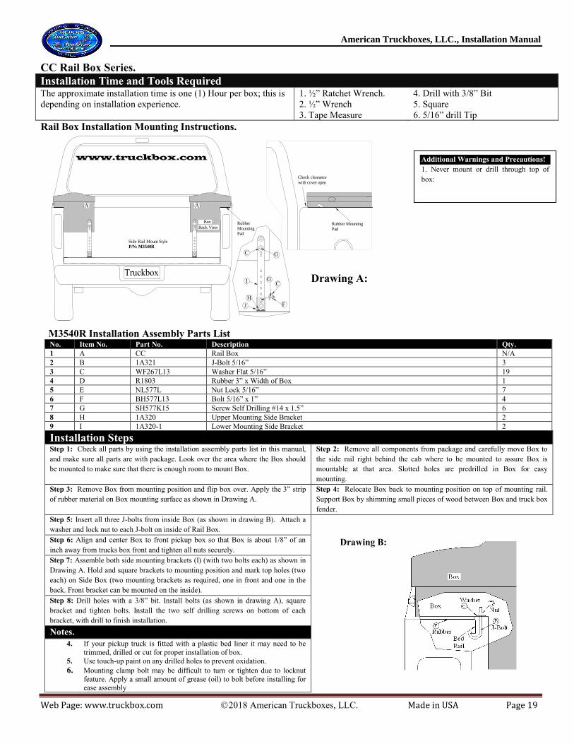
CC Rail Box Series.
Installation Time and Tools Required The approximate installation time is one (1) Hour per box; this is
depending on installation experience.
1. ½” Ratchet Wrench.
2. ½” Wrench
3. Tape Measure
4. Drill with 3/8” Bit
5. Square
6. 5/16” drill Tip
Rail Box Installation Mounting Instructions.
Box
Back View
Side Rail Mount StyleP/N: M3540R
Truckbox
www.truckbox.com
RubberMountingPad
Rubber MountingPad
Check clearancewith cover open
A A
GC
I
H
C
FJ
G
M3540R Installation Assembly Parts List
No. Item No. Part No. Description Qty.
1 A CC Rail Box N/A
2 B 1A321 J-Bolt 5/16” 3
3 C WF267L13 Washer Flat 5/16” 19
4 D R1803 Rubber 3” x Width of Box 1
5 E NL577L Nut Lock 5/16” 7
6 F BH577L13 Bolt 5/16” x 1” 4
7 G SH577K15 Screw Self Drilling #14 x 1.5” 6
8 H 1A320 Upper Mounting Side Bracket 2
9 I 1A320-1 Lower Mounting Side Bracket 2
Installation Steps Step 1: Check all parts by using the installation assembly parts list in this manual,
and make sure all parts are with package. Look over the area where the Box should
be mounted to make sure that there is enough room to mount Box.
Step 2: Remove all components from package and carefully move Box to
the side rail right behind the cab where to be mounted to assure Box is
mountable at that area. Slotted holes are predrilled in Box for easy
mounting.
Step 3: Remove Box from mounting position and flip box over. Apply the 3” strip
of rubber material on Box mounting surface as shown in Drawing A.
Step 4: Relocate Box back to mounting position on top of mounting rail.
Support Box by shimming small pieces of wood between Box and truck box
fender.
Step 5: Insert all three J-bolts from inside Box (as shown in drawing B). Attach a
washer and lock nut to each J-bolt on inside of Rail Box.
Step 6: Align and center Box to front pickup box so that Box is about 1/8” of an
inch away from trucks box front and tighten all nuts securely.
Step 7: Assemble both side mounting brackets (I) (with two bolts each) as shown in
Drawing A. Hold and square brackets to mounting position and mark top holes (two
each) on Side Box (two mounting brackets as required, one in front and one in the
back. Front bracket can be mounted on the inside).
Step 8: Drill holes with a 3/8” bit. Install bolts (as shown in drawing A), square
bracket and tighten bolts. Install the two self drilling screws on bottom of each
bracket, with drill to finish installation.
Notes.
4. If your pickup truck is fitted with a plastic bed liner it may need to be
trimmed, drilled or cut for proper installation of box.
5. Use touch-up paint on any drilled holes to prevent oxidation.
6. Mounting clamp bolt may be difficult to turn or tighten due to locknut
feature. Apply a small amount of grease (oil) to bolt before installing for ease assembly
Drawing A:
Drawing B:
Additional Warnings and Precautions!
1. Never mount or drill through top of
box:

American Truckboxes, LLC., Installation Manual
Web Page: www.truckbox.com 2018 American Truckboxes, LLC. Made in USA Page 20
SC 4-Wheeler Box Series.
Installation Time and Tools Required The approximate installation time is a half (1/2) Hour; this
is depending on installation experience.
1. T-30 Torx Driver.
2. 7/16” Wrench
3. Tape Measure
2. Drill with 5/16” Bit
4-Wheeler Box, Installation Mounting Instructions.
Front ViewSide or End ViewSC Box
AA
CB
DE
M3202D Installation Assembly Parts List No. Item No. Part No. Description Qty.
1 A SC 4-Wheeler Box N/A
2 B 1A480 Screw Torx 1/4” x 3/4” Stainless Steel 4
3 C WF267J13 Washer Flat 1/4” Stainless Steel 8
4 D 1A490 Nut Lock ¼” Stainless Steel 4
5. E R18150 1/8” x 1.5” Rubber 2
Installation Steps
Step 1: Check all parts by using the installation assembly
parts list in this manual, and make sure all parts are with
package.
Step 2: Remove all components from package. Carefully move
Box on to 4-Wheeler front or back rack or at mounting area and
square Box.
Holes are not predrilled in Box.
Step 3: Mark all four holes and mounting rails, using a pen or
marker from bottom of Box by using the predrilled mounting
holes on the 4-Wheeler Rack. Remove Box and drill all four
holes with 5/16” bit. Apply rubber on bottom of Box where
mounting rails are marked from front to back or side to side.
Step 4: Relocate Box back to mounting position. Insert bolts
with washers (as shown on Drawing A) through the inside of
Box side and slide bolts through the Box and 4-Wheeler Rack.
Place one flat washer under a lock nut on the bottom of 4-
Wheeler Rack and tighten all nuts securely to complete
installation.
Drawing A:

American Truckboxes, LLC., Installation Manual
Web Page: www.truckbox.com 2018 American Truckboxes, LLC. Made in USA Page 21
TC Chest Dog Box Series.
Installation Time and Tools Required The approximate installation time is a half (1/2) Hour; this
is depending on installation experience.
1. Torx T-30 river.
2. Drill with 5/16” Bit
Chest Dog Box Installation Mounting Instructions.
Front View
Side or End View
Dog Box Dog Box
AA
BC
M3200D-DB Installation Assembly Parts List No. Item No. Part No. Description Qty.
1 A TC31 Chest Dog Box N/A
2 B 1A480 Screw Torx 1/4” x 1/2” Stainless Steel 4
3 C WF214J13 Washer Flat 1/4” Stainless Steel 4
4. D 1A490 Nylon Lock Nut 1/4” 4
Installation Steps
Step 1: Check all parts by using the installation assembly parts
list in this manual, and make sure all parts are with package.
Step 2: Remove all components from package and carefully
move Box on to Dog Box top and square Box.
Note: Holes are not predrilled in Dog Box.
Step 3: Mark all four holes on Dog Box by using the hole
pattern on bottom of Chest Box.
Step 4: Remove Box and drill a 5/16” diameter hole at each
marked point on top of Dog Box.
Step 5: Relocated Chest Box and install all screws with washers (as shown on Drawing A) through the inside of Dog Box and
tighten all nuts securely to complete installation.
Drawing A:
American Truckboxes, LLC., Installation Manual
Web Page: www.truckbox.com 2018 American Truckboxes, LLC. Made in USA Page 22
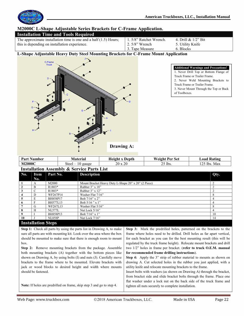
M2000C L-Shape Adjustable Series Brackets for C-Frame Application.
Installation Time and Tools Required The approximate installation time is one and a half (1.5) Hours;
this is depending on installation experience.
1. 5/8” Ratchet Wrench.
2. 5/8” Wrench
3. Tape Measure
4. Drill & 1/2” Bit
5. Utility Knife
6. Blocks
L-Shape Adjustable Heavy Duty Steel Mounting Brackets for C-Frame Mount Application
Part Number Material Height x Depth Weight Per Set Load Rating
M2000C Steel – 10 gauge 20 x 20 25 lbs. 125 lbs. Max
Installation Assembly & Service Parts List No. Item
No.
Part No. Description Qty.
1 A M2000 Mount Bracket Heavy Duty L-Shape 20” x 20” (2 Piece) 2
2 B R1803* Rubber 3” x 18” 2
3 C R1803* Rubber 3” x 12” 2
4 D WF267P14 Washer Flat 7/16” 8
5 E BH858P17 Bolt 7/16” x 2” 4
6 F BH577L13 Bolt 5/16 ” x 1” 4
7 G WF267L13 Washer Flat 5/16” 8
8 H NL577L Nut Lock 5/16” 4
9 I BH858P13 Bolt 7/16” x 1” 10
10 J NL858P Nut Lock 7/16” 14
Installation Steps
Step 1: Check all parts by using the parts list in Drawing A, to make
sure all parts are with mounting kit. Look over the area where the box
should be mounted to make sure that there is enough room to mount
box.
Step 2: Remove mounting brackets from the package. Assemble
both mounting brackets (A) together with the bottom pieces like
shown on Drawing A, by using bolts (I) and nuts (J). Carefully move
brackets to the frame where to be mounted. Elevate brackets with
jack or wood blocks to desired height and width where mounts
should be fastened.
Note: If holes are predrilled on frame, skip step 3 and go to step 4.
Step 3: Mark the predrilled holes, patterned on the brackets to the
frame where holes need to be drilled. Drill holes as far apart vertical,
for each bracket as you can for the best mounting result (this will be
regulated by the truck frame height). Relocate mount brackets and drill
two 1/2” holes in frame per bracket. (refer to truck O.E.M. manual
for recommended frame drilling instructions).
Step 4: Apply the 3” strip of rubber material to mounts as shown on
drawing A. Cut selected holes in the rubber you just applied, with a
utility knife and relocate mounting brackets to the frame.
Insert bolts with washers (as shown on Drawing A) through the bracket,
from bracket side and slide bracket bolts through the frame. Place one
flat washer under a lock nut on the back side of the truck frame and
tighten all nuts securely to complete installation.
Drawing A:
Additional Warnings and Precautions!
1. Never Drill Top or Bottom Flange of
Truck Frame or Trailer Frame.
2. Never Weld Mounting Brackets to
Truck Frame or Trailer Frame.
3. Never Mount Through the Top or Back
of Toolboxes.

American Truckboxes, LLC., Installation Manual
Web Page: www.truckbox.com 2018 American Truckboxes, LLC. Made in USA Page 23
M2000I L-Shape Adjustable Series Brackets for I-Frame Application.
Installation Time and Tools Required The approximate installation time is one and a half (1.5) Hours;
this is depending on installation experience.
1. 5/8” Ratchet Wrench.
2. 5/8” Wrench
3. Tape Measure
4. Drill & ½” Bit
5. Utility Knife
6. Blocks
L-Shape Adjustable Heavy Duty Steel Mounting Brackets for I-Frame Mount Application
Part Number Material Height x Depth Weight Per Set Load Rating
M2000I Steel – 10 gauge 20 x 20 27 lbs. 125 lbs. Max
Installation Assembly & Service Parts List No. Item
No.
Part No. Description Qty.
1 A M2000 Mount Bracket Heavy Duty L-Shape 20” x 20” (2 Piece) 2
2 B R1803* Rubber 3” x 18” 2
3 C WF267P14 Washer Flat 7/16” 8
4 D BH858P29 Bolt 7/16” x 5” 4
5 E BH577L13 Bolt 5/16 ” x 1” 4
6 F WF267L13 Washer Flat 5/16” 8
7 G NL577L Nut Lock 5/16” 4
8 H BH858P13 Bolt 7/16” x 1” 10
9 I NL858P Nut Lock 7/16” 14
10 J MS2504 Spacer 2.5” x 3.5” Square 4
Installation Steps
Step 1: Check all parts by using the parts list in Drawing A, to make
sure all parts are with mounting kit. Look over the area where the box
should be mounted to make sure that there is enough room to mount
box.
Step 2: Remove mounting brackets from the package. Assemble
both mounting brackets (A) together with the bottom pieces like
shown on Drawing A, by using bolts (I) and nuts (J). Carefully move
brackets to the frame where to be mounted. Elevate brackets with
jack or wood blocks to desired height and width where mounts
should be fastened.
Note: If holes are predrilled on frame, skip step 3 and go to step 4.
Step 3: Mark the predrilled holes, patterned on the brackets to the
frame where holes need to be drilled. Drill holes as far apart vertical,
for each bracket as you can for the best mounting result (this will be
regulated by the truck frame height). Relocate mount brackets and drill
two 1/2” holes in frame per bracket. (refer to truck O.E.M. manual
for recommended frame drilling instructions).
Step 4: Apply the 3” strip of rubber material to mounts as shown on
drawing A. Cut selected holes in the rubber you just applied, with a
utility knife and relocate mounting brackets to the frame.
Insert bolts with washers (as shown on Drawing A) through the bracket,
from bracket side. Slide bushings on bolts (as shown in Drawing A) and
slide brackets bolts through the frame. Place one flat washer under a
lock nut on the back side of the truck frame and tighten all nuts securely
to complete installation.
Drawing A:
Additional Warnings and Precautions!
1. Never Drill Top or Bottom Flange of
Truck Frame or Trailer Frame.
2. Never Weld Mounting Brackets to
Truck Frame or Trailer Frame.
3. Never Mount Through the Top or Back
of Toolboxes.

American Truckboxes, LLC., Installation Manual
Web Page: www.truckbox.com 2018 American Truckboxes, LLC. Made in USA Page 24
M2050 L-Shape Series Brackets for C-Frame Application.
Installation Time and Tools Required The approximate installation time is one and a half (1.5) Hours;
this is depending on installation experience.
1. ¾” Ratchet Wrench.
2. ¾” Wrench
3. Tape Measure
4. Drill & 9/16” Bit
5. Utility Knife
6. Blocks
L-Shape Super Heavy Duty Steel Mounting Brackets for C-Frame Mount Application
Part Number Material Height x Depth Weight Per Set Load Rating
M2050C Steel – 1/8 gauge 20” x 20” 28 lbs. 300 lbs. Max
M2050C Installation Assembly & Service Parts List. No. Item
No.
Part No. Description Qty.
1 A M2050 Mount Bracket Heavy Duty L-Shape 18” x 18” (Set Left/Right) 1
2 B R1803* Rubber 3” x 18” * This item comes in a roll and will need to be cut to length. 2
3 C R1803* Rubber 3” x 12” * This item comes in a roll and will need to be cut to length. 2
4 D WF266P17 Washer Flat 7/16” 4
5 E BH858P15 Bolt 7/16” x 1-1/2” 4
7 F BH577L13 Bolt 5/16 ” x 1” 4
8 G WF267L13 Washer Flat 5/16” 8
9 H NL577L Nut Lock 5/16” 4
10 I WF267P14 Washer Flat 7/16” 4
11 J NL858P Nut Lock 7/16” 4
13 K L-CB40S Cross Beam (Optional) N/A
Installation Steps
Step 1: Check all parts by using the parts list in Drawing A, to make
sure all parts are with mounting kit. Look over the area where the box
should be mounted to make sure that there is enough room to mount
box.
Step 2: Remove mounting brackets from the package and carefully
move to the frame where to be mounted. Elevate brackets with jack
or wood blocks to desired height and width where mounts should be
fastened.
Note: If holes are predrilled on frame, skip step 3 and go to step 4.
Step 3: Mark the predrilled holes, patterned on the brackets to the
frame where holes need to be drilled. Drill holes as far apart vertical,
for each bracket as you can for the best mounting result (this will be
regulated by the truck frame height). Relocate mount brackets and drill
two 9/16” holes in frame per bracket. (refer to truck O.E.M. manual
for recommended frame drilling instructions).
Step 4: Apply the 3” strip of rubber material to mounts as shown on
drawing A. Cut selected holes in the rubber you just applied with a
utility knife and relocate mounting brackets to the frame.
Insert bolts with washers (as shown on Drawing A) from bracket side
(use big heavy washer), through the mounting bracket and then through
the frame. Place one flat washer under a lock nut on the back side of the
truck frame and tighten all nuts securely to complete installation.
Drawing A:
Additional Warnings and Precautions!
1. Never Drill Top or Bottom Flange of
Truck Frame or Trailer Frame.
2. Never Weld Mounting Brackets to
Truck Frame or Trailer Frame.
3. Never Mount Through the Top or Back
of Toolboxes.

American Truckboxes, LLC., Installation Manual
Web Page: www.truckbox.com 2018 American Truckboxes, LLC. Made in USA Page 25
M2100C L-Shape Series Brackets for C-Frame Application.
Installation Time and Tools Required The approximate installation time is one and a half (1.5) Hours;
this is depending on installation experience.
1. ¾” Ratchet Wrench.
2. ¾” Wrench
3. Tape Measure
4. Drill & 9/16” Bit
5. Utility Knife
6. Blocks
L-Shape Super Heavy Duty Steel Mounting Brackets for C-Frame Mount Application
Part Number Material Height x Depth Weight Per Set Load Rating
M2100C Steel - 3/16 gauge 28” x 25” 42 lbs. 500 lbs. Max
M2101C Steel - 1/4 gauge 28” x 25” 54 lbs. 700 lbs. Max
M2102C Steel - 1/4 gauge 36” x 34” 72 lbs. 700 lbs. Max
M2110C Aluminum - 1/4 gauge 28” x 25” 22 lbs. 500 lbs. Max
Installation Assembly & Service Parts List. No. Item
No.
Part No. Description Qty.
1 A M2100 Mount Bracket Heavy Duty L-Shape 28” x 24” (Set Left/Right) 1
2 B R1803* Rubber 3” x 24” * This item comes in a roll and will need to be cut to length 2
3 C R1803* Rubber 3” x 12” * This item comes in a roll and will need to be cut to length 2
4 D WF266R21 Washer Flat ½” x 3” Heavy Duty 4
5 E BH858R17 Bolt ½” x 2” 4
7 F BH577L13 Bolt 5/16 ” x 1” 4
8 G WF267L13 Washer Flat 5/16” 8
9 H NL577L Nut Lock 5/16” 4
10 I WF267R15 Washer Flat ½” 4
11 J NL858R Nut Lock ½” 4
13 K L-CB40S Cross Beam 3” x 1.5” x 40.25” (Optional) 0
Installation Steps
Step 1: Check all parts by using the parts list in Drawing A, to make sure all
parts are with mounting kit. Look over the area where the box should be
mounted to make sure that there is enough room to mount box.
Step 2: Remove mounting brackets from the package and carefully move to
the frame where to be mounted. Elevate brackets with jack or wood blocks to
desired height and width where mounts should be fastened.
Note: If holes are predrilled on frame, skip step 3 and go to step 4.
Step 3: Mark the predrilled holes, patterned on the brackets to the frame where
holes need to be drilled. Drill holes as far apart vertical, for each bracket as you
can for the best mounting result (this will be regulated by the truck frame
height). Relocate mount brackets and drill two 9/16” holes in frame per bracket.
(refer to truck O.E.M. manual for recommended frame drilling
instructions).
Step 4: Apply the 3” strip of rubber material to mounts as shown on drawing A.
Cut selected holes in the rubber you just applied with a utility knife and relocate
mounting brackets to the frame.
Insert bolts with washers (as shown on Drawing A) from bracket side (use big
heavy washer), through the mounting bracket and then through the frame. Place
one flat washer under a lock nut on the back side of the truck frame and tighten
all nuts securely to complete installation.
Drawing A:
Additional Warnings and Precautions!
1. Never Drill Top or Bottom Flange of
Truck Frame or Trailer Frame.
2. Never Weld Mounting Brackets to
Truck Frame or Trailer Frame.
3. Never Mount Through the Top or Back
of Toolboxes.

American Truckboxes, LLC., Installation Manual
Web Page: www.truckbox.com 2018 American Truckboxes, LLC. Made in USA Page 26
M2100I L-Shape Series Brackets for I-Frame Application.
Installation Time and Tools Required The approximate installation time is one and a half (1.5) Hours;
this is depending on installation experience.
1. ¾” Ratchet Wrench.
2. ¾” Wrench
3. Tape Measure
4. Drill & 9/16” Bit
5. Utility Knife
6. Blocks
L-Shape Super Heavy Duty Steel Mounting Brackets for I-Frame Mount Application
Part Number Material Height x Depth Weight Per Set Load Rating
M2100I Steel - 3/16 gauge 28” x 25” 44 lbs. 500 lbs. Max
M2101I Steel - 1/4 gauge 28” x 25” 56 lbs. 700 lbs. Max
M2102I Steel - 1/4 gauge 36” x 34” 74 lbs. 700 lbs. Max
M2110I Aluminum - 1/4 gauge 28” x 25” 24 lbs. 500 lbs. Max
Installation Assembly & Service Parts List No. Item
No.
Part No. Description Qty.
1 A M2100 Mount Bracket Heavy Duty L-Shape 28” x 24” (Set Left/Right) 1
2 B R1803* Rubber 3” x 24” This item comes in a roll and will need to be cut to length 2
3 C WF266R21 Washer Flat ½” x 3” Heavy Duty 4
4 D BH858R29 Bolt ½” x 5” 4
5 E BH577L13 Bolt 5/16 ” x 1” 4
7 F WF267L13 Washer Flat 5/16” 8
8 G NL577L Nut Lock 5/16” 4
9 H WF267R15 Washer Flat ½” 4
10 I NL858R Nut Lock ½” 4
11 J MS2504 Spacer 2.5” x 3.5” Square 4
13 K L-CB40S Cross Beam 3” x 1.5” x 40.25” (Optional) 0
Installation Steps
Step 1: Check all parts by using the parts list in Drawing A, to make sure
all parts are with mounting kit. Look over the area where the box should be
mounted to make sure that there is enough room to mount box.
Step 2: Remove mounting brackets from the package and carefully move to
the frame where to be mounted. Elevate brackets with jack or wood blocks
to desired height and width where mounts should be fastened.
Note: If holes are predrilled on frame, skip step 3 and go to step 4.
Step 3: Mark the predrilled holes, patterned on the brackets to the frame where
holes need to be drilled. Drill holes as far apart vertical, for each bracket as you can
for the best mounting result (this will be regulated by the truck frame height).
Relocate mount brackets and drill two 9/16” holes in frame per bracket. (refer to
truck O.E.M. manual for recommended frame drilling instructions).
Step 4: Apply the 3” strip of rubber material to mounts as shown on drawing A.
Cut selected holes in the rubber you just applied with a utility knife and relocate
mounting brackets to the frame.
Insert bolts with washers (as shown on Drawing A) from bracket side (use big
heavy washer), through the mounting bracket and then through the frame. Slide
bushings on bolts (as shown in Drawing A) and slide brackets bolts through the
frame. Place one flat washer under a lock nut on the back side of the truck frame
and tighten all nuts securely to complete installation.
Drawing A:
Additional Warnings and Precautions!
1. Never Drill Top or Bottom Flange of
Truck Frame or Trailer Frame.
2. Never Weld Mounting Brackets to
Truck Frame or Trailer Frame.
3. Never Mount Through the Top or Back
of Toolboxes.
American Truckboxes, LLC., Installation Manual
Web Page: www.truckbox.com 2018 American Truckboxes, LLC. Made in USA Page 27
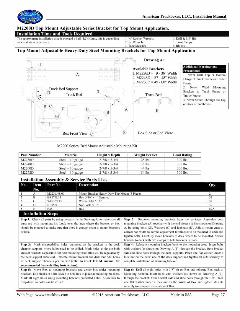
M2200D Top Mount Adjustable Series Bracket for Top Mount Application.
Installation Time and Tools Required The approximate installation time is one and a half (1.5) Hours; this is depending
on installation experience.
1. ½” Ratchet Wrench.
2. ½” Wrench 3. Tape Measure
4. Drill & 3/8” Bit
5. Two Clamps 6. Blocks
Top Mount Adjustable Heavy Duty Steel Mounting Brackets for Top Mount Application
E
A
Box Front View Box Side or End View
2
1
Truck Bed Truck Bed
Truck Bed Support
M2200 Series, Bed Mount Adjustable Mounting Kit
BDB
C
1
3
B CD
A
Available Brackets
1. M2236D = 9 - 36" Width2. M2248D = 37 - 48" Width3. M2260D = 49 - 60" Width
D
Part Number Material Height x Depth Weight Per Set Load Rating
M2236D Steel – 10 gauge 2-7/8 x 5-3/4 28 lbs. 300 lbs.
M2248D Steel – 10 gauge 2-7/8 x 5-3/4 36 lbs. 300 lbs.
M2260D Steel – 10 gauge 2-7/8 x 5-3/4 44 lbs. 300 lbs.
M2272D Steel – 10 gauge 2-7/8 x 5-3/4 54 lbs. 300 lbs.
Installation Assembly & Service Parts List. No. Item
No.
Part No. Description Qty.
1 A M2236/48/60 Mount Bracket Heavy Duty Top Mount (3 Piece) 2
2 B BR577L13 Bolt 5/16” x 1” Serrated 32
3 C WF267L13 Washer Flat 5/16” 32
4 D NL858L Nut Lock 5/16” 32
5 E Box Box N/A
Installation Steps
Step 1: Check all parts by using the parts list in Drawing A, to make sure all
parts are with mounting kit. Look over the area where the bracket or box
should be mounted to make sure that there is enough room to mount brackets
or box.
Step 2: Remove mounting brackets from the package. Assemble both
mounting brackets (A) together with the end pieces (1) like shown on Drawing
A, by using bolts (G), Washers (C) and locknuts (D). Adjust mount ends to
correct box width to correct adjustment for bracket to be mounted to deck and
tighten bolts. Carefully move brackets to deck where to be mounted. Secure
brackets to deck with two clamps to hold brackets in place.
Step 3: Mark the predrilled holes, patterned on the brackets to the deck
channel supports where holes need to be drilled. Mark holes as far too both
ends of brackets as possible, for best mounting result (this will be regulated by
the deck support channels). Relocate mount brackets and drill four 3/8” holes
in deck support channels per bracket (refer to truck O.E.M. manual for
recommended frame drilling instructions).
Step 4: Relocate mounting brackets back to the mounting area. Insert bolts
with washers (as shown on Drawing A (1)) through the bracket, from bracket
side and slide bolts through the deck supports. Place one flat washer under a
lock nut on the back side of the deck support and tighten all nuts securely to
complete installation of mounting bracket.
Step 5: Move Box to mounting brackets and center box under mounting
brackets. Use blocks or a lift device to hold box in place at mounting brackets.
Mark all eight holes using mounting brackets predrilled holes. Allow box to
drop down so holes can be drilled.
Step 6: Drill all eight holes with 3/8” bit on Box and relocate Box back to
Mounting position. Insert bolts with washers (as shown on Drawing A (2))
through the bracket, from bracket side and slide bolts through the Box. Place
one flat washer under a lock nut on the inside of Box and tighten all nuts
securely to complete installation of Box.
Drawing A:
Additional Warnings and
Precautions!
1. Never Drill Top or Bottom
Flange of Truck Frame or Trailer
Frame.
2. Never Weld Mounting
Brackets to Truck Frame or
Trailer Frame.
3. Never Mount Through the Top
or Back of Toolboxes.

American Truckboxes, LLC., Installation Manual
Web Page: www.truckbox.com 2018 American Truckboxes, LLC. Made in USA Page 28
Bumper BLB Series - Installation Mounting Instructions.
Diagram A:
SSBLB4L Installation Assembly Parts List No. Item
No.
Part No. Description Qty.
1 A SBLB Bumper N/A
2 B BH858R17 ½” x 2” Hex Bolt (Grade 8) 4
3 C WF858R ½” Lock Washer (Grade 8) 4
4 D NL858R ½” Nylon Lock Nut (Grade 8) 8
5 E SSLB-AS-14 ¼” Aluminum Spacers 4
Reflector or Reflection decals and License Plate Holder are optional.
Installation Steps Step 1: Check all parts by using the installation assembly parts list in
this manual, and make sure all parts are with package. Look over the
area where the Bumper should be mounted to make sure that there is
enough room to mount box.
Step 2: Remove all components from package and carefully move
Bumper to the frame where to be mounted, to assure Bumper is
mountable at that area. Holes are predrilled on Bumper for easy
mounting, but hole pattern may vary on truck.
Step 3: If hole pattern does not match, mark the predrilled holes
patterned, on the Truck Frame where holes need to be drilled. Remove
Bumper and drill four 1/2” diameter holes at each mark on the frame
(refer to truck O.E.M. shop manual for recommended frame
drilling instructions).
Step 6: Relocate Bumper to the frame. Insert Bolts with washers,
through the holes (as shown on Drawing A). Add spacers and place
one flat washer under a lock nut and tighten all nuts securely to
complete installation.
Note: Check and tighten bolts periodically. Note. If spacing is required due to truck frame design, place an aluminum spacer between bumper mount and truck frame as shown on diagram above.
Bumper Wiring Diagram Instructions.
Maintaining &
Caring for Your
Box.
Check and tighten
bolts periodically.
Additional Warnings and Precautions!
1. Never Drill Top or Bottom Flange of
Truck Frame or Trailer Frame.
2. Never Weld Mounting Brackets to
Truck Frame or Trailer Frame.
3. Never Mount Through the Top or Back
of Toolboxes.
American Truckboxes, LLC., Installation Manual
Web Page: www.truckbox.com 2018 American Truckboxes, LLC. Made in USA Page 29
Special Notice
This manual contains drawings and written material, which are for the sole purpose of mounting and providing guidelines for
installing our boxes and/or equipment in various configurations. Keep in mind that these are only intended as guidelines and not to
be construed as construction drawings or specifications.
America Truckboxes, LLC shall not be responsible in any way for anything other than the providing of equipment and materials
ordered. Guidelines shown in this manual may not meet or be in accordance with local, state, or federal regulations in effect at time
of installation.
American Truckboxes, LLC has the right to make changes in design at any time without notice.
Office Hours
Monday through Friday - 8:00am to 11:45am and 1:00pm to 5:00pm
American Truckboxes, LLC. 15750 6th Street SE, Blanchard, ND 58009
Phone: (888) 996-0376
Email: [email protected]
AMERICAN TRUCKBOXES, LLC. - LIMITED WARRANTY
This LIMITED WARRANTY is made by American Truckboxes, LLC, 15750 6th Street SE, Blanchard, North Dakota 58009 to the original retail
purchaser of American Truckboxes, LLC products. If you have any questions or need assistance regarding this warranty and the warranty of your
product, please call our customer service department at: (888) 996-0376, between the hours 8:00AM to 5:00PM CST. This warranty applies to
all product purchased on or after January 1, 2018.
AMERICAN TRUCKBOXES, LLC WARRANTS THAT THIS PRODUCT WILL BE FREE FROM DEFECTS IN MATERIAL AND
WORKMANSHIP FOR A PERIOD OF SIXTY (60) MONTHS ON STANDARD BOXES, TWELVE (12) MONTHS ON CUSTOM BOXES
(MODIFIED OR SPECIAL DESIGN TO CUSTOMER SPECIFICATIONS) AND TWELVE (12) MONTHS ON AUXILIARY TANKS,
FROM DATE OF PURCHASE BY THE ORIGINAL RETAIL PURCHASER ONLY. THIS WARRANTY TERMINATES IF THE
ORIGINAL PURCHASER TRANSFERS THE AMERICAN TRUCKBOXES, LLC PRODUCT TO ANY OTHER PERSON.
If purchaser discovers that the product fails to fulfill the warranty before the warranty period, original purchaser must promptly contact
American Truckboxes, LLC in writing of the nonconformity, to make arrangement for an inspection of this product. A copy of the original sales
receipt must be supplied to the manufacturer at the time a warranty claim is made. If American Truckboxes, LLC determines a defect exists,
American Truckboxes, LLC shall, at its option and expense, repair or replace any defective parts. All warranty repairs shall be made by an
authorized American Truckboxes, LLC product dealer or American Truckboxes LLC approved service man. Any part or parts of the goods not
manufactured by American Truckboxes LLC are not warranted for any purpose.
This warranty shall not apply or expressly exclude, if the American Truckboxes, LLC product has been subject to an accident, normal wear and
tear, cosmetic rust, scratches, unlawful vehicle operation, act of God, improper maintenance, misuse or alteration made by anyone other than
American Truckboxes, LLC or a product dealer of American Truckboxes, LLC approved service personal or company. Defects resulting from
conditions beyond the manufacturer control, but not limited to, overloading, misuse or failure to assemble or mount the product according to the
manufacturer’s installation guide line, written instructions or damage to the contents of the box or vehicle.
Purchaser must deliver written notice of any claimed defect or failure covered by this Limited Warranty within thirty (30) days after
discovery. Such notice must specify the date of purchase as well as the nature of the defect or failure.
THE WARRANTY PRINTED ABOVE IS THE ONLY WARRANTY TO THIS PURCHASE. ALL OTHER WARRANTIES, EXPRESS OR
IMPLIED, INCLUDING BUT NOT LIMITED TO THE IMPLIED WARRANTIES OF MERCHANTABILITY AND FITNESS FOR A
PARTICULAR PURPOSE ARE HEREBY DISCLAIMED.