installation built-in side-by-side refrigerators instructions
TRANSCRIPT

Installation
Instructions
Built-In Side-By-SideRefrigerators
If you have questions, call 1-877-4ELECTROLUX 877-435-3287 or visit our website at:
BEFORE YOU BEGINRead these instructions completelyand carefully.
• IMPORTANT — Observe all governing codes and ordinances.
• Note to Installer – Be sure to leave theseinstructions for the consumer’s and localinspector’s use.
• Note to Consumer – Keep these instructionswith your Owner’s Manual for future reference.
• Skill Level – Installation of this refrigeratorrequires basic mechanical, carpentry andplumbing skills. Proper installation is theresponsibility of the installer. Product failuredue to improper installation is not coveredunder the Electrolux Home ProductsWarranty. See warranty information.
• Completion Time – 90 minutes (newinstallations require more time thanreplacement installations).
CAUTION:Due to the weight and size of this refrigerator,and to reduce the risk of personal injury ordamage to the product, A MINIMUM OF 4PEOPLE ARE REQUIRED TO BRING THE UNITINTO THE HOME AND 2 PEOPLE AREREQUIRED FOR PROPER INSTALLATION.
WARNING:• These refrigerators are top-heavy and must
be secured to prevent the possibility oftipping forward. Anti-Tip protection isrequired. See Step 4 on page 30 for details.
• Use this appliance only for its intended purpose.• Immediately repair or replace electric power
supply cords that become frayed or damaged.• Set the Master Power switch to the
O (OFF) position before cleaning or makingrepairs.
• Repairs should be made by a qualifiedservice technician.
For local service in your area, call1-877-4ELECTROLUX or 877-435-3287
For parts and accessories, call 1-877-4ELECTROLUX or 877-435-3287
READ CAREFULLY.KEEP THESE INSTRUCTIONS.
15
Installation Instructions
16
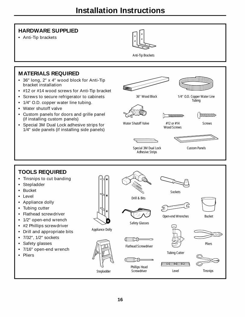
HARDWARE SUPPLIED• Anti-Tip brackets
Anti-Tip Brackets
MATERIALS REQUIRED• 36″ long, 2″ x 4″ wood block for Anti-Tip
bracket installation• #12 or #14 wood screws for Anti-Tip bracket• Screws to secure refrigerator to cabinets• 1/4″ O.D. copper water line tubing.• Water shutoff valve• Custom panels for doors and grille panel
(if installing custom panels)• Special 3M Dual Lock adhesive strips for
1/4″ side panels (if installing side panels)
36″ Wood Block 1/4″ O.D. Copper Water LineTubing
TOOLS REQUIRED• Tinsnips to cut banding• Stepladder• Bucket• Level• Appliance dolly• Tubing cutter• Flathead screwdriver• 1/2″ open-end wrench• #2 Phillips screwdriver• Drill and appropriate bits• 7/32″, 1/2″ sockets• Safety glasses• 7/16″ open-end wrench• Pliers
Appliance Dolly
Stepladder
Safety Glasses
Water Shutoff Valve #12 or #14 Wood Screws
Screws
Special 3M Dual Lock Adhesive Strips
Custom Panels
Sockets
Open-end Wrenches Bucket
Drill & Bits
Flathead Screwdriver
Tubing Cutter
Phillips HeadScrewdriver Level
Pliers
Tinsnips
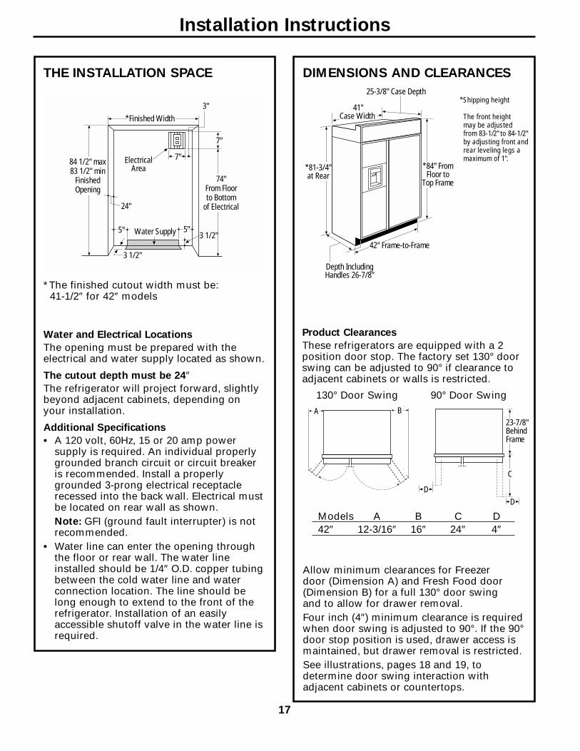
THE INSTALLATION SPACE
Water and Electrical Locations
The opening must be prepared with theelectrical and water supply located as shown.
The cutout depth must be 24″The refrigerator will project forward, slightlybeyond adjacent cabinets, depending onyour installation.
Additional Specifications
• A 120 volt, 60Hz, 15 or 20 amp powersupply is required. An individual properlygrounded branch circuit or circuit breakeris recommended. Install a properlygrounded 3-prong electrical receptaclerecessed into the back wall. Electrical mustbe located on rear wall as shown.Note: GFI (ground fault interrupter) is notrecommended.
• Water line can enter the opening throughthe floor or rear wall. The water lineinstalled should be 1/4″ O.D. copper tubingbetween the cold water line and waterconnection location. The line should belong enough to extend to the front of therefrigerator. Installation of an easilyaccessible shutoff valve in the water line isrequired.
DIMENSIONS AND CLEARANCES
Allow minimum clearances for Freezer door (Dimension A) and Fresh Food door(Dimension B) for a full 130° door swing and to allow for drawer removal.Four inch (4″) minimum clearance is requiredwhen door swing is adjusted to 90°. If the 90°door stop position is used, drawer access ismaintained, but drawer removal is restricted.See illustrations, pages 18 and 19, todetermine door swing interaction withadjacent cabinets or countertops.
*The finished cutout width must be:41-1/2″ for 42″ models
42" Frame-to-Frame
Depth IncludingHandles 26-7/8"
41" Case Width
25-3/8" Case Depth
*81-3/4"at Rear
*84" FromFloor to
Top Frame
*Finished Width
ElectricalArea
84 1/2" max83 1/2" min
FinishedOpening
74"From Floorto Bottom
of Electrical24"
5" 5"3 1/2"Water Supply
3 1/2"
3"
7"
7"
Product Clearances
These refrigerators are equipped with a 2position door stop. The factory set 130° doorswing can be adjusted to 90° if clearance toadjacent cabinets or walls is restricted.
130° Door Swing 90° Door SwingBA
23-7/8"BehindFrame
C
DD
Models A B C D42″ 12-3/16″ 16″ 24″ 4″
Installation Instructions
*Shipping height
The front height may be adjusted from 83-1/2" to 84-1/2"by adjusting front andrear leveling legs amaximum of 1".
17
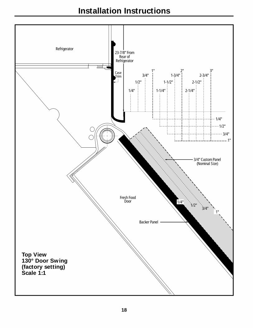
1/2"
1"
3/4" Custom Panel(Nominal Size)
1/4"
1/2"
3/4"2"
1-1/4"
1-1/2"
1-3/4"3"
2-1/4"
2-1/2"
2-3/4"
1/4"
1/2"
3/4"
Fresh FoodDoor
Backer Panel
23-7/8" FromRear of
Refrigerator
1"
Refrigerator
CaseTrim
3/4"
1/4"
1"
Top View130° Door Swing(factory setting)Scale 1:1
Installation Instructions
18
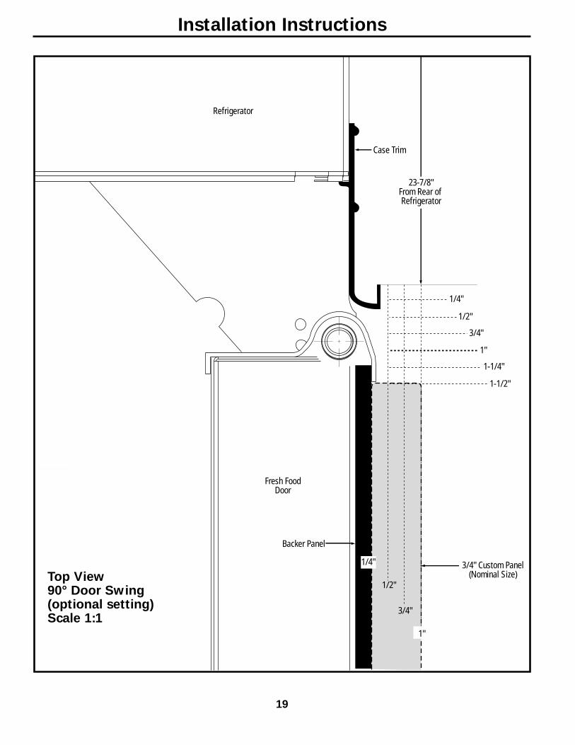
1/2"
1/4"
1/2"
3/4"
1"
1-1/4"
1-1/2"
23-7/8"From Rear of Refrigerator
3/4" Custom Panel(Nominal Size)
Case Trim
Refrigerator
Fresh FoodDoor
Backer Panel
3/4"
1/4"
1"
Top View90° Door Swing(optional setting)Scale 1:1
Installation Instructions
19
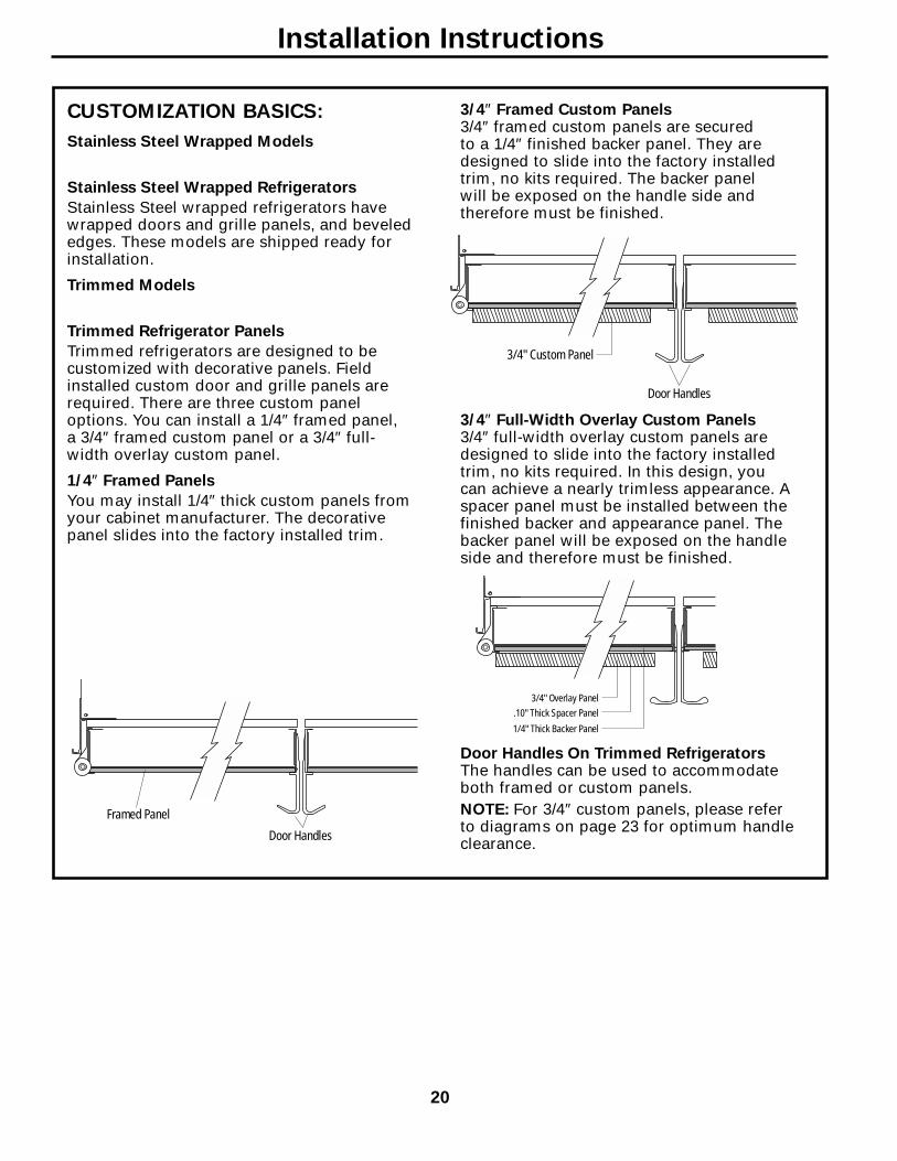
CUSTOMIZATION BASICS:
Stainless Steel Wrapped Models
Stainless Steel Wrapped Refrigerators
Stainless Steel wrapped refrigerators havewrapped doors and grille panels, and bevelededges. These models are shipped ready forinstallation.
Trimmed Models
Trimmed Refrigerator Panels
Trimmed refrigerators are designed to becustomized with decorative panels. Fieldinstalled custom door and grille panels arerequired. There are three custom paneloptions. You can install a 1/4″ framed panel, a 3/4″ framed custom panel or a 3/4″ full-width overlay custom panel.
1/4″ Framed Panels
You may install 1/4″ thick custom panels fromyour cabinet manufacturer. The decorativepanel slides into the factory installed trim.
Door Handles On Trimmed RefrigeratorsThe handles can be used to accommodateboth framed or custom panels.NOTE: For 3/4″ custom panels, please refer to diagrams on page 23 for optimum handleclearance.
3/4″ Framed Custom Panels3/4″ framed custom panels are secured to a 1/4″ finished backer panel. They aredesigned to slide into the factory installedtrim, no kits required. The backer panel will be exposed on the handle side andtherefore must be finished.
3/4″ Full-Width Overlay Custom Panels3/4″ full-width overlay custom panels aredesigned to slide into the factory installedtrim, no kits required. In this design, youcan achieve a nearly trimless appearance. Aspacer panel must be installed between thefinished backer and appearance panel. Thebacker panel will be exposed on the handleside and therefore must be finished.
Door Handles
3/4" Custom Panel
3/4" Overlay Panel.10" Thick Spacer Panel
1/4" Thick Backer Panel
Framed Panel
Door Handles
Installation Instructions
20

1/4″ FRAMED PANEL DIMENSIONSIf you choose to install framed panels, theymust be cut to the dimensions shown. Thepanels will slide into the frame on the doorand grille.
IMPORTANT NOTE: Maximum weight for Fresh Food panel is 70 pounds and 30 pounds total for Freezer panels.
IMPORTANT NOTE: Dispenser Trim
The refrigerator is supplied with factory installeddispenser trim.• If panel is less than 1/4″ thick, a noticeable gap will be
created around the dispenser trim. Foam tape may beapplied on the door to improve the fit.
• If panel is more than 1/4″ thick, the panel will not fitbehind the trim.
ED
F
A
BGrille Panel
C
DispenserCutout
FreezerPanel
Fresh Food Panel
G
1/4"Panel
Door
5/16"Trim
Reveal
Front Panel Dimensions (in inches)
A B C D E F G
42″ Models 39-15/16 10-3/4 67-7/8 16-7/16 22-11/32 17-13/16 35-5/32
Installation Instructions
21

3/4″ FRAMED CUSTOM PANEL OPTIONFor a more custom appearance, 3/4″ framed custompanels may be installed on trimmed models. The overlaypanel is secured to a 1/4″ finished backer panel. Theassembled custom panel then slides into the trim withthe same procedure described on page 33.
3/4″ FULL-WIDTH OVERLAY CUSTOM PANEL OPTIONThis design provides a nearly trimless appearance. The fullwidth overlay panel covers most of the door trim. In this design,a spacer panel must be installed between the finished backerand overlay panel.
NOTE: Left-to-right offset is not equalto top-to-bottom offset.
NOTE: Left-to-right offset is not equalto top-to-bottom offset.
.250 + .750 = 1.000 Maximum Total Panel Thickness
IMPORTANT NOTE: Maximum total weight for anyassembled Fresh Food panel is 70 pounds and 30 pounds total for Freezer panels.
3/4"CustomOverlay Panel
1/4"BackerPanel
Door
3/4"
Overlay Panel
Backer Panel
Custom OverlayPanel
1/4"BackerPanel
Door
.10 InchSpacer
Installation Instructions
22
.250 + .10 + .750 = 1.100 Maximum Total Panel Thickness
Spacer Panel
Overlay Panel
Backer Panel

3/8"
3-1/8"
5/16"
1" Thick Max.or 3/4" Plus1/4" Backer
B
2-1/2"
3-1/8" Min.1/4" Max.
A
5/16"
Required for OptimalHandle Clearance
3/4″ FRAMED CUSTOM WOOD PANELSSecured to a 1/4″ finished backer panel. This designprovides a framed appearance.
Fresh Food Panel
Installation Instructions
23
42″ Models A B
1/4″ Backer Panel 22-5/16″ 67-7/8″3/4″ Overlay Panel 18-13/16″ 67-1/4″

2-1/2"
3-1/8" Min.1/4" Max.
Required for OptimalHandle Clearance
3/8"
3-1/8"1" Thick Max.or 3/4" Plus1/4" Backer
5/16"
A
5/16"B
3/8"
1" Thick Max.or 3/4" Plus1/4" Backer
5/16"
5/16"
3-1/8"
A
B
1" Thick Max.or 3/4" Plus1/4" Backer
5/16"
5/16"
1/4"
1/4"
A
B
3/4″ FRAMED CUSTOM WOOD PANELSSecured to a 1/4″ finished backer panel. This design provides a framed appearance.
Grille Panel
Upper Freezer Panel
Lower Freezer Panel
Installation Instructions
24
42″ Models A B
1/4″ Backer Panel 39-15/16″ 10-3/4″3/4″ Overlay Panel 39-7/16″ 10-1/8″
42″ Models A B
1/4″ Backer Panel 16-7/16″ 17-13/16″3/4″ Overlay Panel 12-15/16″ 17-3/16″
42″ Models A B
1/4″ Backer Panel 16-7/16″ 35-1/8″3/4″ Overlay Panel 12-15/16″ 34-1/2″
1/4"Max.
Required for OptimalHandle Clearance
3-1/8"
2-1/2"
3-1/8" Min.
B
A
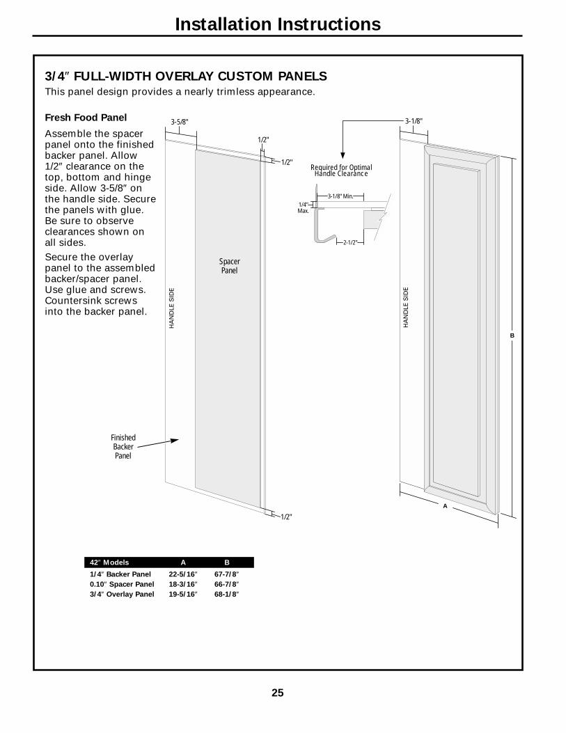
3/4″ FULL-WIDTH OVERLAY CUSTOM PANELSThis panel design provides a nearly trimless appearance.
Assemble the spacerpanel onto the finishedbacker panel. Allow1/2″ clearance on thetop, bottom and hingeside. Allow 3-5/8″ onthe handle side. Securethe panels with glue.Be sure to observeclearances shown onall sides.Secure the overlaypanel to the assembledbacker/spacer panel.Use glue and screws.Countersink screwsinto the backer panel.
Installation Instructions
25
42″ Models A B
1/4″ Backer Panel 22-5/16″ 67-7/8″0.10″ Spacer Panel 18-3/16″ 66-7/8″3/4″ Overlay Panel 19-5/16″ 68-1/8″
3-5/8"
1/2"
1/2"
1/2"
Fresh Food Panel
Spacer Panel
Finished Backer Panel
3-1/8" Min.1/4" Max.
Required for OptimalHandle Clearance
3-1/8"
3-1/8"5/16"
5/16"
A
B
A
B
A
B
2-1/2"
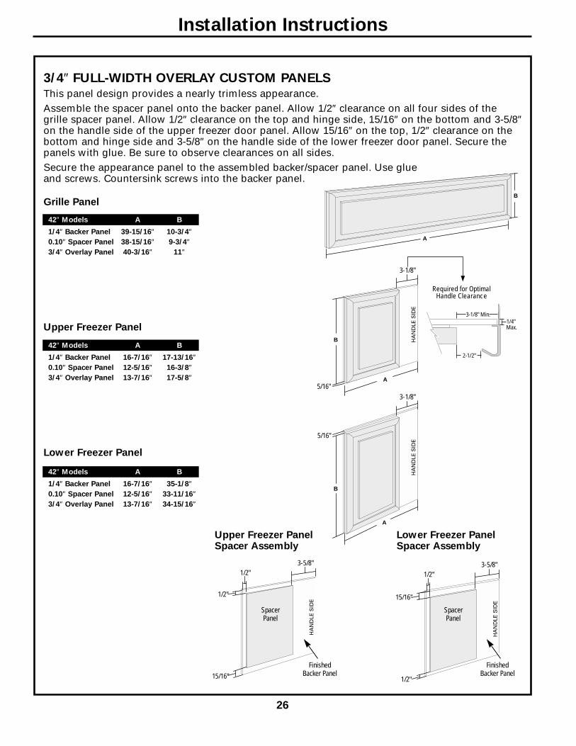
3/4″ FULL-WIDTH OVERLAY CUSTOM PANELSThis panel design provides a nearly trimless appearance.Assemble the spacer panel onto the backer panel. Allow 1/2″ clearance on all four sides of thegrille spacer panel. Allow 1/2″ clearance on the top and hinge side, 15/16″ on the bottom and 3-5/8″on the handle side of the upper freezer door panel. Allow 15/16″ on the top, 1/2″ clearance on thebottom and hinge side and 3-5/8″ on the handle side of the lower freezer door panel. Secure thepanels with glue. Be sure to observe clearances on all sides.Secure the appearance panel to the assembled backer/spacer panel. Use glue and screws. Countersink screws into the backer panel.
Grille Panel
Lower Freezer Panel
Upper Freezer Panel
Installation Instructions
26
42″ Models A B
1/4″ Backer Panel 39-15/16″ 10-3/4″0.10″ Spacer Panel 38-15/16″ 9-3/4″3/4″ Overlay Panel 40-3/16″ 11″
42″ Models A B
1/4″ Backer Panel 16-7/16″ 35-1/8″0.10″ Spacer Panel 12-5/16″ 33-11/16″3/4″ Overlay Panel 13-7/16″ 34-15/16″
42″ Models A B
1/4″ Backer Panel 16-7/16″ 17-13/16″0.10″ Spacer Panel 12-5/16″ 16-3/8″3/4″ Overlay Panel 13-7/16″ 17-5/8″
3-5/8"
15/16"
1/2"
1/2"
Spacer Panel
Finished Backer Panel
3-5/8"
1/2"
15/16"
1/2"
Spacer Panel
Finished Backer Panel
Upper Freezer PanelSpacer Assembly
Lower Freezer PanelSpacer Assembly
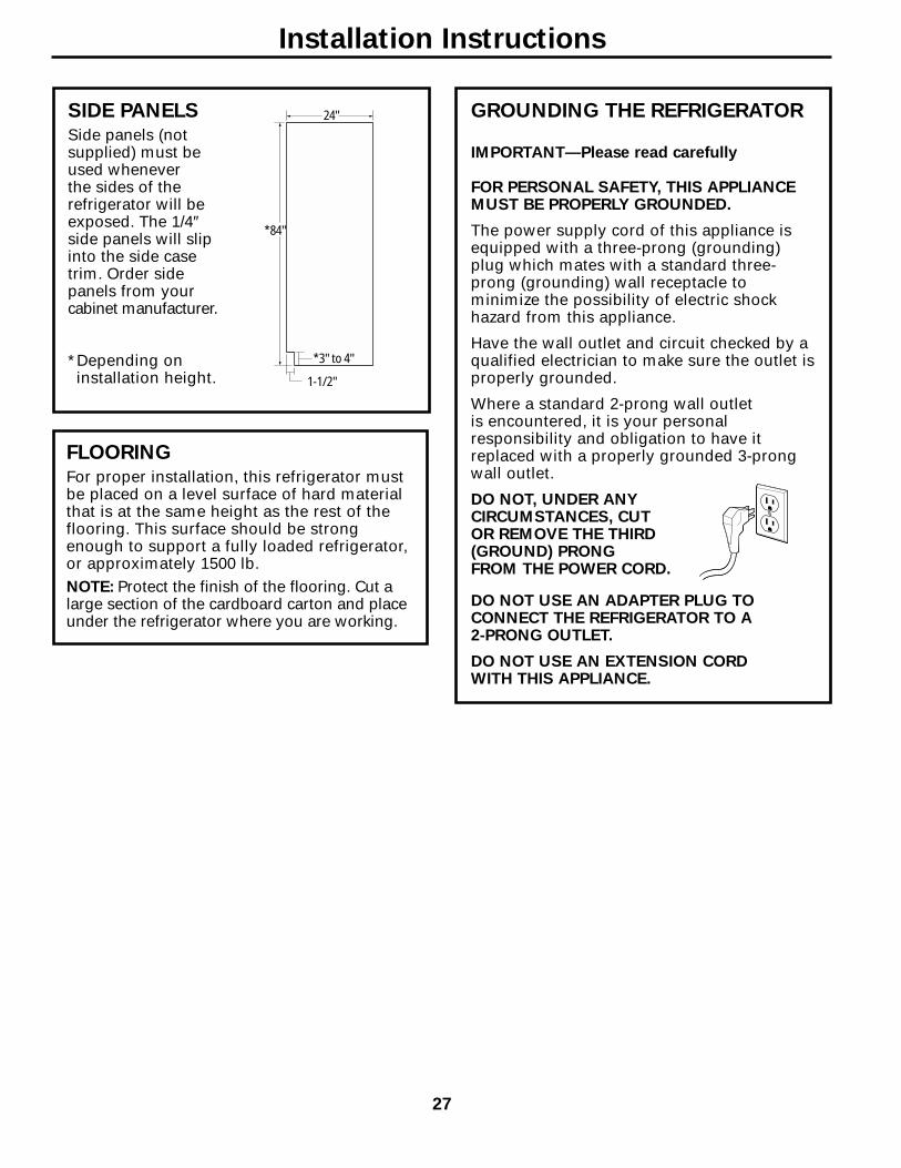
GROUNDING THE REFRIGERATOR
IMPORTANT—Please read carefully
FOR PERSONAL SAFETY, THIS APPLIANCEMUST BE PROPERLY GROUNDED.
The power supply cord of this appliance isequipped with a three-prong (grounding)plug which mates with a standard three-prong (grounding) wall receptacle tominimize the possibility of electric shockhazard from this appliance.
Have the wall outlet and circuit checked by aqualified electrician to make sure the outlet isproperly grounded.
Where a standard 2-prong wall outlet is encountered, it is your personalresponsibility and obligation to have itreplaced with a properly grounded 3-prongwall outlet.
DO NOT, UNDER ANYCIRCUMSTANCES, CUT OR REMOVE THE THIRD (GROUND) PRONGFROM THE POWER CORD.
DO NOT USE AN ADAPTER PLUG TOCONNECT THE REFRIGERATOR TO A 2-PRONG OUTLET.
DO NOT USE AN EXTENSION CORD WITH THIS APPLIANCE.
SIDE PANELSSide panels (not supplied) must beused whenever the sides of therefrigerator will beexposed. The 1/4″side panels will slipinto the side casetrim. Order sidepanels from yourcabinet manufacturer.
*Depending oninstallation height.
FLOORINGFor proper installation, this refrigerator mustbe placed on a level surface of hard materialthat is at the same height as the rest of theflooring. This surface should be strongenough to support a fully loaded refrigerator,or approximately 1500 lb.NOTE: Protect the finish of the flooring. Cut alarge section of the cardboard carton and placeunder the refrigerator where you are working.
24"
*84"
*3" to 4"
1-1/2"
Installation Instructions
27

1 REMOVE PACKAGING
CAUTION: Refrigerator is Top-Heavy—be careful when moving. When using an appliance dolly, handle from Freezer side only.• Carefully cut banding at the top and
bottom; remove outer carton.• Slide out rear corner posts (2).• Slide carton off top of cabinet.
NOTE: DO NOT LAY CABINET DOWN IN ORDER TO REMOVE SKID!
• The unit is secured to the skid with six 7/16″ bolts and six 1/2″ nuts.
• Remove all six 7/16″ bolts that securemetal brackets to the refrigerator.
• Remove the three 1/2″ nuts and washersfrom the Freezer side.
• Remove nut from rear wood block on Freezer side.
• Tilt unit up on Freezer side toward FreshFood side.
• Push bolts down, remove metal bracketfrom Freezer side. Remove wood blockfrom Freezer side.
• Slide the appliance dolly underneath theFreezer side.
• Using corner posts (2 on front corners) to prevent damage, secure unit toappliance dolly.
NOTE: If corner posts are too long, cut theposts to a shorter length.
• Lift the unit off the skid with the appliancedolly.
• Remove toekick taped to the top of theunit.
• Set toekick aside for final installation.
CAUTION: DO NOT ATTEMPTTO ROLL OR DRAG UNTIL UNIT IS OFF SKID.
CAUTION: MAKE SURE THE WATER LINE IS CLEAR OF APPLIANCE DOLLY TO AVOID DAMAGE.
MetalBracket
1/2" Nuts
Bolts
Toekick Taped toTop of Unit
Installation Instructions
28

2 INSTALL WATER LINE• A cold water supply is required for
automatic icemaker operation. The waterpressure must be between 40 and 120 psi.
• Route 1/4″ O.D. copper tubing betweencold water line and the water connectionlocation.
• Tubing should be long enough to extendto the front of the refrigerator. Allowenough tubing to accommodate bendleading into the water line connection.
NOTE: Certain types of plastic may crack orrupture with age and cause water damage toyour home.Shut off the main water supply.
Turn on the nearest faucet long enough to purge all the water from the line.• Install a shutoff valve between the
icemaker water valve and cold water pipein a basement or cabinet. The shutoffvalve should be located where it will beeasily accessible.
NOTE: It is best to install the valve into avertical water pipe. If you install the valve intoa horizontal water pipe, make the connectionat the top or side to avoid drawing off anysediment from the water pipe.• Drill a 1/4″ hole in the water pipe.• Fasten the shutoff valve to the pipe with
pipe clamp.• Tighten the clamp screws until the
sealing washer begins to swell. Do notOVERTIGHTEN.
• Place a compression nut and ferrule(sleeve) for copper tubing onto the end of the tubing and connect it to the shutoffvalve. Make sure the tubing is fully insertedinto the valve and ferrule is tightened.
• Turn on the main water supply and flush debris. Run about a quart of waterthrough the tubing into a bucket. Shut off water supply at the shutoff valve.
NOTE: Saddle type shutoff valves areincluded in many water supply kits. Beforepurchasing, make sure a saddle type valvecomplies with your local plumbing codes.
Floor
Copper Tubing
Saddle TypeShutoff Valve
Compression Nut
Ferrule(Sleeve)
Outlet Valve
Packing Nut
NOTE: Commonwealth of MassachusettsPlumbing Codes 248CMR must be adheredto. Saddle valves are illegal and use is notpermitted in Massachusetts. Consult withyour licensed plumber.
Installation Instructions
29
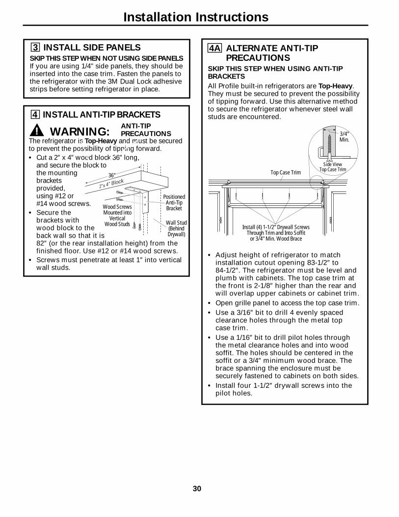
3 INSTALL SIDE PANELSSKIP THIS STEP WHEN NOT USING SIDE PANELSIf you are using 1/4" side panels, they should beinserted into the case trim. Fasten the panels tothe refrigerator with the 3M Dual Lock adhesivestrips before setting refrigerator in place.
4A ALTERNATE ANTI-TIPPRECAUTIONS
SKIP THIS STEP WHEN USING ANTI-TIPBRACKETS
All Profile built-in refrigerators are Top-Heavy. They must be secured to prevent the possibilityof tipping forward. Use this alternative methodto secure the refrigerator whenever steel wallstuds are encountered.
• Adjust height of refrigerator to matchinstallation cutout opening 83-1/2″ to 84-1/2″. The refrigerator must be level andplumb with cabinets. The top case trim atthe front is 2-1/8″ higher than the rear andwill overlap upper cabinets or cabinet trim.
• Open grille panel to access the top case trim.• Use a 3/16″ bit to drill 4 evenly spaced
clearance holes through the metal top case trim.
• Use a 1/16″ bit to drill pilot holes throughthe metal clearance holes and into woodsoffit. The holes should be centered in thesoffit or a 3/4″ minimum wood brace. Thebrace spanning the enclosure must besecurely fastened to cabinets on both sides.
• Install four 1-1/2″ drywall screws into thepilot holes.
4 INSTALL ANTI-TIP BRACKETS
WARNING: The refrigerator is Top-Heavy and must be securedto prevent the possibility of tipping forward.• Cut a 2″ x 4″ wood block 36″ long,
and secure the block tothe mountingbracketsprovided,using #12 or#14 wood screws.
• Secure thebrackets withwood block to theback wall so that it is82″ (or the rear installation height) from thefinished floor. Use #12 or #14 wood screws.
• Screws must penetrate at least 1″ into verticalwall studs.
Install (4) 1-1/2" Drywall ScrewsThrough Trim and Into Soffit
or 3/4" Min. Wood Brace
Top Case TrimSide View
Top Case Trim
3/4"Min.
ANTI-TIPPRECAUTIONS
PositionedAnti-TipBracket
Wall Stud(BehindDrywall)
Wood ScrewsMounted into
VerticalWood Studs
36"
Installation Instructions
30

7 LEVEL REFRIGERATOR
All models have 4-point leveling. The front andback are supported by leveling legs. Both areaccessible from the front of the refrigerator.• To level the back of the refrigerator, turn
the 1/2″ hex nut located above the frontwheels. Turn clockwise to raise orcounterclockwise to lower the refrigerator.
• For front leveling, use a 7/16″ open-endwrench.
• Adjust height of refrigerator to matchinstallation cutout opening 83-1/2″ to 84-1/2″. The refrigerator should be level and plumb with cabinets.
IMPORTANT NOTE: The refrigerator must be level. If it is not, the doors may not alignevenly at the top. See Step 16.
CAUTION:The rear leveling legs and front leveling legsare limited to a maximum height adjustmentof 1″. If the installation requires more than 84-1/2″ height, the installer should elevate therefrigerator on a sheet of plywood or runners.Cabinet trim could be added across the top of the opening to shorten the opening. If youattempt to raise the refrigerator more than 1″, you will damage the front and rearleveling legs.
5 CONNECT POWER• Connect refrigerator power cord plug to
a properly grounded receptacle. Set theMaster Power switch to the I (ON) position.
• Check to make sure power to refrigerator is on by opening refrigerator door to see ifinterior lights are on.
CAUTION:• After power has been established, turn the
Master Power switch to the O (OFF) position.
6 MOVE INTO INSTALLATION SPACE
• Slide the unit into the installation space.• Place excess slack in the power cord on top
of the refrigerator.• Use care to ensure the power cord is not
pinched behind the unit.
RaiseGrillePanel
MasterPower Switch
Hex Nut AdjustsRear Leveling Legs
Leveling Leg
Heightfrom
Floor toBottom
of WoodBlock82"
Installation Instructions
31
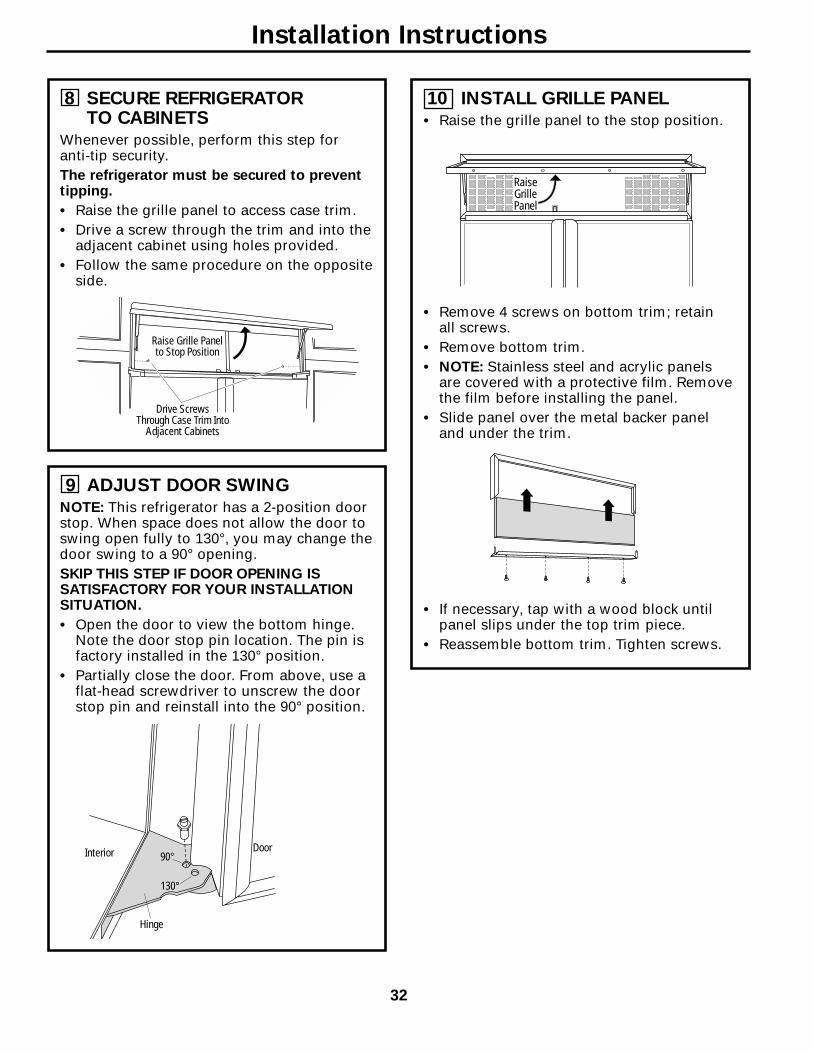
10 INSTALL GRILLE PANEL• Raise the grille panel to the stop position.
• Remove 4 screws on bottom trim; retain all screws.
• Remove bottom trim.• NOTE: Stainless steel and acrylic panels
are covered with a protective film. Removethe film before installing the panel.
• Slide panel over the metal backer paneland under the trim.
• If necessary, tap with a wood block untilpanel slips under the top trim piece.
• Reassemble bottom trim. Tighten screws.
RaiseGrillePanel
8 SECURE REFRIGERATOR TO CABINETS
Whenever possible, perform this step for anti-tip security. The refrigerator must be secured to preventtipping.
• Raise the grille panel to access case trim.• Drive a screw through the trim and into the
adjacent cabinet using holes provided.• Follow the same procedure on the opposite
side.
Drive ScrewsThrough Case Trim Into
Adjacent Cabinets
Raise Grille Panelto Stop Position
9 ADJUST DOOR SWINGNOTE: This refrigerator has a 2-position doorstop. When space does not allow the door toswing open fully to 130°, you may change thedoor swing to a 90° opening. SKIP THIS STEP IF DOOR OPENING ISSATISFACTORY FOR YOUR INSTALLATIONSITUATION.
• Open the door to view the bottom hinge.Note the door stop pin location. The pin isfactory installed in the 130° position.
• Partially close the door. From above, use aflat-head screwdriver to unscrew the doorstop pin and reinstall into the 90° position.
90°
130°
Hinge
DoorInterior
Installation Instructions
32
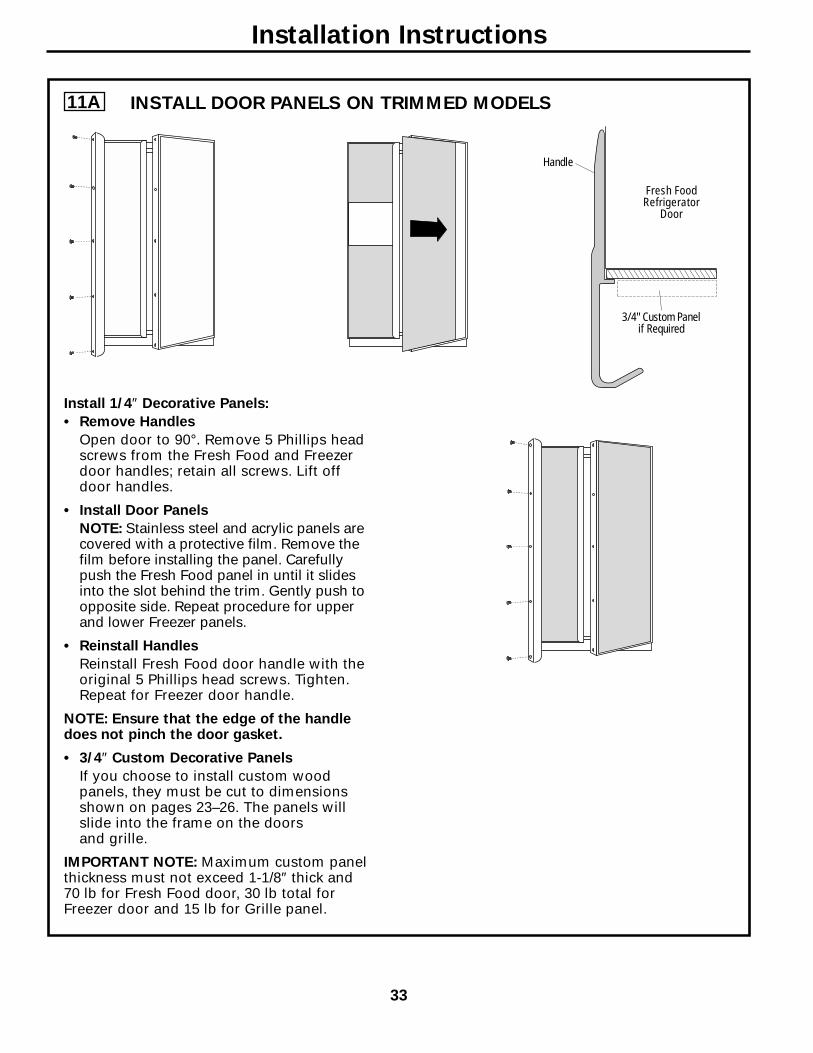
11A
Install 1/4″ Decorative Panels:
• Remove Handles
Open door to 90°. Remove 5 Phillips headscrews from the Fresh Food and Freezerdoor handles; retain all screws. Lift offdoor handles.
• Install Door Panels
NOTE: Stainless steel and acrylic panels arecovered with a protective film. Remove thefilm before installing the panel. Carefullypush the Fresh Food panel in until it slidesinto the slot behind the trim. Gently push toopposite side. Repeat procedure for upperand lower Freezer panels.
• Reinstall Handles
Reinstall Fresh Food door handle with theoriginal 5 Phillips head screws. Tighten.Repeat for Freezer door handle.
NOTE: Ensure that the edge of the handledoes not pinch the door gasket.
• 3/4″ Custom Decorative Panels
If you choose to install custom woodpanels, they must be cut to dimensionsshown on pages 23–26. The panels willslide into the frame on the doors and grille.
IMPORTANT NOTE: Maximum custom panelthickness must not exceed 1-1/8″ thick and70 lb for Fresh Food door, 30 lb total forFreezer door and 15 lb for Grille panel.
Fresh FoodRefrigerator
Door
Handle
3/4" Custom Panelif Required
Installation Instructions
33
INSTALL DOOR PANELS ON TRIMMED MODELS

11B
1. Remove handles from cartoning and any other protective packaging.
2. Place handle over pre-installed shoulder bolts (A) that are fastened into door in four locations.
3. While supporting handle and looking at upper end cap, fasten top-most allen set screw (B) with
supplied allen wrench, then fasten bottom allen set screw (C). See Figure 1.
4. Repeat Step 3 with bottom end cap using allen set screws (D and E), once upper section of handle is firmly secured to door. See Figure 2.
5. All set screws should be tightened and sub-flush (allen set screw should be buried just below the surface of the end cap) of handle end cap. The end caps should be drawn tight to freezer and refrigerator doors with no gaps.
Installation Instructions
34
INSTALL DOOR HANDLES ON STAINLESS STEEL MODELS
A A B
C
A A D
E
Figure 1Upper End Cap
Figure 2Bottom End Cap
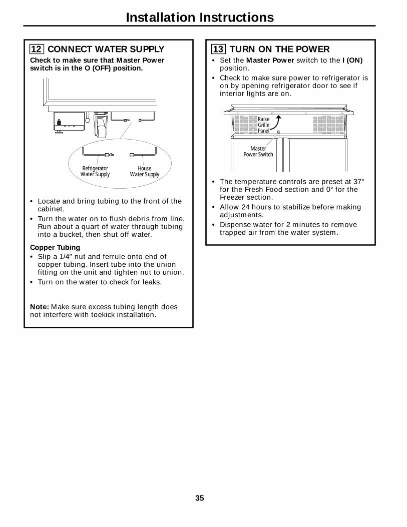
13 TURN ON THE POWER• Set the Master Power switch to the I (ON)
position.• Check to make sure power to refrigerator is
on by opening refrigerator door to see ifinterior lights are on.
• The temperature controls are preset at 37°for the Fresh Food section and 0° for theFreezer section.
• Allow 24 hours to stabilize before makingadjustments.
• Dispense water for 2 minutes to removetrapped air from the water system.
RaiseGrillePanel
MasterPower Switch
12 CONNECT WATER SUPPLYCheck to make sure that Master Powerswitch is in the O (OFF) position.
• Locate and bring tubing to the front of thecabinet.
• Turn the water on to flush debris from line.Run about a quart of water through tubinginto a bucket, then shut off water.
Copper Tubing
• Slip a 1/4″ nut and ferrule onto end ofcopper tubing. Insert tube into the unionfitting on the unit and tighten nut to union.
• Turn on the water to check for leaks.
Note: Make sure excess tubing length doesnot interfere with toekick installation.
RefrigeratorWater Supply
HouseWater Supply
Installation Instructions
35
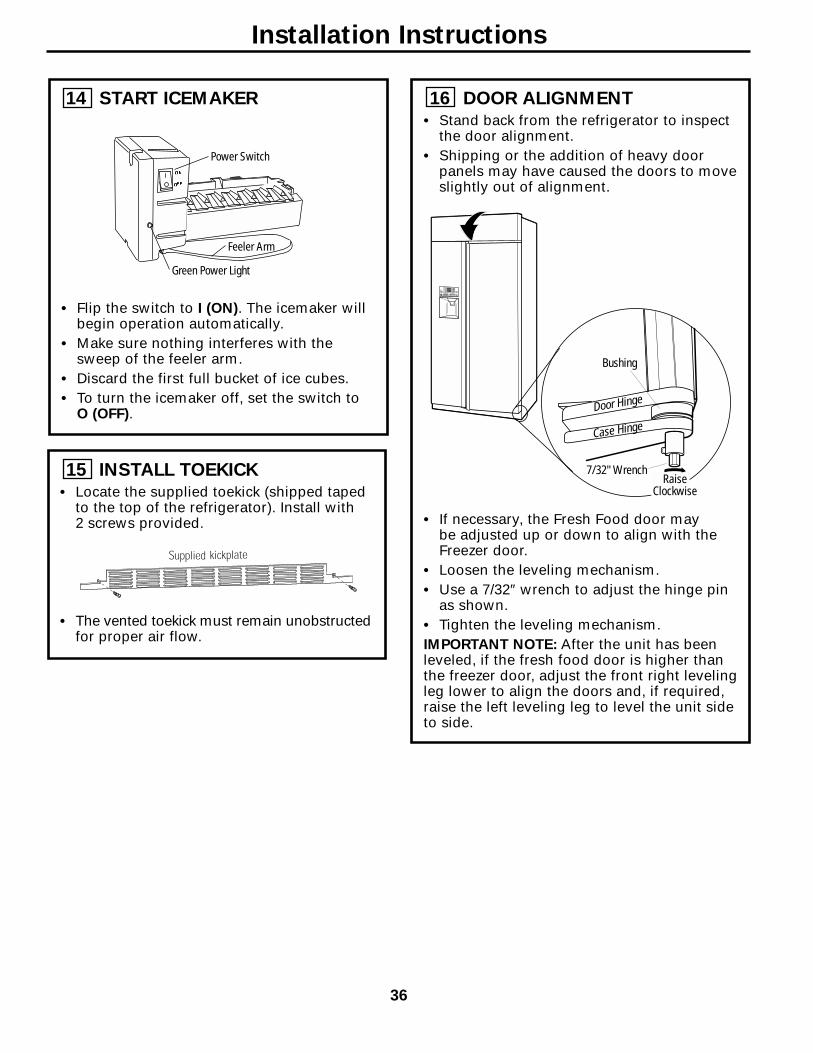
16 DOOR ALIGNMENT• Stand back from the refrigerator to inspect
the door alignment.• Shipping or the addition of heavy door
panels may have caused the doors to moveslightly out of alignment.
• If necessary, the Fresh Food door may be adjusted up or down to align with theFreezer door.
• Loosen the leveling mechanism.• Use a 7/32″ wrench to adjust the hinge pin
as shown.• Tighten the leveling mechanism.IMPORTANT NOTE: After the unit has beenleveled, if the fresh food door is higher thanthe freezer door, adjust the front right levelingleg lower to align the doors and, if required,raise the left leveling leg to level the unit sideto side.
14 START ICEMAKER
• Flip the switch to I (ON). The icemaker willbegin operation automatically.
• Make sure nothing interferes with thesweep of the feeler arm.
• Discard the first full bucket of ice cubes.• To turn the icemaker off, set the switch to
O (OFF).
15 INSTALL TOEKICK• Locate the supplied toekick (shipped taped
to the top of the refrigerator). Install with 2 screws provided.
• The vented toekick must remain unobstructedfor proper air flow.
Power Switch
Green Power Light
Feeler Arm
Bushing
Door Hinge
Case Hinge
7/32" WrenchRaise
Clockwise
Installation Instructions
36