installation and operator’s manual and operator’s manual ... switch positions: cold boiler...
TRANSCRIPT

INSTALLATION ANDOPERATOR’S MANUAL
WOOD GUN™ WOOD GASIFICATION BOILERModel: E155 SF
IMPORTANT: IN ORDER TO ACHIEVE SAFE AND SATISFACTORY RESULTS FROM YOUR ALTERNATE HEATING SYSTEMS BOILER, READSAFETY RULES AND INSTRUCTIONS CAREFULLY BEFORE INSTALLING AND OPERATING. ALL INSTALLATIONS MUST BE IN ACCORDANCE WITH STATE AND LOCAL CODES. SAVE THESE INSTRUCTIONS FOR FUTURE REFERENCE.
Your Alternate Heating Systems Boiler is capable of generating very hot temperatures. Boiler temperatures and flames in the ignition box area are capable of causing ignition or explosion of explosive or flammable products or explosion of the boiler itself if maximum safe water temperature is exceeded. Maximum safe water temperature is 200° Fahrenheit. Flammable or explosive products must never be stored in the same room or in the vicinity of a boiler, and the boiler water temperature must never be allowed to exceed 200° Fahrenheit.
ALTERNATE HEATING SYSTEMS2393 LITTLE EGYPT RDHARRISONVILLE, PA 17228717-987-0099WWW.WOODGUN.COM EMAIL:[email protected]
Record Model and Serial Number Below:
Model:Serial Number:Date of Purchase:


Copyright 2000 – 2015 Alternate Heating Systems.No portion of this publication may be reproduced without the
express written consent of Alternate Heating Systems.
Revision: 11/23/15

Table of ContentsIntroduction....................................................................................................................................................1
Explanation of Wood & Biomass Combustion............................................................................................1Wood Moisture Content & Wood Gasification...........................................................................................1Mode of Operation.....................................................................................................................................2
Boiler Installation...........................................................................................................................................5Boiler Location..........................................................................................................................................5
Boiler Room Requirements....................................................................................................................5Rigging and Positioning of Boiler..............................................................................................................6Clearances to Combustibles Required for Safety and Operation.................................................................6Boiler Assembly.........................................................................................................................................6
Cyclone Ash Collector...........................................................................................................................6Air Valve...............................................................................................................................................7Draft-Inducing Fan Assembly................................................................................................................7
Installation and maintenance of Electrical Controls and Gauges.................................................................7General Chimney Requirements.................................................................................................................8
Specific Chimney Requirements for the Wood Gun™...........................................................................8Flue pipe....................................................................................................................................................9Proper Chimney Connection......................................................................................................................9Boiler Piping for Hydronic Systems.........................................................................................................10
Piping the Boiler in Parallel with Another Boiler.................................................................................11Pressure Relief Valve...........................................................................................................................11Pressure Reducing Fill Valve...............................................................................................................11Expansion Tank Selection....................................................................................................................12Return Water Temperature...................................................................................................................12LOW WATER CUT OFF.....................................................................................................................12
Recommended Boiler Control Settings in Hydronic Systems...................................................................13Boiler Conditioner / Sealant.....................................................................................................................13Boiler Piping and Controls for Low Pressure Steam Systems...................................................................13Forced Hot Air Systems (Water to air Coil in Duct)..................................................................................14Domestic Hot Water Coil Piping..............................................................................................................14Oil Burner Assembly................................................................................................................................15
General Information............................................................................................................................15Models E180, and E250.......................................................................................................................15Oil/Gas Burner Combustion Chamber: Models E100 and E140...........................................................16Oil Burner Electrical Connection.........................................................................................................16Oil Burner Fuel Line Connection.........................................................................................................16Oil Burner Adjustment.........................................................................................................................16
Gas Burner Assembly...............................................................................................................................17Models E100 through E250.................................................................................................................17Gas Burner Adjustment........................................................................................................................18
Oil Automatic Switchover and Lockout Control.......................................................................................18Smoke flap...............................................................................................................................................18
Operating Information..................................................................................................................................20Starting a Fire: Switch Positions...............................................................................................................21
Switch Positions: Cold Boiler Startup..................................................................................................21Fuel Type.................................................................................................................................................21
The Wood Gun is designed to burn split or unsplit wood.....................................................................21Starting a Fire: Procedure.........................................................................................................................21
Charging the Boiler with Wood: Manual Feed.....................................................................................22

EPA Side Tunnel Refractory Plug........................................................................................................23Particle Fuel Delivery Option..............................................................................................................24
Adjustment of the Draft-Inducing Fan (Belt-Drive Only).........................................................................24Optional Automatic Fuel Delivery Systems..............................................................................................24
Burning Particle Wood with a Low Moisture Content..........................................................................25Use of Water Spray Kit........................................................................................................................25Option and Sequence of Events for Automatic Feed Systems..............................................................25Augers.................................................................................................................................................26Photo-Eye Fuel Level Sensing System.................................................................................................26
Wood Fuel Characteristics and Wood Storage..........................................................................................26Removal and Disposal of Ashes...............................................................................................................27Conditioning of Boiler Water...................................................................................................................27
pH...................................................................................................................................................27Dissolved Oxygen...........................................................................................................................28Solids..............................................................................................................................................28Alkalinity........................................................................................................................................28Phosphates......................................................................................................................................28Hardness.........................................................................................................................................28Oils.................................................................................................................................................29
Maintenance.................................................................................................................................................33Weekly Cleaning Procedure.....................................................................................................................33
Air Valve Cleaning and Maintenance...................................................................................................33Yearly Cleaning........................................................................................................................................34Air Valve Motor Replacement..................................................................................................................34
Removing Old Damper Motor.............................................................................................................34Installing the New Damper Motor.......................................................................................................34
Door Adjustment......................................................................................................................................35Load Door Seal Replacement...................................................................................................................36Front and Rear Inspection Door High Temperature Rope Installation.......................................................38Fan Assembly...........................................................................................................................................39Direct Drive Fan bearing replacement procedure......................................................................................40Refractory Replacement...........................................................................................................................43Center Brick.............................................................................................................................................43 Side brick Refractory Replacement.........................................................................................................45Fuel Diverter Blocks: auto Feed Only......................................................................................................46additional Information..............................................................................................................................46
Appendix A: Boiler Specification Diagram...................................................................................................47Additional Specifications.........................................................................................................................50
Pressure Drop......................................................................................................................................50Explanation of GPM Flow...................................................................................................................50Wood Gun E Series Specifications.......................................................................................................50
Appendix B: Wiring Diagrams......................................................................................................................52.....................................................................................................................................................................53Appendix C: Exploded Parts Drawings.........................................................................................................62Parts Listing..................................................................................................................................................64Appendix D: Troubleshooting Guide............................................................................................................68Appendix F: Boiler Piping and Ducting Examples........................................................................................72LIMITED WARRANTY...............................................................................................................................76

Introductione purpose of this manual is to assist you in the
installation, operation and maintenance of your new boiler in order to achieve the best performance possible.
We recommend that the unit be installed by a qualified installer who has a thorough knowledge of hydronic heating boiler systems and will comply with all of the requirements of the authority having jurisdiction over the installation. Should your installation be a steam boiler, it is even more important that experienced personnel be consulted to ensure that the necessary safety controls are installed and properly wired.
Read the entire instruction manual carefully and understand it thoroughly before installing or operating this unit. Save these instructions and review them periodically as an aid to maintaining your boiler and following safe operating practices.
All Alternate Heating Systems boilers can be supplied with the ASME “H” stamp and National Board number for an additional fee when requested prior to purchase. Alternate Heating Systems boilers are built to the most rigid quality control standard. You can be assured that you will receive the highest quality product.
EXPLANATION OF WOOD & BIOMASSCOMBUSTION
e burning of wood involves a series of very complex chemical reactions that are time and temperature dependent. e pieces of wood (or particles) may be thought of as containers that store combustible gases that are released when heat is applied. e various gases that emanate from heated wood have ignition temperatures ranging from 540º F to 1125º F. is helps to explain why high temperature is so important in achieving “complete” combustion in burning wood. In a conventional wood stove a significant portion of the combustible gases released from the wood goes up the chimney unburned to become deposited on the chimney walls
as creosote or escape as visible smoke. In the Wood Gun™ a greater percentage of the combustible elements released from the wood are combusted due to the high temperatures aained, usually within even a few minutes of re-ignition.
e time it takes for smoke to disappear from boiler exhaust on startup depends largely upon the temperature of the refractory. A boiler being fired from a cold start may emit some smoke for several minutes. When the boiler is reigniting aer an off cycle (hot or warm start) there may be very lile to no visible smoke. e length of the last firing cycle and the amount of elapsed time since the boiler last fired will affect refractory temperatures and the amount of visible smoke when the boiler re-fires. A Wood Gun™ operating under normal load will produce only a small amount of smoke on startup and burn cleanly shortly thereaer.
WOOD MOISTURE CONTENT & WOODGASIFICATION
e moisture content of wood is a critical factor affecting wood gasification, as it determines how rapidly pyrolysis (gasification) can occur. Wood moisture content moderates the rate of gasification by limiting the rate of heat gain in the wood. Wood with higher moisture content will gasify more slowly. Wood with excessive moisture content will not gasify until a large amount of water has been driven out of the wood. is consumes energy that would otherwise be usable heat. e dilemma that faces the boiler operator using higher moisture content wood is that the boiler must be operated so that more heat goes up the stack (in order to drive water vapor out of the system) or else the operator will be faced with significant and troublesome condensation.
- 1 -

Very dry wood creates a different problem. With dry wood, pyrolysis temperatures are achieved more quickly and the rate of gasification is accelerated. is may result in the consumption of available oxygen faster than it can enter the boiler. e fire could then begin to release smoke due to a phenomena known as “back puffing”; “Back puffng” results in smoke being pushed out through the intake in intermient, and oen audible, puffs. Low moisture fuel (< 15% moisture) requires special considerations for a satisfactory burn. Dry sawdust and shavings are less of a problem than kiln-dried solid blocks or logs.
An optional secondary air tube installed in the rear of the boiler will reduce the problems associatedwith burning very dry fuels. is tube permits preheated air to pass from the firebox directly into the rear of the center combustion chamber. In rare cases, it may be necessary to add moisture to the fuelby storing it outside or by installing a water mist system on the auger of units using an automatic feedsystem
With medium moisture wood, 20-30%, the combustion process is more constant, with pyrolysis and the combustion of gases and charcoal occurring close to a constant rate. is moisture content of 20-
30% is optimum for burning wood in the gasification process.
Because of the downdra design of the Wood Gun™, the rate of air admied to the unit is fairly constant regardless of the type and amount of fuel being burned.
Most pyrolysis occurs between 540º F (280º C) and about 900º F (500º C). e most abundant gases produced are carbon monoxide, methane, methanol, formaldehyde, and hydrogen as well as formic and acetic acids, water vapor and carbon dioxide. All of these elements must pass through the refractory combustion chamber where, in the presence of high temperatures and oxygen, they are reduced to carbon dioxide and water. By the time the temperature of the fuel reaches 900º F (500º C) pyrolysis is complete and the final solid product is charcoal, which is almost pure carbon.
MODE OF OPERATION
e Wood Gun™ operates on the well known principle of gasification which makes it possible to burn wood and wood waste products at high efficiency and free of creosote formation in the chimney. e boom of the fuel chamber is lined with pieces of dense refractory casting, which contain the primary combustion zone. is combustion zone is linked to the fuel chamber by a series of openings. e gases produced from pyrolysis of the fuel charge are drawn through the openings into the refractory combustion chamber where a very intense flame exceeding 1800º F (1000º C) is produced. Heat generated in the combustion chamber radiates throughout the refractory mass heating the fuel charge above. As the fuel charge is subjected to heat, the moisture is driven from the wood and it begins to char, releasing a variety of combustible gases.
e gases produced during pyrolysis would not normally follow a downward path, so a dra-inducing fan is employed to create a partial vacuum that draws the flame through multiple tunnels in the refractory. ese refractory tunnels make up the
- 2 -
Wood with moisture content higher than 30% is more likely to produce condensation issues and will produce markedly less BTU’s per pound of fuel.
primary combustion area in the Wood GunTM. is long flame path provides sufficient retention time forthe gases to cause near complete combustion to occur before the hot gases come in contact with the water-backed heat exchanger surface.
e mass of refractory that encompasses the combustion chamber also serves a second important function, acting as a heat store to initiate re-ignition aer a period of no demand. When the air valve closes and the dra inducing fan stops, the fire is extinguished by lack of oxygen and becomes dormant. e fire will re-ignite once the air valve opens and the dra-inducing fan is powered on, as long as the refractory still retains enough heat to cause combustion to take place. e fuel may remaindormant for periods of four hours or more depending upon the size of unit and the temperature of the refractory at shutdown. By utilizing this combination of features, fuel is burned at maximum efficiency, only as heat is required, and never as a low smoldering fire. Smoldering fires, and colder than optimum fires, produce excessive amounts of creosote and smoke.
When a demand for heat exists, the operating aquastat will open the air valve and activate the dra induction fan. At this time, abundant air is provided for combustion. When the boiler temperature reaches the level set on the aquastat, thefan stops and the air valve closes.
e fan that creates the negative pressure in the combustion chamber inversely produces positive pressure in the cyclone ash separator located at the discharge point of the heat exchanger. Most of the ash that remains aer the wood is consumed is collected here.
e Wood Gun™ is very responsive to heat demand, especially when compared to conventional wood boilers. Because of this responsiveness, providing domestic hot water in the summer may be practical. Alternate Heating Systems cannot promise that summer time use of a Wood Gun will be practical for you.
If summertime hot water requirements are low it may be necessary to add a dra cycle timer to the electrical control circuit to make the unit run for 8 to10 minutes every two to four hours. is will preventthe fire from going out and more importantly will maintain sufficient temperature in the refractory to ensure complete combustion on start-up. is featurewill provide heat until the timer reaches the end of the programmed cycle, or until the boiler temperature high limit is reached.
First, incomplete combustion yields creosote and other organic compounds, which are mildly acidic. ese condense on the water walls of the load chamber and heat exchanger. If this situation is allowed to continue for any length of time, the heat exchanger will become coated to the extent that airflow and heat transfer are seriously impaired.
e second undesirable result is moisture condensation. is occurs because the low-grade fireproduces insufficient heat to carry the water out the stack as water vapor. Water will likely be evident in the ash pan and, in severe cases, may even collect in the heat exchanger. is water comes not only from
- 3 -
Note: Some of the byproducts produced by incomplete combustion of wood are formaldehyde, formic acid and acetic acid, which are mildly corrosive. A Wood Gun™ operating under light demand may never generate refractory temperatures sufficient to reduce theseorganic compounds to water and carbon dioxide. Any air leak around the inspection doors or air valve may contribute to the formation of corrosive products. Therefore it is important to inspect your Wood Gun™ regularly to ensure thatit is being operated in a manner that does not contribute to excessive corrosion of the steel. Werecommend that boilers operating with lower dutycycles be manufactured with the stainless steel option. It does not override the high limit.

water moisture in the wood, but is formed as a byproduct of combustion. Excellent combustion will maximize the amount of the main byproducts of combustion, carbon dioxide and water. More water will be produced by good combustion than that originally contained in well seasoned wood. Severe condensation can result in so much liquid water that it is misinterpreted as a boiler leak. When water is found in the cyclone and/or heat exchanger, aack the issue as one related to condensation.
Condensation has several causes, but can always be aacked systematically and greatly reduced or eliminated. Even in early fall and late spring, condensation can be kept under control. Keep in mind that because the Wood Gun swirl tube heat exchanger extracts so much heat from the exhaust, the gases leaving the system are oen not far above temperatures that can lead to condensation. Anything that compromises performance or cools stack gases further than normal can trigger condensation. Review this list and make changes thatmatch your circumstances. Be sure to review the installation section of this manual that covers return water temperature.
✔ Increase return water temperatures (mixing valve, raise operating temperature)
✔ Check for and correct any issues related to leaking door seals or Air Valve leaks
✔ Insulate stove pipe and/or chimney to preserve heat
✔ Insulate cyclone
✔ Increase load
✔ Increase run cycle length
✔ Use drier fuel
✔ Clean boiler, or take other measures to improve air flow
✔ If you are observing back-puffing, take care of this issue promptly, as performance is compromised in a back-puffing boiler, possibly contributing to condensation
✔ Keep refractory relatively clear of charcoal and ash
✔ Watch loading technique and other firebox management aspects, making sure that the fire burns properly upside down
Proper Pressurization of the Wood Gune Wood Gun™ is designed as a pressurized
boiler system. Before leaving the factory, it is pressure tested for safety. Typical hydronic heating applications operate at pressures of about 12-15 psi. A pressurized system causes oxygen to be driven from the water reducing corrosion and oxidation. Rust and mineral buildup is avoided in a pressurized system because extra water is not continuously added to make up for evaporation losses. Keep the boiler and piping properly pressurized for long life. Be sure to review information in the installation section of this manual regarding expansion tank selection.
- 4 -
Note: Condensation in the heat exchanger can be caused by wood that is too wet for the applicationand/or by low return water temperatures. Recommended return water temperature is operating temperature minus 20º F

Boiler Installation
BOILER LOCATION
Wood & Coal Burning Boilers are designed to radiate heat freely, but this heat can be dangerous if the boiler is improperly installed. e Wood Gun™ isdesigned and certified only for indoor installations and therefore must be protected from the elements by being located in a totally enclosed shelter. e Wood Gun™ must not be installed anywhere that gasoline, or other flammable vapors are present. Unless special preparations are made to partition off an area for the boiler and to prevent flammable vapors from entering the boiler area, a garage is not an approved location for a Wood GunTM installation. Check local building codes for restrictions on installation.
Boiler Room Requirements1. e room should be well-lit and should have
a source of emergency light.
2. A convenient water supply should be available for boiler flushing and to clean the boiler room floor.
3. Unobstructed floor drains.
4. A boiler must not be installed where there is the possibility of the accumulation of explosive vapors.
1. Must have adequate air supply, which must be kept clear at all times. Since the combustion process requires a supply of air atall times, it is essential that provisions are made to supply adequate air to the boiler room. is air supply is necessary to insure complete combustion and venting of any gases or smoke that would be emied from this solid fuel-burning boiler in case boiler malfunctions. If fans are used in the boiler room or in the fuel storage room it is important they are installed in such a way that there is not a negative pressure in the room where the boiler is located.
2. Provide an electrical disconnect at point of entrance to boiler room.
3. Walls and ceiling must be of fire rated construction. Consult local or state codes for requirements.
4. It is recommended to have at least one week worth of fuel inside and kept out of the weather. Do not store fuel within the appliance installation clearances or within thespace required for fueling, ash removal, and other routine maintenance operations.
- 5 -

RIGGING AND POSITIONING OF BOILER
Do not aempt to move or off-load the boiler without the aid of a crane or dolly. Most Alternate Heating Systems boilers have a liing lug in the center of the top while on some units two liing lugsin the front and rear are provided.
Once on the floor level where it will be installed the unit may be rolled on pipe or may be moved by means of a pallet jack. Use caution whenever movinga boiler. Be sure to use proper equipment and have sufficient manpower available to prevent injury or damage that can be caused by improper handling heavy equipment. e boiler must be placed on a concrete slab or other rigid pad of non-combustible material with sufficient strength to adequately support the boiler including its contents of water. e boiler should be positioned as closely as possible to the chimney. e smoke pipe must pitch continually upward toward the chimney and be as straight as possible. Level the boiler aer it has been positioned.
Before proceeding with installation, inquire with local building officials to confirm compliance with that building, plumbing and electrical codes. Alternate Heating Systems recommends that a qualified technician experienced in boiler installations perform the installation of the Wood GunTM. Wiring on the boiler must be properly grounded.
CLEARANCES TO COMBUSTIBLESREQUIRED FOR SAFETY AND OPERATION
e required minimum clearances to combustiblesfor all models are:
Front 48 Inches
Rear 36 Inches
Left 12 Inches
Right 18 Inches
Top 24 Inches
Most municipalities require a specified clearance between the flue pipe and combustibles (normally 18 in). e customer/installer must follow all local and state building codes for clearances. e above dimensions are to be regarded as minimums. Extra clearance is recommended to allow for easy movement around the boiler for cleaning and/or maintenance. Refer to Appendix A for exterior dimensions of the various models.
It is necessary to adhere to the clearances and restrictions that are described in this manual. Extensive research and testing has been conducted toassure that these units are safe when operated according to the instructions included in this manual.
BOILER ASSEMBLY
Cyclone Ash CollectorOnce the Wood Gun™ has been positioned, the
cyclone ash collector should be aached to the flangeon the le side of the boiler (see Appendix C: Exploded Parts Drawings).
Apply a strip of 1/8 in x 1/2 in self-stick sponge rubber (included with boiler) to the boiler flange inside of the mounting holes before aaching the cyclone to the boiler flange using three 5/16 in x 3/4 in bolts and washers. To apply, carefully remove the paper backing from the rubber strip to expose the adhesive. Overlap the strip approximately 1 inch and cut off the excess material with a knife or scissors. e adhesive will hold the gasket in place until the cyclone assembly is positioned.
- 6 -
The installation of this unit must comply with state and local requirements and must be inspected by the state or local building inspector where required.

Air ValveIf the air valve was not installed at the factory,
begin assembly by placing the stainless steel tube into the boiler opening (with the latch side up) and tighten the two setscrews.
Cement the joint with high temperature silicone sealant (included or available at a local hardware store) to prevent air leakage. A 5 in diameter, galvanized elbow is provided with a new Wood GunTM. is must be aached to the air valve inlet tube facing down. In addition, a 5 x 24 in galvanized tube is to be aached to the elbow such that combustion air is being pulled from the floor (see Appendix F: Boiler Piping Examples).
e wires from the damper motor must be inserted into the electrical box on the rear or side of
the boiler and connected as documented in the wiring diagram for the model being installed. Wiringdiagrams are found in Appendix B.
Draft-Inducing Fan Assemblye dra-inducing fan assembly may be shipped
in a separate box. See Fan Assembly in the Maintenance section for assembly guidance. e fiberglass rope gasket must fit neatly in the groove without overlap or wrinkles. When tightening down the fan assembly nuts, alternate between studs and apply equal pressure until the gasket seals firmly against the end of the swirl chamber.
INSTALLATION AND MAINTENANCE OFELECTRICAL CONTROLS AND GAUGES
Insert the temperature/pressure gauge into the right side marked tapping (JJ) on model E100 and tapping (Z) on all other models. Refer to Appendix A for details on tapping sizes and locations. e high limit aquastat occupies the le (JJ) tapping on the E100 and the (AA) tapping on all other Wood Gun™ models. On all units not equipped with an oil burner,a L4006A single aquastat is used and occupies the same position. e boiler operating limit aquastat (L6006A) is located in tapping (GG) on the rear of theboiler. On units with an oil or gas burner a L6006A aquastat for switching from wood to oil is located in tapping (zz). For detailed wiring and control diagrams, consult Appendix B: Wiring Diagrams. When installing the L.W.C.O. refer to directions on page 12.
In some cases it may be necessary to test the controls and gauges. First turn the power off. To test
- 7 -
IMPORTANT: Do not tighten the 5/16 nuts excessively as this may damage the gasket or theceramic board heat shield.
an aqua stat. Turn the dial 20° past the boiler water temperature. Use an ohmmeter to test the terminals for continuity. If the contacts are closed before you turn the dial it should open aerward. If it is opened before you turn the dial it should be closed aerward. It can be common that the contacts engage or disengage +/-5° from the reading of the temperature gauge due to slow water circulation in the boiler vessel. If the temperature difference is more than +/-5° than the aqua stat should be replaced. If there is a discrepancy in the temperatures, be sure that the temperature gauge is accurate. is can be done by testing the boiler watertemperature with a second thermometer or temperature gauge.
GENERAL CHIMNEY REQUIREMENTS
If the chimney must go through a combustible wall, be sure to use a metal thimble specially designed for this purpose. e proper way to install athimble is to cut an oversize hole in the sheetrock about 6 or 7 inches larger than the thimble. However,be sure to follow the manufacturer’s directions that come with the thimble. A metal ring shield is used to cover the hole. is way air can circulate and cool the area around the passageway.
Specific Chimney Requirements for the Wood Gun™
e Wood Gun™ creates its own dra; therefore having sufficient height in the chimney is not an issue. Excessive chimney height can allow for more cooling of exhaust gases and lead to condensation issues. Other aspects of chimney construction that lead to condensation include use of a masonry chimney that lacks an insulated liner. Having such a chimney on the outside of the house compounds this problem as well. Because of the high efficiency of theWood Gun, and resultant low stack temperatures, it is important to try to preserve exhaust heat. Always check with your local building inspector and insurance agent to assure compliance.
Stovepipe should be sized as follows:
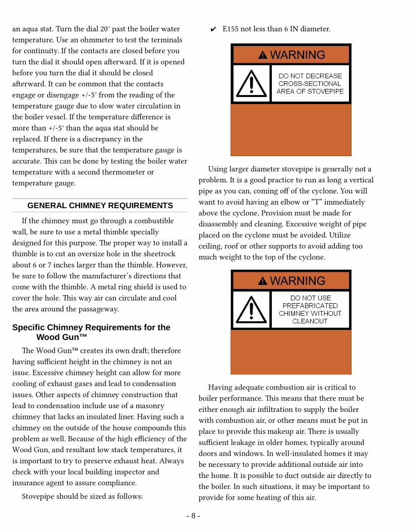
✔ E155 not less than 6 IN diameter.
Using larger diameter stovepipe is generally not a problem. It is a good practice to run as long a verticalpipe as you can, coming off of the cyclone. You will want to avoid having an elbow or “T” immediately above the cyclone. Provision must be made for disassembly and cleaning. Excessive weight of pipe placed on the cyclone must be avoided. Utilize ceiling, roof or other supports to avoid adding too much weight to the top of the cyclone.
Having adequate combustion air is critical to boiler performance. is means that there must be either enough air infiltration to supply the boiler with combustion air, or other means must be put in place to provide this makeup air. ere is usually sufficient leakage in older homes, typically around doors and windows. In well-insulated homes it may be necessary to provide additional outside air into the home. It is possible to duct outside air directly to the boiler. In such situations, it may be important to provide for some heating of this air.
- 8 -

FLUE PIPE
Use only 24 gauge pipe or heavier for flue connections. We recommend stainless steel. Heavy gauge black pipe will not last very long, typically only one or two years. Galvanized pipe is not recommended. When using single wall flue pipe in open areas, assure the pipe passes no closer than 18 inches from combustible walls or ceiling. If the flue pipe must be closer than 18 inches from the nearest wall or ceiling, or if it must go through walls, closets,or boxed-in areas, then U.L. listed insulated flue pipe must be used. Flue pipe that runs along the outside walls of a building must also be U.L. listed insulated pipe, even if it runs along a non-combustible outside wall. is requirement is in place in order to prevent cooling of the flue pipe, which in turn cools the rising smoke and causes condensation and creosote to form quickly.
Do not connect more than one heating appliance to a single chimney. Be sure to check all local codes and your insurance provider’s requirements for any additional restrictions and/or guidelines regarding your flue pipe.
PROPER CHIMNEY CONNECTION
e boiler must be connected to a class A chimney. e recommended method for connecting the boiler to the chimney is to place a T-joint at the top of the vertical section leading from the cyclone. Each joint should be secured with three sheet metal
If a second change of direction is required before entering the chimney a cleanout “T” should be placed at this point also as indicated in Figure 1. Anyhorizontal pipe should be pitched upward toward thechimney at least ¼ in for each foot of horizontal run. Be sure there are at least 18 in clearance between horizontal piping and combustible ceiling. Be sure that the chimney connection pipe extends at least 2 in into the chimney, but does not extend so far into the chimney that it blocks airflow.
In installations where the chimney dra is too strong, the problem may be eliminated by allowing air to pass up the chimney from an auxiliary valve
- 9 -
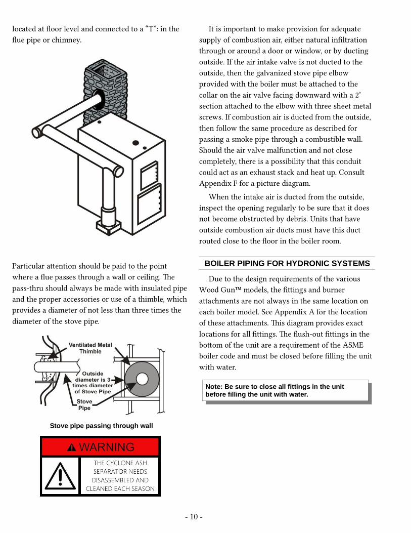
located at floor level and connected to a “T”: in the flue pipe or chimney.
Particular aention should be paid to the point where a flue passes through a wall or ceiling. e pass-thru should always be made with insulated pipeand the proper accessories or use of a thimble, whichprovides a diameter of not less than three times the diameter of the stove pipe.
Stove pipe passing through wall
It is important to make provision for adequate supply of combustion air, either natural infiltration through or around a door or window, or by ducting outside. If the air intake valve is not ducted to the outside, then the galvanized stove pipe elbow provided with the boiler must be aached to the collar on the air valve facing downward with a 2’ section aached to the elbow with three sheet metal screws. If combustion air is ducted from the outside, then follow the same procedure as described for passing a smoke pipe through a combustible wall. Should the air valve malfunction and not close completely, there is a possibility that this conduit could act as an exhaust stack and heat up. Consult Appendix F for a picture diagram.
When the intake air is ducted from the outside, inspect the opening regularly to be sure that it does not become obstructed by debris. Units that have outside combustion air ducts must have this duct routed close to the floor in the boiler room.
BOILER PIPING FOR HYDRONIC SYSTEMS
Due to the design requirements of the various Wood Gun™ models, the fiings and burner aachments are not always in the same location on each boiler model. See Appendix A for the location of these aachments. is diagram provides exact locations for all fiings. e flush-out fiings in the boom of the unit are a requirement of the ASME boiler code and must be closed before filling the unit with water.
- 10 -
Note: Be sure to close all fittings in the unit before filling the unit with water.

Piping the Boiler in Parallel with Another Boiler
e Wood Gun™ may be connected to a heating system supplied by one or more boilers that are already in place. To connect the boiler to the existingboiler run the supply pipe with a flow check from theWood gun and Tee into the supply pipe of the existing boiler. is pipe will carry hot water to the existing boiler when there is no heat demand and will in turn keep the existing boiler from turning on. e return pipe with a circulator pushing toward the Wood gun will Tee into the return line of the existingboiler. It is required that the piping be such that excessive pressure will not be developed in any portion of the boiler or system. e circulator will constantly run when the Wood Gun boiler is on. Wire the circulator to the Wood Gun boiler in such away that when the boiler switch is on the circulator will also run. e power to the Wood gun should then be controlled by an aqua stat located in the supply piping. is aqua stat should be set 10ºF above operating temperature of the existing boiler. at will shut the Wood gun down if it runs out of fuel. e aqua stat will need to have a bypass switch that will allow the wood boiler to have power and enable it to be started so that it can be warmed to its operating temperature.
ere are many possible configurations that allowfor an existing boiler to function as a backup to the Wood Gun™. For sample illustrations of multiple boiler configurations, see Appendix F.
Pressure Relief ValveA pressure relief valve should be inserted into
tapping DD on the E155.
Pressure Relief Valve
Pressure Reducing Fill ValveIf the Wood Gun™ is installed as the primary
boiler, it is necessary to provide for water supply using a pressure regulating valve and backflow prevention valve in the feed water line.
Pressure regulating valve and backflow preventionvalve configuration
Expansion Tank SelectionClosed loop systems require the use of an
expansion tank. Refer to Appendix A: Additional
- 11 -
Note: A length of copper pipe must be connected to the pressure relief valve continuing to a point 6in from the floor as shown in Figure 3 above.

Specifications to determine the water capacity of the Wood Gun™ installed (do not use the BTU rating). e expansion tank or air cushion tank that was originally installed will not likely be adequate for theadditional volume of water added to the system with the inclusion of a Wood Gun™. e tank must be sized based on total water volume and the difference between the low and high temperatures of this water.When properly sized, it will accommodate the thermal expansion of the water being heated withoutcreating an overpressure situation. Some closed loop systems are isolated from an open (atmospheric) sideof the system, or another closed loop, by a heat exchanger. For calculating system volume, only the volume in each respective closed loop is calculated, with each closed loop receiving its own dedicated expansion tank capacity. If the autofill valve engages and adds water to the system when cold, and the boiler subsequently builds too much pressure when hot, you do not have adequate expansion capacity.
RETURN WATER TEMPERATURE
As a rule, water returning to the boiler should be not more than 20º F less than supply water temperature going to the system. A recirculation loop is a requirement to maintain optimum return water temperatures. is would optimally include a thermometer on the return line entering the boiler for monitoring purposes, and a mixing valve to maintain minimum return water temperatures. Return water temperature near or below 140º F
creates the risk of severe condensation issues. is will oen produce unpleasant odors and possible liquid runoff in the boiler room. More seriously, it will lead to creosote formation on heat exchange surfaces and inside the chimney, with accompanying risk of a chimney fire.
- 12 -

Low Water Cutoff
Photo: Low Water Cutoff Installation
e low water cut off should be installed in the supply riser just above the tapping of the boiler., as shown above. Place a Tee fiing 6” above the boiler in the supply line. Install the L.W.C.O. so that it is accessible and the indicator lights can be seen.
Run three wires from the L.W.C.O. to the main control box that corresponds with the wires/terminals in the control box. e wires needed are: Orange, Orange #2, White. ese wires will terminate in the LWCO as follows:
1. e orange wire will be terminated with the black wire and one of the Yellow wires.
2. e orange 2 wire will terminate with the remaining yellow wire.
3. e White or neutral wire will terminate with the white wire in the LWCO.
Terminate the wires in the control box with the corresponding wires (or terminal blocks that correspond with the wire).
1. e Orange wire will terminate on the terminal marked orange.
2. e Orange #2 wire will terminate on the terminal marked orange #2.
3. e White wire will terminate on the terminal marked white, L2 or neutral.
RECOMMENDED BOILER CONTROLSETTINGS
IN HYDRONIC SYSTEMS
e following control seings are recommended for parallel installations:
✔ High limit 200° F✔ Operating control on the rear of the boiler is
180°.
Set the operating control differential set to 15º F unless using cast iron radiators, for which a differential seing of 20º F or more is recommended.
Additional seings may include:
✔ Optional circulator shutdown control 160° F✔ An existing oil/gas boiler 140° F.
On Wood Gun™ models equipped with oil or gas backup, the control seings should be as follows:
✔ High limit = 200° F✔ Operating Limit = 180° – 170° F✔ Burner Control (L6006A) = 150° F
In this way, the oil burner will function as a backup and only fire when the boiler temperature drops below about 150º F. e oil burner may be set even lower if desired to prevent it from firing except when the wood fire is almost completely out.
Wood Gun™ units supplied with automatic switchover (fuel oil only) are provided with a mode switch. When turned to either the “Wood” or “Oil” mode it will fire on the indicated fuel and not switch over. In the “Auto” position it will change from the wood mode to oil when the water temperature falls to the seing on the switchover aquastat (L6006A), and will stay in this mode until manually reset, at which time the boiler may be refueled with wood.
For units equipped with electric backup, follow the procedure outlined above with the exception thatone of the electric element aquastats should be set about 5° F higher than the other. is will prevent all electric elements from being activated at the same time.
- 13 -

BOILER CONDITIONER / SEALANT
AHS provides two boles of Boiler Conditioner/Sealant with the purchase of your boiler.When filling your boiler with water for the first time,mix the contents of each bole with 2 gallons of warm water. Pour into boiler opening. Replace plug. A Material Safety Data Sheet (MSDS) is available upon request.
BOILER PIPING AND CONTROLS FOR LOW PRESSURE STEAM SYSTEMS
Wood Gun™ models E180 and larger are available with steam tappings and controls by special order. When installing a low-pressure steam boiler, be sure that the installation conforms to all state and local codes. All steam boilers will be supplied with a low water cut-off, which fits the ¾ inch tapping on the rear of the boiler. is control must never be hot wired or disconnected since it prevents the boiler from firing should the water level drop below the safe operating level.
A water level gauge glass is also provided to give a visual indicator of the level of water in the boiler. is gauge is located in tapping FF on the rear of the boiler and a section of piping, which originates from a tapping in the top of the boiler near the rear.
An automatic water feeder or combination water feeder/low water control such as a McDonnell-Millermodel 47-2 is required to ensure that the proper water level is maintained. Some states or municipalities require two low water control devices in series. e two controls described above will meet this requirement.
For steam systems other than gravity return consult Alternate Heating Systems for proper controls. Do not aempt to connect two different steam boilers in parallel since the water level in each boiler will not be the same.
Note that steam models are wired differently than hydronic models. See Appendix B for Wood Gun wiring diagrams. Contact Alternate Heating Systems if you need a diagram not included in this manual.
FORCED HOT AIR SYSTEMS (WATER TO AIR COIL IN DUCT)
e Wood Gun™ boiler may be easily adapted to any forced hot air heating system by installing a heatexchange coil in the supply duct. e size and type ofcoil required may be determined aer several factors are determined. ese factors include: the heat output required (BTUH), the capacity of the existing fan blower (CFM) and the size of the duct or plenum where the coil will be installed.
e coil creates increased resistance to air flow, sothis factor must be considered when determining thefinal airflow. Design water temperature is usually 180º F and a desirable output air temperature is 115° -125º F.
- 14 -
Tip: To increase coil performance, increase boiler water temperature.

DOMESTIC HOT WATERCOIL PIPING
e Wood Gun™ may be fied with one or more domestic hot water coils, which thread into 4 inch tapping’s in the boiler. ere are three methods for plumbing the domestic coil. One way is to connect the coil in series with an existing hot water heater.
A second method of plumbing the domestic coil isto connect the coil in parallel with an existing water heater so that the conventional water heater may be used when the Wood Gun™ is not being fired (for example, in the summer). e diagram below indicates how this can be done.
Plumbing – Coil in Parallel
Plumbing – Coil with circulator
- 15 -
OIL BURNER ASSEMBLY
General InformationIf an oil burner is supplied with the Wood Gun™,
connection of fuel lines and the adjustment of the burner should be done by a qualified oil burner technician. e oil burner is normally shipped detached from the Wood Gun™ in a separate box. Refer to the Riello Burners Installation Manual included with your shipment for instructions on configuring the burner. Particular aention should bepaid to the Oil Line Connections section of the RielloInstallation Manual. Ensure that the correct size nozzle is in place on the burner before installing on the boiler. e correct nozzle size for the Riello Oil Burners installed in the E155 is 0.65 gph, 45º, semi-solid.
Oil/Gas Burner Combustion Chamber: Models E155
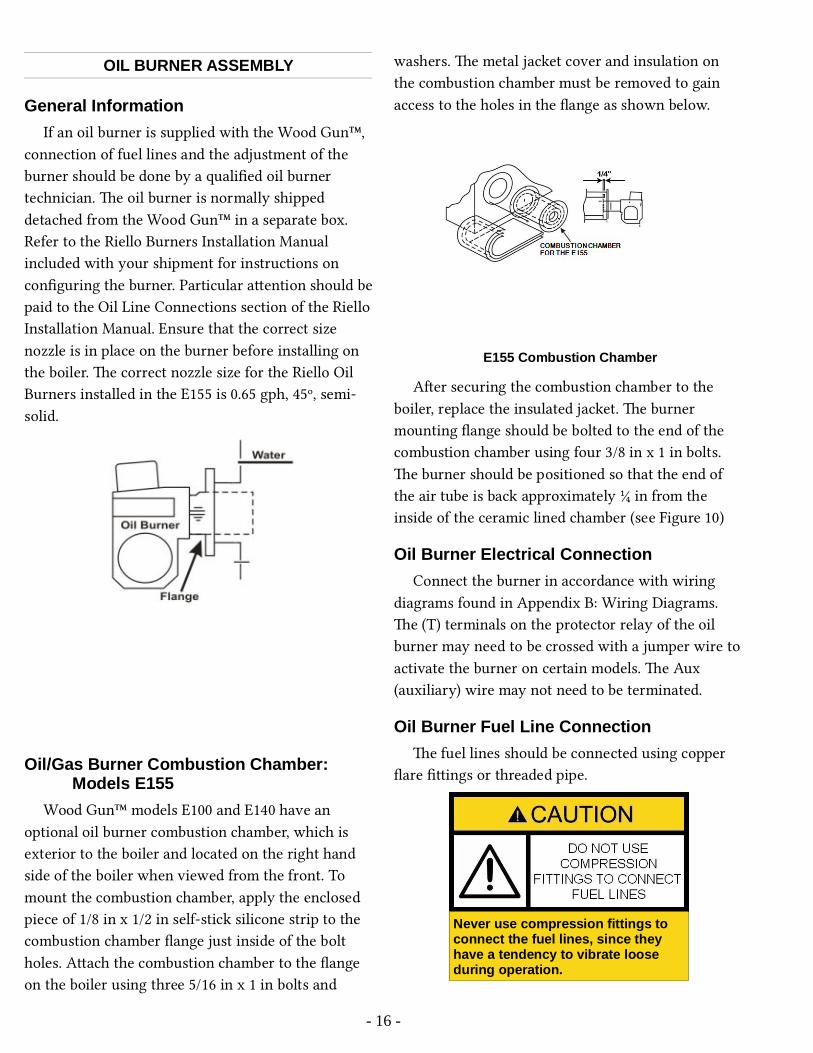
Wood Gun™ models E100 and E140 have an optional oil burner combustion chamber, which is exterior to the boiler and located on the right hand side of the boiler when viewed from the front. To mount the combustion chamber, apply the enclosed piece of 1/8 in x 1/2 in self-stick silicone strip to the combustion chamber flange just inside of the bolt holes. Aach the combustion chamber to the flange on the boiler using three 5/16 in x 1 in bolts and
washers. e metal jacket cover and insulation on the combustion chamber must be removed to gain access to the holes in the flange as shown below.
E155 Combustion Chamber
Aer securing the combustion chamber to the boiler, replace the insulated jacket. e burner mounting flange should be bolted to the end of the combustion chamber using four 3/8 in x 1 in bolts. e burner should be positioned so that the end of the air tube is back approximately ¼ in from the inside of the ceramic lined chamber (see Figure 10)
Oil Burner Electrical ConnectionConnect the burner in accordance with wiring
diagrams found in Appendix B: Wiring Diagrams. e (T) terminals on the protector relay of the oil burner may need to be crossed with a jumper wire toactivate the burner on certain models. e Aux (auxiliary) wire may not need to be terminated.
Oil Burner Fuel Line Connectione fuel lines should be connected using copper
flare fiings or threaded pipe.
- 16 -
Never use compression fittings to connect the fuel lines, since they have a tendency to vibrate loose during operation.

Oil Burner AdjustmentFor proper oil burner adjustment, refer to the
burner installation manual.
Every oil burner contains safety devices that are designed to prevent unsafe operation. When the burner is activated, fuel is pumped through the nozzle in the presence of an ignition arc produced bytwo electrodes and a high voltage transformer. In order to prevent raw fuel from being discharged into the combustion chamber should ignition fail to occur,a CAD cell is employed to “proof” the flame. If the CAD cell does not “see” a flame within a preset time period, usually 20-30 seconds, a relay will shut down the burner and it cannot aempt to re-fire until the reset buon is pressed. When contamination from the wood combustion process coats the CAD cell it interferes with the proper functioning of this safety device.
If the Wood Gun™ is properly cleaned and maintained on a regular basis, then the adverse effects described above are minimized. However, neglect of the unit may result in disappointing performance. It is recommended that in instances
where the owner intends to depend upon the oil burner as the primary fuel source, that the oil burnerbe cleaned and test fired several times to verify that the safety control system is not impaired. If wood is the primary fuel source, with oil a seldom used backup, Alternate Heating Systems strongly recommends the unit be fired on oil periodically to assure that the oil burner will function when needed.
Do not assume that a unit operated solely on wood for an extended period of time will fire on oil without aention.
For proper burner adjustment a combination test kit must be used. It is not likely that the CO2 levels suggested in the burner manual can be achieved, but the net stack temperature will be very low, yielding anet efficiency well in excess of 80 %. Refer to the burner manual for information regarding wiring logic and individual components of the burner.
GAS BURNER ASSEMBLY
Refer to the Riello Burners Installation Manual included with your shipment for instructions on configuring the burner. Gas burners must be installedutilizing manual switchover controls only.
- 17 -
Note: If the oil tank has a two-pipe system, then it is necessary to insert the bypass plug into the burner pump as described in the manual for the oil burner. When using a Riello Burner, always use a two-pipe fuel line system.
Note: It is a good idea to test fire the oil burner when weekly cleaning and maintenance is performed.
NOTE: The Riello gas burner has an air sensor that senses airflow through the burner. When a Riello gas burner is installed, then a variable speed induction fan control may need to be a necessary option.

e burner mounts to the flange on the boiler combustion chamber using three 3/8 in x 1½ in bolts provided. Make sure the gasket provided with the burner is placed between the flange on the Wood Gun™ and the mounting flange of the gas burner. Connect the burner according to the wiring diagram included with your boiler or found in Appendix B: Wiring Diagrams
For larger units consult the special instructions provided in the supplement to this manual.
Before allowing gas that is under pressure into thepiping, all openings from which gas can escape should be closed. Immediately aer turning on the gas, the system should be checked for leaks. is can be done by watching the ½ cubic foot test dial and allowing five minutes to show any movement or by soaping each pipe connection and watching for bubbles. Use a solution of dishwashing detergent andwater for “poor man’s” leak detection or use electronic detectors. Pay aention to any gas odor and follow up any observed odor with a check of all connections for leaks. Remember that ventilating an area when correcting a leak is normally a good idea. Keep in mind that propane is heavier than air and natural gas is lighter than air.
Please see the Riello Burner Installation Manual section entitled Seing up the Burner for information on gas burner adjustment.
OIL AUTOMATIC SWITCHOVER ANDLOCKOUT CONTROL
e Automatic Switchover option automatically switches the Wood Gun™ into oil mode if it is unableto maintain temperature while firing with wood. e most likely scenario causing the switchover to take place is when the boiler has used up the wood fuel. e Wood Gun will also switchover to oil if the fire goes out, as may occur when the boiler has been inactive for hours, and the refractory has cooled to below the kindling temperature for wood. In this case, the boiler must be manually switched back to wood mode, and manually relit, in order to resume wood burning.
e Lockout feature prevents needless cooling from the induction fan running while in oil mode. Once this feature is engaged, the boiler switches to oil mode and will function continuously as an oil-fired boiler until manually switched back to wood mode. Automatic switchover is not available for use with gas backup. See Appendix B for wiring logic forunits equipped with this feature.
SMOKE FLAP
e smoke flap must be installed before operating the boiler.
- 18 -
Note: Advice offered in this manual is NOT a substitute for securing the services of a professional installer.

e smoke flap will help hold back some of the smoke when the front load door is opened, and provide some protection against flashovers in the fuel chamber.
Photo: (Smoke flap installed)
- 19 -

Operating InformationPlease read this entire manual before operating
the boiler. It contains important requirements and instructions must be followed for safe and satisfactory operation of the boiler.
e boom of the fuel chamber contains dense cast refractory blocks. e refractory is baked in a kiln at the factory to dry out nearly all moisture before it is placed in the boiler, but it does not reach maximum strength unless heated to operating temperature gradually (cured).
On units that have a backup oil or gas burner, the green indicator light will only be on when the fan is running and the oil burner is not firing. If the
indicator light does not come on when the purge timer is activated, it means the oil/gas burner is firing and the door must not be opened.
Once the Wood GunTM has switched automaticallyor has been manually switched to a backup fuel, switching back to wood must be performed manually. is is accomplished by shuing the main switch off, turning the fuel selector switch back to wood, turning the main switch to on, and rekindling the boiler in the same manner as when the boiler was initially fired with wood. Be sure to only open the door when the green light is on. In order to permit the unit to continue firing in the wood mode, it cannot be switched to the “auto” position until boiler temperature has exceeded the seing of the switchover aquastat.
- 20 -
NOTE: It is recommended that several small charges of wood be used initially to ensure that maximum durability of the refractory lining is achieved.

STARTING A FIRE: SWITCH POSITIONS
Switch Positions: Cold Boiler Start-upBefore Lighting
After Lighting Water Temp Risen above 150º
Boiler Switch Off On On
Start/Run Switch*
Start Start Run
*Units with Low Temp Shutdown only
FUEL TYPE
The Wood Gun is designed to burn split or unsplit wood
e Wood gun is designed to burn log wood. e Wood gun is able to burn both hard wood and so wood fuel. Keep in mind that hardwood is typically abeer fuel. Hardwood will usually give you longer burn times than sowood, due to greater energy density per unit volume. Oak, Maple, and Cherry are a few of the hardwood types that can be burnt. Cedarfir and pine are a few of sowood species that can beburnt. A well managed Wood Gun will not produce creosote from burning sowood.
STARTING A FIRE: PROCEDURE
Starting a fire in the Wood GunTM is similar to starting a fire in any wood fired boiler with a few important differences. Because the Wood Gun incorporates a downward dra, successful fire starting requires recognizing that fact and layering kindling accordingly. Place kindling wood on the refractory in a lengthwise orientation. Add a layer of crumpled up newspaper followed by another small layer of kindling. Light the paper. Turn on the boiler switch. When the kindling is burning well, add more (and larger) pieces of wood.
When firing a cold boiler, it is important to concentrate heat next to the refractory. e Wood GunTM depends on high refractory temperatures for driving the gasification process. Using drier, smaller wood will help to accomplish this. Add larger pieces only aer the fire is well established. Only fill the fuel storage area aer the refractory has reached good gasification temperatures. Keep in mind that a small intense fire is preferable to a large smoldering one to reduce the amount of creosote deposition. is will be accomplished by building the initial fire with wood no higher than the door frame. When the starting charge is burning hot, add the rest of the
- 21 -
Note: Always place wood in the Wood GunTM lengthwise (from front to back). Never place wood in the fuel storage area crosswise.

charge in sufficient quantity to last for up to ten hours. Longer cycles are possible, but you will want to plan for utilizing shorter burn cycles periodically to provide for good firebox management. Best practices include keeping ash and charcoal build-up to a minimum. When demand is moderate to low, simply load charges of fuel that are just adequate for the length of the anticipated burn cycle.
SEQUENCE OF OPERATIONe boiler regulates itself to operate in an efficient
manner and at the same time be able to keep up withhigh demand situations. e boiler will shut down at 180F. It will sit dormant until enough demand is usedto drop the water temperature to 165F. At that point the boiler will turn on. e actuated damper will begin to open and the blower motor will turn on. eunit will operate on high for three minutes at which point it will reduce the motor speed to normal. If at any point the boiler temperature falls below 152F theblower motor will switch into high. e unit will continue to operate in this fashion until it overcomesdemand and shuts down at 180F. If the boiler is equipped with the Low Temp Shutdown option the unit will shut down because of low water temperature at 140F.
A manually operated damper located at the rear of the unit can be temporarily closed in a proportional fashion to slow the burn rate of dry wood. Be sure to read the section on dry fuel, and about the EPA Side Tunnel Plug, a lile further in themanual.
Charging the Boiler with Wood: Manual Feed
When reloading the Wood Gun™, it is a good ideato use the ash rake to make sure that all of the centerslots are open and free from ash and charcoal before adding more wood. Such raking is required more oen when using sowood, or any wood with a highash content. Wood bark has a very high ash content relative to the centers of wood pieces. When using hardwood, clear the slots at least daily. Clear the slots by raking charcoal pieces away from the slots. Aer raking the charcoal pieces away from the slots, rake ash into the slots, thus aiding the process of allowing the induction fan to pull the ash through. A vacuum that is rated for ash removal can also be used for removing ash that does not contain live embers.
- 22 -
Long burn cycles will also lead to accumulation ofcharcoal in the fuel storage area. Excess charcoal willtend to block airflow through the slots in the center brick. Furthermore, so, crumbly charcoal can also be pulled through the refractory, resulting in tiny, live embers being emied into the cyclone.
Back-Puffing PreventionChecklist✔ Use fuel with higher moisture content,
✔ Load weer fuel on the top of your fuel charge
✔ Use a good percentage of full rounds, as large as 10 inches or more in diameter
✔ Stack wood tightly, using a combination of full rounds and split pieces to form a more solid block of fuel inside the fuel chamber
✔ Utilize shorter burn cycles, to prevent over drying of the fuel charge that occurs with long cycles
✔ Use the EPA Side Tunnel Plug (described below)
One way to appraise what is going on inside the boiler is to open the air valve box during an active firing cycle (or to look through an optional Air ValveView Port) and observe the fire. If you see flames shooting upward inside the fuel chamber, consider the above checklist items as your action list for preventing back puffing. Remember, the Wood Gun utilizes a down dra design, and optimum combustion takes place when the flame is properly inverted.
EPA Side Tunnel Refractory Plugis plug fits into one of the side refractory
tunnels, blocking passage of hot combustion gasses. is results in one side of the refractory lining the boom of the fuel chamber remaining comparativelycooler than the other. Less heat on that side means a lower rate of pyrolysis, and lower total amounts of wood gas production. If not in place unwanted backpuffing, and lengthened warm up times may occur.
- 23 -
Note: Guard against charcoal accumulation in your Wood GunTM by keeping burn cycles at less than 10 hours. Utilize occasional short cycles, as short as 4 hours, for good firebox management.
Note: Spent ash should not be allowed to build upon or in the refractory. Any ash buildup will insulate the fuel charge from the heat generated in the refractory, slowing the rate of gasification, and thereby reducing heat output.

EPA Side Tunnel Plug Install
WOOD FUEL CHARACTERISTICS AND WOODSTORAGE
Although the boiler will burn green or wet wood, this practice is discouraged because of the substantialamount of heat energy required to evaporate the moisture before combustion can take place. When first cut, the moisture content of wood may range from 40% to 60% as compared with air-dried wood at 25% to 35%. Each extra 25% of moisture represents approximately five gallons of additional water that must be evaporated and passed out the chimney for each 160-pound charge of wood. e heat that must be used to evaporate any extra water is heat that is then not available for your heating application, lowering significantly the maximum heat output of the boiler. It is advantageous to let the sun remove that extra 100 to 250 gallons of water found in a cord of wood. Generally, wood should be stored outdoors
in a dry place with only a limited supply kept indoors.
Using wood that has a moisture content of greaterthan 30% can be detrimental to the operation of the boiler. Results of using wood with too high of a moisture content are likely to include loss of BTU output, reduced efficiency, and condensation issues. Using high moisture wood will reduce the service lifeof carbon steel boilers. It is recommended to have at least one week worth of fuel inside and kept out of the weather. Do not store fuel within the appliance installation clearances or within the space required for fueling, ash removal, and other routine maintenance operations.
Do not store wood within the recommended clearances of the boiler or within the space required for loading wood and ash removal.
LOW WATER TEMPERATURE OPTION
When the Low Water Temperature Shutdown (LTS) switch is in the “ON” position the low temperature function will allow the boiler to operate normally until the water temperature falls below the set point of the LTS aquastat (located at the rear of the unit). e factory seing on this aquastat is 145F.When the boiler water temperature is at or below theset point the boiler will shut down. e reason for this is to keep the boiler from cooling the system down when the boiler is out of fuel. When the boiler is running with no fire the cool air moving through the unit will cool the water. is is especially inefficient if there is a backup boiler (in most cases oil or gas fired) is trying to maintain heat in the system.
- 24 -
Note: When starting a fire in a Wood Gun™ equipped with an oil or gas burner, it is first necessary to switch the fuel selector control to “wood” mode.

When it is time to start the boiler, load the boiler as you would for a normal start. When it is time to have the dra fan turn on, simply push the black start buon. e start buon will activate the boiler and will allow the unit to run for two hours while below the LTS set point. Within these two hours the boiler will be able to heat up enough to raise the water temperature above the LTS set point. At no point does this function override any other limit controls on the boiler. If with the two hour time limitthe boiler water temperature would reach the operating set point the boiler will shut down as normal.
COOL DOWN CYCLE
e Wood Gun is to run a cool down cycle. When the boiler is operating for a period of six minutes or more, the fuel inside will begin pyrolysis. In the design of the Wood Gun, the boiler will use this process to produce heat efficiently. When the boiler reaches the operation temperature limit, it will shut down and enter into a dormant state. At this point, there are combustible gases in the fire box. Allow theWood Gun fieen minute cool down cycle. e cool down cycle begins as soon as the boiler shuts down and should last for fieen minutes. During this period, the boiler should be started.
WOOD FUEL CHARACTERISTICS AND WOODSTORAGE
Although the boiler will burn green or wet wood, this practice is discouraged because of the substantialamount of heat energy required to evaporate the moisture before combustion can take place. When the first cut, the moisture content of wood may rangefrom 40 to 60% as compared with air-dried wood at 25% to 35%. Each extra 25% of moisture represents approximately five gallons of additional water that must be evaporated and passed out of the chimney for each 160 pound charge of wood. e heat that must be used to evaporate any extra water, is heat that is then not available for your heating application. is significantly lowers the maximum
heat output of the boiler. It is advantageous to let thesun remove that extra 100 to 250 gallons of water found in a cord of wood. Generally, wood should be stored outdoors in a dry place with only a limited supply kept indoors.
Using wood that has a moisture content of greaterthan 30%, can be detrimental to the operation of the boiler. Results of using wood with too high of a moisture content are likely to include loss of BTU output, reduced efficiency, and condensation issues. Using high moisture wood will reduce the service lifeof carbon steel boilers. It is recommended to have at least one week worth of fuel inside and kept out of the weather. Do not store fuel within the appliance installation clearances or within the space required for fueling, ash removal, or other routine maintenance operations. e EPA has made availablea few videos to help you understand what fuel is bestand why. ese videos can be viewed online at the following addresses:
EPA Burnwise Program: hp://www.epa.gov/burnwise
How to use a Moisture Meter Video: hp://www.youtube.com/watch?=jMsWGgRcnm0
Wet Wood is a Waste Brochure: hp://www.epa.gov/burnwise/pdfs/wetwoodwastebrochure.pdf.
REMOVAL AND DISPOSAL OF ASHES
Ashes should be placed in a metal container with a tight fiing lid. e closed container of ashes should be placed on a non-combustible floor or on
- 25 -
the ground well away from all combustible materials,pending final disposal. If the ashes are disposed of byburial in soil or otherwise locally dispersed, they should be retained in a closed container until all cinders have thoroughly cooled to prevent inadvertently starting a fire.
CONDITIONING OF BOILER WATER
Instructions for feed water treatment as prepared by a competent feed water chemist should be followed. Do not experiment with homemade treatment methods or compounds.
Representative samples of feed water and boiler water need to be analyzed frequently to ensure that they are within specified ranges.
Strict monitoring of boiler water is more important for steam applications (and for open systems) where there is a continuous influx of makeup water. For hydronic units, typical installations utilize the boiler water in a closed system, which only occasionally requires the addition of makeup water over the lifetime of the boiler.
e pH value of your boiler water is a number between zero and fourteen. Values below seven are acidic while values above seven are basic.
e pH factor is the most important factor influencing scale forming or the corrosive tendenciesof boiler water. It should be adjusted to between a minimum of 9.0 and 11.0 to prevent acidic corrosion of boiler tubes and plates and to provide for the precipitation of scale forming salts.
Below a pH of 5.0 the water is acidic enough to dissolve the steel boiler plates. Under these conditions the steel gradually becomes thinner and thinner until it is destroyed. At a pH between 5.0 and9.0 piing of steel plates is likely to occur at a rate dependent upon the amount of dissolved oxygen in the boiler.
Dissolved OxygenAeration of city water supply is frequently used to
remove noxious gases, however, aeration results in saturation of the water with oxygen. A majority of corrosion problems are directly related to the quantity of dissolved oxygen in the boiler water. Elimination of the corrosive effect of dissolved oxygen can be accomplished either directly or chemically.
Direct or mechanical removal of dissolved oxygenis done through the use of a de-aerator. Chemical de-aeration is done through the introduction of specific chemicals in the boiler to react with the oxygen. e dissolved oxygen content should be maintained at a minimum but at no time should it exceed 0.007 mg/l.
Sodium sulfite is commonly used for the chemical removal of dissolved oxygen within the boiler water. To assure the rapid and complete removal of the oxygen entering the boiler feed water system the concentration of sulfite in the boiler should be maintained at a minimum of 120 ppm.
- 26 -
Note: For hydronic situations where the system isnot closed, the following water treatment guidelines still apply and become even more critical!
Note: The guidelines in this section are to be used in conjunction with the advice of a water treatment specialist.

Solids (Primarily for Steam Boilers)High boiler solids will lead to foaming, priming,
surging, carry over or boiler sludge in steam boilers. Occasional blow downs of the boiler may remedy these conditions. We recommend you utilize the services of a local professional plumbing service for this boiler maintenance task.
(See hp://www.p2pays.org/ref/34/33 027.pdf)
Solids can be categorized as either suspended or dissolved. Suspended solids are those that can be removed by filtration while dissolved solids are in solution with the water.
e best way to determine the dissolved solid content of boiler water is a conductance test. e conductance of boiler water varies proportionately with the amount of various ionized solids present.
Another way to determine the dissolved solids content is to measure the chlorides present in the boiler water. e chloride test is less sensitive than the conductance test for measuring small concentrations of dissolved solids. e results of bothtests should be averaged for accuracy.
Alkalinitye alkalinity of boiler water should be
sufficiently high to protect boiler steel against acidic corrosion, but not so high as to cause carryover
(basic) corrosion. A minimum value for alkalinity foradequate protection is 200 ppm CaCO3.
High boiler alkalinity (in excess of 700 ppm CaCO3) should be avoided. Values higher than this can cause the steel to become brile.
PhosphatesPhosphates are used to counteract hardness in the
boiler water. It is important to maintain a pH of at least 9.5 to not hinder the reaction of the phosphates with calcium hardness. Try to keep the concentrationof phosphates in the water to 30-50 ppm to enable complete reaction.
Hardnesse hardness of water is caused by calcium and
magnesium ions. Water hardness will vary greatly throughout the country depending on the source of the water. In boilers, hard water can cause the formation of scale and sludge or mud. Total hardnessshould not exceed 50 ppm.
OilsEvery effort should be made to prevent oils from
geing into the boiler water. Oil causes foaming or combines with suspended solids to form a sludge, which can cause the overheating of boiler plates. If oil does get into the boiler, the boiler should immediately be taken out of service and thoroughly cleaned.
- 27 -

Maintenance
WEEKLY CLEANING PROCEDURE
Following is the recommended procedure for weekly cleaning:
1. Open front inspection door.
2. Place an ash receiver under the refractory at thefront inspection door opening.
3. Use the ash rake to pull the ash from the center tube.
4. Inspect the outside refractory tunnels for ash buildup and remove with ash rake if necessary.
5. Inspect the refractory center plug that is inserted in the front of the combustion chamber (center refractory tube) and verify that it properly seals the front access opening.
7. Scrape condensation and creosote build-up from inside the air intake manifold using ash rake.
On models with dual dra, use a puy knife or scraper inside the firebox.
8. Open the dra valve cover and inspect the valvegasket disk for evidence of air leakage. e disk should have some wobble, so it can move and find itsown seal. See “Air Valve Cleaning and Maintenance” below.
9. Inspect the fuel chamber and remove any ash residue. Pay special aention to corners as ash can easily become trapped here.
10. Remove ash pan from the cyclone separator and dispose of its contents.
11. Clean excessive ash out of fire box.
Air Valve Cleaning and Maintenance
1. Insert supplied hex key wrench in center as shown in photo.
2. Rotate in the direction indicated on cover.
3. When opened to the desired position, hold the hex key wrench to prevent the spring return from moving actuator.
4. With the hex key wrench held in place, use a screwdriver to turn the gear train lock pin in the indicated direction. Slowly allow the hex key wrenchto rotate backwards until the detent is reached. At the detent position, the pin will lock the motor in
- 28 -
Note: The front of the center combustion chamber must be properly sealed to prevent gas from being drawn directly into the heat exchangerthereby bypassing the refractory tunnels.

place. In the locked position, cleaning and or replacement of the air valve disc can be performed.
5. To release the actuator, use the hex key wrench and rotate in the open direction ¼ turn. e lock is spring loaded to release. Remove the hex key wrenchand allow the valve to close.
e air valve should be inspected and cleaned weekly to ensure that it is sealing properly. A leakingair valve or load door can produce a number of undesirable consequences, including a low smoldering fire. When the air valve is open and the unit is operating, moisture released from the fuel willcondense when contact is made with cooler combustion air. Moisture and creosote can collect on the gasket disk and on the end of the air valve tube and in time produce a deposit that prevents the gasket from sealing tightly. Clean off any deposit on the gasket disc with a cloth soaked in warm water and detergent. Do not scrape with a knife or other metal scraper as you may damage the silicone rubberseal. Clean off any deposit on the end of the tube by using a puy knife. Any accumulation in the tube should also be removed by using the ash rake as described in Step 7 of Weekly Cleaning Procedure.
If the silicone rubber gasket shows evidence of deterioration it should be replaced. When requesting a replacement, be sure to specify the size (diameter) of gasket you require.
To replace the gasket simply remove the center bolt and nut as indicated in the exploded assembly inthis manual. Do not firmly tighten the nut on re-installation as the new gasket needs some slight wobble to seal properly over the air inlet tube.
YEARLY CLEANING
Following is the recommended procedure for yearly cleaning:
1. Clean the heat exchanger.
✔ Remove the dra fan assembly.✔ Use a wire brush or scraper to cleanout the
heat exchanger.
2. Clean the cyclone ash collector.
✔ Remove the top connecting flange from the cyclone.
✔ Clean the inside of the main body and funnel of the cyclone with a wire brush.
✔ Clean the tube that connects the cyclone to the boiler.
✔ Clean the boiler exit port where the cyclone aaches.
AIR VALVE MOTOR REPLACEMENT
Removing Old Damper Motor1. Using the supplied Allen wrench, crank the
motor to the full open position.
2. us a 10 mm wrench to loosen the mounting bolt.
3. Remove Motor.
Installing the New Damper Motor
2. Place motor onto air valve.
- 29 -
Note: Before starting this procedure make sure that the spring return will operate in the correct direction. To change the direction, just remove the clip that holds the clamp in place. Pull the clamp out flip the motor over and reinstall the clamp making sure that the arrow is pointing at the 0º mark. Reinstall the clip.

3. Manually move the air valve disc to the open position, (see Figure 12) ensure that the jaws on the clamp align with the contour of the sha as shown inFigure 11.
4. Tighten 10 mm bolt.
5. Using the Allen wrench, release the lock. is isaccomplished by rotating the wrench in the directionof the arrow one quarter turn and then let go. e motor will then rotate to the closed position.
6. Inspect to insure that the air valve is sealed properly. e disc should have pressure allowing for a complete seal against the air intake collar.
7. It is very important that when placing the red end cap on the motor. e pins must align properly. If the pins do not align properly you will experience issues as such.
✔ Motor may not operate.✔ Green Indicator light may not turn on when
damper is in the open position.
Air Valve Motor Clamp Alignment
Air Valve Disk in Open Positioning
DOOR ADJUSTMENT
For proper operation of the Wood Gun™, it is important to have an effective seal of the loading door and cleanout door. All have a simple adjustmentmechanism on the hinge plate and latch keeper that permits the door to be adjusted as the gasket compresses during service. To adjust the hinge, open the door, loosen the bolts that hold the hinge plate, and bump the door toward the doorframe and tighten the bolts. Be careful not to tighten so much as to prevent the latch side from closing properly.
- 30 -
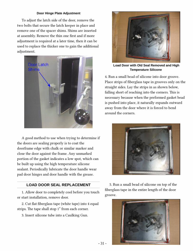
Door Hinge Plate Adjustment
To adjust the latch side of the door, remove the two bolts that secure the latch keeper in place and remove one of the spacer shims. Shims are inserted at assembly. Remove the thin one first and if more adjustment is required at a later time, then it can be used to replace the thicker one to gain the additional adjustment.
A good method to use when trying to determine ifthe doors are sealing properly is to coat the doorframe edge with chalk or similar marker and close the door against the frame. Any unmarked portion of the gasket indicates a low spot, which can be built up using the high temperature silicone sealant. Periodically lubricate the door handle wear pad door hinges and door handle with the grease.
LOAD DOOR SEAL REPLACEMENT
1. Allow door to completely cool before you touchor start installation, remove door.
2. Cut flat fiberglass tape (white tape) into 4 equal strips. e tape shall stop 1” from each corner.
3. Insert silicone tube into a Caulking Gun.
Load Door with Old Seal Removed and HighTemperature Silicone
4. Run a small bead of silicone into door groove. Place strips of fiberglass tape in grooves only on the straight sides. Lay the strips in as shown below, falling short of reaching into the corners. is is necessary because when the preformed gasket bead is pushed into place, it naturally expands outward away from the door where it is forced to bend around the corners.
5. Run a small bead of silicone on top of the fiberglass tape in the entire length of the door groove.
- 31 -
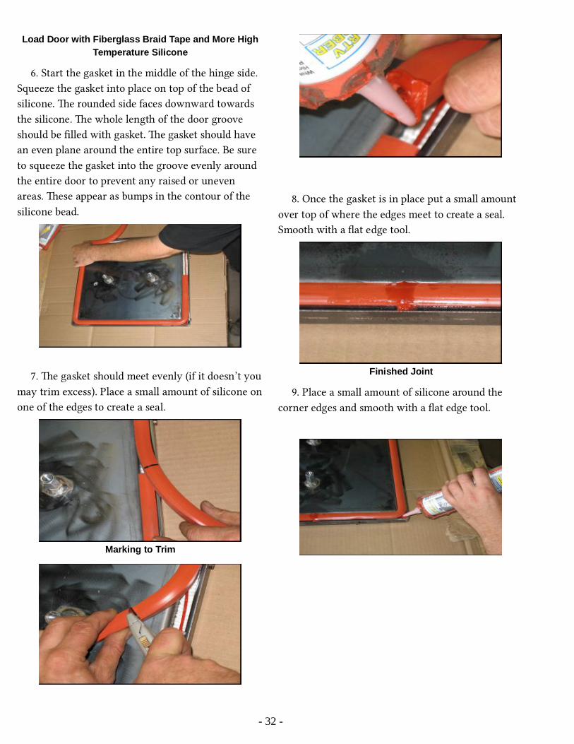
Load Door with Fiberglass Braid Tape and More HighTemperature Silicone
6. Start the gasket in the middle of the hinge side. Squeeze the gasket into place on top of the bead of silicone. e rounded side faces downward towards the silicone. e whole length of the door groove should be filled with gasket. e gasket should have an even plane around the entire top surface. Be sure to squeeze the gasket into the groove evenly around the entire door to prevent any raised or uneven areas. ese appear as bumps in the contour of the silicone bead.
7. e gasket should meet evenly (if it doesn’t youmay trim excess). Place a small amount of silicone onone of the edges to create a seal.
Marking to Trim
8. Once the gasket is in place put a small amount over top of where the edges meet to create a seal. Smooth with a flat edge tool.
Finished Joint
9. Place a small amount of silicone around the corner edges and smooth with a flat edge tool.
- 32 -
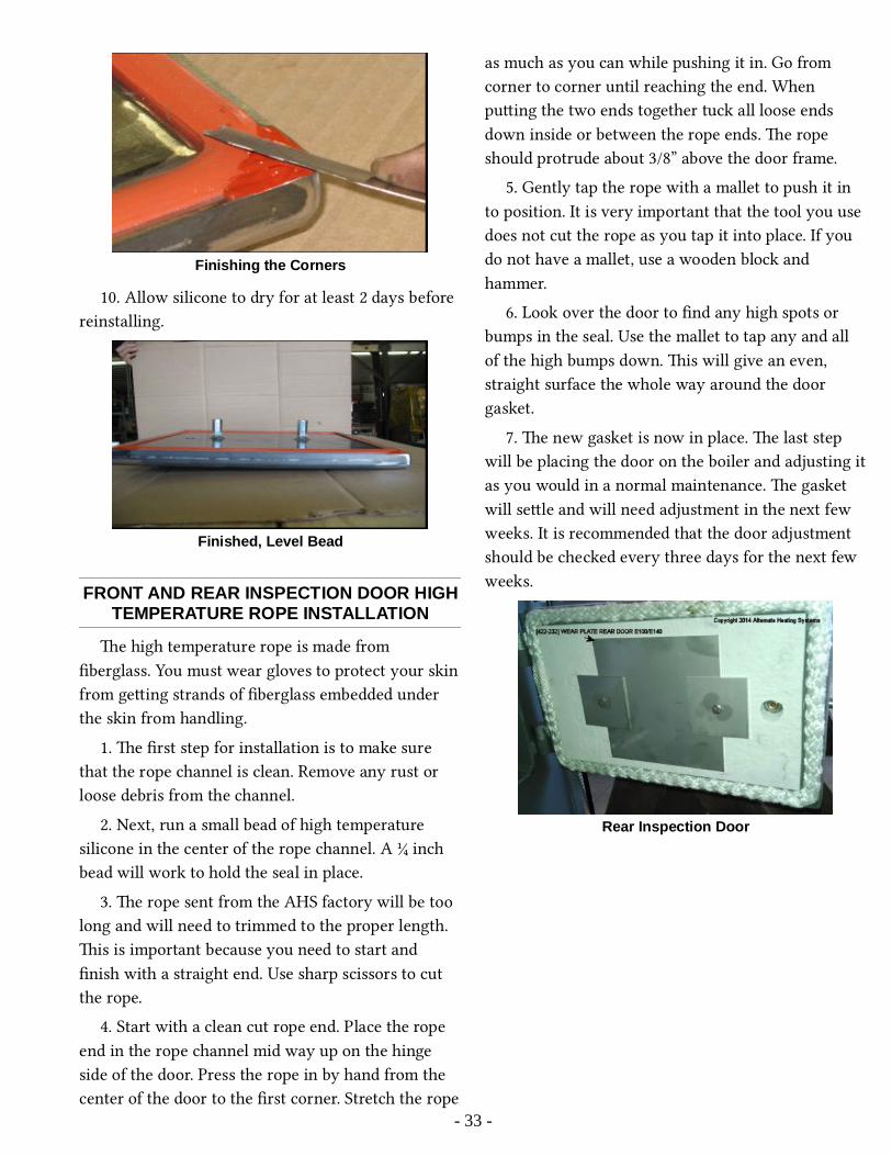
Finishing the Corners
10. Allow silicone to dry for at least 2 days before reinstalling.
Finished, Level Bead
FRONT AND REAR INSPECTION DOOR HIGHTEMPERATURE ROPE INSTALLATION
e high temperature rope is made from fiberglass. You must wear gloves to protect your skinfrom geing strands of fiberglass embedded under the skin from handling.
1. e first step for installation is to make sure that the rope channel is clean. Remove any rust or loose debris from the channel.
2. Next, run a small bead of high temperature silicone in the center of the rope channel. A ¼ inch bead will work to hold the seal in place.
3. e rope sent from the AHS factory will be too long and will need to trimmed to the proper length. is is important because you need to start and finish with a straight end. Use sharp scissors to cut the rope.
4. Start with a clean cut rope end. Place the rope end in the rope channel mid way up on the hinge side of the door. Press the rope in by hand from the center of the door to the first corner. Stretch the rope
as much as you can while pushing it in. Go from corner to corner until reaching the end. When puing the two ends together tuck all loose ends down inside or between the rope ends. e rope should protrude about 3/8” above the door frame.
5. Gently tap the rope with a mallet to push it in to position. It is very important that the tool you use does not cut the rope as you tap it into place. If you do not have a mallet, use a wooden block and hammer.
6. Look over the door to find any high spots or bumps in the seal. Use the mallet to tap any and all of the high bumps down. is will give an even, straight surface the whole way around the door gasket.
7. e new gasket is now in place. e last step will be placing the door on the boiler and adjusting itas you would in a normal maintenance. e gasket will sele and will need adjustment in the next few weeks. It is recommended that the door adjustment should be checked every three days for the next few weeks.
Rear Inspection Door
- 33 -

Front Inspection Door
FAN ASSEMBLY
e fan-motor assembly may be removed by loosening the nuts from the studs.
Direct-drive fan attached to boiler
If the fan assembly gasket is damaged, all of the old material must be removed and a new gasket inserted. Use only 5/8 in diameter high-density fiberglass rope.
On units that have a sha drive fan, the motor bearing will need to be replaced approximately everytwo years. On belt drive fans, the pillow block bearings and belt should be checked every three months. Aer the initial burn of two to six hours shut the boiler down and re-tighten the pillow block bearing set screws. To tighten the fan belt, loosen thefour bolts that hold the motor to the bracket. Slide the motor down and re-tighten, being careful that the motor is properly aligned with the fan sha. Some models have a hinged motor mount with adjusting screws. To check for proper alignment of the pulleys, use a straight edge lying across both pulleys.
- 34 -
Note: Pillow block fan shaft bearings are permanently sealed. Do not force grease into the grease fittings as you will break the seal and grease will run out when heated. DO NOT use a clay based grease in the pillow block bearings. A good synthetic grease is the best option. Most bearing failures are due to greasing too soon, toooften, too much or with clay base grease.

DIRECT DRIVE FAN BEARINGREPLACEMENT PROCEDURE
Make sure the power is turned off and/or disconnected. Disconnect the wire from the motor. Remove the motor end cap (3 screws). Remove the motor assembly by removing four 3/8” locknuts located along the outer edge of the motor mounting plate.
Fan Assembly Mount Points
It is a good idea to mark orientation of components for reassembly.
Mark Assembly Orientation
Place the fan assembly on your workbench with the fan facing up. Remove the two set screws from the fan hub. It might be a good idea to let a good
penetrant soak down into the area between the hub and the sha. Leing it soak in for an hour or longer is recommended.
Fan Hub Set Screws
At this point, you have a choice of two methods for removing the fan. You may use a separate nut and jaw type puller, or you may use the economical AHS Fan Puller Tool. e photos below show each inturn, respectively. A bit of heat on the fan hub from apropane torch may be necessary.
Screw a one inch nut onto the threaded hub of thefan:
One Inch Nut for Pulling Fan
Using a jaw type puller, remove the fan from the motor sha:
Jaw Puller at the Ready
Or, use the AHS Fan Puller:
- 35 -

AHS Fan Puller Tool
AHS Fan Puller Tool at the Ready
Remove the (4) 5/16” nuts and washers from the motor plate allowing you to remove the abrasion shield and the heat shield from the motor plate. Be careful when removing the ceramic heat shield. It is very fragile. It is advisable to use a puy knife to separate the heat shield from the motor plate.
Separate Heat Shield from Motor Mount Plate
To remove the motor from the motor mounting plate use an allen wrench to remove the four motor mounting bolts that are counter sunk into the motor plate.
Closeup of Motor Mounting Bolts
To separate the motor housing you must remove the four bolts from the end of the motor opposite of the sha. ese bolts have a 5/16 bolt head.
Motor Frame Assembly Bolts
Once these bolts are removed, tap the mounting end of the motor on the side with a rubber mallet, or use a regular hammer along with a block of wood. is will separate the bearing housing (end shield) from the motor body.
- 36 -

Loosening Motor End Shield from Motor
e end shield, along with the armature, can then be lied gently out of the motor frame. Be sure that the beveled waster remains inside the motor housing.
Lifting the End Shield with Armature
Removing the two screws located beside the sha will allow you to separate the sha, with the still aached bearing, from the end shield.
Loosening Screws Securing Bearing to End Shield
Use a pulley puller, or our custom bearing puller tool [01-100-80 101] to remove the bearing from the sha. You can use it on the motor bearing on either end of the sha. e bearing on the sha end is the one needing replacement in most instances. You mayby routine choose to replace the bearing on the fan end every other time you replace the sha bearing.
Jaw Puller at the Ready on Motor Bearing
Place the new bearing on the sha and drive it on with a hammer or mallet and a 3/4” pipe until it is fully seated. Use of the properly sized pipe or tube
- 37 -
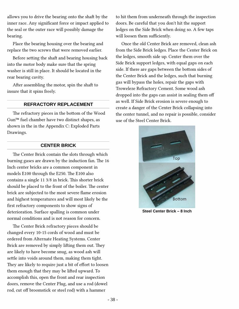
allows you to drive the bearing onto the sha by the inner race. Any significant force or impact applied tothe seal or the outer race will possibly damage the bearing.
Place the bearing housing over the bearing and replace the two screws that were removed earlier.
Before seing the sha and bearing housing back into the motor body make sure that the spring washer is still in place. It should be located in the rear bearing cavity.
Aer assembling the motor, spin the sha to insure that it spins freely.
REFRACTORY REPLACEMENT
e refractory pieces in the boom of the Wood Gun™ fuel chamber have two distinct shapes, as shown in the in the Appendix C: Exploded Parts Drawings.
CENTER BRICK
e Center Brick contain the slots through which burning gases are drawn by the induction fan. e 16Inch center bricks are a common component in models E100 through the E250. e E100 also contains a single 11 3/8 in brick. is shorter brick should be placed to the front of the boiler. e centerbrick are subjected to the most severe flame erosion and highest temperatures and will most likely be the first refractory components to show signs of deterioration. Surface spalling is common under normal conditions and is not reason for concern.
e Center Brick refractory pieces should be changed every 10-15 cords of wood and must be ordered from Alternate Heating Systems. Center Brick are removed by simply liing them out. ey are likely to have become snug, as wood ash will sele into voids around them, making them tight. ey are likely to require just a bit of effort to loosen them enough that they may be lied upward. To accomplish this, open the front and rear inspection doors, remove the Center Plug, and use a rod (dowel rod, cut off broomstick or steel rod) with a hammer
to hit them from underneath through the inspection doors. Be careful that you don't hit the support ledges on the Side Brick when doing so. A few taps will loosen them sufficiently.
Once the old Center Brick are removed, clean ash from the Side Brick ledges. Place the Center Brick on the ledges, smooth side up. Center them over the Side Brick support ledges, with equal gaps on each side. If there are gaps between the boom sides of the Center Brick and the ledges, such that burning gas will bypass the holes, repair the gaps with Troweleze Refractory Cement. Some wood ash dropped into the gaps can assist in sealing them off as well. If Side Brick erosion is severe enough to create a danger of the Center Brick collapsing into the center tunnel, and no repair is possible, consider use of the Steel Center Brick.
Steel Center Brick – 8 Inch
- 38 -
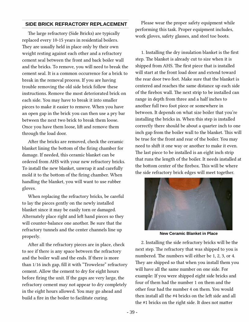
SIDE BRICK REFRACTORY REPLACEMENT
e large refractory (Side Bricks) are typically replaced every 10-15 years in residential boilers. ey are usually held in place only by their own weight resting against each other and a refractory cement seal between the front and back boiler wall and the bricks. To remove, you will need to break thecement seal. It is a common occurrence for a brick to break in the removal process. If you are having trouble removing the old side brick follow these instructions. Remove the most deteriorated brick on each side. You may have to break it into smaller pieces to make it easier to remove. When you have an open gap in the brick you can then use a pry bar between the next two brick to break them loose. Once you have them loose, li and remove them through the load door.
Aer the bricks are removed, check the ceramic blanket lining the boom of the firing chamber for damage. If needed, this ceramic blanket can be ordered from AHS with your new refractory bricks. To install the new blanket, unwrap it and carefully mold it to the boom of the firing chamber. When handling the blanket, you will want to use rubber gloves.
When replacing the refractory bricks, be careful to lay the pieces gently on the newly installed blanket since it may be easily torn or damaged. Alternately place right and le hand pieces so they will counter-balance one another. Be sure that the refractory tunnels and the center channels line up properly.
Aer all the refractory pieces are in place, check to see if there is any space between the refractory and the boiler wall and the ends. If there is more than 1/16 inch gap, fill it with “Troweleze” refractory cement. Allow the cement to dry for eight hours before firing the unit. If the gaps are very large, the refractory cement may not appear to dry completely in the eight hours allowed. You may go ahead and build a fire in the boiler to facilitate curing.
Please wear the proper safety equipment while performing this task. Proper equipment includes, work gloves, safety glasses, and steel toe boots.
1. Installing the dry insulation blanket is the first step. e blanket is already cut to size when it is shipped from AHS. e first piece that is installed will start at the front load door and extend toward the rear door two feet. Make sure that the blanket is centered and reaches the same distance up each side of the firebox wall. e next strip to be installed can range in depth from three and a half inches to another full two foot piece or somewhere in between. It depends on what size boiler that you’re installing the bricks in. When this step is installed correctly there should be about a quarter inch to one inch gap from the boiler wall to the blanket. is willbe true for the front and rear of the boiler. You may need to shi it one way or another to make it even. e last piece to be installed is an eight inch strip that runs the length of the boiler. It needs installed atthe boom center of the firebox. is will be where the side refractory brick edges will meet together.
New Ceramic Blanket in Place
2. Installing the side refractory bricks will be the next step. e refractory that was shipped to you is numbered. e numbers will either be 1, 2, 3, or 4. ey are shipped so that when you install them you will have all the same number on one side. For example: If you were shipped eight side bricks and four of them had the number 1 on them and the other four had the number 4 on them. You would then install all the #4 bricks on the le side and all the #1 bricks on the right side. It does not maer
- 39 -

whether the # 4 bricks are installed on the right or onthe le. It maers that all the numbers on the right are the same, and all the numbers on the le are the same. Aer the bricks are separated and you know which side they need to be installed in. Start by placing the first side bricks against the back wall of the boiler. Be careful not to slide the bricks across thedry blanket. When you have one brick on each side placed in the rear of the boiler. Set the next two bricks just inside the load door against the front wall of the firebox. If you are installing bricks into an E100 model Wood Gun. You will have two side bricksthat are smaller than the others. ey will be put in place next. ey set against the two bricks in the back. All other boilers will have identical brick and they will also set against the back first two bricks. Repeat this step working forward until all the bricks are in place and meet up with the two bricks you placed against the front wall.
Positioning New Side Brick
3. Aer the bricks are placed in the boiler they will need aligned. Align the first row closest to the front inspection door. Basically both bricks should beeven. You will be able to measure the two outside tubes. Measure from the top of the tube to the top of the door frame and make both measurements the same. Be sure that the bricks are touching at the boom. Depending on the model some of the tubes will set just above the door frame. is is fine; the important issue is that they are both even. Aer the first two are set, match the next set up to the set in front of them. When this is completed properly the tunnels will be even and you will be able to move theash rake through them.
4. Applying the Troweleze will be your last step. e Troweleze will fill in the gap between the brick and the vessel at the front and rear inspection door. is is also used to fill in and smooth out any transition from brick to brick. If there are areas in the tunnel that catch the ash rake just apply some Troweleze to smooth it out.
FUEL DIVERTER BLOCKS: AUTO FEED ONLY
Position the diverter block directly over the centerof the center bricks. Start in the rear of the boiler andwork toward the front of the boiler. Support each corner of the diverter block with a spacer support block. You may be able to use one spacer support block to support two blocks in the center where the diverter block bu against each other.
ADDITIONAL INFORMATION
For additional information on using your boiler safely, obtain a copy of the National Fire Prevention Association publication “Using Coal and Wood Stoves Safely”, NFPA No. HS-8-1974. e address of the NFPA is 470 Atlantic Avenue, Boston, Massachuses 02 210. You may also visit:
hp://www.nfpa.org/codes-and-standards/free-access
- 40 -
IMPORTANT: When cleaning or replacing the refractory, it is essential that the spacer bricks areproperly positioned and the fuel diverter blocks are centered over the center bricks.

Appendix A: Boiler Specification Diagram
- 41 -
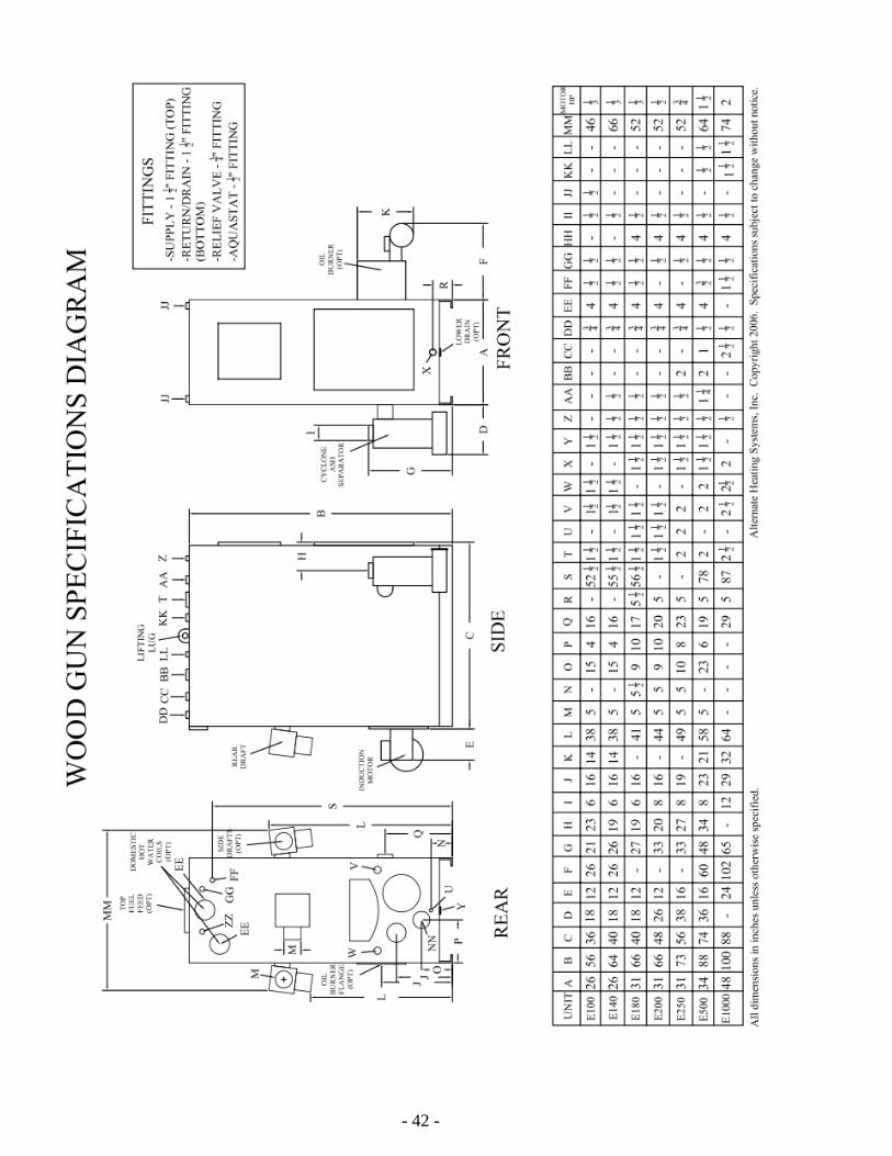
- 42 -

- 43 -
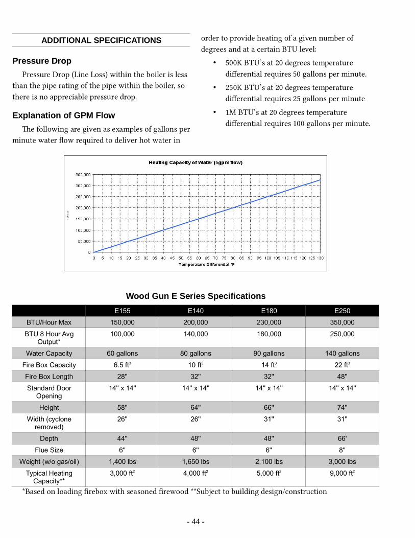
ADDITIONAL SPECIFICATIONS
Pressure DropPressure Drop (Line Loss) within the boiler is less
than the pipe rating of the pipe within the boiler, so there is no appreciable pressure drop.
Explanation of GPM Flowe following are given as examples of gallons per
minute water flow required to deliver hot water in
order to provide heating of a given number of degrees and at a certain BTU level:
• 500K BTU’s at 20 degrees temperature differential requires 50 gallons per minute.
• 250K BTU’s at 20 degrees temperature differential requires 25 gallons per minute
• 1M BTU’s at 20 degrees temperature differential requires 100 gallons per minute.
Wood Gun E Series SpecificationsE155 E140 E180 E250
BTU/Hour Max 150,000 200,000 230,000 350,000
BTU 8 Hour AvgOutput*
100,000 140,000 180,000 250,000
Water Capacity 60 gallons 80 gallons 90 gallons 140 gallons
Fire Box Capacity 6.5 ft3 10 ft3 14 ft3 22 ft3
Fire Box Length 28'' 32'' 32'' 48''
Standard DoorOpening
14'' x 14'' 14'' x 14'' 14'' x 14'' 14'' x 14''
Height 58'' 64'' 66'' 74''
Width (cycloneremoved)
26'' 26'' 31'' 31''
Depth 44'' 48'' 48'' 66'
Flue Size 6'' 6'' 6'' 8''
Weight (w/o gas/oil) 1,400 lbs 1,650 lbs 2,100 lbs 3,000 lbs
Typical HeatingCapacity**
3,000 ft2 4,000 ft2 5,000 ft2 9,000 ft2
*Based on loading firebox with seasoned firewood **Subject to building design/construction
- 44 -

Appendix B: Wiring Diagrams
- 45 -

- 46 -

Appendix C: Exploded Parts Drawings
- 47 -
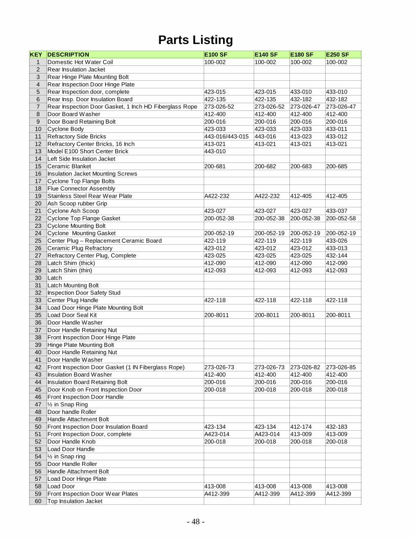
Parts Listing
- 48 -
KEY DESCRIPTION E100 SF E140 SF E180 SF E250 SF1 Domestic Hot Water Coil 100-002 100-002 100-002 100-0022 Rear Insulation Jacket3 Rear Hinge Plate Mounting Bolt4 Rear Inspection Door Hinge Plate5 Rear Inspection door, complete 423-015 423-015 433-010 433-0106 Rear Insp. Door Insulation Board 422-135 422-135 432-182 432-1827 Rear Inspection Door Gasket, 1 Inch HD Fiberglass Rope 273-026-52 273-026-52 273-026-47 273-026-478 Door Board Washer 412-400 412-400 412-400 412-4009 Door Board Retaining Bolt 200-016 200-016 200-016 200-01610 Cyclone Body 423-033 423-033 423-033 433-01111 Refractory Side Bricks 443-016/443-015 443-016 413-023 433-01212 Refractory Center Bricks, 16 Inch 413-021 413-021 413-021 413-02113 Model E100 Short Center Brick 443-01014 Left Side Insulation Jacket15 Ceramic Blanket 200-681 200-682 200-683 200-68516 Insulation Jacket Mounting Screws17 Cyclone Top Flange Bolts18 Flue Connector Assembly19 Stainless Steel Rear Wear Plate A422-232 A422-232 412-405 412-40520 Ash Scoop rubber Grip21 Cyclone Ash Scoop 423-027 423-027 423-027 433-03722 Cyclone Top Flange Gasket 200-052-38 200-052-38 200-052-38 200-052-5823 Cyclone Mounting Bolt24 Cyclone Mounting Gasket 200-052-19 200-052-19 200-052-19 200-052-1925 Center Plug – Replacement Ceramic Board 422-119 422-119 422-119 433-02626 Ceramic Plug Refractory 423-012 423-012 423-012 433-01327 Refractory Center Plug, Complete 423-025 423-025 423-025 432-14428 Latch Shim (thick) 412-090 412-090 412-090 412-09029 Latch Shim (thin) 412-093 412-093 412-093 412-09330 Latch31 Latch Mounting Bolt32 Inspection Door Safety Stud33 Center Plug Handle 422-118 422-118 422-118 422-11834 Load Door Hinge Plate Mounting Bolt35 Load Door Seal Kit 200-8011 200-8011 200-8011 200-801136 Door Handle Washer37 Door Handle Retaining Nut38 Front Inspection Door Hinge Plate39 Hinge Plate Mounting Bolt40 Door Handle Retaining Nut41 Door Handle Washer42 Front Inspection Door Gasket (1 IN Fiberglass Rope) 273-026-73 273-026-73 273-026-82 273-026-8543 Insulation Board Washer 412-400 412-400 412-400 412-40044 Insulation Board Retaining Bolt 200-016 200-016 200-016 200-01645 Door Knob on Front Inspection Door 200-018 200-018 200-018 200-01846 Front Inspection Door Handle47 ½ in Snap Ring48 Door handle Roller49 Handle Attachment Bolt50 Front Inspection Door Insulation Board 423-134 423-134 412-174 432-18351 Front Inspection Door, complete A423-014 A423-014 413-009 413-00952 Door Handle Knob 200-018 200-018 200-018 200-01853 Load Door Handle54 ½ in Snap ring55 Door Handle Roller56 Handle Attachment Bolt57 Load Door Hinge Plate58 Load Door 413-008 413-008 413-008 413-00859 Front Inspection Door Wear Plates A412-399 A412-399 A412-399 A412-39960 Top Insulation Jacket

- 49 -
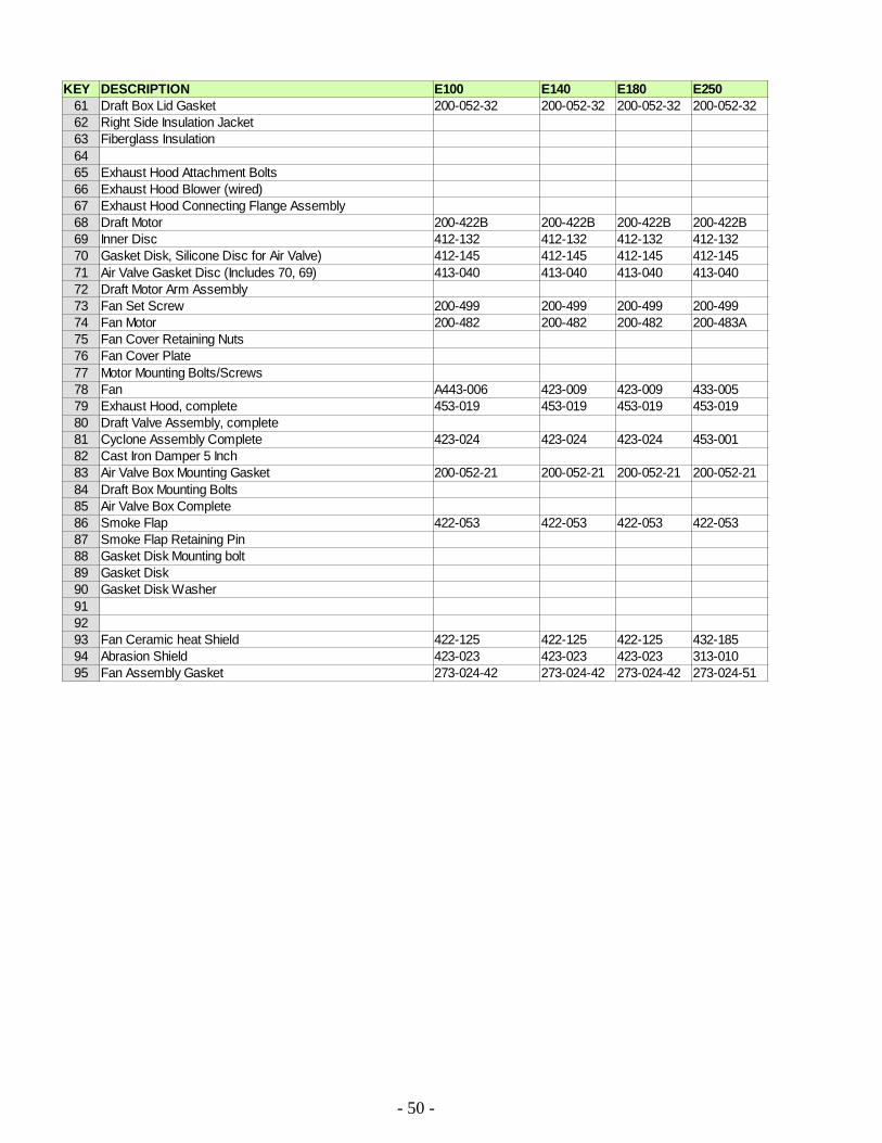
- 50 -
KEY DESCRIPTION E100 E140 E180 E25061 Draft Box Lid Gasket 200-052-32 200-052-32 200-052-32 200-052-3262 Right Side Insulation Jacket63 Fiberglass Insulation6465 Exhaust Hood Attachment Bolts66 Exhaust Hood Blower (wired)67 Exhaust Hood Connecting Flange Assembly68 Draft Motor 200-422B 200-422B 200-422B 200-422B69 Inner Disc 412-132 412-132 412-132 412-13270 Gasket Disk, Silicone Disc for Air Valve) 412-145 412-145 412-145 412-14571 Air Valve Gasket Disc (Includes 70, 69) 413-040 413-040 413-040 413-04072 Draft Motor Arm Assembly73 Fan Set Screw 200-499 200-499 200-499 200-49974 Fan Motor 200-482 200-482 200-482 200-483A75 Fan Cover Retaining Nuts76 Fan Cover Plate77 Motor Mounting Bolts/Screws78 Fan A443-006 423-009 423-009 433-00579 Exhaust Hood, complete 453-019 453-019 453-019 453-01980 Draft Valve Assembly, complete81 Cyclone Assembly Complete 423-024 423-024 423-024 453-00182 Cast Iron Damper 5 Inch83 Air Valve Box Mounting Gasket 200-052-21 200-052-21 200-052-21 200-052-2184 Draft Box Mounting Bolts85 Air Valve Box Complete86 Smoke Flap 422-053 422-053 422-053 422-05387 Smoke Flap Retaining Pin88 Gasket Disk Mounting bolt89 Gasket Disk90 Gasket Disk Washer919293 Fan Ceramic heat Shield 422-125 422-125 422-125 432-18594 Abrasion Shield 423-023 423-023 423-023 313-01095 Fan Assembly Gasket 273-024-42 273-024-42 273-024-42 273-024-51

Appendix D: Troubleshooting Guideis guide is intended to help you diagnose and repair basic problems with you boiler. If you believe your
problem is serious or the problem persists aer following all the procedures specified in this guide, contact AHS for support.
Problem Possible Cause Solution1. Boiler overheating a) Control malfunction
b) Incorrect control settingc) Intake air valve not closing properlyd) Excessive chimney drafte) Load door not sealing properly
a) Replace malfunctioning controlb) Adjust control settingc) Replace gasket or adjust linkaged) Reduce draft or see e)e) Adjust load door for proper seal,
replace gasket if necessary
2. Back-puffing (Also see section on Charging Boiler with Wood and the Back-Puffing Checklist)
a) Burn cycle too long/Too much wood b) Wood too small and/or excessively
dryc) Improper loading of fire boxd) Improper starting of wood
a) Fill with less wood to shorten burn cycle
b) Load larger fuel with higher moisturecontent
c) Follow proper loading procedured) Follow proper starting procedure so
as to attain high refractory temperatures
3. Smoke visible at stack a) Refractory not hot enoughb) Refractory not properly sealed in
fuel chamberc) Center cleanout plug not properly
sealedd) Leaking load doore) Leaking air valvef) Ash or charcoal buildup on or in
refractory
a) Allow refractory to come up to operating temperature; refer to instructions for building a fire
b) Seal refractory with “Trowleze” refractory cement.
c) Replace damaged ceramic pad at center cleanout plug
d) Check doors for airtight seale) Repair/replace air valve gasket discf) Clean ash from boiler. See “weekly
maintenance routine”
4. Fire goes out a) Boiler not cycling frequently enough (refractory cools to below kindling temperature)
b) Wood bridging in fuel chamber
a) Increase heat load or install draft cycle timer (contact AHS)
b) Reposition wood (always load wood length-wise front to back in chamber)
5. Smoke leakage at doors a) Improper gasket sealb) Door not tight enough, or is out of
adjustment
a) Repair seal with high temperature RTV sealant added at low point on door gasket
b) Adjust door
6. Fan vibration a) Bearing or motor looseb) Fan out of balancec) Creosote buildup in area of fan
impeller
a) Tighten all boltsb) Inspect fan for damagec) Raise return water temperatures or
use drier wood
7. Excessive water in the cyclone drawer (Also see condensation checklist)
a) The stack temperature may not be high enough.b) The fire box is being filled too full for the heat demand.c) There may be a blockage in the flue,cyclone, heat exchanger, or refractory.d) The wood logs are too large and/or has high moisture content.e) Load door seal or air valve seal is leaking
a) The boiler should be in an insulated room. The flue stack needs to be insulated (If the room is typically cold.)
b) Fill the fire box only half full or enough to burn for eight hours or less (shorten cycles).
c) Remove ash from fire box and refractory. Clean the heat exchanger, cyclone, or flue.
- 51 -

f) The boiler water temperature is too low or Water temperature difference between supply and return may be more than 20ºF
d) Burn smaller wood, split wood, and/or dryer wood. Build a hotter fire. Remember that more wood does not always equate to more heat.
e) Adjust and/or replace load door seal and/or Air Valve
f) Raise the boiler operating temperature, (Max 200º F)
8. The boiler burns more wood than usual
a) The wood has a higher moisture content level than normal.
b) The wood is dry but has less weight per piece of wood (soft wood).
c) The heat exchanger needs cleaned.
a) Try burning drier wood.b) Try burning hard wood.c) Clean the heat exchanger.
9. The pressure relief valve is releasing(Boiler pressure keeps rising)
a) Pressure reducing valve is malfunctioning.
b) There is not enough expansion capacity.
c) The domestic coil is leaking.
a) Replace pressure reducing valve. b) Add an expansion tank or replace a
malfunctioning one. c) Replace or isolate the domestic coil.
10. There is smoke or creosote leakingout of air inlet connection. (Pre-2014 Boilers)
a) The air valve assembly has been moved of knocked out of position.
a) Reposition and tighten the air valve and reseal the sleeve where enters the boiler. Be careful not to knock the air valve out of position when loading fuel into the boiler.
11. There is excessive creosote buildup on boiler vessel located behindthe lower front inspection door area.
a) The fire box is being filled too full for the heat demand.
b) There may be a blockage in the flue,cyclone, heat exchanger, or refractory.
c) The wood logs are too small and/or have very low moisture content.
d) Load door seal or air valve seal is leaking.
e) The boiler is operated with water temperature too low. The stack temperature may not be high enough.
a) Fill the fire box only half full or enough to burn for eight hours.
b) Remove ash from fire box and refractory. Clean the heat exchanger, cyclone, or flue.
c) Burn larger wood, unsplit wood, and/or green wood.
d) Adjust load door, fix, or replace air valve.
e) Raise the boiler operating temperature to 180-190 F
12. Steel has etching or pitting a) Heating domestic water in the summer time with a carbon steel boiler.
a) Increase operating temperature in boiler. Only use small amounts of very dry wood to burn straight through the fuel charge with no cycling.
- 52 -

Index of Photos and Illustrations Cyclone Attachment.................................................7 Proper chimney connection....................................10 Stove pipe passing through wall.............................10 Pressure Relief Valve.............................................11 Pressure regulating valve and backflow prevention valve configuration.................................................11Three Mixing Valve: Return Water Protection.........12 Photo: Low Water Cutoff Installation.....................12 Plumbing – Coil in Series......................................14 Plumbing – Coil in Parallel....................................15Figure: Domestic Coil Tempering Valve.................15 Plumbing – Coil with circulator.............................15 E180, E250 Oil Burner..........................................16 E100, E140 Combustion Chamber.........................16Photo: (Smoke flap)................................................18 Photo: (Smoke flap installed).................................19 Automatic and Manual Dampers............................22 EPA Side Tunnel Plug............................................23 EPA Side Tunnel Plug Install.................................23Air Valve Gasket.....................................................31 Air Valve Motor Clamp Alignment........................32 Air Valve Disk in Open Positioning.......................32Door Hinge Plate Adjustment.................................33Door Latch Shims...................................................33 Load Door with Old Seal Removed and High Temperature Silicone..............................................33Load Door with Fiberglass Braid Tape....................33Load Door with Fiberglass Braid Tape and More High Temperature Silicone.....................................34Adding Preformed Silicone Bead to Door...............34 Marking to Trim....................................................34Trimming Preformed Silicone Bead........................34Adding High Temperature Silicone to Butt Joint of Trimmed Bead........................................................34
Finished Joint........................................................34Reinforcing Corners with High Temperature Silicone...............................................................................34 Finishing the Corners.............................................35 Finished, Level Bead.............................................35 Rear Inspection Door.............................................35 Front Inspection Door............................................36 Direct-drive fan attached to boiler..........................36...............................................................................36 Belt-drive fan assembly removed from boiler and showing white gasket..............................................36 Fan Assembly Mount Points..................................37 Mark Assembly Orientation...................................37Fan Hub Set Screws................................................37 One Inch Nut for Pulling Fan.................................38 Jaw Puller at the Ready..........................................38 AHS Fan Puller Tool..............................................38 AHS Fan Puller Tool at the Ready..........................38 Separate Heat Shield from Motor Mount Plate.......38 Closeup of Motor Mounting Bolts.........................38 Motor Frame Assembly Bolts................................39 Loosening Motor End Shield from Motor..............39 Lifting the End Shield with Armature....................39 Loosening Screws Securing Bearing to End Shield39 Jaw Puller at the Ready on Motor Bearing.............40AHS Bearing Puller................................................40 Steel Center Brick – 8 Inch....................................41 New Ceramic Blanket in Place...............................42 Positioning New Side Brick...................................43Wood Gun Air Inlet Ducting Installations...............64Wood Gun in Primary/Secondary System...............65Operating an Alternate Heating Systems Boiler in Tandem with Existing Boiler..................................66
- 53 -

Appendix F: Boiler Piping and Ducting Examples
- 54 -

Wood Gun Air Inlet Ducting Installations
- 55 -

Wood Gun in Primary/Secondary System
- 56 -
Note:
1. A call for heat from any zone activates Boiler Circulators, System Circulator and Zone Circulator.
2. Each Boiler Circulator is also controlled by a low limit to prevent operation when the Boiler is cold.
3. Dump zone operation will activate one or more zones, System Circulator and Boiler Circulator.
4. Do not bypass temperature supply control system on radiant heat system. In radiant heat applications, permit activation of a call for heat but allow system controls to regulate water temperature.
Not all system components, valves and devices are shown in this drawing. Actual conditions and application requirements will vary. Please consult a heating expert or your Alternate Heating Systems for additional information.

Operating an Alternate Heating Systems Boiler in Tandem with Existing Boiler
- 57 -
Note: The above illustrates one possible method of connecting the Wood GunTM with an existing boiler. This connection is as follows: using a small circulator (and with the backup boiler piped into the return tapping) run another pipe from the supply tapping T, of the Wood Gun™ to the supply line, of the existing boiler on the lower side of the flow control valve. A minimum of 1 in diameter pipe should be used for this connection on the model E100 – E140. The pipe size must be determined by taking into account the distance involved and flow required. The new circulator should be wired to the power for the Wood Gun. When power to the Wood Gun is on, the circulator should be running. An alternate option is to attach a strap on aquastat on the Wood Gun supply line that closes on temperature rise. This will automatically activate the pump at a given temperature. Overheat control (as pictured above) on the Wood Gun is optional

- 58 -
LIMITED WARRANTYWOOD GASIFICATION BOILERS: E155 SF E140 SF E180 SF E250 SF
The manufacturer, ALTERNATE HEATING SYSTEMS, warrants to the original owner, for the periods specified below, that the boiler to which this warranty applies is free from defects in materials and workmanship when installed, operated, and maintained in accordance with the printed instructions supplied with the unit.
A. WHAT IS COVERED AND FOR HOW LONG (all from date of original installation)1) VESSEL:
STAINLESS STEEL BOILER VESSEL, TWENTY (20) years pro-rated (pro-rated as follows: 1st to 10th year – full: 11th year – 40%: 12th year - 30%: 13th year – 20%: 14th year – 10%: 15th – 20th year – 10%). This does not cover any corrosion or deterioration in boiler vessel due to improper pH levels in water or oxidized water (heating systems that have plastic piping).
2) Doors (excluding gaskets, knobs, and ceramic insulation board), draft regulation mechanisms, insulation jacket, draft fan assembly (excluding ceramic heat shield), stack/cyclone assembly, firebox refractory side brick and center brick – ONE (1) year.3) All electrical and plumbing components and controls such as temperature/pressure gauge, safety relief valve, aqua stat controllers, electric motor, domestic hot water coil, oil burner, fan shaft bearings, timer, draft motor, etc. purchased by Alternate Heating Systems from other manufacturers are Limited to warranties offered by those manufacturers, typically One (1) year.4) V-belt, pulleys, ceramic board door and fan heat shields, ceramic blanket firebox lining, fasteners, sight glass, smoke flap, door gasket and silicone rubber seal, door handle knobs, paint, wiring, and wiring devices -Thirty (30) days.
B. WHAT WE WILL DO AND NOT DO1) Alternate Heating Systems will repair and replace, at our option, units or component parts found defective after inspection by Alternate Heating Systems or our authorized representative during the periods outlined above.2) Alternate Heating Systems SHALL NOT BE LIABLE UNDER THIS WARRANTY IF:
a) the unit or any of its component parts have been subject to misuse, alteration, unauthorized repair, neglect, accident, or damage from handling.b) the unit is not installed, operated and maintained in accordance with the printed instructions supplied with the unit and in accordance with local plumbing and/or building codes.c) the unit is operated above its rated output which is shown on the nameplate attached to the unit and listed in Alternate Heating System’s printed literature.d) the unit is fired with fuels other than those recommended by Alternate Heating Systems. This includes fuels recommended by dealers and distributors selling Alternate Heating Systems products if these are not fuels recommended by Alternate Heating Systems.
C. WHAT THE CUSTOMER MUST DO1) Contact the dealer who sold you the unit.2) If said dealer cannot be located, contact any other Alternate Heating Systems dealers in your area.3) If you are unable to locate a dealer, submit your warranty claim directly to Alternate Heating Systems at the address listed below.4) When you make an inquiry or warranty request, be sure to include the following information:
a) Unit model numberb) Serial numberc) Date of installationd) Dealer’s namee) Type of fuel burned
5) The OWNER and not Alternate Heating Systems or its dealers will be liable for the following costs involved in repair or replacement of the defective unit or component part
a) All necessary costs in returning the defective unit or component part to the factory or other location designated by Alternate Heating Systems.b) All freight and delivery costs of shipping a new or required unit or replacement component part to the owner.c) All labor and other costs incurred in the removal of the defective unit or part and installation of a new or required unit or part.d) Any material required to complete installation of new or required unit or replacement part.
D. LIMITATIONS AND STATE LAW RIGHTS1) Alternate Heating Systems neither assumes nor authorizes any representative or other person to assume for it any other obligation or liability in connection with its products other than expressly written here.2) Implied warranties of merchantability and fitness for a particular purpose are limited to the duration of this LIMITED WARRANTY.3) Alternate Heating Systems shall not be liable for any incidental or consequential damages such as water, smoke or heat damage to property arising directly or indirectly from any defect in its products or their use.4) Some states do not allow limitation on how long an implied warranty lasts and the exclusion or limitation of incidental or consequential damages, so the above limitations and exclusions may not apply to you.5) This warranty gives you specific legal rights. You may also have other rights, which vary from state to state.6) The remedies set forth herein shall be the exclusive remedies available to the owner.
ALTERNATE HEATING SYSTEMS2393 Little Egypt Rd
Harrisonville, PA 17228
IMPORTANT: READ AND KEEP IN YOUR POSSESSION!