installation and operation manual for reference only · installation and operation manual 4024 epg...
TRANSCRIPT

Installation and Operation Manual
4024 EPG (Electrically Powered Governor)
24 V, 4 ft-lb (5.4 J) System Isochronous with Start Fuel Limit
Manual 82042A
INA
CTI
VE–f
or re
fere
nce
only
The information in this publication is no longer current, and may not reflect changes or safety issues that have occurred since the publication was originally released.

WARNING Read this entire manual and all other publications pertaining to the work to be performed before installing, operating, or servicing this equipment. Practice all plant and safety instructions and precautions. Failure to follow instructions can cause personal injury and/or property damage. The engine, turbine, or other type of prime mover should be equipped with an overspeed shutdown device to protect against runaway or damage to the prime mover with possible personal injury, loss of life, or property damage. The overspeed shutdown device must be totally independent of the prime mover control system. An overtemperature or overpressure shutdown device may also be needed for safety, as appropriate.
CAUTION To prevent damage to a control system that uses an alternator or battery-charging device, make sure the charging device is turned off before disconnecting the battery from the system. Electronic controls contain static-sensitive parts. Observe the following precautions to prevent damage to these parts. • Discharge body static before handling the control (with power to the control
turned off, contact a grounded surface and maintain contact while handling the control).
• Avoid all plastic, vinyl, and Styrofoam (except antistatic versions) around printed circuit boards.
• Do not touch the components or conductors on a printed circuit board with your hands or with conductive devices.
IMPORTANT DEFINITIONS WARNING—indicates a potentially hazardous situation which, if not avoided, could result in death or serious injury. CAUTION—indicates a potentially hazardous situation which, if not avoided, could result in damage to equipment. NOTE—provides other helpful information that does not fall under the warning or caution categories.
Woodward Governor Company reserves the right to update any portion of this publication at any time. Information provided by Woodward Governor Company is believed to be correct and reliable. However, no responsibility is assumed by Woodward Governor Company unless otherwise expressly undertaken.
© Woodward 1990 All Rights Reserved
INA
CTI
VE–f
or re
fere
nce
only

Manual 82042 4024 EPG
Woodward i
Contents
CHAPTER 1. GENERAL INFORMATION........................................................... 1 Description..............................................................................................................1 Customer Supplied Return Spring..........................................................................3 Accessories ............................................................................................................3 CHAPTER 2. INSTALLATION.......................................................................... 4 Speed Control Installation ......................................................................................4 Actuator Mounting and Linkage..............................................................................4 Magnetic Pickup .....................................................................................................6 Wiring Instructions ..................................................................................................7 CHAPTER 3. CALIBRATION......................................................................... 12 Introduction...........................................................................................................12 Signal Generator ..................................................................................................12 Installation Checks ...............................................................................................12 Initial Pre-Start Settings........................................................................................13 Start Up Adjustments............................................................................................14 Adjust for Stable Operation ..................................................................................14 Dynamic Adjustment.............................................................................................15 Start Fuel Limit .....................................................................................................15 CHAPTER 4. DESCRIPTION OF OPERATION................................................. 17 Electronic Circuits.................................................................................................17 Speed Control.......................................................................................................17 Actuator Position Signal .......................................................................................17 Stability and Gain .................................................................................................17 Start Fuel Limit .....................................................................................................18 Failed Speed Sensor ............................................................................................18 Auxiliary Input .......................................................................................................18 Ramp Generator...................................................................................................18 Speed Trim ...........................................................................................................19 Actuator ................................................................................................................19 CHAPTER 5. TROUBLESHOOTING............................................................... 22 CHAPTER 6. SERVICE OPTIONS ................................................................. 24 Product Service Options.......................................................................................24 Returning Equipment for Repair...........................................................................25 Replacement Parts ...............................................................................................26 How to Contact Woodward...................................................................................26 Engineering Services ...........................................................................................27 Technical Assistance............................................................................................28
INA
CTI
VE–f
or re
fere
nce
only

4024 EPG Manual 82042
ii Woodward
Illustrations and Tables Figure 1-1. Frequency Range Switch.....................................................................2 Figure 2-1. Linear Linkage .....................................................................................5 Figure 2-2. Carburetor Compensating Linkage......................................................5 Figure 2-3. Wiring Direct from Battery to Control ...................................................8 Figure 2-4. EPG Speed Control Outline .................................................................9 Figure 2-5. 4024 Actuator Outline Drawing..........................................................10 Figure 2-6. Plant Wiring Diagram and Shield Grounding.....................................11 Figure 3-1. Diesel Engine Response Curves .......................................................16 Figure 4-1. Block Diagram of Electronics.............................................................20 Figure 4-2. Schematic of 4024 Actuator...............................................................21
INA
CTI
VE–f
or re
fere
nce
only

Manual 82042 4024 EPG
Woodward 1
Chapter 1. General Information
Description The 4024 EPG (electrically power governor) system provides up to 4 ft-lb (5.4 J) of work to move the fuel setting of diesel or spark ignited engines. Engines with mechanical loads and generator loads are handled equally well. Generator sets which will be paralleled, however, require additional current and potential transformers and the EPG Load Sensor. Installation of the actuator is simple because it does not require a hydraulic supply or mechanical governor drive. Power Requirement Most EPG systems use the same battery power as the engine installation (24 Vdc). If the engine does not have an auxiliary 24 Vdc battery system, one must be provided for the governor. Maximum steady state current is 10 A. Return Spring The actuator provides torque only in the increased fuel direction. A return spring is required to move toward minimum fuel. Most actuators will have the return spring installed at the factory. Actuators ordered without a return spring will require the installation of a spring conforming to the specified rate and preload. Speed Control An EPG is a three-component system. A magnetic pickup, speed control, and actuator are all required. Speed controls are available for 24 volt systems with best performance between 3000 and 6000 Hz gear tooth speed. The speed being sensed will be the number of teeth in the gear being sensed times the rpm divided by 60.
60rpm x teeth of No.=Hz
INA
CTI
VE–f
or re
fere
nce
only

4024 EPG Manual 82042
2 Woodward
Switch
Positions 750–1500 1500–3000 3000–6000 6000–12
000 7500–15
000 ONE OFF ON ON ON ON TWO OFF OFF ON ON ON
THREE OFF OFF OFF ON ON FOUR OFF OFF OFF OFF ON
P/N PREFIX A B No prefix C D
Figure 1-1. Frequency Range Switch
Response of the controls is different for diesel and gas turbine applications than for gasoline and gas fueled engines. 8290-147 control boxes provide the correct response for spark ignition gas or gasoline powered engines. 8290-148 control boxes provide the correct response for diesel engines or gas turbines. Different Actuators Three different actuators are available for use with the selected EPG control system: • Clockwise output shaft with return spring on the counterclockwise end,
8256-060. • Counterclockwise output shaft with return spring on the clockwise end,
8256-080. • Both clockwise and counterclockwise shaft open, with a customer supplied
return spring, conforming to rate and preload requirements, to be installed at the time of installation, 8256-081.
The clock-spring type of return spring provided by Woodward on EPG models will provide about 3.5 ft-lb (4.7 J) of work in the decrease fuel direction. (Torque equals 0.8 lb-ft [1.1 N m] at minimum fuel and 8 lb-ft [10.8 N m] at maximum fuel.) The actuator will provide about 4 ft-lb (5.4 J) of work in the increase fuel direction in addition to the work needed to overcome the return spring. (Torque equals 9 lb-ft [12.2 N m] at the 5° minimum fuel and 3 lb-ft [4.1 N m] at the 35° position.) 4024 EPG systems with position feedback from the actuator are described in manual 04149.
INA
CTI
VE–f
or re
fere
nce
only

Manual 82042 4024 EPG
Woodward 3
Customer Supplied Return Spring If a spring is installed it must provide a rate of 2.125 lb-in (0.24 N m) of torque per degree of actuator movement (±10% measured at the actuator terminal shaft). The preload at minimum fuel must be 10 lb-in (1.1 N m) (±10% measured at the actuator terminal shaft). Start Fuel Limit The 4024 EPG provides an adjustable start fuel limit. This limit sets the maximum actuator drive current and likewise an approximate maximum fuel setting. The limit goes into place when the magnetic pickup frequency drops below a failed signal point. It remains in place until the speed increases to 94% of rated. The start fuel limit can be removed by adjusting it to a speed in excess of rated speed.
Accessories To Parallel a Generator Add the EPG Load Sensor to the EPG in paralleled generator application. Woodward makes many accessories for paralleled generator applications. To Decrease Acceleration and Deceleration Rates The Ramp Generator, or an optional external capacitor, can be used to increase the time to go from idle to rated speeds and vice versa. The Ramp Generator provides a linear ramp with time adjustable to 25 seconds in a typical case. It is useful in smoke limiting application. Use part number 8271-909 with the 4024 EPG system. The addition of a capacitor provides an exponential ramp with times up to four seconds. Exponential means it changes speed rapidly at first, but slows as it reaches its final value. Using a capacitor provides about one second of ramp time per 50 microfarad, 200 microfarad maximum. See the typical wiring diagram for capacitor requirements.
INA
CTI
VE–f
or re
fere
nce
only

4024 EPG Manual 82042
4 Woodward
Chapter 2. Installation
Speed Control Installation The speed control is designed to operate within a temperature range of –40 to +75 °C (–40 to +167 °F). Install the control box in a location with space for adjustment and wiring access. Do not expose the control to sources of radiant heat, such as exhaust manifolds or turbochargers. Choose a protected location so the control won't be damaged when moving the prime mover or when near-by equipment is moving. Mount the control close enough to the actuator and battery to meet the wire-length requirements. (See wiring instructions in this chapter.) The control will generate a little heat and surfaces must be open to normal air movement. No special ventilation is required. Ideally the control should be mounted flush to the metal side of a control cabinet, protected from the weather and high humidity, and close to the engine being controlled. The location should provide protection from high-voltage or high-current devices, or devices which produce electro-magnetic interference. After initial adjustments are completed all functions may be selected with remote switches on the control panel. Ready access to the control will not be required for normal engine operation. Do not install the control box directly on the engine. Use the control for a template for the installation screws, or use the outline drawing in this chapter of the manual. Shield Ground Review the plant wiring diagrams in this manual and prepare to ground the shields at the control. One of the installation screws is normally used for the shield ground terminal.
Actuator Mounting and Linkage Proper design and installation of the linkage from the actuator to the engine is necessary if the unit is to give good control. Most installations have the actuator directly controlling the fuel flow to the engine or turbine, by moving either the fuel valve, butterfly valve, or fuel rack. Some installations have the actuator controlling the speed-setting shaft on a mechanical governor. This type of installation can give adequate control for generator sets, but may not provide control from full load to idle or shutdown. The linkage is often connected to the shutdown lever or shaft. When this type of installation is used, the mechanical governor functions as a high-speed limit. Note that when the shutdown lever is selected for control, the emergency and safety shutdown features are often disconnected.
INA
CTI
VE–f
or re
fere
nce
only

Manual 82042 4024 EPG
Woodward 5
WARNING Be prepared to make an emergency shutdown when starting the engine, turbine, or other type of prime mover, to protect against runaway or overspeed with possible personal injury, loss of life, or property damage. Linkage should be designed to provide a linear relationship between actuator movement and power from the prime mover. Most diesel engines are linear, and in this case a movement of about 4 degrees of actuator-shaft position (10% of the total movement available) should cause about a 10–15% change in the position of the fuel control shaft and the power output of the engine. Figure 2-1 shows this type of linkage between the actuator and fuel control level. (See Figure 2-5 for additional information on actuator travel.)
Figure 2-1. Linear Linkage
Figure 2-2. Carburetor Compensating Linkage
Carburetors and some diesel engines have non-linear fuel controls. In these cases the actuator must be linked to the engine as shown in Figure 2-2. This compensating linkage requires more actuator movement to make a change in fuel at minimum fuel than at maximum fuel. The power output must remain linear with either type of linkage. Study the control features of the engine being fitted with the 4024 control to determine the type of linkage required. Contact Woodward Governor Company for additional linkage information. Incorrect matching of the actuator output and fuel-setting lever is the most common cause of unstable operation, and can cause stable operation at some fuel setting but oscillation at other fuel settings. Manually stroke the fuel-control linkage from stop to stop, as if the actuator were moving it. The linkage must move freely, without friction, and without backlash. Lubricate or replace worn linkage or fuel control parts as required. If a return spring is not included on the actuator a return spring must be attached to the system. The return spring may operate on the terminal lever of the actuator or directly on the engine linkage.
WARNING It is important that the return spring be able to shutdown the engine or turbine. The actuator has no power in the shut down direction and should the return spring be too weak, or should the return spring come off or break, the actuator will not be able to reduce engine speed. Resulting overspeeds can destroy equipment, cause personal injury, or even loss of life.
INA
CTI
VE–f
or re
fere
nce
only

4024 EPG Manual 82042
6 Woodward
Make sure the actuator is capable of moving the fuel control to maximum and minimum limits. Let the fuel control limit actuator travel. Set the linkage so the actuator is just above minimum when the fuel control is at its minimum stop and so the actuator is just below maximum when the fuel control is at its maximum stop. (Some fuel systems will bind if the stops are reached. In these cases it is possible to use the maximum and minimum stops of the actuator. This will require a more precise final adjustment of the control-rod length.) Using too little actuator rotation can cause control instability and other control problems. Too little actuator rotation will also limit the amount of droop which can be adjusted into the control system (Droop is available with the load sensor.) If it is necessary to use less than the recommended rotation adjust the linkage so the actuator approaches or reaches the maximum position at maximum fuel. Use good rod-end connectors with as little slack as possible. Select rod ends which will not become loose and which will wear well during the nearly constant movement associated with precise speed control. Low friction, long wearing rod ends are available from Woodward. The link connecting the actuator lever to the fuel-control lever must not be so long that if flexes when the prime mover is running. In most cases a piece of threaded rod is used for the link. Assemble the rod end and rod with jam nuts at both ends. A rod end will have to be removed from either the actuator or engine end to change the length of the rod. However, this is usually preferred over the use of a turn-buckle type of rod with left- and right-hand screws because it prevents accidental speed changes should the jam nuts work loose and because it allows both rod ends to have more common right-hand threads. If a long connecting rod between the actuator and the engine fuel control is required, use a hollow tube to reduce weight while maintaining strength. The hollow tube will usually be less subject to vibration that will a solid connecting rod. Actuator levers are available from Woodward which allow adjustment of the rod-end location in respect to the center of the actuator shaft. The lever used must have a 0.500 inch -36 serration to fit on the actuator. Adjust the location of the rod end on the lever to achieve the desired rotation of the actuator shaft between minimum and maximum positions. (Use as much of the 42 degrees rotation as possible, not less than 25 degrees). To increase the amount of rotation, move the rod end closer to the actuator shaft. To decrease the amount of rotation used, move the rod end farther away from the actuator shaft. If less than 42 degrees actuator rotation is necessary, maintain about half of the unused travel at the minimum fuel direction and half of the unused travel at the maximum fuel direction. Using less than the recommended amount of rotation will often cause instability in the governor system.
Magnetic Pickup Install the magnetic pickup to work with the selected gear through a housing or rigid bracket. Make sure the sensed gear is of magnetic material. Set the gap between the gear and the end of the magnetic pickup according to instructions which accompany the pickup. Magnetic pickups of various sizes are available from Woodward.
INA
CTI
VE–f
or re
fere
nce
only

Manual 82042 4024 EPG
Woodward 7
The standard models of magnetic pickups require mating connectors, MS 3102R-18-eP. The connectors can be furnished with the magnetic pickup ordered from Woodward. Manual 82510, Magnetic Pickups and Proximity Switches for Electric Controls, contains detailed information on the installation of the sensing device.
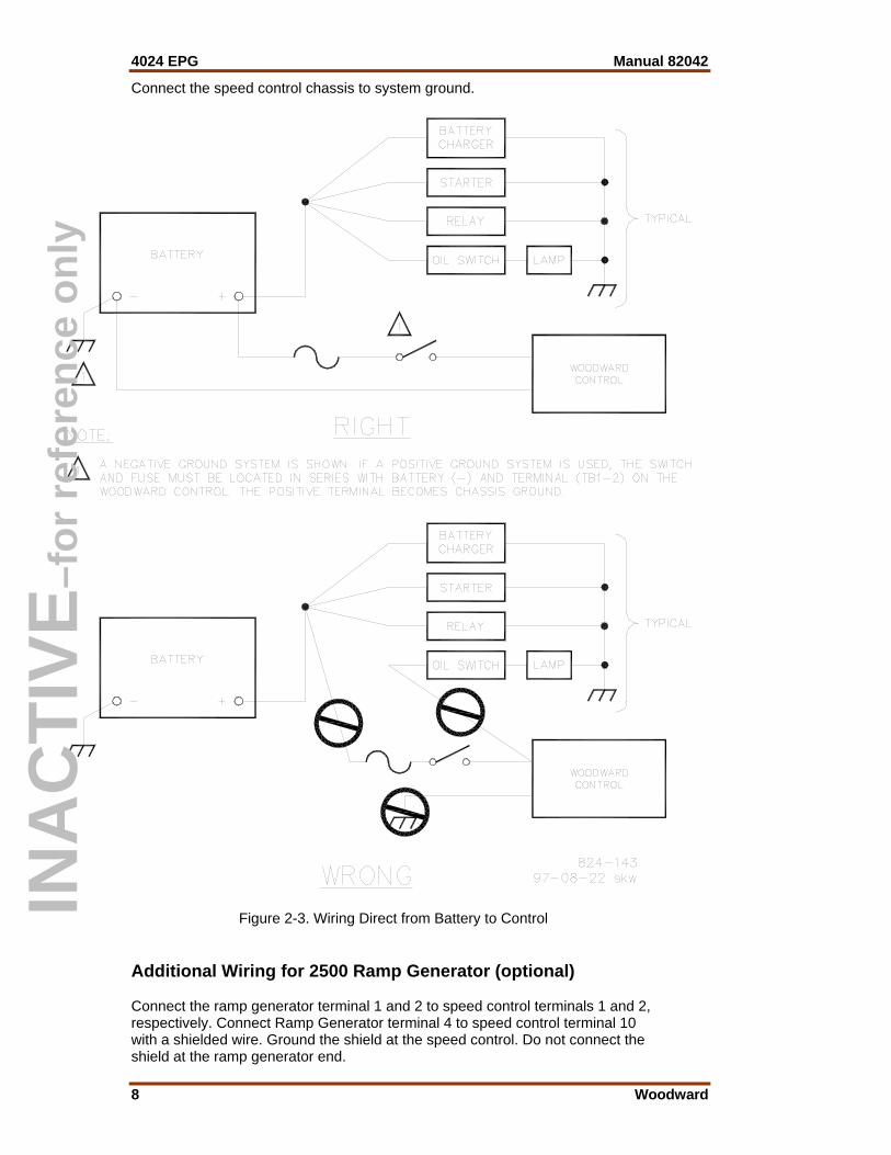
Wiring Instructions External wiring connections and shielding requirements for a typical control installation are shown in the plant wiring diagram (Figure 2-6). These wiring connections and shielding requirements are explained in the balance of this chapter. Electromagnetic interference (EMI) is the undesirable interaction of electronic circuits with each other and sometimes with themselves. Woodward has established procedures to prevent most EMI which will affect prime-mover-control circuits. Following these procedures is a slight extra effort in planning and installing electronic governing systems, but is valuable insurance over the life of the plant. Follow all of the shielding instructions to assure maximum efficiency and dependability of the electronic governing system. Application note 50532, EMI Control for Electronic Governing Systems, has additional information on EMI causes and prevention. Shielded Wiring All shielded cable must be twisted conductor pairs. Do not attempt to tin the braided shield. All signal lines should be shielded to prevent picking up stray signals from adjacent equipment. Connect the shields to the control case as shown in Figure 2-6, the plant wiring diagram. Wire exposed beyond the shield should be as short as possible, not exceeding six inches. The other end of the shields must be left open and insulated from any other conductor. Do not run shielded signal wires with high voltage or high current wires. When passing shields through connectors and terminal blocks, treat each shield as if it were a signal wire. Each shield must be given its own pin or terminal and kept insulated from nearby wires and metal conductors. Do not tin (solder) braided shields. Use 14 AWG (2.0 mm²) or 12 AWG (3.0 mm²) wire throughout the EPG circuit. The total distance from the battery to the control and from the control to the actuator must not exceed 8 feet (2.4 m) if 14 AWG wire is used or 22 feet (6.7 m) if 12 AWG wire is used. The 8 foot limit for 14 AWG wire will make it difficult to wire most installations, and 12 AWG wire should always be used, if possible. The fuse and switch or circuit breaker must be in the non-grounded battery lead. Use a 15 A fuse and switch for the installation. Starter relays make good EPG power switches. The battery connection to speed control terminals 1 and 2 must be directly from the terminals, not through distribution points.
CAUTION Connect power wires directly to the battery terminals. The speed control can be damaged if these wires are connected to distribution points.
INA
CTI
VE–f
or re
fere
nce
only
4024 EPG Manual 82042
8 Woodward
Connect the speed control chassis to system ground.
Figure 2-3. Wiring Direct from Battery to Control
Additional Wiring for 2500 Ramp Generator (optional) Connect the ramp generator terminal 1 and 2 to speed control terminals 1 and 2, respectively. Connect Ramp Generator terminal 4 to speed control terminal 10 with a shielded wire. Ground the shield at the speed control. Do not connect the shield at the ramp generator end.
INA
CTI
VE–f
or re
fere
nce
only

Manual 82042 4024 EPG
Woodward 9
Additional Wiring for EPG Load Sensor (optional) Mount the Load Sensor where it will be between –40 and +71 °C (–40 and +160 °F). Do not mount it on the prime mover. The best location is usually the switchgear cabinet which has the CTs and PTs. Wire the Load Sensor as shown in the diagram for additional wiring. Careful attention to correct CT and PT wiring can save time during the phasing checks later on. Install appropriate voltage selection jumpers at terminals 17 through 20. Refer to Manual 82313 for Load Sensor information.
Figure 2-4. EPG Speed Control Outline
INA
CTI
VE–f
or re
fere
nce
only

4024 EPG Manual 82042
10 Woodward
1. Electrical Characteristics Resistance 1.4 ±0.14 Ω at 20 °C Inductance 45 mH at 500 Hz Current 7 A maximum continuous 2. Stroke 42° ±1° 3. Nominal Return Spring Torque Actuator at 0° 10 lb-in (1.1 N m) Actuator at 42° 100 lb-in (11.3 N m) 4. Minimum Output Torque Current Position Torque 4 A 5 degrees 25 lb-in (2.8 N m) 6 A 5 degrees 50 lb-in (5.6 N m) 6 A 35 degrees 5 lb-in (0.6 N m) 8 A 5 degrees 80 lb-in (9.0 N m) 8 A 35 degrees 30 lb-in (3.4 N m) 10 A 5 degrees 110 lb-in (12.4 N m) 10 A 35 degrees 40 lb-in (4.5 N m) 5. Nominal No-load Performance Current Position 1.0 A 0 degrees 4.0 A 21 degrees 6.0 A 42 degrees 6. Environment Operating Temperature –30 to +212 °F (–34 to +100 °C) Storage Temperature –40 to +240 °F (–40 to +115 °C) Vibration US MIL-STD-810C, Curve T, 30 G Shock US MIL-STD-901C, 400 lb hammer
Figure 2-5. 4024 Actuator Outline Drawing (shown with return spring on CW output)
INA
CTI
VE–f
or re
fere
nce
only

Manual 82042 4024 EPG
Woodward 11
Figure 2-6. Plant Wiring Diagram and Shield Grounding
INA
CTI
VE–f
or re
fere
nce
only

4024 EPG Manual 82042
12 Woodward
Chapter 3. Calibration
Introduction Initial calibration and troubleshooting of the EPG are identical. Many of the settings are interrelated and for this reason if trouble is experienced the best procedure is to follow the initial installation routine completely to see if the problem is cured by adjustment of the system.
Signal Generator A signal generator to simulate the output of the MPU will make setup or troubleshooting of the electronic control system easier and safer since it will allow the technician to set idle and rated speeds and check all wiring without running the engine. The wave form can be sine, square, or triangular. The signal generator must be capable of generating the frequency of the control system, not the rpm of the engine. The frequency will be the number of teeth on the sensed gear times the desired rpm divided by 60.
60rpm x teeth of No.=Hz
If a signal generator is not available, all checks can be made with the engine, but overspeeds are possible.
WARNING Be prepared to make an emergency shutdown when starting the engine, turbine, or other type of prime mover, to protect against runaway or overspeed with possible personal injury, loss of life, or property damage.
Installation Checks Perform the checks in the order indicated. Terminal numbers in this chapter refer to the speed control. 1. Check that all electrical connections are correctly made and terminal screws
tightened, the magnetic pickup is properly installed and the jam nut tightened, and the actuator and linkage are securely fastened.
2. Do not start the engine now. Turn on governor power. Check the battery
voltage at terminals 1 (+) and 2 (–). It must be from 18 to 32 Vdc for 4024 controls.
3. If a signal generator is available: Attach the output to terminals 5 and 6,
leaving the MPU connections off. Set the signal-generator output between 2 and 10 Vrms. If a signal generator is not available proceed to step 6.
INA
CTI
VE–f
or re
fere
nce
only

Manual 82042 4024 EPG
Woodward 13
4. Set the signal-generator frequency to about half of idle speed. Close the idle/rated switch. Turn the signal generator and governor power on. The actuator must move to maximum-fuel position (Start Fuel Limit fully clockwise).
5. Set the signal generator for MPU frequency at rated speed. Close the
idle/rated switch. Set the external speed trim pot (if used) at mid position. Observe the linkage position.
a. If the linkage is at max-fuel position slowly turn the rated-speed
potentiometer counterclockwise until the linkage just begins to move to min-fuel.
b. If the linkage is at min-fuel position slowly turn the rated-speed
potentiometer clockwise until the linkage just begins to move to max-fuel.
Continue to very slowly adjust the rated-speed pot, trying to stop the linkage between the minimum- and maximum-fuel stops. Stop adjusting when the linkage moves slowly. It will not be possible to stop the motion. The rated-speed reference is now set very close to desired speed. If a signal generator is not available, turn the rated speed pot fully counterclockwise. 6. Remove the MPU wires from the speed control and measure between 85
and 300 Ω resistance across the MPU wires. If the resistance is correct replace the connection.
Initial Pre-Start Settings 1. Rated Speed: If RATED SPEED was not set with a signal generator, set the
RATED SPEED potentiometer to minimum (fully counterclockwise). Set the external speed trim, if used, to mid-position. (The rated speed pot is a 10-turn device. Ratchet type clutches are at both ends of the travel.)
2. Stability: Set the STABILITY potentiometer to mid-position. (The STABILITY
potentiometer is a one turn device with solid stops at both ends of its travel.) 3. Gain: Set the GAIN potentiometer to mid-position. (The GAIN potentiometer
is a one turn device with solid stops at both ends of its travel.) 4. Idle Speed will be at about 40% of rated speed. 5. Start Fuel Limit: Set the START FUEL LIMIT pot at maximum (fully
clockwise). 6. Close the circuit between terminals 9 and 10 (Close for Rated).
INA
CTI
VE–f
or re
fere
nce
only

4024 EPG Manual 82042
14 Woodward
Start Up Adjustments Prepare to start the engine. Read this entire chapter before attempting to start the engine. Interrelated problems can occur and an understanding of all possibilities is needed before using a control for the first time. It is possible that the untried EPG speed control will not control engine speed. Be prepared to remove the power from the control with the switch between the battery and terminal 1 and to initiate emergency shutdown procedures including manually shutting off the fuel supply should speed not be controlled when the engine starts.
WARNING Be prepared to make an emergency shutdown when starting the engine, turbine, or other type of prime mover, to protect against runaway or overspeed with possible personal injury, loss of life, or property damage.
Adjust for Stable Operation Immediately after the initial start-up, it will be necessary to adjust the governor for stable operation. Should the engine start and run at a constant speed, bump the actuator lever to see if instability can be induced into the system. If the prime mover is hunting at a rapid rate, slowly decrease the GAIN (turn the potentiometer counterclockwise) until performance is stable. If the prime mover is hunting at a slow rate, increase the STABILITY (turn the potentiometer clockwise) until the prime mover stabilizes. If increasing the STABILITY potentiometer does not stabilize the prime mover, it also may be necessary to slowly decrease the GAIN (turn the potentiometer counterclockwise). 1. Start cranking the engine. If the actuator does not go to maximum fuel check
the speed sensor (MPU) and the Start Fuel Limit setting. Minimum voltage required from the speed sensor to operate the electronic
control is 1.5 Vrms, measured at cranking speed or the lowest controlling speed. Measure the voltage while cranking with the speed sensor connected to the control. Be sure to prevent the prime mover from starting. At 5% of the lower value of the control's speed range the failed speed-sensing circuit is cleared. 100 Hz is required on the 3000 to 6000 Hz speed range.
2. If the control increases the engine speed above its cranking speed, the
engine should continue to operate at the rated speed. (If the running speed is too low it may be necessary to slightly increase the Rated Speed setting by turning the rated-speed pot a little clockwise.) If the engine stops it indicates a magnetic-pickup-signal problem. The magnetic pickup must produce a minimum of 1.5 Vac to activate the control. Failure to produce the minimum signal can be caused by improper MPU installation, selection of an incorrect gear, improper wiring between the magnetic pickup and the control, or a defective magnetic pickup.
3. It will be necessary to immediately adjust the control for stable operation
after the engine starts. (See Dynamic Adjustment)
INA
CTI
VE–f
or re
fere
nce
only

Manual 82042 4024 EPG
Woodward 15
4. With the engine running and stable slowly increase the rated-speed setting with the rated-speed pot until the desired rated speed is reached.
Dynamic Adjustment The object of the GAIN and STABILITY potentiometer adjustments is to obtain the optimum, or desired, stable prime-mover-speed response. See Figure 3-1. Increasing the setting of the GAIN potentiometer provides faster transient
response (decreases the amount of speed change from a sudden change in load). To achieve the best response, slowly increase the GAIN (turn the potentiometer clockwise) until the actuator becomes slightly unstable, then slowly turn the GAIN back counterclockwise as necessary to stabilize the actuator and engine speed.
Step load the engine or bump the actuator terminal lever to make sure the
prime mover returns to the proper speed with little overshoot or undershoot of the speed setting. (To reduce overshoot, increase the STABILITY setting by turning the potentiometer clockwise).
Increasing the STABILITY clockwise will require decreasing the GAIN (turning the GAIN potentiometer counterclockwise) to maintain stable operation. If the prime mover is slow in returning to the proper speed, decrease the
STABILITY by turning the potentiometer counterclockwise. Figure 3-1 illustrates prime mover starts with no ramp or capacitor
connected to the control, step loadings at four different STABILITY potentiometer settings, and stable, steady-state running conditions. These are typical performance curves on a naturally aspirated (non-turbocharged) diesel engine.
Optimum performance is not necessarily obtained with the GAIN potentiometer at the maximum stable clockwise position. In some cases, the gain must be reduced slightly to ensure stability under widely varying conditions.
Start Fuel Limit 1. The START FUEL LIMIT was moved fully clockwise (out of the way) during
initial start up procedures. If START FUEL LIMIT is to be used it should be adjusted after engine stability and response rates are correctly adjusted.
2. Adjusting the one-turn START FUEL LIMIT counterclockwise will keep the
actuator from going to maximum position until the selected speed (Idle or Rated) is reached. Adjust for desired engine performance during start up.
INA
CTI
VE–f
or re
fere
nce
only

4024 EPG Manual 82042
16 Woodward
Figure 3-1. Diesel Engine Response Curves
INA
CTI
VE–f
or re
fere
nce
only

Manual 82042 4024 EPG
Woodward 17
Chapter 4. Description of Operation
Electronic Circuits All circuits in the EPG control are solid state and are not serviceable in the field. The printed circuit board is manufactured by Woodward to provide maximum tolerance to temperature and vibration. Components are wave soldered to the board and the circuits are computer tested to assure maximum dependability and accuracy. Potentiometers, accessible through the control-box case or input through the terminal board, provide all of the adjustments to the control system. A 10-turn potentiometer provides precise adjustment of the rated-speed setting. One-turn potentiometers provide adjustment for start fuel limit, gain, and stability. In addition the speed control can be fitted with an external potentiometer to trim the rated speed from a remote location.
Speed Control The control converts the signal from the magnetic pickup on the engine into a dc voltage level which is proportional to the engine or turbine speed. This voltage level is compared to the rated or idle speed setting. After the speed error is modified by GAIN, STABILITY, and Speed Trim, the result is sent to a pulse-width modulator that controls the output to the actuator.
Actuator Position Signal The actuator is positioned by a 24 volt square wave voltage signal from the control driver. The position of the actuator is roughly determined by the duration of the pulses. For this reason it is difficult to measure the output to the actuator. (An analog meter, placed across actuator terminals 3 (+) and 4 (–) will average out the pulses and give an approximate indication of actuator position.) Pulse width modulating the output to the actuator rather than having a constant-voltage drive keeps the driver from becoming too hot.
Stability and Gain The stability and gain adjustments on the EPG speed control allow tailoring of the response rates to match the engine being controlled. STABILITY and GAIN potentiometers adjust the control amplifier to accommodate various types of prime-mover systems. STABILITY adjustment affects prime mover reaction time when recovering after a sudden load change. The magnitude of the speed change resulting from a sudden change in load is controlled by adjusting the GAIN.
INA
CTI
VE–f
or re
fere
nce
only

4024 EPG Manual 82042
18 Woodward
Start Fuel Limit A one-turn pot is available to set a start-fuel limit. The Start Fuel Limit provides a maximum actuator drive current and likewise an approximate maximum fuel setting until the engine is at idle or rated speed as selected. When the fuel-limit potentiometer is set fully counterclockwise the actuator will go to a low-fuel position until selected speed is reached. Fuel limiting can prevent smoke during start up, can aid starting on some types of engines, or can be used to prevent excessive overspeed as an engine reaches rated or idle speed. Fuel limit is automatically enabled when the MPU signal falls to zero.
Failed Speed Sensor A safety circuit is included in the EPG control to cause the actuator to go to minimum position if the signal from the magnetic pickup fails. This is protection against loss of control should either the magnetic pickup instrument or the wiring from the magnetic pickup to the control fail. Without this safety circuit the actuator would go to maximum or to the fuel limit should the control lose the magnetic pickup signal.
Auxiliary Input The auxiliary input is provided to allow the EPG control to be used with a load sensor. A Load Sensor is used with the EPG control for isochronous or electrical droop paralleling. With an isolated bus, isochronous load sharing is usually selected. In isochronous operation, the Load Sensor produces a load signal which is shared with the other Load Sensors on line through the parallel lines. The parallel-line voltage represents the average load of the units on line. By comparing the paralleling-line voltage to its own load the load sensor calculates an output applied to the auxiliary input of the EPG control. This output raises or lowers, as necessary, the generator output to make the load of its unit equal to the average load. The load-sensor output directly biases the speed-loop circuit of the speed control to affect the actuator fuel-level setting and precisely maintain its proportional share of system load while maintaining a fixed frequency.
Ramp Generator A Ramp Generator may be attached to terminals 10 (+) to slow the speed change between idle and rated speeds. Once set it provides a constant speed change per second by biasing the speed reference when changing from idle to rated and vice versa. Accel and Decel pots on the ramp generator control the rate of change. A capacitor can be connected between terminals 2 and 10 to provide a non-linear ramp between idle and rated and between rated and idle. This method provides the same rate for both accel and decel, about one second of ramp time per 50 microfarads of capacitance (200 microfarad maximum). The capacitor must be 15 Vdc minimum working voltage with less than 30 micro amps dc leakage over the operating temperature range.
INA
CTI
VE–f
or re
fere
nce
only
Manual 82042 4024 EPG
Woodward 19
Speed Trim A potentiometer can be installed to terminals 7 (CCW) and 8 (CW and wiper) to provide remote trim of rated speed. A 1 kΩ potentiometer will provide ±2.5% change of rated speed. A 2 kΩ potentiometer will provide ±5% change in rated speed. The control is not subject to temperature drift and the potentiometer for remote speed trim is not usually needed in a single-engine application. If the circuit between terminals 9 and 10 is opened the reference idle or rated speed signal is removed and the control calls for minimum actuator position.
Actuator The actuator is mechanically simple. It has specially designed rotor and stator shapes which provide reliable performance. The rotary design gives 42 degrees of shaft rotation to low-mass, low-friction fuel controls. The magnetic circuit, when powered by the speed control, applies torque in the increase fuel direction. An external return spring supplies shaft torque in the decrease-fuel direction. Sealed bearings are used in the actuator eliminating the need for any maintenance. Pressure washing of the bearings should be avoided as high pressure water may be forced past the bearing seals. A return spring may be supplied to attach to the output shaft not being used to control the engine.
INA
CTI
VE–f
or re
fere
nce
only

4024 EPG Manual 82042
20 Woodward
Figure 4-1. Block Diagram of Electronics
INA
CTI
VE–f
or re
fere
nce
only

Manual 82042 4024 EPG
Woodward 21
Figure 4-2. Schematic of 4024 Actuator
INA
CTI
VE–f
or re
fere
nce
only

4024 EPG Manual 82042
22 Woodward
Chapter 5. Troubleshooting
Improper prime-mover operation is often the result of factors other than governor operation. The following paragraphs are provided to give tips about engine problems which can resemble governor problems. Make sure the engine is operating correctly before making any changes in the governor. Attempting to correct engine or load problems with untimely governor adjustment can add to the problems involved with solving improper operation. If possible, isolate the governor from the prime mover to determine if the problem is with the governor and not with the prime mover or the load on the prime mover. Governor faults are usually caused by problems in the installation or the linkage between the actuator and the prime mover. Carefully review all of the wiring connections, the power supply, and the linkage before making any adjustments to the control box or the actuator. Always check the fuel-control linkage from stop to stop as if the actuator were moving it. The linkage must move freely without friction and without backlash. Some fuel controls will present problems at particular fuel or rack position because of a hesitation or binding in the fuel-control stroke. Butterfly valve controls can cause troubles under load as air flow can add to the resistance to movement of the valve. The linkage must also compensate for non-linearity of the carburetor. Fuel supply and injector conditions can also present problems which resemble governor problems. On spark-ignited engines, distributor, coil, points, and timing problems can all cause improper operations which resemble faulty governor control. When the Governor is at Fault Before making any adjustments to the EPG control review Chapters Three and Four to better understand the interrelated workings of the various adjustments and features. Starting Problems With the prime mover shut down and power to the governor system, the actuator should be at the minimum stop. Is the start fuel limit preventing the actuator movement? Is the 24 volt supply present at terminals 1 and 2? Stability Problems Stability problems not caused by the prime mover or linkage require careful following of the setup procedure provided in Chapter 3. Follow every step when readjusting the control. If the prime mover oscillates when cold and stabilizes when warm, turn the gain pot slightly counterclockwise. Turn the stability pot slightly clockwise if required to maintain stability.
INA
CTI
VE–f
or re
fere
nce
only
Manual 82042 4024 EPG
Woodward 23
Magnetic Pickup The magnetic pickup must provide a minimum pulse signal of 1.5 Vrms to the control. It is highly unusual for a magnetic pickup to fail if it is properly installed. The most common failure is due to the pickup being screwed in too far and hitting the gear it is sensing. Should the magnetic pickup not produce the required signal check the installation to make sure it is properly located on the sensed wheel. Several different sizes of magnetic pickups are available to fit different size gears. Check that the gear is of magnetic material, necessary to drive the magnetic pickup. Check the rotation of the sensed gear. Check the wiring from the magnetic pickup to the control. Refer to Manual 82510, Magnetic Pickups and Proximity Switches for Electronic Controls, for more information about required gear shapes, sizes and surface speeds. Note that the magnetic pickup generates a voltage signal when a tooth of the sensed gear breaks the magnetic field emitted from the tip of the pickup. The pickup does not require an excitation voltage from the control.
INA
CTI
VE–f
or re
fere
nce
only

4024 EPG Manual 82042
24 Woodward
Chapter 6. Service Options
Product Service Options The following factory options are available for servicing Woodward equipment, based on the standard Woodward Product and Service Warranty (5-01-1205) that is in effect at the time the product is purchased from Woodward or the service is performed: • Replacement/Exchange (24-hour service) • Flat Rate Repair • Flat Rate Remanufacture If you are experiencing problems with installation or unsatisfactory performance of an installed system, the following options are available: • Consult the troubleshooting guide in the manual. • Contact Woodward technical assistance (see “How to Contact Woodward”
later in this chapter) and discuss your problem. In most cases, your problem can be resolved over the phone. If not, you can select which course of action you wish to pursue based on the available services listed in this section.
Replacement/Exchange Replacement/Exchange is a premium program designed for the user who is in need of immediate service. It allows you to request and receive a like-new replacement unit in minimum time (usually within 24 hours of the request), providing a suitable unit is available at the time of the request, thereby minimizing costly downtime. This is also a flat rate structured program and includes the full standard Woodward product warranty (Woodward Product and Service Warranty 5-01-1205). This option allows you to call in the event of an unexpected outage, or in advance of a scheduled outage, to request a replacement control unit. If the unit is available at the time of the call, it can usually be shipped out within 24 hours. You replace your field control unit with the like-new replacement and return the field unit to the Woodward facility as explained below (see “Returning Equipment for Repair” later in this chapter). Charges for the Replacement/Exchange service are based on a flat rate plus shipping expenses. You are invoiced the flat rate replacement/exchange charge plus a core charge at the time the replacement unit is shipped. If the core (field unit) is returned to Woodward within 60 days, Woodward will issue a credit for the core charge. [The core charge is the average difference between the flat rate replacement/exchange charge and the current list price of a new unit.] Return Shipment Authorization Label. To ensure prompt receipt of the core, and avoid additional charges, the package must be properly marked. A return authorization label is included with every Replacement/Exchange unit that leaves Woodward. The core should be repackaged and the return authorization label affixed to the outside of the package. Without the authorization label, receipt of the returned core could be delayed and cause additional charges to be applied.
INA
CTI
VE–f
or re
fere
nce
only

Manual 82042 4024 EPG
Woodward 25
Flat Rate Repair Flat Rate Repair is available for the majority of standard products in the field. This program offers you repair service for your products with the advantage of knowing in advance what the cost will be. All repair work carries the standard Woodward service warranty (Woodward Product and Service Warranty 5-01-1205) on replaced parts and labor. Flat Rate Remanufacture Flat Rate Remanufacture is very similar to the Flat Rate Repair option with the exception that the unit will be returned to you in “like-new” condition and carry with it the full standard Woodward product warranty (Woodward Product and Service Warranty 5-01-1205). This option is applicable to mechanical products only.
Returning Equipment for Repair If a control (or any part of an electronic control) is to be returned to Woodward for repair, please contact Woodward in advance to obtain a Return Authorization Number. When shipping the item(s), attach a tag with the following information: • name and location where the control is installed; • name and phone number of contact person; • complete Woodward part number(s) and serial number(s); • description of the problem; • instructions describing the desired type of repair.
CAUTION To prevent damage to electronic components caused by improper handling, read and observe the precautions in Woodward manual 82715, Guide for Handling and Protection of Electronic Controls, Printed Circuit Boards, and Modules. Packing a Control Use the following materials when returning a complete control: • protective caps on any connectors; • antistatic protective bags on all electronic modules; • packing materials that will not damage the surface of the unit; • at least 100 mm (4 inches) of tightly packed, industry-approved packing
material; • a packing carton with double walls; • a strong tape around the outside of the carton for increased strength.
INA
CTI
VE–f
or re
fere
nce
only

4024 EPG Manual 82042
26 Woodward
Return Authorization Number When returning equipment to Woodward, please telephone and ask for the Customer Service Department [1 (800) 523-2831 in North America or +1 (970) 482-5811]. They will help expedite the processing of your order through our distributors or local service facility. To expedite the repair process, contact Woodward in advance to obtain a Return Authorization Number, and arrange for issue of a purchase order for the item(s) to be repaired. No work can be started until a purchase order is received.
NOTE We highly recommend that you make arrangement in advance for return shipments. Contact a Woodward customer service representative at 1 (800) 523-2831 in North America or +1 (970) 482-5811 for instructions and for a Return Authorization Number.
Replacement Parts When ordering replacement parts for controls, include the following information: • the part number(s) (XXXX-XXXX) that is on the enclosure nameplate; • the unit serial number, which is also on the nameplate.
How to Contact Woodward In North America use the following address when shipping or corresponding: Woodward Governor Company PO Box 1519 1000 East Drake Rd Fort Collins CO 80522-1519, USA Telephone—+1 (970) 482-5811 (24 hours a day) Toll-free Phone (in North America)—1 (800) 523-2831 Fax—+1 (970) 498-3058 For assistance outside North America, call one of the following international Woodward facilities to obtain the address and phone number of the facility nearest your location where you will be able to get information and service. Facility Phone Number Brazil +55 (19) 3708 4800 India +91 (129) 230 7111 Japan +81 (476) 93-4661 The Netherlands +31 (23) 5661111 You can also contact the Woodward Customer Service Department or consult our worldwide directory on Woodward’s website (www.woodward.com) for the name of your nearest Woodward distributor or service facility.
INA
CTI
VE–f
or re
fere
nce
only

Manual 82042 4024 EPG
Woodward 27
Engineering Services Woodward Industrial Controls Engineering Services offers the following after-sales support for Woodward products. For these services, you can contact us by telephone, by email, or through the Woodward website. • Technical Support • Product Training • Field Service Contact information: Telephone—+1 (970) 482-5811 Toll-free Phone (in North America)—1 (800) 523-2831 Email—[email protected] Website—www.woodward.com Technical Support is available through our many worldwide locations or our authorized distributors, depending upon the product. This service can assist you with technical questions or problem solving during normal business hours. Emergency assistance is also available during non-business hours by phoning our toll-free number and stating the urgency of your problem. For technical support, please contact us via telephone, email us, or use our website and reference Customer Services and then Technical Support. Product Training is available at many of our worldwide locations (standard classes). We also offer customized classes, which can be tailored to your needs and can be held at one of our locations or at your site. This training, conducted by experienced personnel, will assure that you will be able to maintain system reliability and availability. For information concerning training, please contact us via telephone, email us, or use our website and reference Customer Services and then Product Training. Field Service engineering on-site support is available, depending on the product and location, from one of our many worldwide locations or from one of our authorized distributors. The field engineers are experienced both on Woodward products as well as on much of the non-Woodward equipment with which our products interface. For field service engineering assistance, please contact us via telephone, email us, or use our website and reference Customer Services and then Technical Support.
INA
CTI
VE–f
or re
fere
nce
only

4024 EPG Manual 82042
28 Woodward
Technical Assistance If you need to telephone for technical assistance, you will need to provide the following information. Please write it down here before phoning: General Your Name Site Location Phone Number Fax Number Prime Mover Information Engine/Turbine Model Number Manufacturer Number of Cylinders (if applicable) Type of Fuel (gas, gaseous, steam, etc) Rating Application Control/Governor Information Please list all Woodward governors, actuators, and electronic controls in your system: Woodward Part Number and Revision Letter Control Description or Governor Type Serial Number Woodward Part Number and Revision Letter Control Description or Governor Type Serial Number Woodward Part Number and Revision Letter Control Description or Governor Type Serial Number If you have an electronic or programmable control, please have the adjustment setting positions or the menu settings written down and with you at the time of the call.
INA
CTI
VE–f
or re
fere
nce
only

Manual 82042 4024 EPG
Woodward 29
INA
CTI
VE–f
or re
fere
nce
only

INA
CTI
VE–f
or re
fere
nce
only

INA
CTI
VE–f
or re
fere
nce
only

We appreciate your comments about the content of our publications.
Send comments to: [email protected]
Please include the manual number from the front cover of this publication.
PO Box 1519, Fort Collins CO 80522-1519, USA 1000 East Drake Road, Fort Collins CO 80525, USA Phone +1 (970) 482-5811 • Fax +1 (970) 498-3058
Email and Website—www.woodward.com
Woodward has company-owned plants, subsidiaries, and branches, as well as authorized distributors and other authorized service and sales facilities throughout the world.
Complete address / phone / fax / email information for all locations is available on our website.
04/9/F
INA
CTI
VE–f
or re
fere
nce
only