installation and maintenance of signs · steel tube post sizes deemed frangible proprietary...
TRANSCRIPT

UNCONTROLLED WHEN PRINTED
Installation and Maintenance of Signs
Special Note:
As from 17 January 2011, the RTA is adopting the Austroads Guides (Guide to Traffic Management) and Australian Standards (AS 1742, 1743 & 2890) as its primary technical references.
An RTA Supplement has been developed for each Part of the Guide to Traffic Management and relevant Australian Standard. The Supplements document any mandatory RTA practice and any complementary guidelines which need to be considered.
The RTA Supplements must be referred to prior to using any reference material.
This RTA document is a complementary guideline. Therefore if any conflict arises, the RTA Supplements, the Austroads Guides and the Australian Standards are to prevail.
The RTA Supplements are located on www.rms.nsw.gov.au.

ii UNCONTROLLED WHEN PRINTED
ISSUED: December 2010 AMENDMENTS: Refer to Amendment Record
APPROVED BY:
SIGNED
Craig J Moran General Manager Traffic Management
AUTHORISED FOR USE BY:
SIGNED
Mike Veysey Director Network Services
2010 Roads and Traffic Authority NSW
Extracts from these guidelines may be reproduced providing the subject is kept in context and the source is acknowledged.
Every effort has been made to supply complete and accurate information. However RTA, NSW assumes no responsibility for its use.
All trade name references herein are either trademarks or registered trademarks of their respective companies.
For policy and technical enquiries regarding these guidelines please contact: Traffic Engineering Services Branch Email: [email protected]
To access electronic copies of these and other guidelines go to: https://www.rms.nsw.gov.au/business-industry/partners-suppliers/document-types/guides-manuals/index.html

iii UNCONTROLLED WHEN PRINTED
Installation & Maintenance of Signs
Contents
1 Introduction ................................................................................................. 1
1.1 Scope ................................................................................................................................ 1
1.2 Responsibilities and authorisation .............................................................................. 1
1.3 Inspection of signs .......................................................................................................... 1
1.4 Procedure for new sign placement ............................................................................ 1
2 Sign Selection ............................................................................................... 2
2.1 General ............................................................................................................................. 2
2.1.1 Regulatory, warning and temporary/road works signs ................................. 2
2.1.2 Guide signs ............................................................................................................. 2
2.2 Panel material.................................................................................................................. 2
2.2.1 Temporary/road works signs ............................................................................. 2
2.2.2 Permanent signs .................................................................................................... 3
2.3 Sign face material ........................................................................................................... 3
2.4 Non Standard signs ........................................................................................................ 3
2.5 Other signs ...................................................................................................................... 3
3 Sign Supports and Footings ........................................................................ 3
3.1 General ............................................................................................................................. 3
3.2 Wind loading ................................................................................................................... 4
3.2.1 Sign support basics ............................................................................................... 4
3.3 Galvanised steel tube posts ......................................................................................... 4
3.3.1 Deflection ............................................................................................................... 5
3.3.2 Footings ................................................................................................................. 5
3.4 Proprietary frangible post structures ........................................................................ 6
3.5 Modular structures ........................................................................................................ 6
3.6 Multiple signs ................................................................................................................... 6
3.7 Fittings and sign mounting ............................................................................................ 7
3.8 Sign panel reinforcing channel – extrusion centre guide ...................................... 7
3.9 Manufacture and delivery ............................................................................................. 7
3.10 Signs on bridges .............................................................................................................. 7
4 Modular Sign Structures ............................................................................. 8
5 Locating Signs ............................................................................................ 17

iii UNCONTROLLED WHEN PRINTED
Installation & Maintenance of Signs
5.1 General considerations ............................................................................................... 17
5.2 Utilities in footways ..................................................................................................... 18
5.3 Sign placement .............................................................................................................. 19
5.3.1 Lateral clearance and height ............................................................................. 19
5.3.2 Longitudinal placement ...................................................................................... 20
5.4 Clear zone ..................................................................................................................... 20
5.5 Signs in medians and islands ....................................................................................... 20
5.6 Orientation of signs ..................................................................................................... 20
6 Installation of Signs.................................................................................... 26
6.1 Storage of signs ............................................................................................................. 26
6.2 Transporting of sign panels and structures ............................................................ 26
6.2.1 Modular and special structures ........................................................................ 27
6.3 Mounting of sign panels .............................................................................................. 27
6.3.1 Offset signs ........................................................................................................... 27
6.4 Recording of sign installation approvals .................................................................. 27
6.5 Recording of sign installation details ........................................................................ 27
7 Sign Life Cycle Management .................................................................... 28
7.1 General ........................................................................................................................... 28
7.2 Why inspect? ................................................................................................................. 29
7.3 Inspection items ........................................................................................................... 29
7.4 Sign face replacement.................................................................................................. 30
8 Maintenance ............................................................................................... 38
8.1 Introduction .................................................................................................................. 38
8.2 Maintaining sign supports ........................................................................................... 38
8.2.1 Posts, large cantilevers and gantries ............................................................... 38
8.2.2 Bolts and brackets .............................................................................................. 38
8.3 Maintaining sign panels ................................................................................................ 39
8.3.1 Normal washing .................................................................................................. 39
8.3.2 Paint or graffiti damage ...................................................................................... 39
8.3.3 Other deposits .................................................................................................... 39
8.3.4 Fading and loss of colour .................................................................................. 40

v UNCONTROLLED WHEN PRINTED
Installation & Maintenance of Signs
Figures
Figure 3.1 Single Post Selection Chart .................................................................................. 9
Figure 3.2 Two Post Selection Chart .................................................................................. 10
Figure 3.3 Three Post Selection Chart ............................................................................... 11
Figure 3.4 Footing details for sign support ........................................................................ 13
Figure 3.5 Sign mounting assemblies – small signs ........................................................... 14
Figure 3.6 Stock predrilled 50 mm NB posts .................................................................... 15
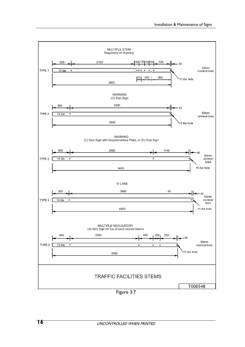
Figure 3.7 Traffic facilities stems .......................................................................................... 16
Figure 5.1 Public utility mains – allocation of space in footways (1) ............................ 22
Figure 5.2 Public utility mains – allocation of space in footways (2) ........................... 23
Figure 5.3 Public utility mains – allocation of space in footways (3) ........................... 24
Figure 5.4 Disposition of sign panels .................................................................................. 25
Figure 7.1 Signposting audit report ..................................................................................... 32
Figure 7.2 Level 1 Structural Inspection Check Sheet ..................................................... 33
Figure 7.3 Level 2 check list for major structures (1) ..................................................... 34
Figure 7.3 Level 2 check list for major structures (2) ..................................................... 35
Figure 7.4 Flowchart for Updating TAIMS ......................................................................... 36
Figure 7.5 TAIMS Update Form ........................................................................................... 37
Tables
Table 7.1 Signposting audit checklist ................................................................................... 31

UNCONTROLLED WHEN PRINTED
Installation & Maintenance of Signs
Amendment record
Please note that the following updates have been made to this document.
Amendment No
Page Description Issued Approved By
1 17 Height of sign shown in dot points amended to 2.5m
April 2011 R O’Keefe Mgr Traffic Policies, Guidelines & Legislation
2 3
19
Various
S2.3 TD Reference updated to TTD 2013/08
Orientation of signs, Figure 5.0 (Reference AS1742.2)
Reference Hyperlinks updated
November 2013
R O’Keefe
Mgr Traffic Policies, Guidelines & Legislation
3 4
6
9-12
Various
20
Steel tube post sizes deemed frangible referenced
Proprietary frangible post products referenced
Steel tube post sizes deemed frangible shown in shaded area on post selection charts. Notes associated with frangible post sizes added.
References to proprietary frangible post products
Clear zone design reference updated
March 2014
R O’Keefe
Mgr Traffic Policies, Guidelines & Legislation
vi
UNCONTROLLED WHEN PRINTED
Installation & Maintenance of Signs
1 Introduction
1.1 Scope
These guidelines set out procedures for the installation and maintenance of signs and their supporting structures.
1.2 Responsibilities and authorisation
The responsibility for installation of road signs is vested with the roads authority which controls the road - either the Roads and Traffic Authority NSW (RTA) or the local Council.
The RTA is responsible for classified roads and Local Government (Council) is responsible for unclassified roads.
All changes to road signs requires appropriate authorisation by the responsible authority.
1.3 Inspection of signs
The appropriate roads authority must regularly inspect and keep an inventory of the signs on its roads. Inspections should review the suitability of each sign, the condition of the sign and its supporting structure as well as reviewing the need for additional signs.
Inspections should also consider the need to retain the sign and its position in relation to the clear zone. If a sign is within the clear zone and it is not frangible, determine if the sign should be removed, relocated, made frangible or protected.
1.4 Procedure for new sign placement
The steps involved in placing a new sign are:-
1. When the need for a new sign is perceived, determine the type of sign, its legend and position, especially with respect to the clear zone.
2. Prepare environmental assessment if required and undertake any consultation necessary.
3. Obtain approval for the sign design in accordance with current RTA policy.
4. Examine the site to ensure that the sign can be placed in the specified location especially with respect to the location of services.
5. AUTHORISE THE INSTALLATION OF THE SIGN
6. Determine the type of support structure required. This will depend on the size of the sign face, its height and, if cantilevered, the distance from the centre of the post to the centre of the sign. Refer Section 5
7. Determine the size of footing required. Refer Section 3
1

UNCONTROLLED WHEN PRINTED
Installation & Maintenance of Signs
8. Order the design of the sign face and support structure.
9. Order the manufacture of the sign face and support structure.
10. Prepare the site for installation.
11. Assemble the structure and install the sign face.
12. RECORD DETAILS OF SIGN INSTALLATION (DATE/TIME ETC)
13. Inspect, maintain and repair the sign as necessary.
Signs should be tracked as part of the asset life cycle management, by documenting as in Section 7.2 Sign Selection
2 Sign Selection
2.1 General
The RTA maintains an electronic register of all standard signs. Access to the RTA Traffic Signs Register is available via:-
www.rms.nsw.gov.au/cgi-bin/index.cgi?action=searchtrafficsigns.form
2.1.1 Regulatory, warning and temporary/road works signs
Most regulatory (including parking), warning and temporary signs are of a standard design as required by AS 1742 and detailed in AS 1743. Signs are generally available in several standard sizes. Refer to the RTA Traffic Signs Register for sizes, details and illustrations of these signs.
2.1.2 Guide signs
Most guide signs have a generally standard layout but require individual design to suit the particular circumstances of the site. Refer to the RTA document, Guide Signposting, for further information or contact the RTA’s Manager, Traffic Policies, Guidelines & Legislation, Traffic Management Branch.
2.2 Panel material
2.2.1 Temporary/road works signs
Temporary signs for road works have traditionally been fabricated using bond wood (plywood) as the sign substrate. However, suitable good quality material is becoming difficult to source. Most road works signs are now fabricated from Colorbond ™ steel (boxed edge) or from the same aluminium used for permanent signs. Refer to RTA Specification QA 3400 Section 2.1 for further details.
2

UNCONTROLLED WHEN PRINTED
Installation & Maintenance of Signs
2.2.2 Permanent signs
Permanent sign blanks are manufactured from an aluminium alloy (type 5251 or 5052 & temper H38) with a thickness of 1.6mm.
Aluminium sign panels wider than 750mm are reinforced to limit deflection about the vertical axis with aluminium channels (extrusion) attached to the sign during manufacture. The vertical spacing of channels is detailed in the RTA’s Specification QA 3400.
2.3 Sign face material
Sign Face materials must be in accordance with: RTA Specification QA 3400, Manufacture and Delivery of Road Signs; and TTD 2013/08, - Approved Retro-reflective Sheeting Materials for Road Signs (www.rms.nsw.gov.au/trafficinformation/downloads/td13-08.pdf)
2.4 Non Standard signs
For signs not listed in the RTA's Traffic Signs Register or listed as No Longer Used, Not Used in NSW or Superseded, the advice of the RTA’s Manager Traffic Policies, Guidelines & Legislation, Traffic Management Branch must be sought if an alternative is not shown.
2.5 Other signs
Other signs which are outside the scope of this document include, but are not limited to Variable Message Signs (VMS) both fixed and mobile, Variable Speed Limit Signs (VSLS), changeable message signs (such as prism signs) and illuminated tunnel and bridge signs.
3 Sign Supports and Footings
3.1 General
The four basic types of sign supports are:
1. galvanised steel tube (the great majority)
2. approved proprietary frangible post products
3. modular structures
4. special structures (individually designed)
Arrangements for placing a sign panel or panels on the structure are detailed in Section 5, and shown in Figure 5.4
All modular and special structures shall comprise materials and weld details complying with the current RTA Drawing No CW8536.
The type of footing required depends on the structure required to support the sign panel. Large panel areas high above the ground, cantilevered over the roadway and in high wind areas require larger footings which have to be
3

UNCONTROLLED WHEN PRINTED
Installation & Maintenance of Signs
purpose designed. For medium sized signs on modular sign structures a standardised footing design can be used. Medium sized signs can be accommodated on approved proprietary frangible post structures with associated standardised footing designs. Small signs mounted on tube posts require a footing that matches the pipe size. Whatever the sign, it is the footing that keeps the sign in place and care must be taken to ensure that the footing is adequate for the proposed sign.
In locations where signs are frequently hit, consideration should be given to relocation, installation on frangible posts or shielding. Where this is not possible, e.g. high median or edge barriers, gores, roundabouts, consider the use of an alternative footing, i.e., sleeved type.
3.2 Wind loading
The type and size of a structure to support sign(s) is dependent on the size and positioning of the sign. The highest loading on a sign is usually wind loading. Australian Standard AS 1170.2 gives details.
When a special sign structure is required, seek advice from the RTA’s Traffic Bridge Engineering Section.
3.2.1 Sign support basics
The RTA’s standard sign arrangement requires the sign panels to be supported so that:
(a) maximum outreach from vertical support to the edge of the sign is 760 mm. Dual posts are positioned at b/5, ie 20% of width from the edge. Triple posts are positioned at b/6 or down to 15% of width from the edge. Some offset is permitted, but keep the load on each post within the post selection chart limit.
(b) maximum span between vertical supports is 2280 mm.
(c) each of the horizontal reinforcing channels on the rear of the panel is fastened to the supporting structure.
(d) where the outreach or span exceeds the limits, an additional vertical support shall be provided to bring the vertical spacing within limits.
3.3 Galvanised steel tube posts
The majority of road signs are erected on galvanised steel tube posts. Material is usually C250 LO and lighter weight C350 LO can be used. They are intended to deform on impact thereby minimising vehicle damage and occupant injuries.
The steel CHS post sizing charts Figures 3.1, 3.2 and 3.3 show the post size (C250 grade steel) appropriate to the sign panel size and its mounting height. These figures also show the post sizes which are deemed to be frangible and are shown in the shaded area of the chart. Refer notes on the post sizing charts for C350 grade steel posts and post spacing which allow sign structure to be deemed frangible.
The post sizes shown as frangible are based on the European Standard EN 12767 - Passive Safety of Support Structures for Road Equipment.
4

UNCONTROLLED WHEN PRINTED
Installation & Maintenance of Signs
Example: A sign with an area of 3.5 square metres and a height to the centre of pressure of 1.8 metres could be supported by either:
1. a single 101.6 x 4.0 CHS post
2. two 76.1 x 3.6 CHS posts
3. three 60.3 x 3.6 CHS posts
Galvanised pipes are used for longevity. The tubes shall be capped to minimise ingress of water and other matter which would prematurely corrode the post.
3.3.1 Deflection
The sign face deflection has generally been kept to less than 3 degrees for steel structure and 1 to 2 degrees for footing movement in the soil, calculated at the annual serviceability (Vs) wind speed. If less deflection is required, reduce the sign area or height of post, or go up to the next size tube.
Sign face stiffness is defined to maintain flatness to the limit of – less than 1 in 40 sign face deflection relative to the maximum post spacing.
3.3.2 Footings
Small and medium signs have the support post planted directly in a concrete footing. The footings sizes are designed to match the strength of the tubes and the ground conditions.
The footings are designed so that movement within the soil will not be excessive, i.e. not more than 12 mm or 2 degrees of twist.
A range of options are given, to provide a match with post size and match footings to site location.
The footing diagram is shown in Figure 3.4. The footing diameter is shown for each post size.
The depths for each post size are also shown in Figure 3.4, giving either the:-
• no path depth, for rural or urban applications without a footpath, i.e. the top 150mm of soil does not provide reliable support or resistance, particularly when the soil is wet.
• footpath application depth, where the footing applicable is also substantially supported by a footpath of minimum 60mm concrete or 80mm bitumen, which also keeps the soil from getting too wet.
• The hole must be made with the surrounding soil undisturbed. It may be auger drilled, once the underground services have been located and ascertained that the operation will not damage or interfere with these services. Where the location of services is uncertain, an exploratory dig by hand is required.
The footing depths are given for soils of two strengths:
• normal, i.e. medium strength as defined by undisturbed loam, firm dry clay, fine dry sand or sandy clay etc
• softer soils, as defined by reactive clay, wet or loose sand, disturbed soil, back fill or made ground. Alternatively increase the depth by the amount of backfill (whichever is the lesser).
5

UNCONTROLLED WHEN PRINTED
Installation & Maintenance of Signs
A single support tube is to have one 14mm diameter hole in which a pin is inserted to prevent rotation of the sign pipe. The post planting depth is 600mm, so the pin is 150mm below the surface. The pin is to be at least 60mm longer than the outside diameter of the tube.
In the small tube cases, the post goes a little deeper than the concrete.
The post is located centrally in the prepared hole. Small tubes are tapped down into the soil to fix vertically and hold it at the specified planting depth. While holding the post vertically, pour the concrete to fill the hole to ground level, trowel smooth and slope to shed water away from the post.
It is preferable for the footing concrete to be allowed to set before the sign is fastened to the post.
3.4 Proprietary frangible post structures
Proprietary frangible post structures (which are approved for use by RMS) are used where the sign is medium sized and design limitations are satisfied (such as for a non-median location and for an infrequent pedestrian activity area). Refer to the RMS website for Frangible Post Product – acceptance documents and design reports for requirements.
3.5 Modular structures
Modular structures are used where the sign is large, proprietary frangible posts are not appropriate and light wall steel tube would not suffice. They may be used for part cantilevered signs. They should be located outside the clear zone or shielded. See Section 5.5, Clear Zone.
Modular structures are post structures consisting of standard galvanised steel components. Posts, arm/s and verticals are selected according to the size of the sign panel and ground clearance requirements.
Refer also to Section 4, Modular Sign Structures.
3.6 Multiple signs
To avoid a proliferation of posts, consideration should be given to erecting two or more signs on the one structure. The total information displayed on the signs must be limited to what can be read, understood and acted upon safely. Refer to AS 1742.2.
Do not erect warning and regulatory signs on the same structure.
6

UNCONTROLLED WHEN PRINTED
Installation & Maintenance of Signs
3.7 Fittings and sign mounting
Steel Tube Structures
Figures 3.1, 3.2 and 3.3 provide charts for use in determining the size of section required for small to medium signs mounted on either one, two or three posts. Details for footings are provided in Figure 3.4.
Brackets and fittings are available for attaching single or multiple sign panels to sign support pipes.
For a single sign the number of bracket assemblies required shall be equal to the product of the number of reinforcing channels (extrusion) and the number of vertical supports.
Pre–drilled support pipe may be sourced from suppliers, and Figures 3.5 and 3.6 show details for various signs.
Proprietary frangible post structures
Refer to the manufacturer’s design manual/installation manual and to the RMS website for Frangible Post Product – Design Report, for fitting details.
Modular Structures
Refer to Section 4, Modular Sign Structures, for fitting details.
Special Structures
These structures are individually designed, and associated fittings would be shown in the individual design drawings.
3.8 Sign panel reinforcing channel – extrusion centre guide
The RTA’s requirements for extrusions are shown in Annexure 3400/G of RTA Specification QA 3400, Manufacture and Delivery of Road Signs.
3.9 Manufacture and delivery
RTA’s requirements for the manufacture, packaging and delivery by the manufacturer of signs panels are detailed in RTA Specification QA 3400, Manufacture and Delivery of Road Signs.
For sign support structures see the relevant RTA Specification.
3.10 Signs on bridges
If signs are required to be attached to bridge structures it is desirable that the need for the signs is known at the time that the bridge is being designed.
If the need arises to attach a sign to an existing bridge structure after the structure is built, or if an existing sign attached to a bridge requires modification, then the matter is to be referred to the RTA’s Engineering Technology Branch for structural determination.
7

UNCONTROLLED WHEN PRINTED
4 Modular Sign Structures
Installation & Maintenance of Signs
Modular structures are used where the sign is large, proprietary frangible posts are not appropriate and light wall steel tube would not suffice. They should only be used outside the clear zone, unless located behind a safety barrier. See Section 5.5, Clear zone.
Modular sign structures are specifically designed by RTA.
Design detail is shown in the current RTA Drawings CW 9746, and covering the required components:
(1) concrete foundation
(2) holding down bolt assembly
(3) post
(4) arm
(5) clamp assembly
(6) verticals
(7) ‘U’ bolt assembly.
There are limitations on the size of the sign panel(s), the ground clearance and offset of these sign panel(s) from the post. This shall be verified by RTA’s Bridge Design Section or a practising structural engineer for structural adequacy.
8

UNCONTROLLED WHEN PRINTED
Installation & Maintenance of Signs
Figure 3.1 – Single Post Selection Chart – Refer Notes 1A & 1B on page 12 for C350 steel posts and frangible post sizes
9

UNCONTROLLED WHEN PRINTED
Installation & Maintenance of Signs
Figure 3.2 – Two Post Selection Chart – Refer Notes 1A, 1B, 2 & 3 on page 12 for C350 steel posts, frangible posts sizes and frangible post spacing
10

UNCONTROLLED WHEN PRINTED
Installation & Maintenance of Signs
Figure 3.3 – Three Post Selection Chart – Refer Notes 1A, 1B, 4 & 5 on page 12
for C350 steel posts, frangible posts sizes and frangible post spacing
11

UNCONTROLLED WHEN PRINTED
Installation & Maintenance of Signs
Notes for Figures 3.1, 3.2 and 3.3 (Steel tube sign post selection charts) are as follows:
Note 1A – Post sizes shown on the charts are for C250 LO grade galvanised steel Circular Hollow Sections (outside diameter shown). Refer table below for alternative specification of post diameter ie nominal bore size for C250 LO grade steel. Refer table below also for alternative post size in C350 LO grade steel.
Note 1B – Post sizes which are deemed to be frangible are shown in the shaded area of the charts.
Note 2 – 76.1x3.6mm C250 (or 76.1x3.2mm C350) post is the maximum size deemed frangible where the post centres are less than 1.5m, except as permitted by Note 3.
Note 3 – 88.9x4.0mm C250 (or 88.9x3.2mm C350) post is the maximum size deemed frangible where:
- the post centres are greater than 1.5 m, or
- the signposted speed zone is 70km/hr or less, the post centres can be less than 1.5m.
Note 4 – 76.1x3.6mm C250 (or 76.1x3.2mm C350) post is the maximum size deemed frangible where the post centres are less than 1.5m, except as permitted by Note 5.
Note 5 – 88.9x4.0mm C250 (or 88.9x3.2mm C350) post is the maximum size deemed frangible where:
- the post centres are greater than 1.5 m, or
- the signposted speed zone is 70km/hr or less, and post centres are greater than 1.2m.
STEEL TUBE SIGN POST TABLE –
CORRESPONDING/EQUIVALENT POST SIZES
C250 LO grade CHS post C250 LO grade CHS post Corresponding standard specification size nominal bore size C350 LO grade CHS post
(outside diameter) (inside diameter) standard specification size (outside diameter)
114.3 x 4.5 CHS 100 NB Medium [4.5mm] 114.3 x 3.2 CHS
101.6 x 4.0 CHS 90 NB Medium [4.0mm] 101.6 x 3.2 CHS
88.9 x 4.0 CHS 80 NB Medium [4.0mm] 88.9 x 3.2 CHS
76.1 X 3.6 CHS 65 NB Medium [3.6mm] 76.1 X 3.2 CHS
60.3 X 3.6 CHS 50 NB Medium [3.6mm] 60.3 X 2.9 CHS
12

UNCONTROLLED WHEN PRINTED
Installation & Maintenance of Signs
Figure 3.4
13

UNCONTROLLED WHEN PRINTED
Installation & Maintenance of Signs
Figure 3.5
14

UNCONTROLLED WHEN PRINTED
Installation & Maintenance of Signs
Figure 3.6
15
UNCONTROLLED WHEN PRINTED
Installation & Maintenance of Signs
Figure 3.7
16

UNCONTROLLED WHEN PRINTED
Installation & Maintenance of Signs
5 Locating Signs
5.1 General considerations
Signs are normally located on the left side of the road in clear view of approaching drivers. Where there are visibility problems e.g. it is a divided carriageway, signs may also be located on the right side. Other circumstances, such as alignment difficulties, may also require signs to be placed on the right side of a road or mounted over the road. This may occur when road–side features, shop awnings and the like would obstruct the visibility of a left side mounted sign, or where advertising matter or visual clutter would negate the effectiveness of the sign. Note that some RTA policies will require signs to be placed on both sides of the road (e.g. at changes in speed zones).
Signs shall not obscure one another nor obscure visibility, particularly at intersections. Signs should not be erected behind trees and power poles and where possible should be placed in sunlight, not shade. For example a good location for signs is at the transition from a fill to a cutting. In urban areas, signs are best located opposite the boundary fence of adjoining properties. Signs in medians or on traffic islands should not obstruct visibility.
Signs should be erected as close to the roadway as practicable, but should be located consistent with the lateral and vertical location clearances and considering the frangibility of the posts.
Refer to Section 5.4 for lateral clearances and height of signs.
Locations with the potential for or record of higher than normal numbers of crashes such as medians, traffic islands and exit ramp gores should be avoided, although if a safety barrier is already provided a sign may be erected behind it, provided it will not compromise the performance and integrity of the safety barrier. However, a safety barrier should not generally be provided solely to protect sign supports. If a safety barrier is not otherwise warranted consider relocating the sign. When a lack of a suitable alternative location necessitates erection of a sign in a crash prone location (and a frangible post is permissible at the location) the sign desirably should be kept to a size that can be erected on a frangible support or structure. As a last resort consider the use of a safety barrier.
17

UNCONTROLLED WHEN PRINTED
Installation & Maintenance of Signs
Large signs in medians should be avoided wherever possible. A risk analysis must be first carried out if this is unavoidable and appropriate treatments adopted. This was undertaken for the structure shown in the photograph above.
5.2 Utilities in footways
Footways are often used to house the mains, cables, pipes, posts etc of various public utility authorities. These authorities have generally agreed to an allocation of space in footways. However, extreme caution shall be undertaken during any excavation. Beginning with the Sydney Streets Opening Conference the space allocation depended on whether the footpath was within the Council of the City of Sydney (CBD). The allocation of space was first revised in 1949, again in 1991 and in 1995 the Conference was reconstituted to be able to cover the whole State and changed its name to the NSW Streets Opening Conference and its most recent document is the Guide to Codes & Practices for Streets Opening, 2009 (refer www.streetsopening.com.au).
Figures 5.1, 5.2 and 5.3 detail the allocation of space in footways.
Where depth is limited by underground services, a pad type footing may be used, as per Figure 3.4.
Dial Before You Dig provides a one-stop service to those needing to determine the presence of underground services in the area of proposed works. As this is not an “instantaneous” service sufficient lead time shall be given to enable any searches to be made. Contact details are:-
www.1100.com.au
Telephone: 1100
18

UNCONTROLLED WHEN PRINTED
Installation & Maintenance of Signs
5.3 Sign placement
5.3.1 Lateral clearance and height
The lateral clearance is essential to avoid signs being hit by tall vehicles that lean over the kerb because of the road crossfall and overhanging loads. Clearance from the kerb to the structure is increased, to allow for the rear overhang of vehicles and truck mirrors when parking. The clearance in unkerbed and faster zones is proportional to travel speed, to enable errant vehicles to regain control. The dimensions given apply to signs of a permanent nature and located on frangible supports and signs for road works and special purposes where these are mounted on posts. The placement and mounting height should be adjusted to achieve the maximum sight distance to the sign, to ensure the sign is clearly visible under headlight illumination at night and to ensure that signs are not obscured by roadside vegetation.
Care shall also be taken to ensure that signs erected under power lines will not be touched by the power lines when they expand and sag in hot weather.
• Rural – On unkerbed roads the lateral clearance of the sign face shall be at least 600mm from the outer edge of road shoulder, line of guide posts or face of safety barrier. The clearance should not be less than 2m nor more than 5m from the edge of the travelled way, except for large guide signs on motorways where greater clearances may be required.
The height of a rural sign should not normally be less than 1.5m above the nearest edge of the travelled way or 2.5m where there are expected to be pedestrians and/or cyclists.
• Urban – On kerbed roads in urban areas the lateral clearance of the sign shall be at least 600mm back from the face of the kerb.
The height of an urban sign which overhangs a footpath shall not be less than 2.5m above the top of kerb to cater for pedestrians and cyclists, Where neither pedestrian nor parked vehicles have to be considered i.e. on traffic islands and medians a height of 1.5m might be more appropriate.
19

UNCONTROLLED WHEN PRINTED
Installation & Maintenance of Signs
Where the sign support is non-frangible the support is to be located outside the clear zone, at the rear of the footway or be protected by a barrier (See Section 5.5.).
5.3.2 Longitudinal placement
The “minimum legibility distance” and the “longitudinal location of a sign” are relative to the approach speed, the time required to read the sign and respond, letter height and the feature to which the sign refers.
“Minimum legibility distance” is dealt with in:
• AS1742.2
• AS1742.6
Longitudinal location of a sign is dealt with in Austroads Guide to Traffic Management, Part 10Traffic Control and Communication Devices Section 4. See also the RTA document Guide Signposting, for a table showing minimum letter heights for both rural and urban situations.
Signs must not be located where glare from the sun makes them difficult or impossible to read. For temporary signs this can mean the need to change the set-up during the day.
5.4 Clear zone
The clear zone is the horizontal width of space available for the safe use of an errant vehicle which consists of the verge area and is measured from the nearest edge of the relevant traffic lane.
Note that the clear zone width increases with speed, plus allowances for embankment or cutting slope and traffic volume. Refer to the RTA’s Supplement to Austroads Guide to Road Design – Part 6, Figure 6.1, Clear Zone Nomograph.
The clear zone should be kept clear of all large, solid (i.e. non frangible) sign supports. If it is not feasible to locate large sign supports outside of the clear zone safety barriers should be provided.
5.5 Signs in medians and islands
A minimum clearance of 300mm should exist between the outer edge of a median or island and the edge of the sign face.
5.6 Orientation of signs
Signs should be mounted relative to the direction of travel of the approaching driver they are intended to serve. On curved alignments, the angle of placement should be determined by the line of sight of approaching traffic rather than the orientation of the road at the point where the sign is located.
To eliminate excessive glare (specular reflection) from the surface of a sign, the sign should be turned about 5° away from the normal to the headlight beam/ line of sight (Figure 5.0). The vertical axis of overhead signs should be tilted back 5° to the line of sight on level and downhill grades. On uphill grades tilt back at 5° to the line of sight, but ensure than no reflection problems occur over the range of approach distances. These help optimise the retro-reflective
20

UNCONTROLLED WHEN PRINTED
Installation & Maintenance of Signs
value at the legibility distance and reduce excessive brightness up close, so the driver perceives the brightness as constant rather than increasing.
It is important to eliminate reflection from the back of the sign, see QA 3400, Manufacture and Delivery of Road Signs, Clause 4.1.1.
Figure 5.0
21

UNCONTROLLED WHEN PRINTED
Installation & Maintenance of Signs
Figure 5.1
22

UNCONTROLLED WHEN PRINTED
Installation & Maintenance of Signs
Figure 5.2
23

UNCONTROLLED WHEN PRINTED
Installation & Maintenance of Signs
Figure 5.3
24

UNCONTROLLED WHEN PRINTED
Installation & Maintenance of Signs
Figure 5.4
25

UNCONTROLLED WHEN PRINTED
6 Installation of Signs
Installation & Maintenance of Signs
6.1 Storage of signs
The packaging, handling and storage of sign panels are critical activities, if the signs are to be installed without damage. Sign panels must be stored vertically in such a way that they will not warp and be protected from damage by other means. It is best to store sign panels in racks especially provided for this purpose. If special racks are not available, the sign panels should be stored vertically supported by wooden uprights.
Care needs to be taken to ensure that sign edges and legend do not become damaged (e.g. abrasion damage caused by dragging on rough surfaces), as this will accelerate deterioration of the sign after erection.
The banding around any signs must be removed during storage and signs stored in outdoor areas or in small non-ventilated indoor areas must be removed from their transport packaging (i.e. cardboard, bubble wrap etc.).
The following photo shows an example of poor storage practice.
6.2 Transporting of sign panels and structures
To avoid damage during transport to erection sites, signs panels should be carried in purpose built racks.
Small signs should be individually wrapped in bubble wrap or cardboard.
It is common with small signs to transport them with posts, fittings and tools in the same vehicle. In these circumstances care should be taken to keep the tools and fittings separate from the signs and tube posts in order to prevent sign damage.
Particular care is needed with larger signs owing to their high cost and the difficulty of on site repair. Larger signs are best transported upright, suitably braced and protected by wooden slats.
26

UNCONTROLLED WHEN PRINTED
Installation & Maintenance of Signs
Take care in off–loading signs and posts on site. They must not be roughly tipped off the vehicle or thrown over the side. Care should also be exercised during erection.
6.2.1 Modular and special structures
For major structures built in accordance with the Authority’s specifications the drawing number is to be welded on all components for ease of identification.
For modular structures, the drawing number is to be welded on all special components. Standard components are to have their type number welded on them.
Care should be taken when handling steel posts to avoid damage to their protective coating. Damage makes a post unsightly and accelerates its corrosion, diminishing its ability to cope with the stresses imposed on it. The greatest stress on a post is where it enters its foundation or the weld to the mounting flange and these are where damage is of greatest concern.
It is not unknown for a sign to be erected differently to the design. For example a large sign with two arms may have the arms interchanged. It is best that, prior to the erection of large structures, the supervisor obtain a general arrangement drawing of the sign so as to minimise the risk of this happening.
6.3 Mounting of sign panels
Signs are normally mounted symmetrically on sign posts. In some cases they may be offset a little to obtain the necessary lateral clearance of the sign or structure. Posts should not protrude above the top edge of the sign panel.
Typical mounting arrangements are shown in Figure 5.4.
6.3.1 Offset signs
For a single sign panel offset from the centre line of the post, it is preferable that the sign panel hide the connection between the cantilever mast arm and the post wherever possible. Arrangements with sign panels overlapping the post are shown in Figure 5.4.
This is more difficult for signs mounted over the road, however these signs generally have a large gap between the panel and the post which visually separates the post from the sign.
6.4 Recording of sign installation approvals
The appropriate roads authority must maintain records of all sign installation approvals.
6.5 Recording of sign installation details
The appropriate roads authority must maintain records of all sign installations. These records should include installation time and date.
27

UNCONTROLLED WHEN PRINTED
7 Sign Life Cycle Management
Installation & Maintenance of Signs
7.1 General
Signs, like many assets, have a limited life cycle. This life cycle should be tracked by using an updateable computer database, such as TAIMS, and consists of:
• design
• approval
• order number
• approval document and date
• design, with legend and symbol details
• sign number (if applicable)
• foreground/background material
• structure & footing
• sign type (W = warning etc.)
• sign size, A, B, C if appropriate, width x height for large direction signs
• manufacture of sign face and structure
• Installation date
• audit condition, appropriateness & when replacement due
• maintenance, to ensure the asset is performing satisfactorily
• repair, due to damage
• replacement of the sign face, due to age or the need to change the message
• replacement or removal of the sign structure.
It is important that this life cycle is understood and taken it into account when planning, estimating and budgeting.
A quality management system should document the processes involved at each of these stages. These processes will vary from organisation to organisation, depending upon the structure of the organisation and the delegation of authority and responsibility within the organisation.
Signs are assets and like any other asset, need an asset register to keep the organisation informed of their condition and time for replacement. They need regular maintenance and repair if the sign life is to be maximised. Large sign faces, such as graphical advance direction signs can cost many thousands of dollars to manufacture, plus thousands more to remove the old sign face and install the new face, and may typically have a life of up to 20 years. If by poor maintenance sign faces have to be replaced earlier, the effect on the budget could be significant.
To minimise the whole–of–life cost of signs, it is necessary to maximise the life of the sign. It is therefore good practice to conduct a regular, documented audit of signs and their supporting structures to ensure that small problems are fixed before they become bigger and expensive.
28

UNCONTROLLED WHEN PRINTED
Installation & Maintenance of Signs
A system shall be established for regional inspectors/supervisors to receive and resolve problems associated with all signs and small to medium sized support structures identified by the general public. For major support structures issues raised by the general public shall be referred to the dedicated Sydney Project Services Traffic Asset Structures’ inspectors.
7.2 Why inspect?
The key to cost control is good maintenance, and the key to good maintenance is regular and systematic inspection.
If inspections are to be effective, problems need to be documented, together with appropriate follow–up action. A suggested form for use in signposting for all signs and small to medium sized support structure inspections is given in Figure 7.1. A similar form is also provided in Figure 7.2 and it should be used in preference to that provided in Figure 1.1 when forwarding structural issues to Sydney Project Services dedicated Traffic Asset Structures personnel. The form to be used for structural integrity and condition assessment of major support structures is provided in Figure 7.3. Use of a GPS data logger will allow information to be recorded while travelling and provide a more detailed assessment.
7.3 Inspection items
Table 7.1 shows a signposting checklist which can be used when inspecting signs and small to medium sign support structures. An alternative form specifically for structures is provided in Figure 7.2. The checklist shown in Figure 7.3 must be used for major structures and inspections shall be performed by dedicated Sydney Project Services Traffic Asset Structures’ inspectors.
Follow up: After each sign inspection, follow–up action must be taken. Appropriate follow–up may be:
• Reposition existing sign
• Remove existing sign
• Carry out minor maintenance, for example sign cleaning, scrub clearing
• Repair existing sign
• Replace damaged or outdated legend
• Remove and replace existing sign face
• Patch replace damaged legend or background (if original is not too old)
• Erect new sign.
Maintenance should not arise purely as a result of inspections by engineers and supervisors. Signs should be regularly checked by maintenance gangs and other staff. Such inspections are classified as level 1 in accordance with the “Processes and Procedures Manual for Structural Integrity Inspection and Condition Assessment of Traffic Asset Structures”. Minor repairs within the capabilities of the gang should be carried out immediately. The need for major repairs or replacement for small to medium sized support structures should be reported to the Regional inspector/supervisor. A Sydney Project Services Traffic Asset Structures’ inspector shall be contacted prior to initiating major repairs to or replacement of major support structures.
29

UNCONTROLLED WHEN PRINTED
7.4 Sign face replacement
Installation & Maintenance of Signs
The date of manufacture is stamped on the back of each sign. With proper care a sign should last up to 20 years. In protected areas they may last this long, but many get damaged well before the normal life span. It is good practice to have a list of all signs on a length of road that includes the age of the sign face and its cost, along with its current condition and expected time for replacement.
When considered with the audit results, a budget for the replacement of sign faces can be made with a reasonable degree of accuracy.
When a sign requires replacement in less than five years, the cause should be investigated. Possible reasons are:
• poor maintenance
• harsh environment (salt spray, industrial fumes, exhaust fumes at toll booth or bridge)
• a site or design which is prone to vandalism.
If the problem is a local one, action should be taken to prolong the life of the sign, e.g. using better materials or repositioning the sign. If the problem is a general one, then it should be brought to the attention of the responsible person. Action should then be taken with the appropriate people (suppliers, designers, etc.) so that appropriate changes can be made.
30

UNCONTROLLED WHEN PRINTED
Installation & Maintenance of Signs
Problem Possible cause Is the sign missing? • vandals
• crash damage • removal for construction or road maintenance and
forgotten Is the sign necessary • conditions have changed
• unauthorised • not really needed in the first place
Is the sign noticeable? • poor location • poor orientation • shadow • competing signs
Is the sign face obscured?
• trees, bushes, grass • other signs • utility posts
How old is the sign material
• record age and material class as marked on sign back
• compare condition to age Is the message legible in daytime?
• dirt • deterioration of the sign face
Does sign back cause reflection
• not angled correctly • reflects morning or late afternoon sunlight • reflects car lights • needs matt paint
Is the message legible at night?
• specular (mirror) reflection. Check 5° from sight– line
Is the sign securely mounted?
• base • holding down bolts • clamps etc.
Is there a need for a new sign?
• conditions have changed • sign previously missed etc.
Other reasons sign needs maintenance or replacement?
Table 7.1 Signposting audit checklist
31

UNCONTROLLED WHEN PRINTED
Installation & Maintenance of Signs
Road/Suburb/shire: From: To:
Office: Inspecting officer:
Odometer commences at: Date: Time:
Odometer reading
Description
Action code α
Notes or required action
Action codes α Sign Status Code Action
Existing
1 Retain as existing 2 Re–orient sign 3 Remove sign (not needed) 4 Clean sign 5 Minor repairs 6 Replace sign 7 Insulate- fix dew or frost problem 8 Unauthorised sign (remove)
Not existing 9 New installation of sign
Figure 7.1 Signposting audit report
32

UNCONTROLLED WHEN PRINTED
Installation & Maintenance of Signs
Figure 7.2 Level 1 structural inspection checklist
33

UNCONTROLLED WHEN PRINTED
Installation & Maintenance of Signs
Figure 7.3 Level 2 check list for major structures
34

UNCONTROLLED WHEN PRINTED
Installation & Maintenance of Signs
Figure 7.3 Level 2 check list for major structures (continued)
35
UNCONTROLLED WHEN PRINTED
Installation & Maintenance of Signs
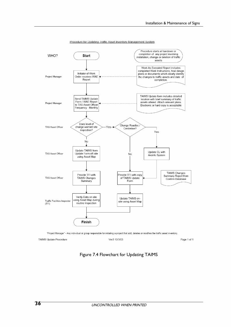
Figure 7.4 Flowchart for Updating TAIMS
36

UNCONTROLLED WHEN PRINTED
Installation & Maintenance of Signs
Figure 7.5 TAIMS Update Form
37

UNCONTROLLED WHEN PRINTED
8 Maintenance
Installation & Maintenance of Signs
8.1 Introduction
Sign maintenance is necessary to ensure that a sign performs according to its design, by conveying the appropriate message to the driver. Proper maintenance will help drivers to read and understand signs. This will reduce driver stress and assist in reducing crashes.
The cost of providing signs varies considerably. The cost of maintenance is cheap compared to the crash risk costs of inadequate signage. Maintenance must be considered in this light.
Signs are easily damaged if roughly treated by being dropped or walked on during installation. Signs may also be deliberately damaged by vandals. Like all equipment signs have an economic maximum life after which they should be replaced. Signs may, like other equipment, age prematurely through neglect of simple maintenance.
Maintenance may be either preventive or remedial. Preventive maintenance is generally cheaper and less disruptive to other work. Remedial maintenance should only be needed after damage, typically by vandalism or by a motor vehicle crash.
The key to good maintenance is regular and systematic inspection, with prompt rectification.
8.2 Maintaining sign supports
Sign supports will require periodic maintenance. Damaged posts shall be repaired or replaced. Those hit more often shall be replaced in a sleeved footing, or to be repositioned where they do not get hit.
8.2.1 Posts, large cantilevers and gantries
Generally steel posts are hot dipped galvanised. If regularly bent by vandals, extra light 50 mm NB posts can be replaced by a heavier grade. If bent, but not buckled, galvanised steel pipe posts up to approximately 80 mm diameter may be straightened in situ. Larger posts may require either replacement or removal and workshop straightening.
Very large or multiple signs are supported on steel structures (typically cantilevers or gantries) which have been specifically designed for the site and purpose. If these suffer other than minor damage they require a level 2 or 3 inspection as defined by the “Processes and Procedures Manual for Structural Integrity Inspection and Condition Assessment of Traffic Asset Structures”. They may need to be dismantled and properly repaired or replaced if there is any possibility of further collapse.
8.2.2 Bolts and brackets
All permanent signs are to be attached to their supports by galvanised or stainless steel bolts and nuts to prevent corrosion and marking the sign with rust stains.
38

UNCONTROLLED WHEN PRINTED
Installation & Maintenance of Signs
Bolts are to be checked periodically for tightness and re–tightened if necessary. It is suggested that this be done in conjunction with the periodic washing of the sign. Rusted mountings must be replaced.
8.3 Maintaining sign panels
To operate satisfactorily sign faces should be kept clean and not allowed to deteriorate beyond an operational retro-reflective level.
8.3.1 Normal washing
Signs should be washed periodically, to remove dust, mud, grime, industrial deposits or salt spray.
A soft brush (definitely not with stiff bristles) or mop is the desirable tool for cleaning a sign. The brush or mop may have a hose connected. Water may be supplied by drums, pump, hoses and nozzles.
The cleaning method is:
• flush with water to remove loose dirt and grit
• wash with soft brush and detergent solution keeping a flow of water to the sign as brushing proceeds
• rinse with clean water.
Retro-reflective signs should be checked for cracking, crazing, peeling or other visual defects
Avoid the use of high-pressure sprayers and do not direct sprays onto sign face edges.
8.3.2 Paint or graffiti damage
The treatment for paint or graffiti damage is:
• scrub the defaced area with a soft cloth soaked in a recommended commercial graffiti remover
• wipe with a clean rag
• give the sign face a normal wash and remove all graffiti remover
• a graffiti resistant protective overlay film supplied by the sign manufacturer may be used in locations subjected to attack.
8.3.3 Other deposits
To treat bitumen, grease, diesel or other exhaust soot, crayon, etc:-:
• gently wipe the defaced area with a soft cloth soaked in a solvent such as isopropyl alcohol (mixed 50% with water)
• wipe the sign face with a dry rag
• give the sign face a normal wash.
39

UNCONTROLLED WHEN PRINTED
8.3.4 Fading and loss of colour
Installation & Maintenance of Signs
Where the material of the sign legend or background has lost a significant amount of colour or has faded significantly, e.g. on screened STOP (R1–1) signs, the sign should be replaced.
40