installation and instructions 2 - aplus waterapluswater.org/eliminator pro manual.pdf ·...
TRANSCRIPT

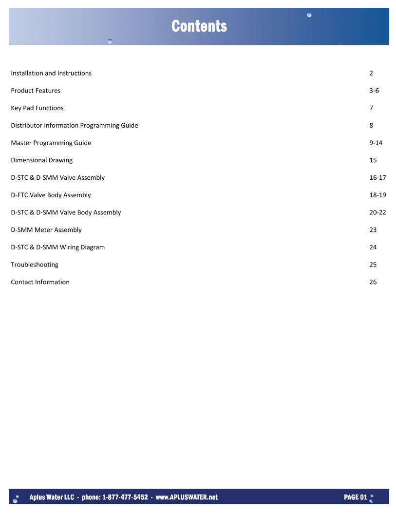
Installation and Instructions 2 Product Features 3-6 Key Pad Functions 7 Distributor Information Programming Guide 8 Master Programming Guide 9-14 Dimensional Drawing 15 D-STC & D-SMM Valve Assembly 16-17 D-FTC Valve Body Assembly 18-19 D-STC & D-SMM Valve Body Assembly 20-22 D-SMM Meter Assembly 23 D-STC & D-SMM Wiring Diagram 24 Troubleshooting 25 Contact Information 26

Water Pressure: A minimum of 20 psi inlet water pressure is required for effective regeneration. Electrical Facilities: An uninterrupted alternating current (AC) supply is required. Please make sure your voltage supply is compatible with your unit before installation. Existing Plumbing: Condition of existing plumbing should be free from lime and iron buildup. Piping that has heavy buildup with lime and/or iron should be replaced. If piping is clogged with iron, a separate iron filter unit should be installed ahead of the water softener. Location of Softener and Drain: The softener should be located close to a clean working drain and connected according to local plumbing codes. Bypass Valves: Always provide for the installation of a bypass valve if unit is not equipped with one.
Water pressure is not to exceed 120 psi, water temperature is not to exceed 110°F, and the unit cannot be subjected to freezing conditions.
Installation Instructions 1. Place the softener tank where you want to install the unit, making sure the tank is level and on a firm base. 2. All plumbing should be done in accordance with local plumbing codes. The pipe size for the drain line should be a minimum of
½”. Backwash flow rates in excess of 7gpm or length in excess of 20’ require ¾” drain line. 3. The 1” distributor tube (1.05 O.D) should be cut flush with top of tank. 4. Pre-lubricate the distributor o-ring seal and tank o-ring seal. Twist the valve on to the tank. If applicable, pre-lubricate the plastic
bypass o-ring seals and inside the plastic yoke before attaching to valve. Silicone lubricant is the only lubrication recommended.
5. Solder joints near the drain must be done prior to connecting the Drain Line Flow Control fitting (DLFC). Leave at least 6” between the DLFC and solder joints when soldering pipes that are connected on the DLFC. Failure to do this could cause interior damage to the DLFC.
6. Teflon tape is the only sealant to be used on the drain fitting. 7. Make sure that the floor is clean beneath the salt storage tank and that it is level. 8. On units with a bypass, place in bypass position. Turn on the main water supply. Open a cold soft water tap nearby and let
run a few minutes or until the system is free from foreign material that may have resulted from the installation. Once clean, close the water tap.
9. Place the bypass in service position and let water flow into mineral tank. When water flow stops, slowly open a cold water tap nearby and let run until the air is purged from the unit.
10. Plug unit into an electrical outlet. Note: All electrical connections must be connected according to local codes.
11. Add 7 inches of water to brine tank to cover air check on float. Manually step the valve to the Brine Draw position and allow the valve to draw water from the brine tank until it stops. Note: The air check will check at approximately the midpoint of the screened intake area.
12. Next, manually step the valve to the Brine Refill position and allow the valve to return to Service automatically. 13. With the valve in Service, check that there is about 1.0” of water above the grid in the brine tank, if used. 14. Fill the brine tank with salt. 15. Set-up is now finished; the control can now be left to run automatically.

In Service Display Timed Regeneration Mode: The display will show the current time, day of the week, and remaining time until the next set regeneration. Meter Immediate Regeneration Mode: The display will show the current time, day of the week, and amount of treated water remaining until next regeneration.
Meter Delay Regeneration Mode: The display will show the current time, day of the week, and amount of remaining treated water. At zero the display changes to the regeneration time set by the user.
Weekly Regeneration Mode: The display will show the current time, day of the week, and the remaining time until the next set regeneration. Current Time-Hours
Current Time-Minutes
AM/PM
Day of the Week
Time Remaining Until Next Regeneration
Valve Stage
Meter Icon-Rotates When Meter is Operational
Remaining Amount of Treated Water Left Prior to Regeneration
Volume Unit
Meter Delay Activated Icon
Day of Week for Next Regeneration

Automatic Keypad Lock
If the keypad is not used for 3 minutes, the keyboard will be locked. To release, press any key to illuminate the screen, then
press the button and then the button.
Memory During Power Failure
All program settings are stored in permanent memory. Current valve position, cycle step elapsed, and time of day are stored during a power failure. Reset of current time is necessary when powering up.
If the valve stopped at a regeneration stage during a power outage. The valve will begin at the prior position before the outage occurred. It takes 4-5 minutes to reset to the position.
Restore Factory Settings
Press and hold the button. The following screen displays.
Release the button. The valve has restored the factory default settings.
Fault Alarm The system will automatically detect errors. If an error is found the following screen displays.
In this state, please cut off the power supply and then re-apply the power. If the errors are removed the valve will either stop in service position or reset. If conditions persist, contact your local supplier for more assistance.
No Hard Water Bypass The D-Series valves are designed with the option of a no hard water bypass piston, which ensures no hard water out of the outlet in the process of regeneration.
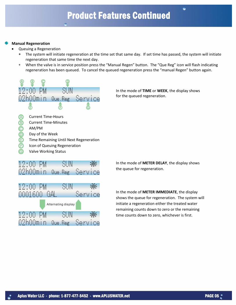
Manual Regeneration
Queuing a Regeneration
The system will initiate regeneration at the time set that same day. If set time has passed, the system will initiate regeneration that same time the next day.
When the valve is in service position press the “Manual Regen” button. The “Que Reg” icon will flash indicating regeneration has been queued. To cancel the queued regeneration press the “manual Regen” button again.
In the mode of TIME or WEEK, the display shows for the queued regeneration.
Current Time-Hours
Current Time-Minutes
AM/PM
Day of the Week
Time Remaining Until Next Regeneration
Icon of Queuing Regeneration
Valve Working Status
In the mode of METER DELAY, the display shows
the queue for regeneration.
In the mode of METER IMMEDIATE, the display
shows the queue for regeneration. The system will
initiate a regeneration either the treated water
remaining counts down to zero or the remaining
time counts down to zero, whichever is first.

Regenerating Immediately
When the valve is in service position press and hold the button for 5 seconds. The valve immediately advances to the stage of regeneration.
Current Time
“GO TO BackWash” Flashes
When time counts down to zero or press again to advance to next stage “GO TO BrineDraw” Flashing
When time counts down to zero or press again to advance to next stage “GO TO RapidRinse” Flashing
When Time counts down to zero or press
again to advance to next stage
“GO TO ReFill” Flashing
When time counts down to zero or press again to advance to next stage
“GO TO Service” Flashing

“Right Arrow” button moves the cursor to parameters for change.
“Up Arrow” button increases the value of the selected parameters or confirm the selected parameters.
“Time & Day” button sets the current time and day.
“Mode” button selects the valve regeneration type. There are 4 mode regeneration options: Timer, Meter Immediate, Meter
Delayed, and Week Day initiated regenerations.
“Set Regen” button sets the appropriate requirements such as the regeneration time and water capacity for the specific mode
selected.
“Set Cycle” button sets the duration of Backwash, Brine Draw, Rapid Rinse, and Brine Refill.
“Manual Regen” button manually initiates an immediate regeneration or a queued regeneration.

Press and hold the “Mode” button while simultaneously powering up the valve. Edit: Editing and input information OFF: Exit
Move & Select
Confirm
Input distributor name and telephone number or email address. Total 2 lines Move the cursor right to desired position.
Move cursor left to desired position.
Delete character and move to next position.
Move the cursor right to desired capital letter.
Confirm choice. Move the cursor up or down a line.
Move the cursor right to desired lower case letter. Confirm choice.
Move the cursor up or down a line.
Save and exit setup. If no key is pressed, the screen will time out after 10 minutes. Changes will not be saved and display will return to service screen.
Once saved this information will display alternating with the “In Service” information.
Press and hold the button for 5 seconds to display the distributor information for 10 seconds.

Time & Day (Example: 2:30AM WED)
Default Setting
Increase hour number to “02”. AM and PM change automatically according to the hours changing.
Move cursor to minute number.
Increase minute number to “30”.
Move cursor to desired day of week.
Confirm. Cursor will automatically move to next position.
Save and Exit. If this button is not pressed within 5 minutes, changes will not be saved and the display will return to service screen.
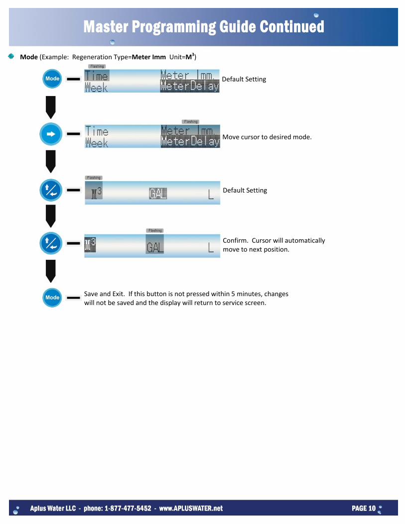
Mode (Example: Regeneration Type=Meter Imm Unit=M3)
Default Setting
Move cursor to desired mode.
Default Setting
Confirm. Cursor will automatically move to next position.
Save and Exit. If this button is not pressed within 5 minutes, changes will not be saved and the display will return to service screen.

Set Regen-Time Mode (Example: Time=02:30 AM Day Override=05)
Default Setting
Move cursor to minute number.
Increase minute number to “30”.
Move cursor to desired day override number.
Increase day override number to “5”.
Save and Exit. If this button is not pressed within 5 minutes, changes will not be saved and the display will return to service screen.

Set Regen-Meter Imm Mode (Example: Capacity=0002000 GAL) Default Setting
Move cursor to desired capacity number.
Increase capacity number to “2”.
Move cursor to next desired capacity number.
Increase capacity number to “0”.
Save and Exit. If this button is not pressed within 5 minutes, changes will not be saved and the display will return to service screen.
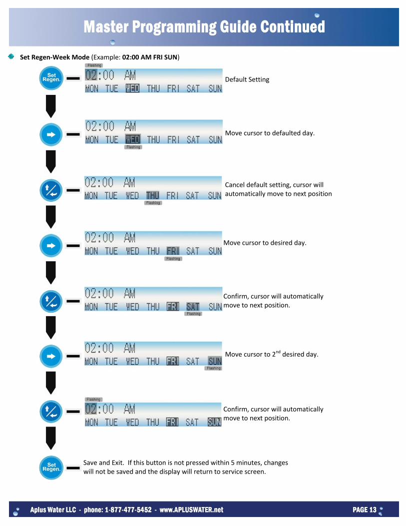
Set Regen-Week Mode (Example: 02:00 AM FRI SUN)
Default Setting
Move cursor to defaulted day.
Cancel default setting, cursor will automatically move to next position
Move cursor to desired day.
Confirm, cursor will automatically move to next position.
Move cursor to 2nd desired day.
Confirm, cursor will automatically move to next position.
Save and Exit. If this button is not pressed within 5 minutes, changes will not be saved and the display will return to service screen.

Set Regen-Meter Delay Mode Default Setting
Use mode of “Time” and “Meter Imm” to set.
Save and Exit. If this button is not pressed within 5 minutes, changes will not be saved and the display will return to service screen.
Set Cycle
Default Setting “BackWash” and “RapidRs” cannot be set to “000”.
Move cursor to desired number.
Increase to desired number.
Save and Exit. If this button is not pressed within 5 minutes, changes will not be saved and the display will return to service screen.


Item No. Quantity Part No. Description
1 1 50090 Keypad Label
2 1 50014 Front Cover
3 1 07031 Circuit Board; Timer
4 6 02110 Screw
5 12 02106 Screw
6 2 02081 Screw
7 2 06003 Switch; Micro
8 2 06051 Insulator
9 1 C0001 Wire Set
10 1 50015 Main Gear
11 1 50016 Brine Gear
12 1 50023 Top Cover
13 1 50013 Bracket
14 1 50024 Gear Cover
15 1 50018 Main Cam
1 50028 Main Cam; Filter
16 1 04002 Washer
17 1 00105 Pin
18 1 13265 Motor
19 1 07030 Transformer
20 1 07021 DC Socket
21 1 07091 Wiring Fastener
22 1 50017 Brine Cam; NHW
1 50027 Brine Cam

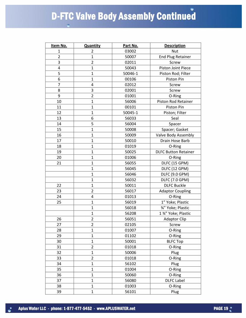
Item No. Quantity Part No. Description
1 2 03002 Nut
2 1 50007 End Plug Retainer
3 2 02011 Screw
4 1 50043 Piston Joint Piece
5 1 50046-1 Piston Rod; Filter
6 1 00106 Piston Pin
7 4 02012 Screw
8 3 02001 Screw
9 2 01001 O-Ring
10 1 56006 Piston Rod Retainer
11 1 00101 Piston Pin
12 1 50045-1 Piston; Filter
13 6 56033 Seal
14 5 56004 Spacer
15 1 50008 Spacer; Gasket
16 1 50009 Valve Body Assembly
17 1 50010 Drain Hose Barb
18 1 01019 O-Ring
19 1 50025 DLFC Button Retainer
20 1 01006 O-Ring
21 1 56055 DLFC (15 GPM)
1 56045 DLFC (12 GPM)
1 56046 DLFC (9.0 GPM)
1 56032 DLFC (7.0 GPM)
22 1 50011 DLFC Buckle
23 2 56017 Adaptor Coupling
24 4 01013 O-Ring
25 1 56019 1” Yoke; Plastic
1 56018 ¾” Yoke; Plastic
1 56208 1 ¾” Yoke; Plastic
26 2 56051 Adaptor Clip
27 2 02105 Screw
28 1 01007 O-Ring
29 1 01102 O-Ring
30 1 50001 BLFC Top
31 2 01018 O-Ring
32 1 50006 Plug
33 2 01018 O-Ring
34 1 56102 Plug
35 1 01004 O-Ring
36 1 50060 O-Ring
37 1 56080 DLFC Label
38 1 01003 O-Ring
39 1 56101 Plug

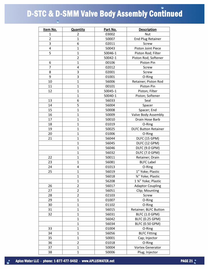
Item No. Quantity Part No. Description
1 2 03002 Nut
2 1 50007 End Plug Retainer
3 6 02011 Screw
4 1 50043 Piston Joint Piece
5 1 50046-1 Piston Rod; Filter
2 50042-1 Piston Rod; Softener
6 1 00106 Piston Pin
7 4 02012 Screw
8 3 02001 Screw
9 3 01001 O-Ring
10 1 56006 Retainer; Piston Rod
11 1 00101 Piston Pin
12 1 50045-1 Piston; Filter
1 50040-1 Piston; Softener
13 6 56033 Seal
14 5 56004 Spacer
15 1 50008 Spacer; End
16 1 50009 Valve Body Assembly
17 1 50010 Drain Hose Barb
18 1 01019 O-Ring
19 1 50025 DLFC Button Retainer
20 1 01006 O-Ring
21 1 56044 DLFC (15 GPM)
1 56045 DLFC (12 GPM)
1 56046 DLFC (9.0 GPM)
1 56032 DLFC (7.0 GPM)
22 1 50011 Retainer; Drain
23 1 56081 BLFC Label
24 4 01013 O-Ring
25 1 56019 1” Yoke; Plastic
1 56018 ¾” Yoke; Plastic
1 56208 1 ¾” Yoke; Plastic
26 2 56017 Adaptor Coupling
27 2 56051 Clip; Mounting
28 2 02103 Screw
29 1 01007 O-Ring
30 1 01102 O-Ring
31 1 56015 Retainer; BLFC Button
32 1 56031 BLFC (1.0 GPM)
1 56042 BLFC (0.25 GPM)
1 56034 BLFC (0.50 GPM)
33 1 01004 O-Ring
34 1 56056 BLFC Fitting
35 1 50001 Cap; Injector
36 2 01018 O-Ring
37 1 50004 Vortex Generator
38 1 50006 Plug; Injector

Item No. Quantity Part No. Description
39 1 50003 Injector Nozzle (#4)
1 50030 Injector Nozzle (#0)
1 50032 Injector Nozzle (#1)
1 50034 Injector Nozzle (#2)
1 50036 Injector Nozzle (#3)
40 2 01017 O-Ring
41 1 50002 Injector Throat (#4)
1 50029 Injector Throat (#0)
1 50031 Injector Throat (#1)
1 50033 Injector Throat (#2)
1 50035 Injector Throat (#3)
42 1 50060 O-Ring
43 1 50005 Screen Injector
44 1 56080 DLFC Label
45 1 01105 O-Ring
46 1 56010 Brine Valve Spacer
47 1 01003 O-Ring
48 1 56007 Brine Valve Cap
49 1 56058 Spring; Brine Valve
50 1 56030 Brine Valve Seat
51 1 56054-1 Brine Valve Stem
52 1 04001 Washer; Brine Valve
53 1 04053 Retaining Ring
54 1 50041-1 Bypass Piston
55 1 01021 O-Ring

Item No. Quantity Part No. Description
1 1 56013 Flow Straightener
2 1 50022-1 Meter Cable Assembly
3 4 01013 O-Ring; Meter Body
4 1 1220E Meter Assembly
5 2 50044 Adaptor Clip
6 2 02105 Screw; Adaptor Clip


Symptom Probable Cause Correction
1. Softener Fails to regenerate automatically.
A. Cord plugged into intermittent or dead power source. B. Disconnected meter cable. C. Defective power cord. D. Defective timer, meter, or sensor.
A. Connect to constant power source B. Reconnect cable. C. Replace cord D. Replace or repair.
2. Regenerating at wrong time. A. Timer improperly set due to power failure.
A. Reset timer.
3. Loss of capacity. A. Increased raw water hardness. B. Brine concentration and/or quality. C. Contaminated resin D. Poor distribution, Channeling (uneven bed surface) E. Interval valve leak. F. Resin age. G. Resin loss
A. Reset unit to the new capacity. B. Keep brine tank full of salt. Clean brine tank yearly. Salt may be bridged. If using a salt grid plate, ensure refill water is in contact. C. Call dealer, find out how to confirm it, clean resin, and prevent future fouling. D. Call dealer. Check distributors and backwash flow. E. Call dealer. Replace spacers, seals, and/or piston. F. Call dealer. Check for resin oxidation caused by chlorine. or mushy resin. G. Call dealer. Check for correct bed path, broken distributors, air or gas in bed, well gas eliminator, or loose brine line.
4. Poor water quality. A. Check items in #3. B. Bypass valve open. C. Channeling.
A. Check items in #3. B. Close bypass valve. C. Check for too slow or high service flow. Check for media fouling.
5. High salt usage. A. High salt setting. B. Excessive water in brine tank.
A. Adjust salt setting. B. See symptom #7.
6. Loss of water pressure. A. Scaling/buildup of inlet pipe. B. Contaminated resin C. Improper backwash.
A. Clean or replace pipeline. Pretreat to prevent. B. Clean the resin. Pretreat to prevent. C. Too many resin fines and or sediment. Call dealer, reset backwash flow rate and/or adjust time.
7. Excessive water in brine tank and/or salty water to service.
A. Plugged drain line. B. Dirty or damaged brine valve. C. Plugged injector. D. Low inlet pressure. E. Timer not cycling.
A. Check flow to drain. Clean flow control. B. Clean or replace brine valve. C. Clean injector and replace screen. D. Increase pressure to allow injector to perform properly (20 psi minimum). E. Replace timer.
8. Softener fails to use salt. A. Plugged/restricted drain line. B. Injector plugged. C. No water in brine tank. D. Water pressure is too low. E. Brine line injects air during brine draw. F. Internal control leak.
A. Clean drain line and/or flow control. B. Clean or replace injector or screen. C. Check for restriction in BLFC. Ensure safety float is not stuck. D. Line pressure must be at least 20 psi. E. Check brine line for air leaks. F. Call dealer. Check piston, seals, and spacers for scratches and dents.
9. Control cycles continuously. A. Faulty timer. A. Replace timer.
10. Continuous flow to drain. A. Foreign material in control. B. Internal control leak. C. Valve jammed in brine or backwash position. D. Timer motor stopped or jammed.
A. Call dealer. Clean valve/rebuild unit. B. Same as above. C. Same as above. D. Replace timer motor.

Thank you again for choosing this control valve for water treatment systems. Please contact your service professional with questions.
Place contact information
here.